

Page 1

GC20618-1E
Heavy Duty Compound Feed Lockstitch
Sewing Machine With Edge Binder
Instruction Manual
Parts Catalog
Page 2

CONTENTS
PRECAUTIONS BEFORE STARTING OPERATION ---------------------------------------------- 1
PREPARATION FOR OPERATION
1. Power cable connection -------------------------------------------------------------------------------------------- 2
2. C
onnection of control box -----------------------------------------------------------------------------------------
CAUTIONS ON USE
1. Oiling (1) -------------------------------------------------------------------------------------------------------------- 3
2. O
iling (2) --------------------------------------------------------------------------------------------------------------
3. O
iling condition -----------------------------------------------------------------------------------------------------djustment of oiling to rotating hook ---------------------------------------------------------------------------
4. A
autions on operation -----------------------------------------------------------------------------------------------
5. C
OPERATION
1. Installation of needles ----------------------------------------------------------------------------------------------- 4
2. W
3. T
4. S
5. T
6. Tension adjustment of bobbin threads --------------------------------------------------------------------------- 6
7. B
8. N
9. A
10. T
11. Adjustment of feed dog height ------------------------------------------------------------------------------------ 7
12. R
13. R
14. R
15. S
16. Upper feed adjustment (needle side) ---------------------------------------------------------------------------- 10
17. O
inding of bobbin thread ------------------------------------------------------------------------------------------
hreading of needle threads ---------------------------------------------------------------------------------------
etting of bobbin ---------------------------------------------------------------------------------------------------hreading of bobbin threads ---------------------------------------------------------------------------------------
alance of thread tension -----------------------------------------------------------------------------------------eedle thread tension ----------------------------------------------------------------------------------------------djustment of presser foot pressure ------------------------------------------------------------------------------
iming between rotating hook motion and needle motion ---------------------------------------------------
elationship between rotating hook motion and take-up lever motion -----------------------------------elationship between hook motion and opener motion -----------------------------------------------------elationship between needle motion and feed dog motion --------------------------------------------------
afety clutch device -------------------------------------------------------------------------------------------------
utside presser foot and inside presser vertical stroke adjustment ----------------------------------------
3
3
4
4
4
5
5
6
6
6
6
7
7
8
8
8
9
10
SPECIFICATIONS ------------------------------------------------------------------------------------------------- 10
Page 3

PRECAUTIONS BEFORE STARTING OPERATION
1. Safety precautions
1) When turning the power on, keep your hands and fingers away from the area around/under the
needle and the area around the pulley
ower must be turned off when the machine is not used, or when the operator leaves his/her seat.
2) P
3) The power must be turned off before tilting the machine head, installing or removing the “V” belt,
djusting the machine, or when replacing.
a
4) Avoid placing fingers, hairs, bars etc. near the pulley, “V” belt, bobbin winder pulley, or motor
when the machine is operation. Injury could result
o not insert fingers into the thread take-up cover, under/round the needle, or pulley when the
5) D
machine is in operati
6) I
f a belt cover, finger guard, and/or eye guard are installed, do not operate the machine without
these safety devices.
on.
.
.
2. Precaution before Starting Operation
f the machine’s oil pan has an oil sump, never operate the machine before filling it.
1) I
2) If the machine is lubricated by a drop oiler, never operate the machine before lubricating.
3) When a new sewing machine is first turned on, verify the rotational direction of the pulley wit
the power on. (the pulley should rotate counterclockwise when viewed from the pulley.)
h
4) Verify the voltage and (single or three) phase with those given on the motor nameplate.
3. Precaution for Operating Conditions
1) Avoid using the machine at abnormally high temperature (35℃ or higher) or low temperature
(5℃or lower). Otherwise, machine failure may result.
2) Avoid using the machine in dusty conditions.
void using the machine in areas where too much electrical noise, resulted from the
3) A
high-frequency welder and others, is gener
ated.
— 1 —
Page 4
PREPARATION FOR OPERATION
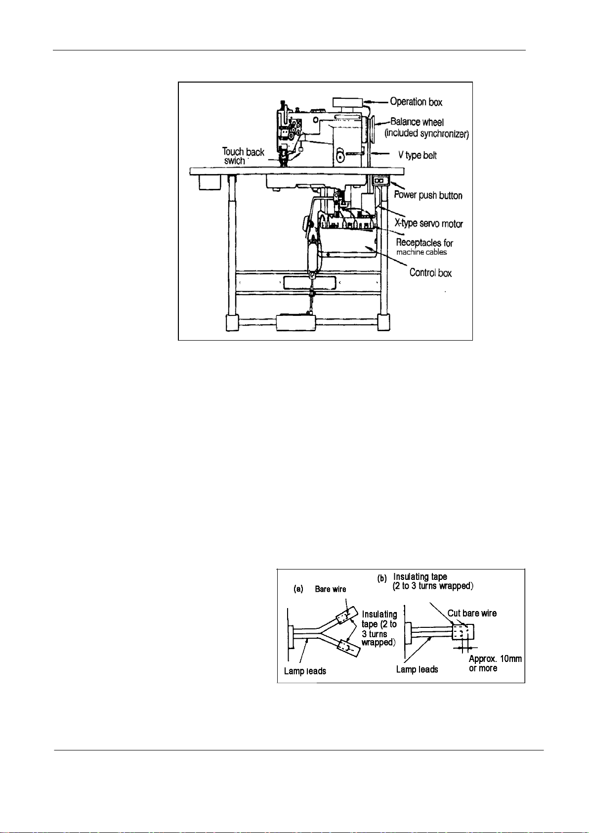
Overall view of assembled
sewing machine
1. Power cable connection
1) Connection to Power Supply
When connecting the power supply connector to the control box, the connector should be completely
plugged in the proper receptacle after confirming the connector type and matching direction.
A. In case of three-phase electrical power system, the “U” phase should be connected to the red lead
he “V” phase to the white lead, and the “W” phase to the black lead. The motor rotary direction
t
depends, however , upon the setting of the internal switch in the control box as described in
Paragraph 1-(3)
CAUTION: The green wire must be connected to the ground terminal in order to ground
the motor properly.
B
he appropriate power fuse capacity is as follows. Power supply 200V-240V: 10A
. T
100V-120V: 15A
2) Lamp Leads
A.
When installing the illuminating lamp(6V,15-20W),The connecting wire is attached on the back of
the Control box. It should be
removed and connected by
removing the insulating tube
from the wire and stripping
properly. The wire connections
,
should be, then, insulated by
wrapping insulating tape on the wires.
CAUTION: The power switch must be Turned off before connecting the lamp.
B. When the illuminating lamp is not used, the end of the lamp leads must be insulated as (a) or (b) as
— 2 —
Page 5
shown in the figure on right side. If a short circuit occurs failing to insulate, the transformer in the
control box will be possibly burned out.
CAUTION: The illuminating lamp must not be connected with any heater, such as a foot
warmer and others, in parallel. Otherwise, the load capacity will be exceeded.
It may cause transformer winding burned out.
3) Rotary direction
I
t is possible to change the rotary direction of the motor by removing the rubber cap from the
bottom left side of the front cover on the control box, and push the internal direction selector switch.
The built-in lamp in the internal switch is off when the motor is rotating counterclockwise as facing
to the motor pulley, and on when rotating clockwise. The rotary direction has been set t
counterclockwise as facing to the motor pulley, matching with the machine prior to shipping.
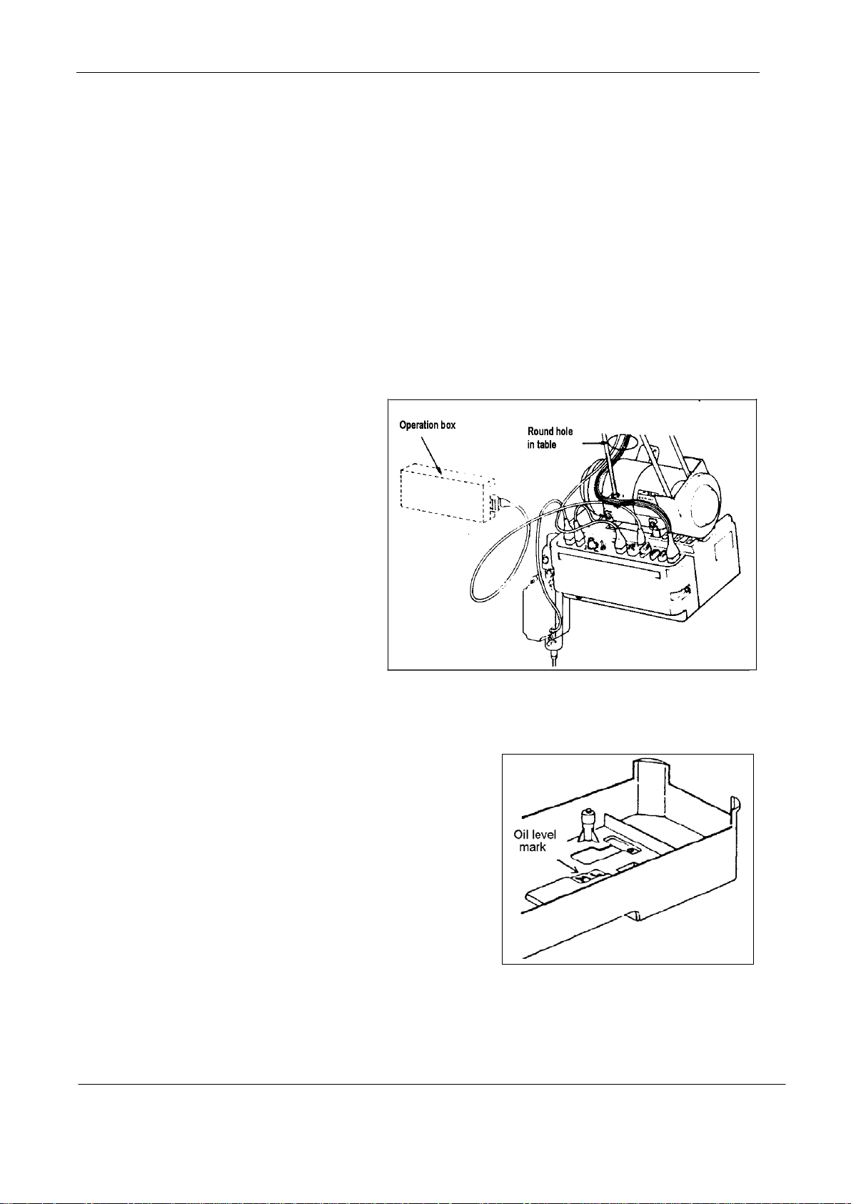
2. Connection of control box
The control box should be connected
as shown to the right.
Note: (1) Be sure to turn the power switch
off for safety before connecting
or disconnecting the connectors.
(2) The combination of the machine
heads with the motor control
panels are specified below.
Use special care for the correct
combination when replacing the machine head or motor control panel
CAUTIONS ON USE
o
.
1. Oiling (1) Fill the oil reservoir with oil up to “H”
mark.Oil level should be periodically checked. If oil level
is found below “L” level replenish oil to “H” level .
For oil, Use white spindle oil
.
2. Oiling (2) When a new sewing machine is used for the first time, or sewing machine left out of use
for considerably long time is used again, replenish a suitable amount of oil to the portions
indicated by arrow in the below figure.
— 3 —
Page 6
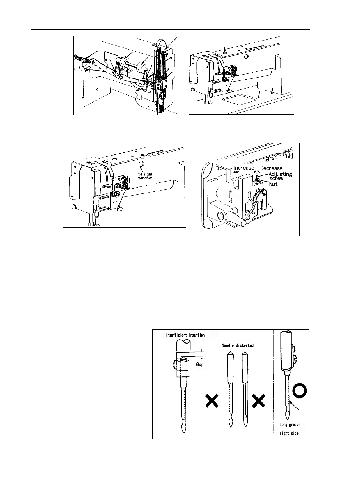
3.
Oiling condition
See dripping of oil through the oil window to check oiling condition during operation.
4. Adjustment of oiling to rotating hook
5. Cautions on operation
a) When the power is turned on or off, keep foot away from the pedal.
b) It should be noted that the brake may not work when the power is interrupted or power failure occurs
during sewing machine operation.
c) Since dust in the control box might cause malfunction or control troubles, be sure to keep the control
box cover close during operation.
d) Do not apply a multimeter to the control circuit for checking; otherwise voltage of multimeter might
damage semiconductor components in the circuit.
OPERATION
1. Installation of needles
Note: Before installing the needles,
be sure to turn off the power.
— 4 —
Page 7
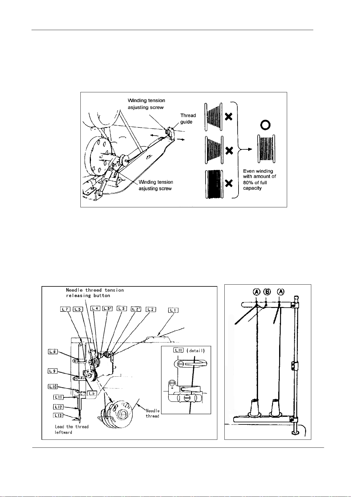
2. Winding of bobbin thread
Note: When bobbin thread is wound, keep the presser foot lifted. Adjustment:
Tension of wound thread Slack winding is recommended for polyester threadand nylon thread.
Conically wound thread Move the thread guide toward smaller diameter of wound thread layer.
Length of wound thread Loosen the thread length adjusting screw to increase length of thread and
tighten the screw to decrease length of thread.
.
3. Threading of needle threads
a) Pass each needle thread through thread guide A
Note: When thin slippery thread (polyester Thread or filament thread, for example) is used pass the
thread through thread guide B as well
ith the take-up lever located at the upper most position, pass each needle thread in the order
b) W
shown in the following figure.
Note: Pressing the upper thread loosening button shown in the figure below opens the saucer of the
upper thread tension adjuster, and the upperthread can easily pulled out.
.
— 5 —
Page 8
4. Setting of bobbin
a) Pulling out 5cm thread tail from the bobbin.
b) Hold the bobbin so that the bobbin thread is would in right direction and put it into the hook.
5. Threading of bobbin threads
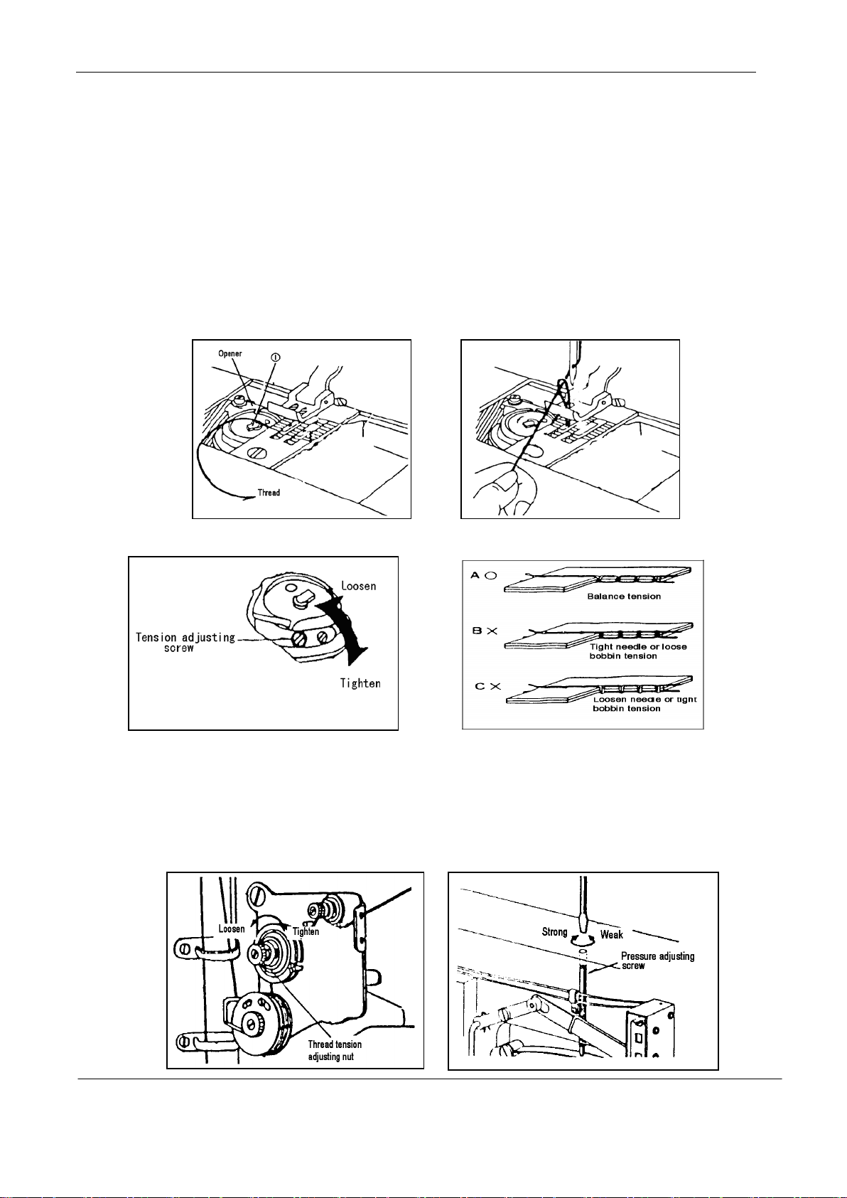
a) Put the hook into the bobbin case and press down the latch ①. The thread end should be left on
the bed .
b) While holding the needle Thread by left hand, rotate the hand-wheel one turn by right hand.
By pulling up the needle thread, as shown in the figure, the bobbin thread will be lifte
Each combination of bobbin thread and needle thread should be aligned and led backward.
6. Tension adjustment of bobbin threads 7. Balance of thread tension
d.
8. Needle thread tension
Needle thread tension should be adjusted in reference to bobbin thread tension.
·
·To adjust needle thread tension, turn each tension adjusting nut
·N
eedle thread tension can be also adjusted for special fabric and thread by changing intensity a
ovable range of slack thread adjusting spring.
m
— 6 —
.
nd
Page 9
9. Adjustment of presser foot pressure
Pressure to fabric(s) can be adjusted by turning the pressure adjusting screw.
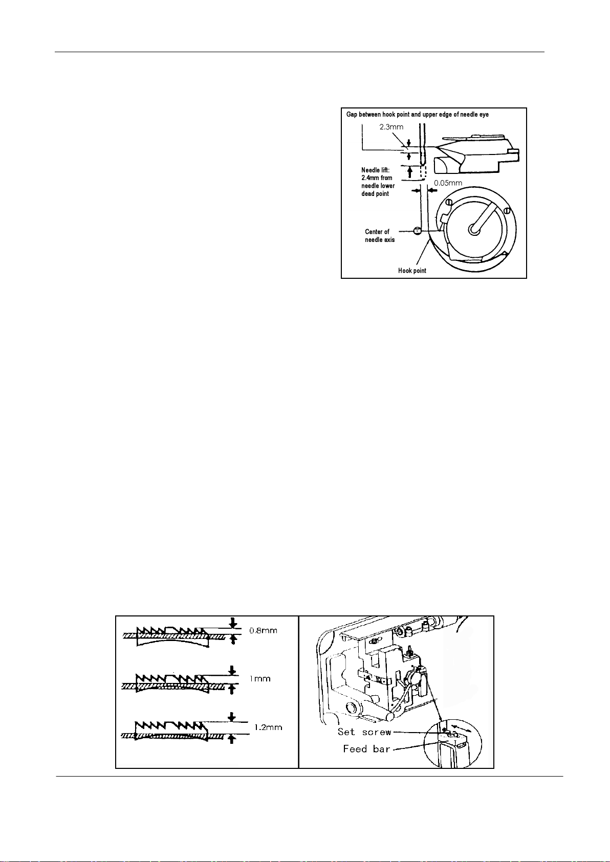
10. Timing between rotating hook motion and
needle motion
(1) Set feed length (stitch length) to “6” on the feed
etting dial.
s
(2) When needle is lifted 2.4mm from the lower dea
poi
nt, as shown in Figure, the following positiona
elationship should be maintained.
r
· The upper edge of needle eye should be 2.3mm
below the hook point
The hook point should be located at the center of needle axis.
·
· Gap between the hook point and the side face of needle s hould be 0.05mm
.
d
l
.
11. Adjustment of feed dog height
Height of feed dog and pressure of presser foot shouldbe adjusted for individual fabric(s) with the
following cautions:
· Fabric will be damaged if the feed dog extends too high,or pressure of presser foot is too large
· Even stitch length cannot be assured if the feed dog is too low or pressure of presser foot is too small.
· Feed dog height should be measured at the point where the needle is at the top position.
For light fabrics …… Approx. 0.8mm from throat plate
For usual fabrics …… Approx. 1.0mm from throat plate
For heavy fabrics …… Approx. 1.2mm from throat plate
.
Adjustment procedure
a) Lean the machine head backward.
b) Turn the hand wheel by hand and stop when the feed dog rises to the maximum height.
c
) Loosen the feed bar set screw.
d) V
e) After the adjustment, tighten the feed bar set screw.
ertically move the feed bar (in the direction indicated by arrow in the figure) to adjust it to
adequate height
The feed dog height is factory-adjusted to 1.2mm
.
— 7 —
Page 10
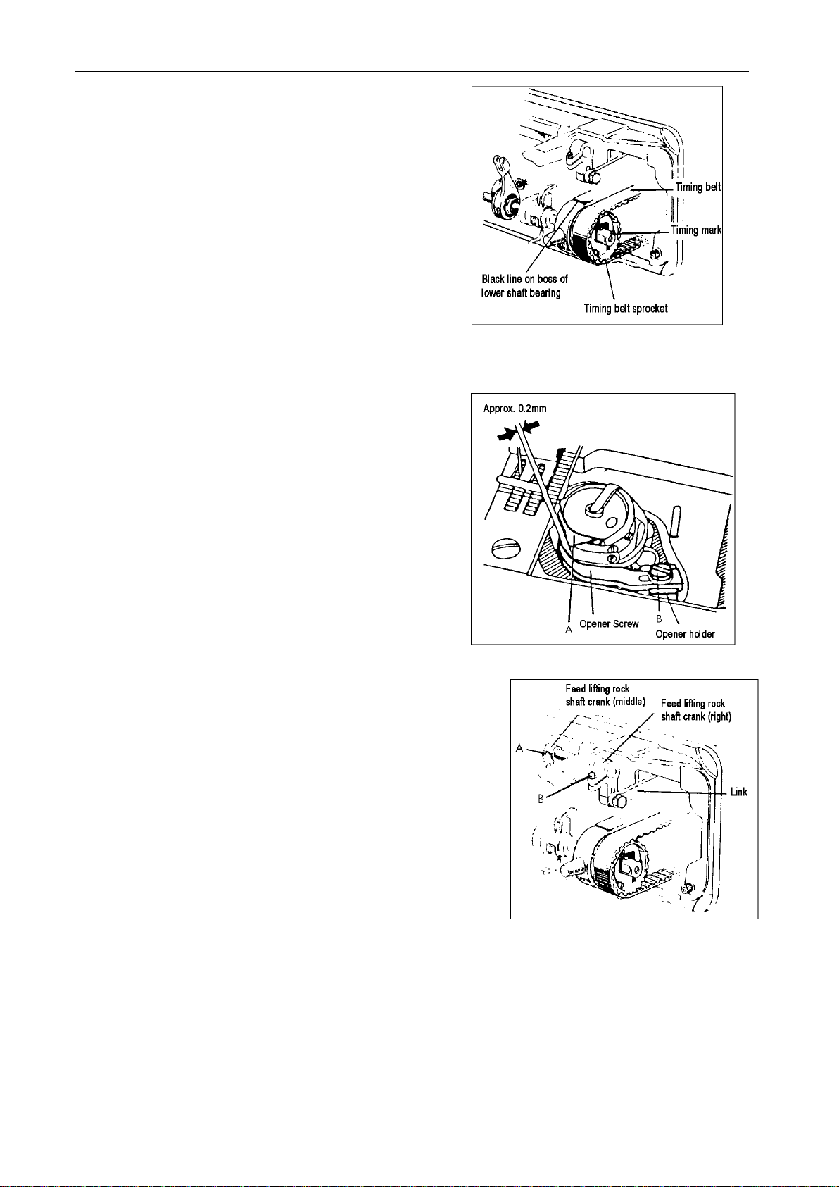
12. Relationship between rotating hook
motion and take-up lever motion
When the timing belt (toothed belt) was removed for
its replacement, for example, the relationship between
rotating hook motion and take-up lever motion should
be adjusted as follows:
a) Turn the balance wheel and stop when the take-up
lever is lifted to its upper dead point.
b) Lean the machine head backward and make sure the
arrow (timing mark) put on the timing belt is in line with the black line on the boss of lower shaft bearing.
c) If the timing mark is not in line with the black line ,remove the timing belt and install it again to
adjust.
13. Relationship between hook motion
and opener motion
a) Turn the balance wheel by hand and stop when
the opener holder is located most remotely from
the throat plate.
b) Make sure gap between the bobbin case holder A
and the opener is approximately 0.2mm.
c) If the gap is too large or small , loosen the opener
holder set screw B and adjust position of the opener.
14. Relationship between needle motion and feed dog motion
a) Set feed length to “0” on the feed setting dial
b) Lean the machine head backward.
c) Loosen the feed lifting rock shaft crank set screws A and B.
d) Set the needle at the lowest position.
e) Adjust the distance between presser rod and vibrati
prevention rod to 9mm and temporarily tighten the feed
lifting rock shaft crank set screws A and B
f) Check that the right feed lifting rock shaft crank is
connected with the link at right angle, as shown in Figure.
g) If the connection is not at right angle, remove the back cover, loosen screw C and move the right link
.
on
to connect the right feed lifting rock shaft with the link at right angle.
h) After the completion of adjustment, fully tighten the screws A , B and C.
At this time make certain that needle can enter the feed dog needle hole at the center of the hole.
— 8 —
Page 11
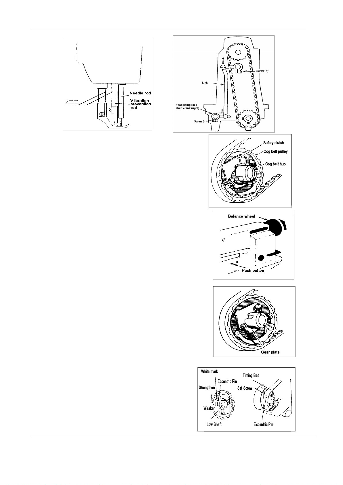
15. Safety clutch device:
Safety clutch device is installed to prevent the hook
and cog belt from damage in case the thread is
caught into the hook when the machine is loaded
abnormally during operation.
(1) Function of safety clutch.
a) When the safety clutch acts, the cog belt pulley will be
unloaded. then the rotation of hook shaft will stop.
The arm shaft only will rotate. Stop the operation of machine.
b) Clean the thread thoroughly which is caught into the hook.
c) Turn the cog belt hub by hand, and check whether the hook
Shaft rotates lightly and properly, place the clutch device
as follows.
(2) How to set the safety clutch.
a) While pressing down the push button on the opposite side
of bed by left hand, turn the balance wheel slowly by
right hand away from you as shown in the figure.
b) The balance wheel will stop by the gear plate,
but turn the balance wheel more firmly.
c) Release the push button.
d) As shown in the Figure, the safety clutch device is set.
(3) Force applied to the safety clutch.
a) The force applied to the safety clutch is the
smallest when the white mark of the eccentric pin faces
the center of the lower shaft. The force proportionally
increases as the white mark faces the outside.
— 9 —
Page 12

b) To adjust the force slide the timing belt, loosen the set screw, and turn the eccentric pin.
Model
GC20618-1E
Application
Heavy material
Max. sewing speed
1800rpm
Thread take-up lever stroke
74.5mm
Needle-bar stroke
36mm
Presser-foot stroke
16mm by Leg 8mm by hand
Needle No.
DP×17 18#-23#
Lubrication system
Automatic lubrication
Motor
Clutch motor 370W
c) After the adjustment, make sure to fasten the set screw.
16. Upper feed adjustment (Needle side)
If the uneven feeding occurs according to the fabric,
Adjust the long hole of the horizontal feed shaft crank
(right) to adjust the upper feed length. (How to adjust)
a) Loosen the special bolt.
ove the special bolt upward to decrease upper feed.
b) M
c) Move the special bolt downward to increase the upper feed. The upper feed and the lower f
t
heoretically becomes equal at the reference line on the horizontal feed shaft crank.
d) Securely tighten the special bolt after adjustment.
17. Outside presser foot and inside presser vertical stroke adjustment
When fabric with large elasticity is sewn, or when thickness of fabric changes, the vertical stroke
(movable range) of the presser feet should be adjusted as follows:
Adjustment
a) Loosen the special bolt.
b) The vertical strokes of the presser feet becom
m
aximum when the crank rod is moved upward and set
c) T
he vertical strokes becomes minimum when the nut
is moved downward and set.
d) A
fter the adjustment, fully tighten the special bolt.
The vertical strokes of the presser feet can be adjusted within a range from 6mm to 2mm.
e
.
SPECIFICATIONS
eed
Stitch length
Vertical stroke of upper feed
Edge binder 8mm(Standard)
— 10 —
0~10mm
2~6mm
Page 13

A.ARM BED AND ITS ACCESSORIES
— 11 —
Page 14

A.ARM BED AND ITS ACCESSORIES
Fig.
No.
A01
A02
A03
A04
A05
A06
A07
A08
A09
A10
A11
A12
A13
A14
A15
A16
A17
A18
A19
A20
A21
A22
A23
A24
A25
A26
A27
A28
A29
A30
A31
A32
A33
A34
A35
A36
A37
A38
A39
A40
Part No. Description Pcs. Remarks
HA300B2090
HA300B2170
H4716B8001
H4717B8001
H4715B8001
H4718B8001
H2000B2010
H4719B8001
HA700B2060
H2400B2100
HA307B0673
H2000M0080
HM41B98001
HN11B28001
HM41B88001
HN11B18001
HM32B47101
H3200I2030
H415040060
HN11B38001
H4722E8001
HA719B7011
HN10B88001
H5332B8001
HN10B98001
HA300B2190
H4732B8001
H4722B8001
H4723B8001
H4724B8001
H4725B8001
H3200B2100
H3000D2160
H4726B8001
H4727B8001
H2400B2080
H2400B2070
H4730B8001
H2400B2060
H3200B2060
Rubber plug 2
Screw 15 SM11/64(40)×8
Oil guard plate 1
Thread take-up cover 1
Rubber plug 1 φ13
Side cover (left) 1
Rubber plug 1 φ13
Side cover (right) 1
Screw 2 SM11/64(40)×8
Thread guide 1
Rubber plug 1
Cap 2
Screw 1
Screw 1
Lever 1
Single needle binders mounting plate 1
Single needle binders 1
Washer 2
Screw 2
Mounting plate 1
Washer 1
Screw 1
Side cover 1
Screw 3
Needle plate 1
Screw 2 SM11/64(40)×8
Slide plate 1
Screw 1 SM1/8(44)×3
Spring 1
late 1
P
Thread guide 1
Screw 1 SM9/64(40)×6.5
Screw 1 SM9/64(40)×6.5
Thread guide (middle) 1
Face plate 1
Screw 2 SM3/16(28)×11
Thread guide (upper) 1
Guide mounting plate 1
Plate for oil guard 1
Oil guard 1
— 12 —
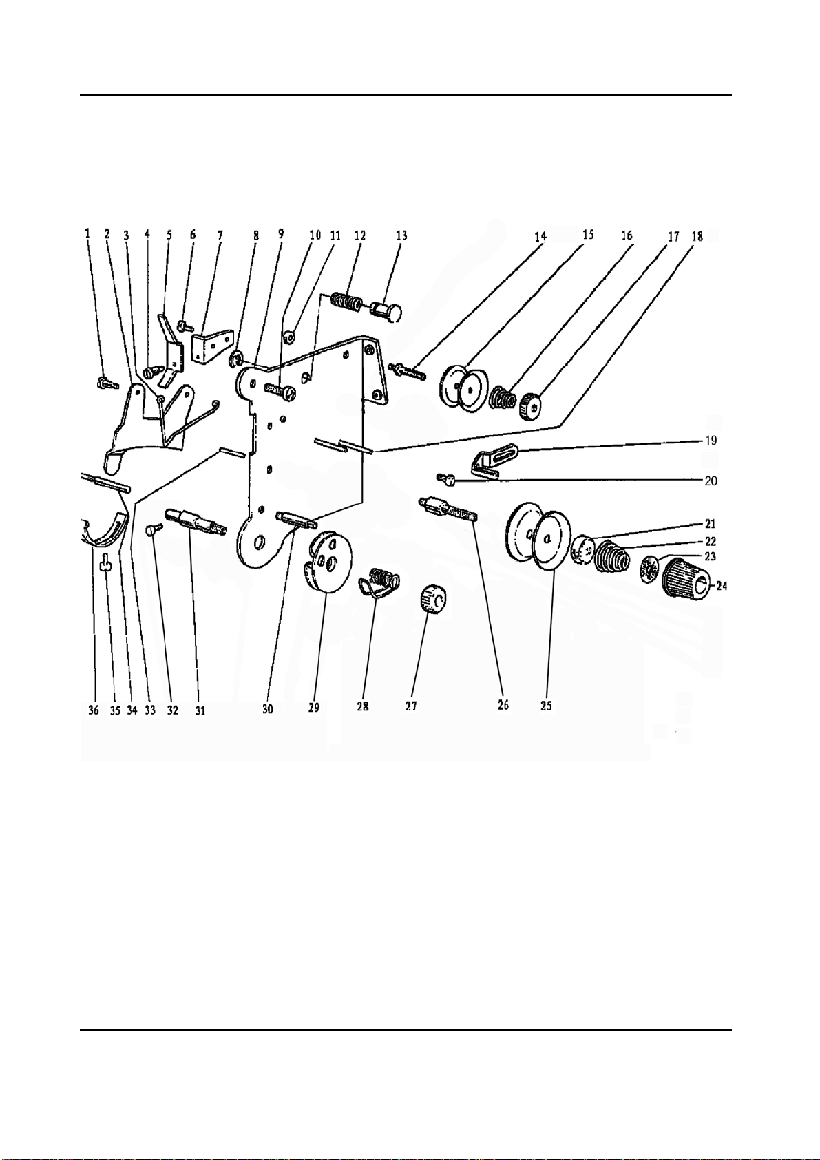
Page 15
B.THREAD TENSION REGULATOR MECHANISM
— 13 —
Page 16

B.THREAD TENSION REGULATOR MECHANISM
Fig.
No.
B01
B02
B03
B04
B05
B06
B07
B08
B09
B10
B11
B12
B13
B14
B15
B16
B17
B18
B19
B20
B21
B22
B23
B24
B25
B26
B27
B28
B29
B30
B31
B32
B33
B34
B35
B36
Part No. Description Pcs. Remarks
H3221B6811
H3221B3142
H3221B6812
H4705C8001
H4706C8001
HA7311C306
H4707C8001
H007013050
H3221B6820
HA300C2030
H3221B6810
H4708C8001
H4709C8001
H3221B0683
HA112B0693
H3221B0684
HA710B0671
H3221B0682
H3306B0661
HA106B0676
HA310B0702
H4710C8001
HA115B7010
HA310B0701
HA310B0705
H3221B0686
H32481B721
H4713C8001
H32481BD21
H4804C8001
H4805C8001
H3230K0751
H3221B6817
H3221B6818
H3200B2100
H3221B6819
Screw 2 SM9/64(40)×3
Tension releasing pl ate 1
Tension releasing spring 1
Screw 1 SM9/64(40)×4.2
Lever 1
Screw 1 SM9/64(40)×4.5
Mounting plate 1
Stop ring 1 GB/T896 5
Mounting plate 1
Screw 2
Nut 1 SM11/64(40)
Spring 1
Push button 1
Thread tension stud 1
Thread tension disk 2
Thread tension spring 1
Thumb nut 1
Pin 2
Thread guide 1
Screw 1 SM9/64(40)×6
Thread tension rel eas ing plate 1
Thread tension spring 1
Thumb nut revolution stopper 1
Thumb nut complete 1
Thread tension disk 2
Thread tension stud 1
Thumb nut 1 SM1/4(40)
Thread take-up spring 1
P
late complete 1
Screw 1
Thread tension stud 1
Screw 1 SM11/64(40)×10
Pin 1
Tension releasing pin 1
Screw 1 SM9/64(40)×6.5
Stopper 1
— 14 —
Page 17

C. ARM SHAFT MECHANISM
— 15 —
Page 18

C.ARM SHAFT MECHANISM
Fig.
No.
C01
C02
C03
C04
C05
C06
C07
C08
C09
C10
C11
C12
C13
C14
C15
C16
C17
C18
C19
C20
C21
C22
C23
C24
C25
C26
C27
C28
C29
C30
C31
C32
Part No. Description Pcs. Remarks
HA307C0662
H4706D8001
HA105D0662
HA100C2060
HA100C2070
H32111B204
H4708D8001
H32111B104
H4709D8001
H3205C0661
HA113F0684
H3205C1021
HA100F2130
H3205J0662
H3205J0661
HA113F0684
HF60D58001
HA110D0672
H3200C2030
H4713D8001
H4714D8001
H4715D8001
H007013025
H4716D8001
H4717D8001
H4718D8001
H4719D8001
H4720D8001
H4721D8001
HA104F0654
H4722D8001
H4723D8001
Set screw 1 SM1/4(40)×7
Crank 1
Screw 1 SM1/4(40)×3.5
Set screw 1 SM9/32(28)×14
Screw 1 SM9/32(28)×13
Arm shaft bushing (left) 1
Screw 1 SM1/4(24)×13
Felt 1
Arm sha ft 1
Spring flange 3
Screw 1 SM15/64(28)×8.5
Belt pulley (upper) 1
Screw 1 SM15/64(28)×14.5
Bearing 1
Collar 1
Screw 2 SM15/64(28)×8.5
Pulley 1
Screw 2 SM11/64(28)×12
Cog belt 1
Spring plate 1
Pin 1
Link 1
E-type stop ring 1 GB/T896 2.5
Twist spring 1
Plate 1
Pin 1
te 1
Pla
Bushing 1
Screw 1 SM15/64(28)×10.5
Screw 1 SM15/64(28)×10
Belt pulley (lower) 1
Screw 2 SM15/64(28)×4.5
— 16 —
Page 19

D.UPPER SHAFT & PRESSER FOOT MECHANISM
— 17 —
Page 20

D.UPPER SHAFT & PRESSER FOOT MECHANISM
Fig.
No.
D01
D02
D03
D04
D05
D06
D07
D08
D09
D10
D11
D12
D13
D14
D15
D16
D17
D18
D19
D20
D21
D22
D23
D24
D25
D26
D27
D2
D29
D30
D31
D32
D33
D34
D35
D36
D37
D38
D39
D40
D41
D42
D43
Part No. Description Pcs. Remarks
Feed lifting rock shaft 1
Screw 2 SM1/4(24)×7
Bushing 2
Nut 1 M6×0.75
Lever 1
Screw 1 SM1/4(28)×16
Washer 1
Connecting rod 1
Bolt 1
Oil pipe & wick complete 1
Spring 1
C-type stop ring 1 GB/T894.1 25
Eccentric 1
Screw 2 SM1/4(40)×6
Screw 1 SM1/4(24)×14
Knee lifter lifting lever complete 1
Snap pin 1
Operation rod 1
Collar 1
Screw 1 SM11/64(40)×5.5
Screw 1 SM1/4(24)×17
Lever spring 1
Screw 1 SM15/64(28)×79
Twist spring 1
Knee lifting lever 1
Screw 1 SM1/4(24)×7
Nut
Screw 1 SM1/4(24)×19
Screw 2 SM11/64(40)×12
Guide 1
Bushing 1
Presser bar 1
Screw 1 SM1/8(44)×9
Spring bracket 1
Thread releasing plate 1
Screw 1 SM9/64(40)×8.5
Lifter lever 1
Spring 1
Bracket 1
Screw 1 SM11/64(40)×8.5
Bell crank 1
Support shaft 1
Roller 1
1
8
H4705E8001
H4706E8001
H4707E8001
HS91165206
H4709E8001
H3115F0671
H2013J0065
H2014J0066
H2000J2100
H4713E8001
H20111C106
H007009250
H4714E8001
HA307C0662
H4732E8001
H4735E8001
H4739E8001
H4738E8001
H4741E8001
H4742E8001
H3100G2170
H4730E8001
H4729E8001
H4727E8001
H4728E8001
H3100G2130
H4726E8001
H4725E8001
HA111G0683
H4723E8001
H4744E8001
H4754E8001
H3200E2020
H4746E8001
H4768E8001
H2404I0034
H4748E8001
H4767E8001
H4752E8001
H4749E8001
H4715E8001
H2004J0655
H4717E8001
— 18 —
Page 21

D.UPPER SHAFT & PRESSER FOOT MECHANISM
Fig.
No.
D44
D45
D46
D47
D48
D49
D50
D51
D52
Part No. Description Pcs. Remarks
H4718E8001
H2004J0662
H4719E8001
HA100E2150
H4722E8001
H4721E8001
H4753E8001
H4708D8001
HN10E48001
Screw 1 SM11/64(32)×6
Screw 1 SM1/4(40)×5
Link 1
Screw 2 SM11/64(40)×10
Washer 2
Bell crank guide 1
Screw 1 SM11/64(40)×14.5
Screw 2 SM1/4(24)×13
Lifting presser foot 1
— 19 —
Page 22

E.NEEDLE BAR & THREAD TAKE-UP LEVER MECHANISM
— 20 —
Page 23

E.NEEDLE BAR & THREAD TAKE-UP LEVER MECHANISM
Fig.
No.
E01
E02
E03
E04
E05
E06
E07
E08
E09
E10
E11
E12
E13
E14
E15
E16
E17
E18
E19
E20
E21
E22
E23
E24
E25
E26
E27
E28
E29
E30
E31
E32
E33
E34
E35
E36
E37
E38
E39
E40
E41
E42
E43
Part No. Description Pcs. Remarks
H24211DN05
H4706F8001
H4707F8001
HA100C2020
H24211DN05
H24211DM05
H4712F8001
H2405D1112
H24211D405
H24211D305
HA110D0672
H2405D0662
H4716F8001
H4717F8001
H4719F8001
H32111D304
H4721F8001
H3204D6513
H4722F8001
H32111D604
H4806F8001
H4725F8001
H3400C2020
H3200I2030
H3400C2010
H4726F8001
H4753E8001
H4728F8001
H4729F8001
H4730F8001
H3410C301P
H3406C0671
H3406C0672
H602040240
H4734F8001
H4736F8001
H3204B0652
H2012N0652
H3407C0661
H32311D506
H3407C0662
H32311D306
H32311D406
Oil wick 1
Needle bar guide bracket s tud 1
Screw 1 SM5/16(28)×10.4
Screw 1 SM15/64(28)×10
Oil wick 1
Thread take-up lever support stud 1
Thread take-up lever 1
Thread take-up slide brock 1
Oil wick 1
Plug 1
Screw 1 SM15/64(28)×12
Needle bar crank pin 1
Oil wick 1
Connecting link 1
Needle bar guide bracket 1
Screw 6 SM3/32(56)×4
Spacer 2
Felt 1
Needle bar holder 1
Screw 1 SM9/64(40)×8.5
Needle bar 1
Vibrating press er bar 1
Screw 1
Washer 1
Needle bar guide 1
Vibrating presser bar link 1
Screw 2 SM11/64(40)×17.5
Vibrating presser bar guide 1
S
pring 1
Vibrating presser spring guide 1
Square block 1
Crank pin 1 SM15/64(28)×10
Needle bar vibratin g crank (left) 1
Taper 1 GB/T117 4×24
Collar 1
Needle bar vibratin g shaft 1
Needle bar vibrating shaft bushing 2
Screw 1 SM1/4(24)×16
Needle bar vibratin g crank (right) 1
Nut 1
Connecting link 1
Screw 1 SM5/16(24)
Oil wick 1
— 21 —
Page 24

E.NEEDLE BAR & THREAD TAKE-UP LEVER MECHANISM
Fig.
No.
E44
E45
E46
E47
E48
E49
Part No. Description Pcs. Remarks
H3129F0691
HA100C2170
H3129F0693
H4740F8001
HA700F2100
HN10F48001
Screw 1 SM3/32(56)×2.5
Screw 1 SM1/8(44)×4.5
Thread guide 1
Needle 1
Screw 1 SM11/64(40)×7
Presser loot complete 1
— 22 —
Page 25

F.LOWER SHAFT & FEED ROCK SHAFT MECHANISM
— 23 —
Page 26

F.LOWER SHAFT & FEED ROCK SHAFT MECHANISM
Fig.
No.
F01
F02
F03
F04
F05
F06
F07
F08
F09
F10
F11
F12
F13
F14
F15
F16
F17
F18
F19
F20
F21
F22
F23
F24
F25
F26
F27
F28
F29
F30
F31
F32
F33
F34
F35
F36
F37
F38
F39
F40
F41
F42
F43
Part No. Description Pcs. Remarks
H4706H8001
H4707H8001
HF60H48001
HN10H58001
HN10H68001
H4712H8001
H007013050
H4714H8001
HF60H78001
HF61H08001
H2405D0664
H4719H8001
HF62H48001
H007009260
HF60H97101
HF60H87101
H4722H7101
H4725H8001
HA105D0662
H3205H0654
H4723H8001
H4727H8001
HA7311C306
H4729H8001
H4728H8001
H003055060
H4731H8001
H2012N0652
HA100G2120
H4708D8001
HA108G0661
HA105D0662
H4736H8001
H2012N0652
HA304G0656
H3204G0651
H4740H8001
HA104G0012
H3205G1032
H3204G0031
H3200G2030
H3205G0662
HF62H68001
Lower shaft bushing (left) 1
Oil wick 1
Lower shaft 1
Feed eccentric cam 1
Screw 1 SM1/4(40)×4.3
Lower shaft bushing (right) 1
Stop ring 4 GB/T896 5
Spring 2
Push button 2
Stopper 1
Screw 4 SM15/64(28)×14
Bearing 1
Feed connecting rod 1
Stop ring 1
Feed ragulator comp 1
Feed connecting rod comp 1
Lower shaft bushing complete (middle) 1
Bushing 1
Screw 1 SM1/4(40)×4
Screw 1 SM1/4(40)×5
Ball bearing 1
Bearing holder 1
Screw 3 SM9/64(40)×7
Screw 1 M6
Washer 1
Nut 1 GB52008 M6
Feed connection crank (right) 1
Screw 1 SM1/4(24)×16
Feed rock shaft bushing 2
crew 2 SM1/4(24)×13
S
Collar 2
Screw 4 SM1/4(40)×4
Feed connection crank (middle) 1
Screw 1 SM1/4(24)×16
Screw 1 SM3/16(28)×15
Feed rock shaft 1
Felt 2
Screw 2 SM3/16(28)×12
Feed connectio n crank (left) 1
Oil wick 1
Clip 1
Oil wick 1
Shaft for feed connecting rod 1
— 24 —
Page 27

F.LOWER SHAFT & FEED ROCK SHAFT MECHANISM
Fig.
No.
F44
F45
F46
F47
F48
F49
F50
F51
F52
F53
F54
Part No. Description Pcs. Remarks
H32243G205
H3205G0662
H429050050
H4805H8001
HN10H87101
H32211G205
H3200H2040
H2013J0065
H3205H0653
H3205H0652
H4743H8001
Feed bar shaft 1
Oil wick 1
Bolt 1 GB/T78 M5×5
Feed bar 1
Feed dog 1
Bolt 2 SM1/8(40)×7
Screw 1 SM15/64(28)×17
Washer 1
Screw 1 SM1/8(44)×4
Felt 1
Feed bar forked connection 1
— 25 —
Page 28

G.HOOK SADDLE MECHANISM
— 26 —
Page 29

G.HOOK SADDLE MECHANISM
Fig.
No.
G01
G02
G03
G04
G05
G06
G07
G08
G09
G10
G11
G12
G13
G14
G15
G16
G17
G18
G19
G20
G21
G22
G23
G24
G25
G26
G27
G28
Part No. Description Pcs. Remarks
H3304I0651
H3207I0661
H3207I0662
H33121I104
H33121I204
H33131I204
H4708I7101
H3306I0067
H3204I0656
H32153I204
H32153I504
H33131I104
H005008050
HA104G0658
H2004J0067
H3200I2030
H3305I0066
H4707I8001
H4706I8001
H4708I8001
H4705I8001
H4709I8001
H3204I0653
H3204I0658
H3204I0659
H2013J0065
H3200I2050
H3204I0657
Hook saddle (left) 1
Screw 1 SM15/64(28)×22
Bushing 1
Hook shaft bushing (upper) 1
Washer 1
Link 1
Hook complete 1
Bobbin 1
Oil wick 2
Screw 1 SM3/16(32)×7.8
Opener bracket shaft 1
Opener bracket 1
Spring washer 1 GB/T93 5
Nut 1
Screw 1
Washer 1
Opener 1
Screw 3 SM1/4(40)×4
Hook driving gear (large) 1
Screw 1 SM1/4(40)×6.5
Hook driving gear (small) 1
Screw 1 SM1/4(40)×5
Hook shaft bushing (lower) 1
Screw 1
Nut 1
Washer 1
Screw 1 SM1/4(24)×23
Screw 1
SM3/16(
28)×14.5
— 27 —
Page 30
H.OIL LUBRICATION MECHANISM
— 28 —
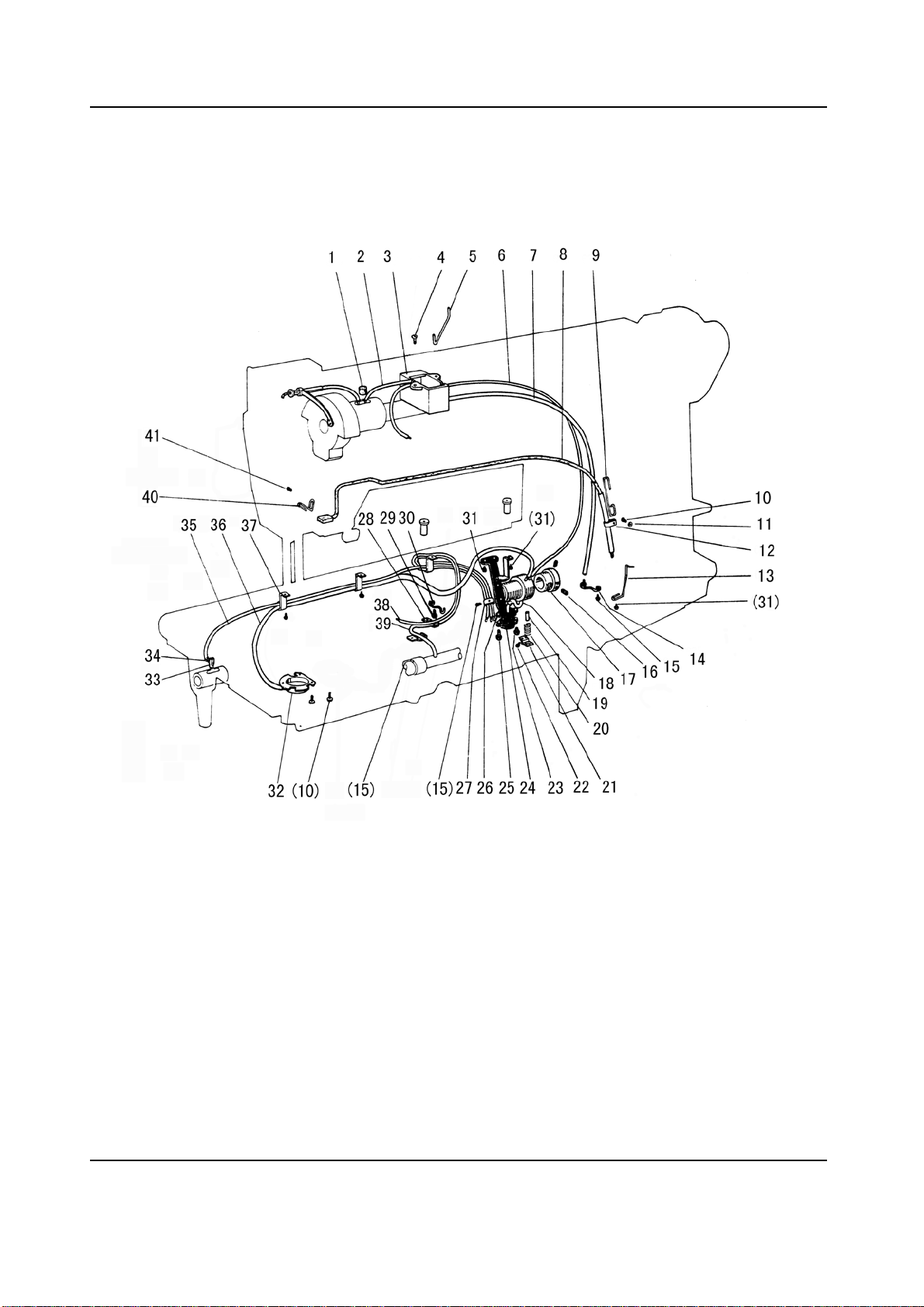
Page 31

H.OIL LUBRICATION MECHANISM
Fig.
No.
H01
H02
H03
H04
H05
H06
H07
H08
H09
H10
H11
H12
H13
H14
H15
H16
H17
H18
H19
H20
H21
H22
H23
H24
H25
H26
H27
H28
H29
H30
H31
H32
H33
H34
H35
H36
H37
H38
H39
H40
H41
Part No. Description Pcs. Remarks
H32175B304
H4705J7101
H3204K0011
H411040160
H4707J8001
H4708J8001
H4709J8001
H4711J7101
H4713J8001
HA7311CC06
HA100I2050
H2000M0110
H4714J8001
H4715J8001
HA106B0676
H3230K0751
H4716J8001
H3215K0696
H1100I2070
H1100I2090
H1100I2110
H3204D6510
H3215K0693
H3215K0692
H3215K0694
H4718J7101
H3215K0695
H3200K0170
HA7311CC06
H3210K0674
HA100E2150
H3211K0068
H2000M0110
H3200K0180
H4735J8001
HM90M48001
H3200K0160
H4725J7101
H4728J7101
H4731J8001
HA300C2030
Felt 1
Oil pipe complete 1
Oil reservoir complete 1
Screw 2 GB/T819.1 M4×16
Holder 1
Oil pipe Ф3×1×400 1
Oil pipe Ф5×1×360 1
Oil reservoir complete 1
Holder 1
Screw 4 SM9/64(40)×6.5
Spring washer 1
Holder 1
Holder 1
Holder 1
Screw 8 SM9/64(40)×4.5
Screw 2
Bushing 1
Oil pipe 1
Pin 1
Spring 1
Spring holder 1
Screw 1 SM1/8(44)×4.5
Screw 1 SM9/64(40)×5
Filter 1
Screw 1 SM9/64(40)×7
Mounting plate complete 1
Holder 1
Holder 1
Screw 1 SM9
Holder 1
Screw 4 SM11/64(40)×9
Oil reservoir complete 1
Holder 3
Oil wick Ф2.5×35 3
Oil pipe 1
Oil pipe Ф3×1×535 1
Holder 3
Oil wick 1
Oil wick 1
Holder 1
Screw 1
/64(40)×6.5
— 29 —
Page 32

I.ACCESSORIES
— 30 —
Page 33

eat
I.ACCESSORIES
Fig.
No.
I01
I03
I05
I06
I07
I08
I09
I10
I11
I12
I13
I17
I18
I19
I22
I24
I27
I28
I29
I30
I31
I32
I33
I34
I35
I36
I37
I38
I39
I40
I41
I42
I43
I44
I45
I46
I47
Part No. Description Pcs. Remarks
H4740F8001
H3208L8001
H3306I0067
H3200L0050
H801045200
H4700K0020
H4700K0030
HA100J2110
HA100J2140
HA100J2150
H3207L0065
HA300J2170
HA200J2030
H3300L0040
HA300J2280
HH404I7101
HA100J2120
HA307J0067
HA300J2070
H3214L0067
H3214L2011
H3213L0662
HA104J0657
HA106J0664
HA104J6510
HA104J0659
H3213L0664
H007013090
HA104J0653
HA104J0652
H3213L0661
HA100J2180
H7323H8001
H7320H7101
H801055250
HA300J2230
H7326H8001
Needle DP×17-23 3
Socket wrench 1
Bobbin 2
Screw 2
Vibration preventing rubber 4 GB/T99 4.5×20
Vibration preventing rubber 2
Vibration preventing rubber 2
Oiler 1
Screw driver (middle) 1
Screw driver (small) 1
Thread a needle kit 1
Oil can 1
Cotton stand 1
Bobbin winder 1
Screw 2 SM11/64(28)×8
Belt cover complete 1
Magnet block for reservoi r 1
Hinge complete 2
Screw driver (large) 1
Small parts 1
Knee lifter pin 1
Knee lift shaft 1
Spring 1
Bolt 1
Nut 2
Screw 2
Knee lifter crank 1
E-type stop ring 1 GB/T896 9
Washer 1
Screw 1
Oil reservoir 1
Vinyl cover 1
Shelf 1
Plate complete 1
Screw 2
Washer 1
S
1
— 31 —
Page 34

2010.9. Printed
 Loading...