

Highlead GC20618 User Manual
Purchasing
Copy
Dept
HIGH
LEAD
GC20618 Series
Compound-Feed,Heavy
Lockstitch Sewing
Machine
Material
Instruction
Parts
SHANGHAI HUIGONG
N0.3
Manual
Catalog
SEWING MACHINE FACTORY

PARTS
1.
2.
3.
4.
5.
6.
7.
8.
9.
10.
11.
12.
13.
CATALOG
Arm bed
Thread tension regulator mechanism-----------------------------------------------------------
Arm shaft
Upper shaft & presser foot mechanism
Needle bar & thread take-up lever mechanism
Stitch regulator mechanism
Lower shaft & feed rock shaft
Hook saddle mechanism
Knife mechanism ( I ) ----------------------------------------------------------------------- 3 7
Knife mechanism
Touch back mechanism & detector mechanism
Oil lubrication mechanism
Accessories------------------------------------------------------------------------------------
its
accessories
mechanism--------------------------------------------------------------------------
------------------------------------------------------------------------
-------------------------------------------------------
------------------------------------------------
------------------------------------------------------------------mechanism-----------------------------------------------------
----------------------------------------------------------------------
(II)
------------------------------------------------------------------------
-----------------------------------------------
--------------------------------------------------------------------
17
19
22
24
27
30
32
35
39
42
44
47
GAlJGIC
J>ARTS
LIJ\T
-------------------------------------------------------------------------
50
CONTENTS
PRECAUTIONS
PREPARATION
I.
Power cable connection
2.
Connection
3.
Adjustment
BEFORE
FOR
of
control box
of
needle bar stop position
STARTING OPERATION--------------------------------------I
OPERATION
-----------------------------------------------------------------------2
----------------------------------------------------------------------3
---------------------------------------------------------3
CAUTIONS ON USE
I.
Oiling
(I)
---------------------------------------------------------------------------------------4
2.
Oiling (2)
3.
Oiling condition
4.
Adjustment
5.
Cautions on operation
---------------------------------------------------------------------------------------4
---------------------------------------------------------_:
of
oiling
to
rotating hook
--------------------------------------------------------------------------5
-----------------------------------------------------------5
OPERATION
1.
Installation
2.
Winding
3.
Se
I ection
4.
Threading
5.
Adjustment
6.
Setting
7.
Threading
8.
Tension adjustment
9.
Balance
10.
Needle thread tension
1I. Adjustment
12.
Timing between rotating hook motion and needle motion
13.
Adjustment
I4. Relationship between rotating hook motion and take-up lever motion
15.
Relationship between hook motion and opener motion
16.
Relationship between needle motion and feed dog motion
17.
Safety clutch device
I8. Upper feed adjustment (needle
19.
Outside presser foot and inside presser vertical stroke adjustment
20.
Adjustment
21.
Installation
22.
Adjustment
23.
Adjustment
24.
Adjustment
25.
Sharpening
26.
Adjustment for change
of
needles----------------------------------------------------------------------------
of
bobbin thread
of
thread
of
needle threads
of
feed (stitch) length and stitch reversing (touch-back)
of
bobbin
of
bobbin threads
of
thread tension
of
presser foot pressure --------------------------------------:-----------------------8
of
feed dog height
of
forward/backward stitch length
of
movable knife
of
thread trimmer
of
needle threads tension release assembly
of
scissoring pressure
of
fixed knife
-------------------------------------------------------------------------------7
-----------------------------------------------------------------------5
------------------------------------------------------------------------------
---------------------------------------------------------------~----6
--------------------------------------------------------------------7
of
bobbin threads
----------------------------------------------------------------------
---------------------------------------------------------------------------8
--------------------------------------------------------------------------
side)---------------------~-------------------------------------
-----------------------------------------------------------------
cam-------------------------------------------------------------
----------------------------------------------------------------------
of
needle
----------------------------------------------------------8
--------------------------------------8
-----------------------------------------------------------------9
---------------------------------------
------------------------------------
------------------------------------------------
----------------------------------------
of
movable knife and fixed
to
needle distance--------------------------------------------
______________________
----------------------------7
------------------------
----------------------------
knife---------------------------
4
5
6
8
IO
I 0
I 0
II
12
I2
I2
I3
13
I4
I4
15
15
SPECIFI<:ATIONS ------------------------------------------------------------------------------
16
PRECAUTIONS
1.
Safety precautions
BEFORE
STARTING OPERATION
I) When turning the
needle and the area
Power
2)
3) The power must be
4) Avoid placing fingers, hairs, bars etc. near the pulley,
5) Do not insert fingers into the thread take-up cover,
6)
2.
Precaution before Starting Operation
I) If
2) If the machine
3) When a new sewing machine is first turned on, verify the rotational direction
must be turned
adjusting the machine,
when the machine is operation. Injury could result.
machine
If
these safety devices.
is
in operation.
a belt cover, finger guard,
the machine's oil pan has an oil sump, never operate the
power
on, keep your hands and fingers
around
turned
is
lubricated by a drop oiler, never operate the
off
or
when
when
the pulley.
the machine
off
before tilting the machine head, installing or removing the
replacing.
and/or
eye guard are installed, do
is
not used,
"V"
under/round
away
or
when
belt,
machine
machine
from the
the
bobbin
the needle,
not
before filling
area
around/under the
operator leaves his/her seat.
"V"
belt
winder
operate the machine without
before lubricating.
pulley, or motor
or
pulley when the
it.
of
the pulley with
the power on. (the pulley should rotate counterclockwise
4) Verify the voltage and (single or three) phase with those given on
3. Precaution for Operating Conditions
1)
Avoid using the
°Cor lower). Otherwise,
2) Avoid using the
3) Avoid using the machine in areas where too
high-frequency welder
machine
machine
anc
at abnormally high temperature (35°C
machine
in
failure may result.
dusty conditions.
nthr~rs,
is
generated.
much
when
viewed
electrical nmse, resulted from the
from the pulley.)
the
motor nameplate.
or
higher)
or
low temperature (5
-1-
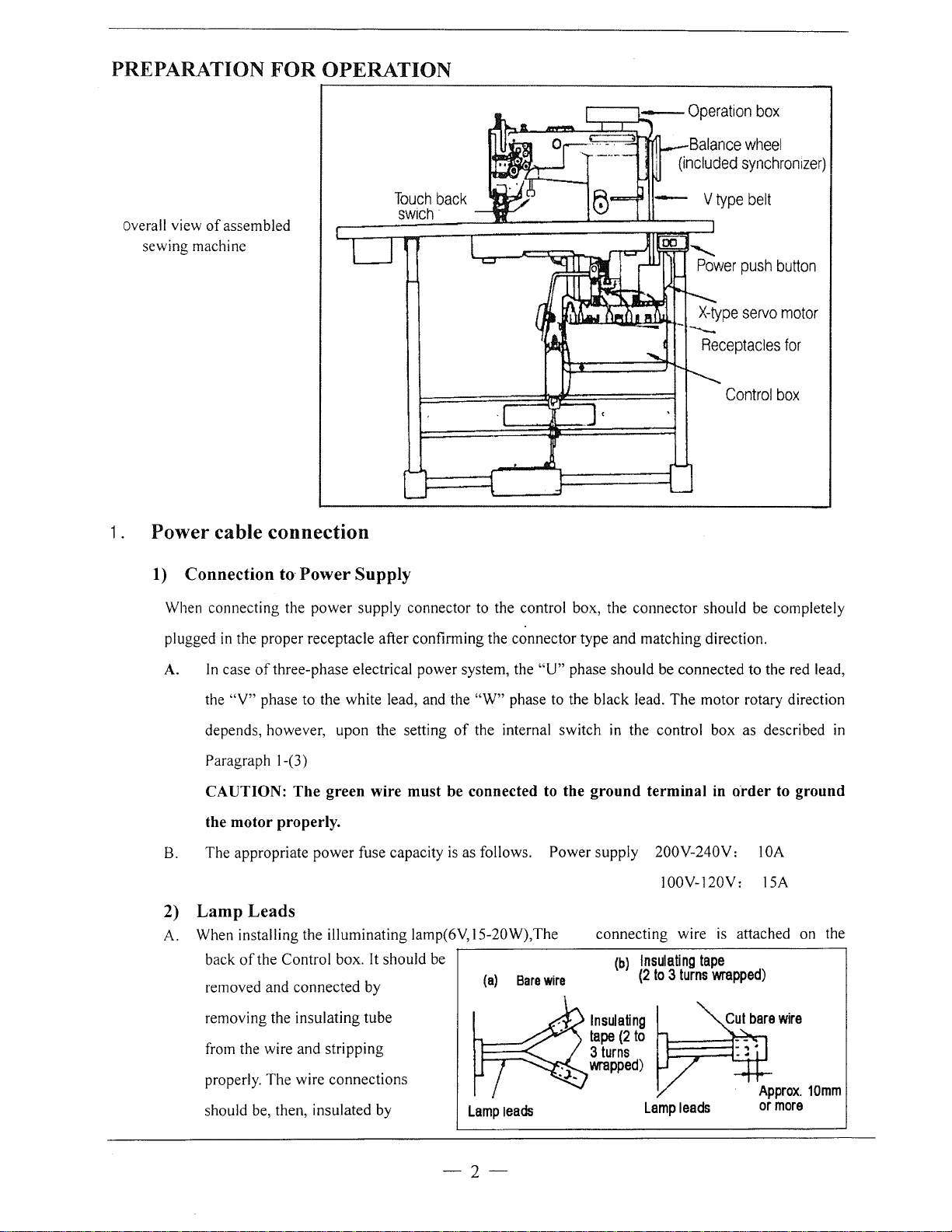
PREPARATION
FOR
OPERATION
Overall view
sewing machine
of
assembled
1 . Power cable connection
1)
Connection
to·
Power Supply
Touch
swich
back
Balance
(included
Control
wheel
synchron1zer)
box
When connecting the
plugged
A.
in
the proper receptacle after confirming the connector type and matching direction.
In
case
of
the
"V"
phase to the white lead, and the
depends, however, upon the setting
Paragraph 1-(3)
power
three-phase electrical power system, the
supply connector to the control box, the connector should be completely
"W"
phase to the black lead.
of
the internal switch
"U"
phase should be connected to the red lead,
The
in
the control box as described
CAUTION: The green wire must be connected to the ground terminal
the motor properly.
B.
The appropriate
power
fuse capacity
is
as follows.
Power
supply 200V-240V: I
IOOV-120Y: 15A
2) Lamp Leads
A. When installing the illuminating lamp(6V, 15-20W),The connecting wire
back
of
the Control box.
removed and connected by
removing the insulating tube
from the wire and stripping
properly. The wire connections
It
should be
~---------------------------------------.
(a)
Bare
wire
(b)
Insulating
(2
Insulating
tape
(2
to
3
turns
wrapped)
to 3 turns
motor rotary direction
in
in
order to ground
OA
is
attached on the
tape
wrapped)
should be, then, insulated by
Lamp
leads
--2--
Lamp
leads
wrapping insulating tape on the wires.
2.
CAUTION:
B.
When the illuminating lamp
shown
control box will be possibly burned out.
in
CAUTION:
3)
Rotary
It
is
possible to change the rotary direction
bottom left side
switch.
facing to the motor pulley, and
counterclockwise as facing to the motor pulley, matching with the
The
Connection
The control
as
shown to the right.
box
The
power switch must be
is
not used, the end
the figure
on
right side.
The
illuminating lamp must not be connected
warmer
It
and
may cause
If
a short circuit occurs failing to insulate, the transformer
others, in parallel. Otherwise, the
transformer
direction
of
the front
built-in lamp in the internal switch
of
control
should
be connected
box
cover
on the control box, and push
on
when rotating clockwise.
Operation
Turned
winding
of
is
box
-
~----
--
---\-
off before connecting the lamp.
of
the lamp leads
burned
the motor by
off
when the motor is rotating counterclockwise as
-
must
with
load
out.
removing
The
rotary
machine
Round
hole
in
table
be insulated as (a) or (b) as
any heater, such as a foot
capacity will be exceeded.
the rubber cap from the
the
internal direction selector
direction has been set to
prior to shipping
in
the
3.
Note:
(1)
(2)
Adjustment
1)
Adjust
When the pedal
machine stops at
deviate larger
a)
Disconnect the
the machine head.
Be
sure to
turn
the power switch
off for safety before connecting
or disconnecting the connectors.
The combination
heads with
panels
Use
are
special
of
the machine
the
motor
control
specified below.
care
for the
correct
combination when replacing the machine head
of
of"UP"
needle
position
is
kicked down by heel, the
"UP"
than
3 mm, adjust as follows.
plug
(12 pins)
bar
position.
of
stop
If
the marks
cable from
position
~-----------------------------------,
or
motor control panel.
b)
Run the
c) While holding the pulley, insert the
machine
and stop at
"UP''
position.
"adjusting
--3--
white mark
Black mark
"UP"
position
"DOWN" position
tool" in the hole" A", then remove the tool.
of
2) A.djust
When the pedal is
"Down"
at
than 5 mm, adjust as follows.
a) Disconnect the plug (12 pins)
the machine head
"Down"
position.
position
"Neutral" the machine stops
If
the marks deviate large
of
cable from
Adjusting
tool
AFTER
b) Run the machine and stop at
c) While holding the pulley, insert the "adjusting tool"
Confirm the stop operation, then set the plug (12 pings) coming from the machine head into the
3)
receptacle.
"Down"
CAUTIONS ON USE
1.
Oiling (1)
Fill the oil reservoir with oil up to
Oil level should be periodically checked.
is
2.
Oiling (2)
level
"H''
found below
level.
When a new sewing machine is used for
the first time,
of
use for considerably long time is used
again, replenish a suitable amount
"L"
level replenish oil to
For oil, Use white spindle
or
sewing machine left out
"H"
of
position.
mark.
If
oil
oill.
oil to
in
the hole
"8",
then remove the tool.
the portions indicated by arrow in the below
figure
3.
Oiling condition
See dripping
hole to check oiling condition during operation.
of
oil through the oil sight
-4-
4. Adjustment
5.
Cautions on
a)
When the power
foot away from the pedal.
b)
It
should be noted that the brake
of
oiling to
operation
is
turned on
rotating
or
off, keep
may
hook
Nut
not
work when the power is interrupted
failure occurs during
c) Since dust
in
the control
sewing
box
machine operation.
might cause
or
power
malfunction or control troubles, be sure to keep the control
d) Do not apply a multimeter to the control circuit for checking;
might damage semiconductor components
in
the circuit.
OPERATION
1 . Installation of needles
Note: Before installing the needles, be sure to
Double
tho
acrow
Needle
noodle
keeping
upto
tho
the
long
boHDm
grow
of
aida
noodle
of
clamp
noodle
face
and
tighton
to
face
Insufficient
insertion
Insert
tho
turn
off
the power.
box
cover
otherwise
Needle
distorted
close during operation.
voltage
of
multimeter
Single
Needle
X
2. Winding of bobbin
Note: When bobbin
Adjustment:
Tension
Conically wound thread
Length
of
wound thread
of
wound thread
thread
thread
is
wound, keep the presser foot lifted.
is
Slack winding
recommended for polyester thread
and nylon thread.
Move the thread guide toward smaller diameter
wound thread layer.
Loosen the thread length adjusting screw to increase length
-5-
X·
Long
left
of
groove
side
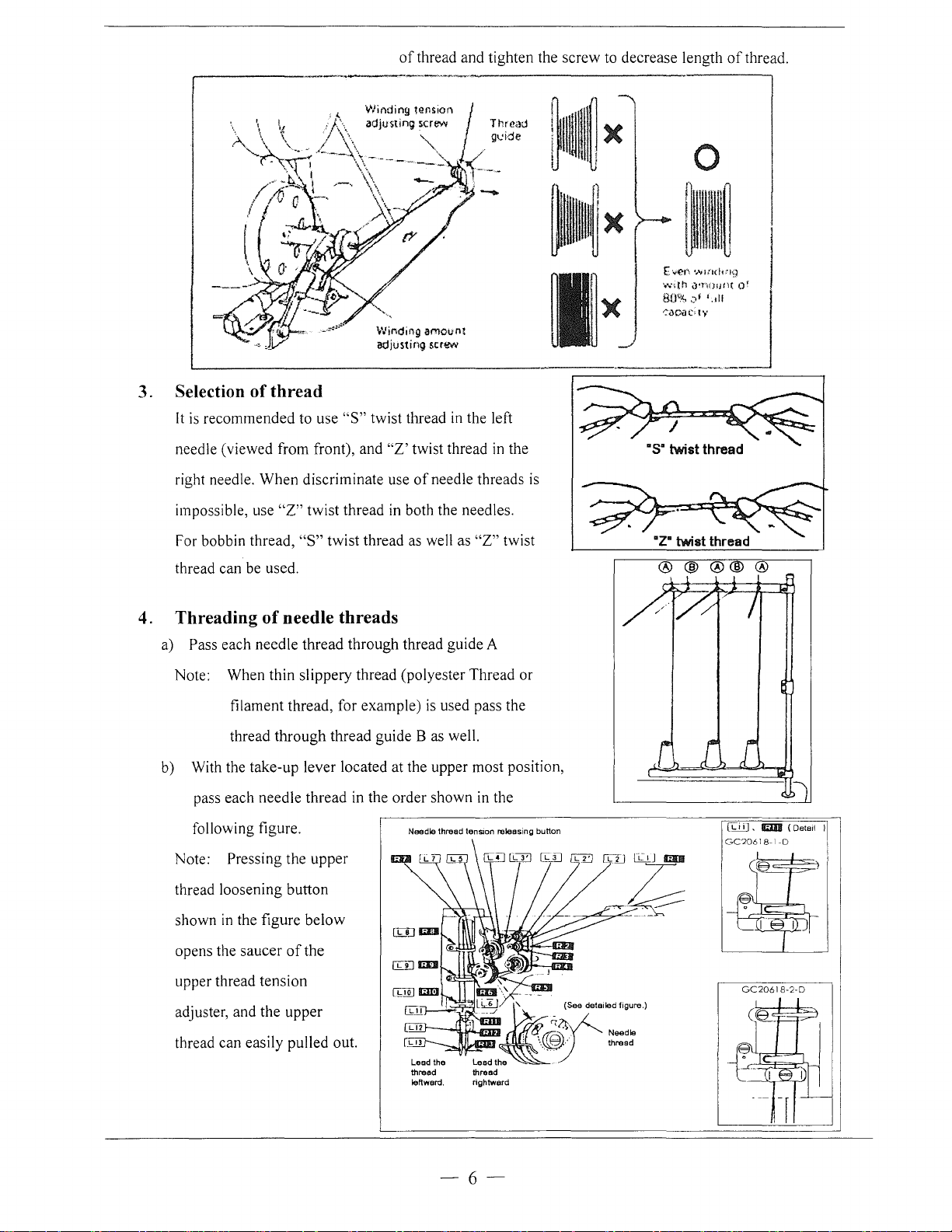
of
thread and tighten the screw to decrease length
--~-~---------------
X
Wir,ding amount
adjusting
scrtM>
of
-------.
0
E-.e-n
"""'("''9
..........
th
~·'n()!Jt\(
80'!<.
.)1
~<lC-<J(>!•,•
Qf
'.!II
thread.
3. Selection
It
is
recommended to use
needle (viewed from front), and
right needle. When discriminate use
impossible, use
For bobbin thread,
of
thread
"S"
twist thread
"Z'
twist thread
of
needle threads is
"Z"
twist thread in both the needles.
"S"
twist thread as well as
thread can be used.
4. Threading
of
needle threads
a) Pass each needle thread through thread guide A
Note: When thin slippery thread (polyester Thread
filament thread, for example)
is
used pass the
thread through thread guide B as well.
b)
With the take-up lever located at the upper most position,
in
pass each needle thread
following figure.
Note:
Pressing the upper
the order shown
Needle thread tenSion releasing button
in
the left
"Z"
in
in
twist
the
the
or
[i,J_iJ •
lfiDJI
GC2061 8-I
-D
(Detail
I
thread loosening button
in
shown
opens the saucer
the figure below
of
the
upper thread tension
adjuster, and the upper
thread can easily pulled out.
Lead the
thread
leftward.
thread
rightward
-6-
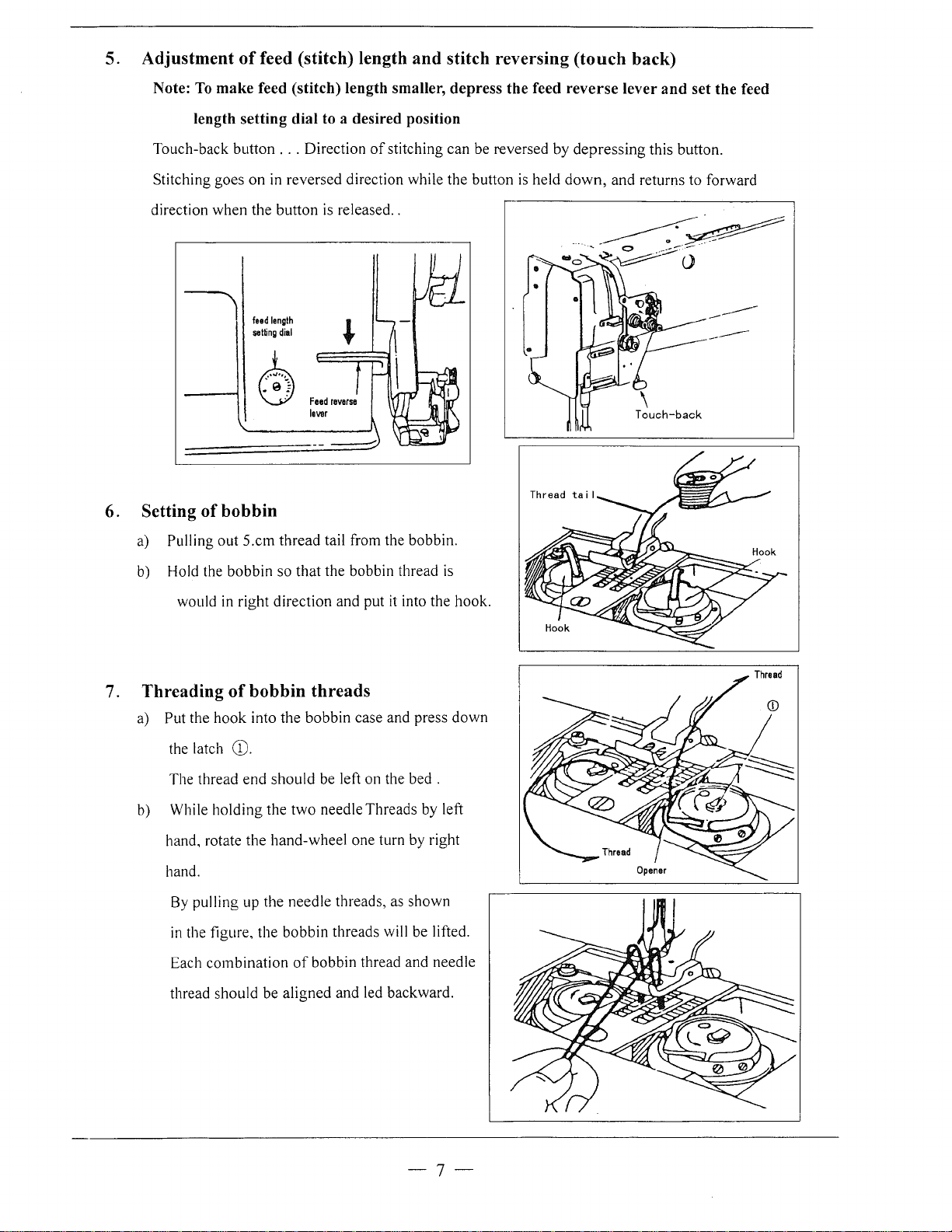
5. Adjustment
Note:
To
make feed (stitch) length smaller, depress the feed reverse lever and set the feed
length setting dial
of
feed (stitch) length and stitch reversing (touch back)
to
a desired position
Touch-back button
Stitching goes
direction when the button
6. Setting
a) Pulling
b)
of
out
Hold the bobbin so that the bobbin thread
...
Direction
on
in reversed direction while the button
feed
length
setting
dial
is
released
of
stitching can be reversed by
..
k
~
bobbin
S.cm thread tail from the bobbin.
depressing
is
held
down,
is
this button.
and returns to forward
would
7. Threading
a) Put the
b)
hand, rotate the hand-wheel one turn by right
hand.
hook
the latch
The thread
While holding the
By
pulling up the needle threads, as shown
in
the figure, the bobbin threads will be lifted.
combination
Each
thread should be
in
right direction and put it into the hook.
of
bobbin threads
into the bobbin case and press
CD.
end
should
be left on the bed .
two
needle Threads by left
of
bobbin thread and needle
aligned
and led backward.
down
-7-
8. Tension
of bobbin
adjustment
threads
9.
Balance
A 0
,2
BX
2:::~
1
of
thread
==~CJI
tension
Balance tension
1 1
nQht
needle
bobbin tension
il~
1;?
or
loose
Tension
adjusting
screw
10. Needle
• Needle thread tension should be adjusted in
•
• Needle thread tension can be also adjusted for
11. Adjustment
thread
reference to bobbin thread tension.
To
adjust needle thread tension, turn each tension
adjusting nut.
special fabric and thread by changing intensity and
movable range
Pressure to fabric(s) can be adjusted by turning the
pressure adjusting screw.
tension
of
slack thread adjusting spring.
of
presser
foot pressure
ex/~
~~~orognt
bobbin tension
12. Timing between rotating hook motion
needle motion
(1) Set feed length (stitch length) to
setting dial.
(2) When needle is lifted 2.4mm from the lower dead
point, as shown in Figure, the following positional
relationship should be maintained.
The upper edge
2.3mm below the hook point.
• The hook point should be located at the
center
of
• Gap between the hook point and the side face
of
needle should be
of
needle eye should be
needle axis.
O.O.Smm.
"6"
on the feed
-8-
and
Gap
between
hook
Needle
lift:
2.4mmfrom
needle
lower
dead
point
Center
of
needle
axis
point
and
upper
edge
of
needle
eye

II
Positioning
(1) When the needle is at
of
hook
point
DOWN
position, the smaller
Crossed heli.cal gears
should be engaged with the large wheel so that the
"S"
screw
of
of
and that
(2) Tighten each
set screw, on the
(3) Approximate position
should be found close to the needle when the
is
at
DOWN
finely adjust timing between the needle motion and
hook motion, loosen the set screw
wheel and move the gear wheel in its axial direction
within a range from 1 mm to 2mm.
the latter
13. Adjustment
Height
of
feed
on
the right side and left side
the former gear
gear
"S"
screw, where is punched for
hook
of
position.
of
feed dog height
dog
and pressure
comes
on
the reverse side.
shaft.
hook
"C"
of
of
on the front side,
screw
of
hook
needle
larger gear
presser foot should
Noedlo
position
1-2mm
c,
~
j
DOWN
1-2mm
~
be adjusted for individual fabric(s) with the following
cautions:
if
Fabric will be damaged
or pressure
Even stitch length cannot be assured
too low or pressure
Feed dog height should be measured at the point where
the needle is at the top position.
For light fabrics
For usual fabrics
For heavy fabrics
of
presser foot
the feed dog extends too high,
is
too large.
if
the feed dog
of
presser foot
Approx. O.Smm from throat plate
Approx.
Approx. 1.2mm from throat plate
is
toe small.
l.Omm from throat plate
Adjustment procedure
a) Lean the machine head backward.
Tum
b)
the hand wheel by hand and stop
dog rises to the maximum height.
wh<::n
lmm
1.2mm
is
the feed
c) Loosen the feed bar set screw.
d) Vertically move the feed bar (in the direction indicated by arrow in the figure) to adjust
adequate height.
-9-
it
to
e) After the adjustment, tighten the feed bar set screw.
is
• The feed dog height
factory-adjusted to 1.2mm
14. Relationship between
and
motion
When the timing belt (toothed belt) was removed for
its replacement, for example, the relationship between
rotating hook motion and take-up lever motion should
be adjusted
a)
Tum the balance wheel and stop when the take-up
lever
b)
Lean the machine head backward and make sure the arrow (timing mark) put on the timing belt
lipe with the black line on the boss
c)
If
the timing mark
adjust.
take-up
as
follows:
is
lifted to its upper dead point.
rotating
hook
lever motion
of
is
not in line with the black line ,remove the timing belt and install it again to
15. Relationship between hook motion
and
opener
a)
Tum the balance wheel by hand and stop when
the opener holder
motion
is
located most remotely from
lower shaft bearing.
Approx.
Black
lower
line
on
shaft
0.2mm
boss
bearing
of
Timing
belt
sprocket
is
in
the throat plate.
b)
Make sure gap between the bobbin case holder A
and the opener
c)
If
the gap
holder set screw
16. Relationship between needle motion
a)
Set feed length to
b) Lean the machine head backward.
c) Loosen the feed lifting rock shaft crank set screws A and B
d) Set the needle at the lowest position.
e) Adjust the distance between presser rod and vibration
prevention rod to 9mm and temporarily tighten the feed
lifting rock shaft crank set screws A and B
t)
Check that the right feed lifting rock shaft crank
connected with the link at right angle,
is
approximately 0.2mm.
is
too large or
Band
"0"
small,
adjust position
on the feed setting dial
loosen the opener
of
the opener.
as
shown in Figure.
and
feed dog motion
is
A
Opener
Screw
.-----------------------------.
Link
If
the connection
g)
cover, loosen screw C and move the right link to connect
the right feed lifting rock shaft with the link at right angle.
is
not at right angle, remove the back
-10-
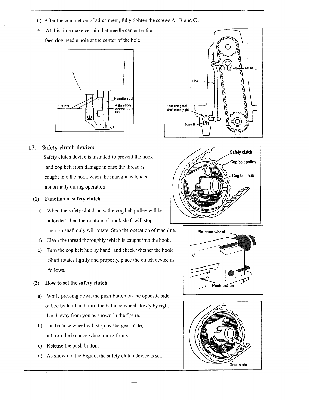
h)
After the completion
• At this time make certain that needle can enter the
of
adjustment, fully tighten the screws A , B and
C.
feed dog needle hole at the center
~;:r--'
9mm
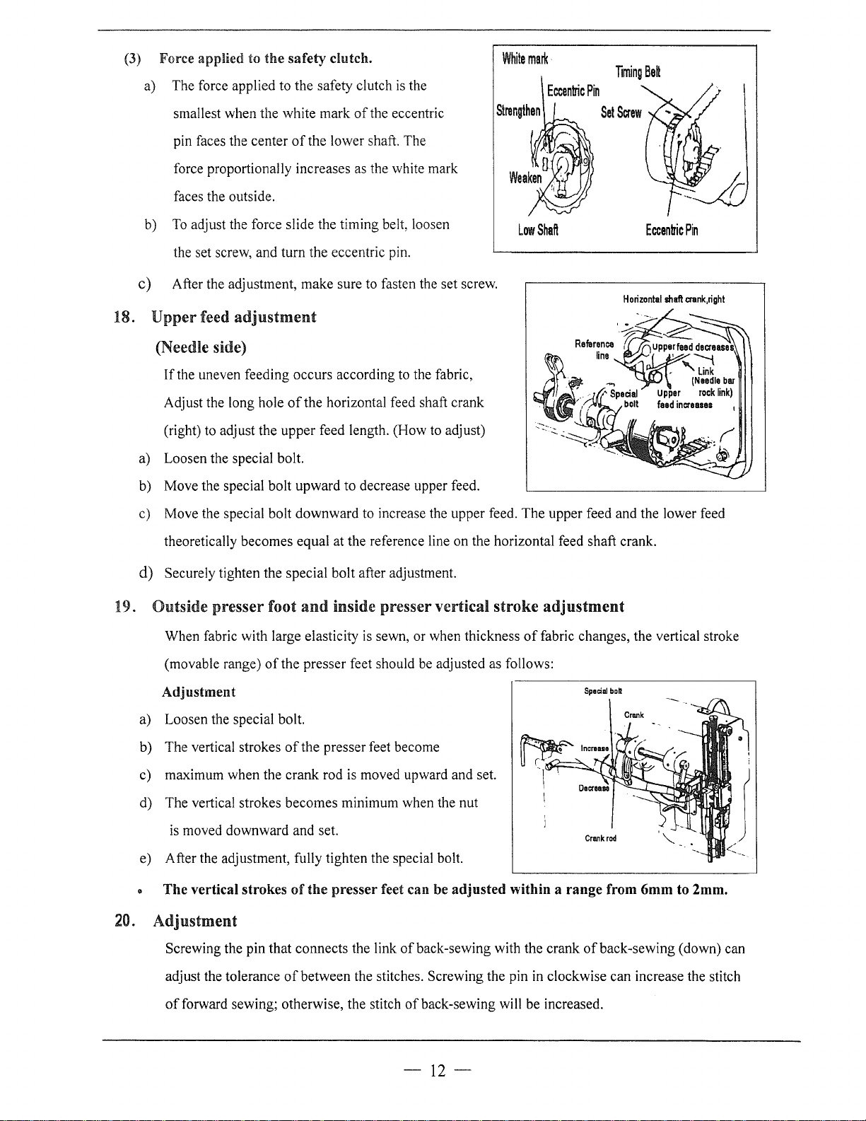
17. Safety clutch device:
Safety clutch device
and cog belt from damage in case the thread
caught into the hook when the machine
is
of
the hole.
I
I
Needle
rod
Vibration
prevention
rod
installed to prevent the hook
is
is
loaded
Feed
shaft
lifting
crank
rock
(rlght)
Safety
Cog
belt
Cog
clutch
pulley
belt
hub
abnormally during operation.
(1)
Function of safety clutch.
a)
When the safety clutch acts, the cog belt pulley will
unloaded. then the rotation
The arm shaft only will rotate. Stop the operation
b)
Clean the thread thoroughly which
c)
Turn the cog belt hub by hand, and check whether the hook
Shaft rotates lightly and properly, place the clutch device as
follows.
(2)
How to set the safety clutch.
a)
While pressing down the push button on the opposite side
of
bed by left hand, turn the balance wheel slowly by right
hand away from you as shown
b)
The balance wheel will stop by the gear plate,
of
hook shaft will stop.
is
caught into the hook.
in
the figure.
be
of
machine.
~·
.....__
_.->' · · Push button
but turn the balance wheel more firmly.
c)
Release the push button.
d)
As shown
in
the Figure, the safety clutch device
-
11-
is
set.
(3)
Force applied to the safety clutch.
a) The force applied to the safety clutch
smallest when the white mark
is
of
the eccentric
the
White
marl<
Eccentric
Strengthen
Pin
Timing
Be~
pin faces the center
force proportionally increases as the white mark
faces the outside.
b)
To
adjust the force slide the timing belt, loosen
the set screw, and turn the eccentric pin.
of
the lower shaft. The
Low
Shaft
Eccentric
c) After the adjustment, make sure to fasten the set screw.
Horizontal
shaft
18. Upper feed
adjustment
(Needle side)
If
the uneven feeding occurs according to the fabric,
Adjust the long hole
(right) to adjust the upper feed length. (How to adjust)
a) Loosen the special bolt.
b) Move the special bolt upward to decrease upper feed.
c) Move the special bolt downward to increase the upper feed. The upper feed and the lower feed
theoretically becomes equal at the reference line on the horizontal feed shaft crank.
of
the horizontal feed shaft crank
Pin
crank,righl
d) Securely tighten the special bolt after adjustment.
19. Outside presser foot
When fabric with large elasticity
(movable range)
Adjustment
a) Loosen the special bolt.
b) The vertical strokes
c) maximum when the crank rod
d) The vertical strokes becomes minimum when the nut
is
moved downward and set.
e) After the adjustment, fully tighten the special bolt.
The vertical strokes
20.
Adjustment
Screwing the pin that connects the link
adjust the tolerance
and
inside presser vertical stroke
is
sewn, or when thickness
of
the presser feet should
of
the presser feet become
is
moved upward and set.
of
the presser feet can be adjusted within a range from 6mm to 2mm.
of
between the stitches. Screwing the pin
be
of
back-sewing with the crank
adjustment
of
fabric changes, the vertical stroke
adjusted as follows:
~Increase
~
r~
in
Spacial
bo~
Crank
rod
of
back-sewing (down) can
clockwise can increase the stitch
of
forward sewing; otherwise, the stitch ofback-sewing will be increased.
-12-
21. Installation
(1)
Installation
a.
Turn the balance wheel and lower the needle bar to the lowest position.
b.
Push the cam follower crank so that the cam roller enters into the thread trimmer cam groove.
c.
Turn the balance wheel until the black mark point on the arm meets the white mark point on the
balance wheel. Set the cam follower crank at this position with a screwdriver temporarily preventing
the cam roller coming out from the cam groove.
d.
Loosen the thread trimmer rocking crank clamp bolts A and B.
e.
Adjust the movable knife so that the movable knife end slant portion protrudes
0-0.5
mm
from the fixed knife, as shown
of
movable knife
of
movable knife
Bo~
A
Thread trimmer
rocking crank
in
Figure and tighten the bolts A and
B.
Thread trimmer
rockmg
crank
(2)
Gap
between movable knife
Turn the balance wheel by hand until needle reaches the
a.
and
bobbin case holder
stopper
.-------------,
Monable
knife
Lowest position.
b. With the needle at the lowest position, depress cam
follower
crank, turn the balance wheel until the movable knife reaches
of
the extremity
its stroke.
c. Manually rotate the inner hook in the direction indicated by
arrow
in
Figure and adjust gap between the movable knife
and the inner hook stopper to about 0.5 mm (the screws A and B should be loosened for this
adjustment).
22.
Adjustment
of
thread
trimmer
cam
a. Turn the balance wheel by hand until the needles reach the lowest position.
b. Maintaining the needle position, depress the cam follower crank and put the cam roller into the
groove
of
thread trimmer cam.
c. Turning the balance wheel by hand, adjust the thread trimmer cam so that the movable knife starts
moving when the green mark point on the balance wheel comes
-
13
in
line with the black mark point on
 Loading...