

Page 1
Customer
Copy
HIGHLEAD
GC20528 series
Service
Twin-Needle High Speed Split Needle
Sewing Machine
Instruction Manual
Parts
Catalog
Bar
Lockstitch
SHANGHAI HUIGONG
N0.3
SEWING MACHINE FACTORY
Page 2
CONTENTS
PRECAUTIONS
PREPARATION
1.
Power
cable connection
2.
Connection
3.
Adjustment
CAUTIONS
1.
Oiling
(I)
2.
Oiling (2) -------------------------------4
3.
Oiling condition --------------------4
4.
Adjustment
5.
Cautions
BEFORE
FOR
of
control
of
needle
ON
USE
of
oiling
on operation
STARTING
OPERATION
-------------------------------------- 1
OPERATION
----------------------------------------------2
box
----------------------------------------3
bar
stop
1 -
to
rotating
position
hook
--------------------------------------3
---------------------------------------4
--------------------------------------
-------------------------------------5
OPERATION
1.
Installation
2.
Winding
3.
Selection·ofthread --6
4.
Threading
5.
Adjustment
6.
Setting
7.
Adjusting
8.
Threading
9.
Tension
10.
Balance
11.
Needle
12.
Adjustment
13.
Timing
14.
Adjustment
15.
Relationship
16.
Relationship
17.
Relationship
18.
Installation
19.
Adjustment
20.
Adjustment
21.
Sharpening
of
needles---------
of
bobbin
of
needle
offeed (stitch)
of
bobbin
of
needle
of
bobbin
adjustment
of
thread
thread
tension
of
presser
between
rotating
of
feed
between
between
between
of
movable
of
thread
of
meshing
of
fixed
------------------------------------------
thread ----------------------------------6
threads ------------6
length
and
stitch
reversing
-----------------------------7
thread
guide
threads
of
bobbin
tension
dog
--....-------------
-----------------
foot
p~essure
hook
height-------------------'---------------------------rotating
hook.motion
needle
knife-----------------------------------------------
trimmer
pressure
knife
__________
----------------------------------------7
------threads
motion
hook
motion
cam
and
needle
motion
and
of
movable
and
opener
and
---------------------------
feed
motion
dog
knife
(touch-back) --------------------------- 7
------------------8
---------------8
---------------·---------------------8
----8
-------------------9
motion----------------------------------------9
take-up
lever
motion
----------------------
motion
and
------------
fixed
knife
_,______
------------------------
--------------
--- 1 1
------
5
5
10
10
11
12
13
14
14
22.
Adjustment
23.
Wiper
for
change
adjustment --------------
of
needle
gage-----------------
SPECIFICATIONS
PARTS
1.
2.
3.
CATALOG
Arm
bed
its
Thread
Arm
tension regulator
shaft & presser
accessories----------·-------
mechanism-------------------------------·
foot
mechanism
-------
----------
15
16
17
18
20
23
Page 3

4.
Needle bar rocking motion mechanism
5.
Stitch regulator mechanism
-------------------------------------------------------
-------------------------------------------------------------------
26
28
6. Lower shaft & feed rock shaft mechanism
7.
Hook saddle mechanism
8.
Knife
mechanism(
9. Knife mechanism ( = )
I 0. Touch back mechanism & detector mechanism
11.
Wiper mechanism
12.
Oil lubrication mechanism
13.
Accessories
GAUGE
PARTS
------------------------------------------------------------------------------------
LIAT
-----------------------------------------------------------------------
- )
-·---
-----------------------------------------------------------------------
-------------------------------------------------
--------------------------------------------------------------------
-----------------------------------------------------------
-------------------------------------------------------------------------
----------------------------------------------------
--------------------:--------------------------
·--------------------------
30
33
36
3 8
41
43
45
48
51
Page 4

PRECAUTIONS BEFORES STARING OPERATION
1.
Safety precautions
I) When turning the power on, keep your hands and fingers away from the area around/under
the needle and the area around the pulley.
off
2) Power must be turned
3) The power must be turned
belt, adjusting the machine, or when replacing.
4) Avoid placing fingers, hairs, bars etc. near the pulley,
when the machine is operation. Injury could result.
5) Do not insert fingers into the thread take-up cover, under/round the needle, or pulley when
the machine is in operation.
If
a belt cover, finger guard, and/or eye guard are installed, do not operate the machine without
6)
these safety devices.
2.
Precaution before Starting Operation
when the machine
off
before tilting the machine head, installing or removing the
is
not used, or when the operator leaves his/her seat.
"V"
belt, bobbin winder pulley, or motor
"V"
I) If the machine's oil pan has an oil sump, never operate the machine before filling
2)
If
the machine is lubricated by a drop oiler, never operate the machine before lubricating.
is
3) When a new sewing machine
power on. (the pulley should rotate counterclockwise when viewed from the pulley.)
4)
Verify
the voltage and (single or three) phase with these given on the motor nameplate.
first turned on, verify the rotational direction
it.
of
the pulley with the
3. Precaution for Operating Conditions
I) Avoid using the machine at abnormally high temperature (35°C or higher) or low temperature (S°Cor
lower). Otherwise, machine failure may result.
in
2) Avoid using the machine
Avoid using the machine
welder and others,
is
dusty conditions.
in
areas where too much electrical noise, resulted from the high-frequency
generated.
-1-
Page 5
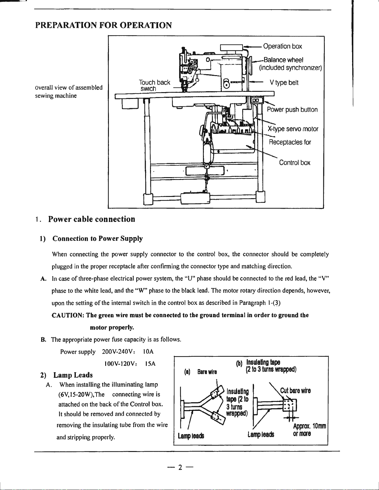
PREPARATION
FOR
OPERATION
overall view
sewing machine
of
assembled
1. Power cable connection
1)
Connection
to
Power Supply
!:-.:--::~:?n.Jr'P,._-Balance
(included
1------r----1:.-:...-:...-:...-_-_-_-
_-
_-
_---r_,
wheel
synchronizer)
Control
box
When connecting the power supply connector to the control box, the connector should be completely
plugged
A.
In
phase to the white lead, and the
upon the setting
CAUTION: The green wire must be connected
B.
The appropriate power fuse capacity
2) Lamp Leads
A. When installing the illuminating lamp
in
the proper receptacle after confinning the connector type and matching direction.
case
of
three-phase electrical power system, the
"W"
phase to the black lead. The motor rotary direction depends, however,
of
the internal switch in the control box as described
motor properly.
is
as follows.
Power supply 200V-240V: I 0A
I00V-120V: ISA
(6V,15-20W),The connecting wire is
attached
It
removing the insulating tube from the wire
and stripping properly.
on
the back
should be removed and connected by
of
the Control box.
"U"
phase should be connected to the red lead, the "V"
to
the ground terminal
(a)
Bare
wire
Lampteads
in
Paragraph
in
order
(b)
Insulating
(2
to 3 turns
lnsldattng
tape
(2
to
3
turns
wrapped)
Lamp
1-P)
to
tape
wrapped)
leads
ground the
- 2 -
Page 6
The
wire
connections should
be,
then, insulated
by
wrapping insulating tape
on
the wires.
CAUTION: The power switch must be Turned
B.
When
the
illumin.ating
shown
control
CAUTION: The illuminating lamp must not be connected with any heater, such as a foot warmer
in
box
the
will
3) Rotary direction
It
is
possible
left
side
of
the
built-in
motor
facing
lamp
pulley,
to
the
motor pulley, matching
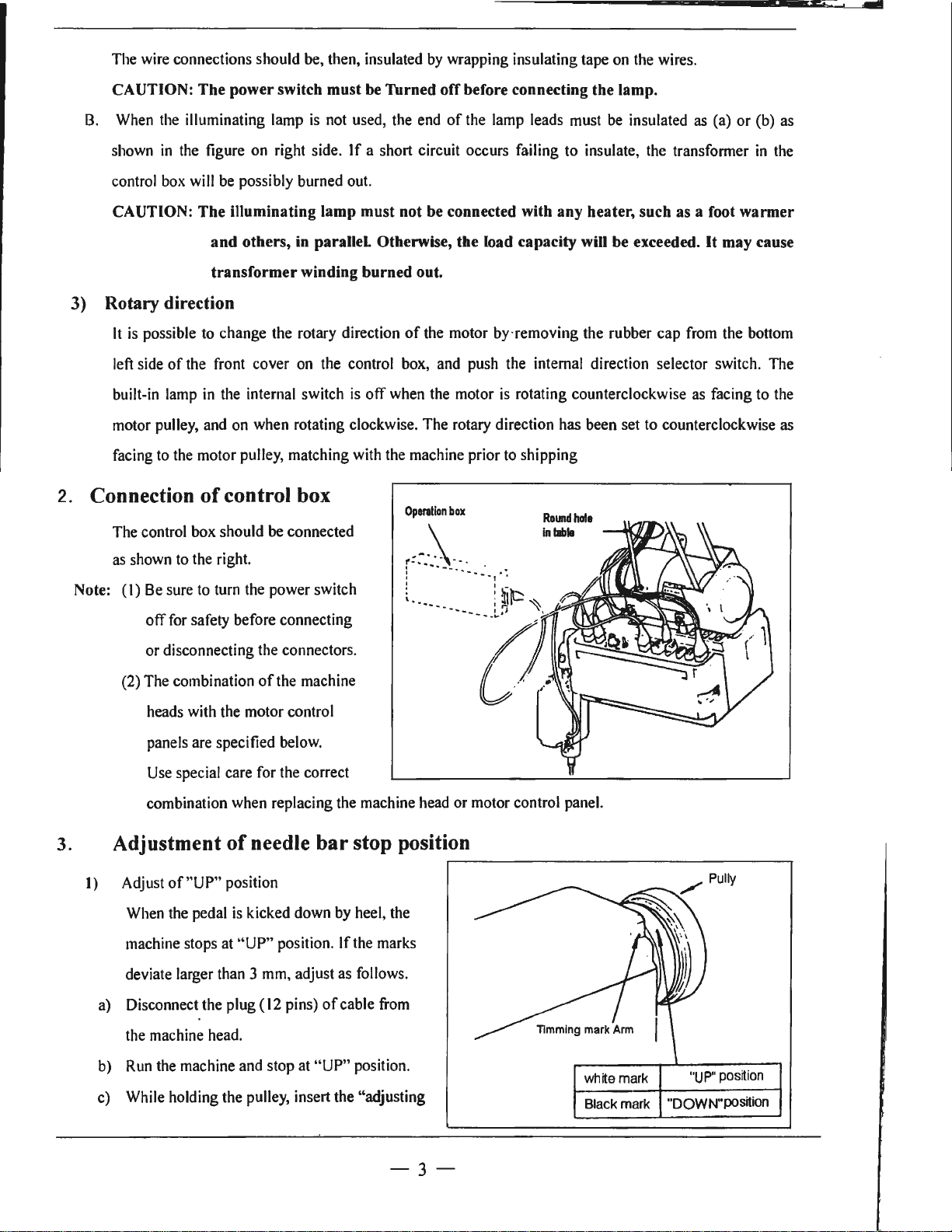
2. Connection
The control box should
lamp
is
not
used,
the
figure
on
right side. If a short circuit occurs failing
be
possibly burned
and others,
transformer winding burned out.
to
change the rotary direction
front cover
in
the
internal switch
and
on
of
control box
in
on
when
rotating clockwise. The
be
connected
out.
parallel. Otherwise, the load capacity will be exceeded. It may cause
of
the
control
is
with
off
when
the
box,
machine prior
off
before connecting the lamp.
end
of
the
lamp
leads
must
be
insulated
to
insulate,
the
the motor by· removing the rubber cap
and
push
the
internal direction selector switch.
the
motor
is
rotating counterclockwise
rotary
direction
to
has
shipping
Roundhola
In
labla
been set
to
as
(a) or
(b)
transformer
from
as
the
facing
in
bottom
to
counterclockwise
as
the
The
the
as
3.
as
shown
Note:
(I)
(2)
Adjustment
1)
Adjust of"UP" position
When
machine stops
deviate larger
a)
Disconnect the plug (
to
the
right.
Be
sure
to
turn
for
safety before connecting
off
or disconnecting
The
combination
heads
with
the
panels
are
specified
Use
special care
combination
when
of
the
pedal
is
at
"UP" position. If
than 3 mm,
the
power switch
the
connectors.
of
the
machine
motor control
below.
for
the
correct
replacing
the
machine
head
needle bar stop position
kicked down
12
pins)
adjust
of
by
heel,
the
as
follows.
cable
the
marks
from
or motor control panel.
the
b)
c)
machine
Run
While
the
head.
machine
holding the
and
pulley,
stop
at
"UP" position.
insert the "adjusting
-3-
wh
lte
mark
Black mark
"UP"
position
"DOWN"position
Page 7

tool" in the hole" A", then remove the tool.
2) Adjust
When the pedal is "Neutral" the machine stops at
5 mm, adjust
a) Disconnect the plug ( 12 pins)
the machine head
b) Run the machine and stop at
c) While holding the pulley, insert the "adjusting
3)
Confirm the stop operation, then set the plug (
pings) coming from the machine head into the
of
"Down"
tool"
in
the hole "B", then remove the tool.
receptacle.
as
follows.
position
of
"Down"
CAUTIONS ON USE
1.
Oiling (1)
Fill the oil reservoir with oil up to
Oil level should be periodically checked.
"L"
level is fottnd below
level replenish oil to
cable from
position.
"H"
mark.
If
oil
12
"Down
@
" position.
If
the marks deviate large than
"H"
level .
For oil, Use white spindle
2. Oiling (2)
When a new sewing machine is used for the first time,
considerably long time is used again, replenish a suitable amount
arrow
in
the below figure
oill.
--~~:.~
....
····
c-..
~ ·
·~
or
sewing machine left
of
oil to the portions indicated by
out
of
use for
3. Oiling condition
(I)
See
dripping
of
oil during operation through the oil sight window to check oiling condition in the
- 4 -
Quantit y of
oll
:2 - 3
drop•
Page 8
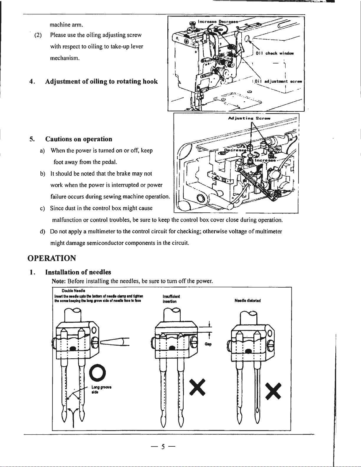
(2)
machine
Please
with
mechanism.
arm.
use
respect
the oiling adjusting screw
to
oiling
to
take-up lever
Adjustment
4.
Cautions on operation
5.
a)
When
the
power
foot
away
b)
It
should
work
failure
c)
Since dust
malfunction or control troubles,
d)
Do
might
be
when
occurs during sewing machine operation.
in
not
apply a multimeter
damage semiconductor components
of
oiling to rotating hook
is
turned
on
or
off,
from
the
pedal.
noted
that the brake
the power
the
is
interrupted or power
control box might cause
may
be
to
the control circuit
keep
not
sure
to
keep
in
the
the
control box cover close during operation.
for
checking; otherwise voltage
circuit.
of
multimeter
OPERATION
l.
Installation
Note: Before installing
Double
lnalll
th1
1111d1
Iha
ICIIW
kNping
of
Needle
uplo
Iha
needles
the
bollllm
of
··"
nNdl
aide
lo,w
0
LOl'IDIJl'DCIH
Iida
the
of
n11dll
needles,
clamp
1ml
l'IH
tli,iten
lo
l'ICI
be
sure
to
turn off
lnlllfficienl
Inmon
the
power.
X
Needle
dillorled
X
-5-
Page 9
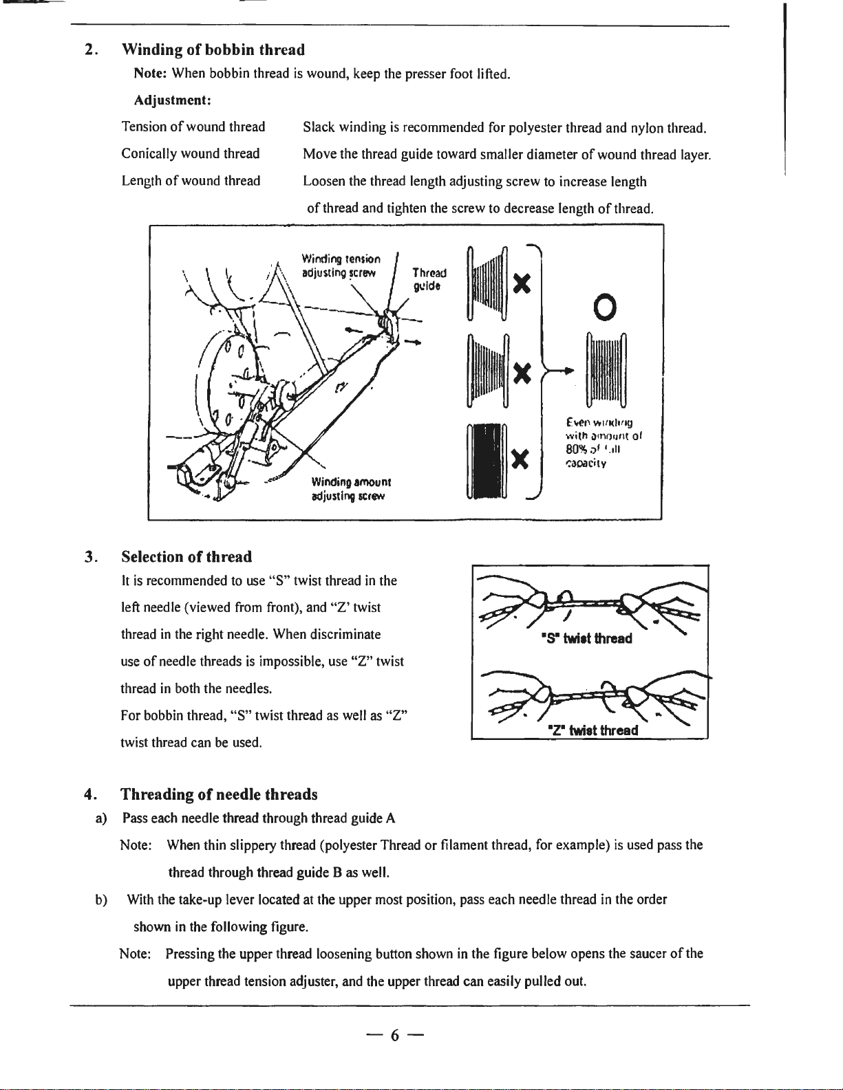
2. Winding
of
bobbin thread
Note: When bobbin thread
Adjustment:
Tension
Conically wound thread
Length
of
wound thread
of
wound thread
is
wound, keep the presser foot lifted.
Slack winding
Move the thread guide toward smaller diameter
Loosen the thread length adjusting screw to increase length
of
thread and tighten the screw to decrease length
Winding
adjustlnv
amount
screw
is
recommended for polyester thread and nylon thread.
of
wound thread layer.
of
thread .
;;~
~~
~
)(
!~
x
f.
It(?!\
Vt
with il
tn<
80%
:,I •.
-:aoacitv
lfl<llf
>•mt
1II
~x
l!J
of
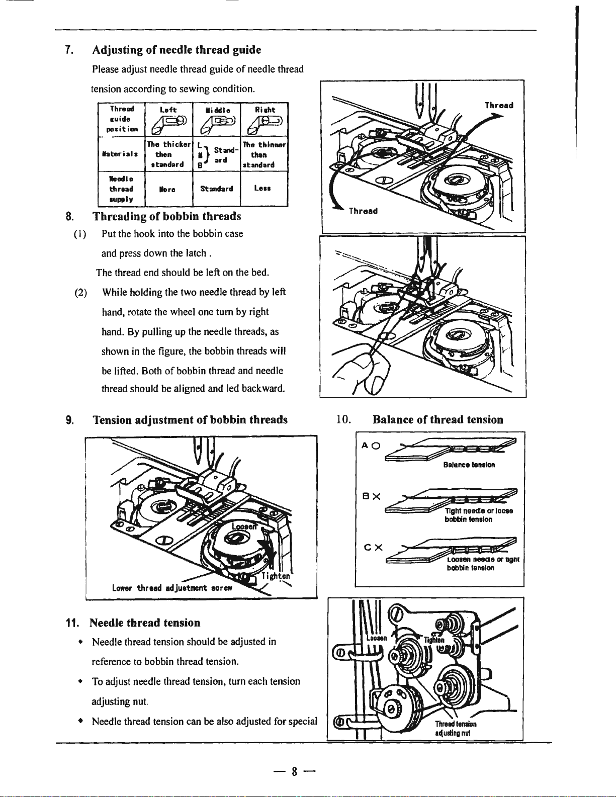
3. Selection
It
is
left needle (viewed from front), and
thread
use
of
thread
For bobbin thread,
twist thread can be used.
4. Threading
a) Pass each needle thread through thread guide A
Note: When thin slippery thread (polyester Thread
b) With the take-up lever located at the upper most position, pass each needle thread
shown
Note: Pressing the upper thread loosening button shown
of
thread
recommended to use
in
the right needle. When discriminate
needle threads
in
both the needles.
of
needle threads
thread through thread guide B as well.
in
the following figure.
"S"
twist thread
is
impossible, use
"S"
twist thread as well as
"Z'
in
twist
"Z"
the
twist
"Z"
or
filament thread, for example)
in
the figure below opens the saucer
is
used pass the
in
the order
of
the
upper thread tension adjuster, and the upper thread can easily pulled out.
-6-
Page 10

@@
@@@
Needle
thread tension releasing button
IL9)
I
···-.
......
..
_
5. Adjustment
Note:
To
make
setting
Touch-back button
Stitching goes
direction
when
f11dlongth
Mtting
k
~
-----·- ·-·-
of
feed (stitch) length and stitch reversing (touch back)
feed
(stitch) length smaller, depress
dial
to
a desired position
..
. Direction
on
in
reversed direction while
the
button
dial
is
released.
of
stitching
-----~------------~
the
feed
reverse lever and set the
can
be
the
reversed
button
by
depressing this button.
is
held
down, and returns
I
I
"\
feed
to
forward
------------·
_ .----
length
6. Setting
leading
(I)
Pulling out thread
bobbin case.
(2)
Threading following ( I
(3)
Put
hook
(4)
Press
(5)
Leading
of
the
the
bobbin case
shaft.
the
bobbin bar.
the
bobbin
lower thread
lower thread over
and
from
side
)-(5)
to
rotating hook, then replace
install
A,
then
bed
the
install
plate .
bobbin
the
-7-
Page 11
7.
Adjusting
of
needle thread guide
Please adjust needle thread guide
tension according to sewing condition.
8.
(I)
(2)
Thread
1uide
posit
ion
~-
hteriah
•edte
thread
supply
Threading
Put the hook into the bobbin case
and press down the latch .
The thread end should be left on the bed.
While holding the two needle thread by left
hand, rotate the wheel one
hand. By pulling up the needle threads, as
shown
Left
r)
The
thicker
then
standard
lore
of
bobbin threads
in
the figure, the bobbin threads will
~}
8
M
iddle
~)
Standard
Standard
tum
of
needle thread
Ri1ht
~)
The
thinner
than
atandard
Lesa
by right
be lifted. Both
thread should be aligned and led backward.
Tension adjustment
9.
11.
Needle thread tension
• Needle thread tension should be adjusted
reference to bobbin thread tension.
of
bobbin thread and needle
of
bobbin threads
in
10.
AO
BX~
cx.2~r
Balance
of
thread tension
r2:::,
'
::hi
12>
Balance
I
neade
bobbin
bobbin
tension
I~
or
lenelon
tension
~
loose
•
To
adjust needle thread tension, tum each tension
adjusting nut.
• Needle thread tension can be also adjusted for special
-8-
Page 12
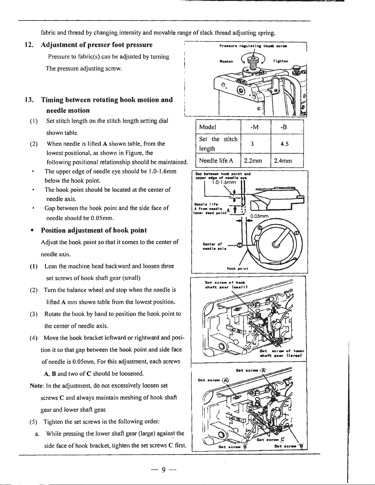
fabric and thread by changing intensity and movable range
12.
Adjustment
of
presser foot pressure
Pressure to fabric(s) can be adjusted by turning
The pressure adjusting screw.
13.
Timing between rotating hook motion and
needle motion
(I)
Set stitch length on the stitch length setting dial
shown table .
(2) When needle
lowest positional, as shown
following positional relationship should be maintained.
The upper edge
below the hook point.
The hook point should be located at the center
needle axis.
Gap between the hook point and the side face
needle should be 0.05mm.
is
lifted A shown table, from the
in
Figure, the
of
needle eye should be 1.0-I .6mm
of
of
of
slack thread adjusting spring.
Preeaure
Model -M
Set the
length
Needle life A
Oap
betwHn
hook po i
eds•
upper
of
stitch
nalld
reau I at
Inc
thunib
3 4.5
2.2mm 2.4mm
nt
and
I•
•Y•
•crew
-B
LJ~m'-11+--c:;5:::;c:=:==~
,-
Neadlo I lfe:
• Position adjustment
Adjust the hook point so that it comes to the center
of
hook point
of
needle axis.
(I)
Lean the machine head backward and loosen three
of
set screws
(2) Turn the balance wheel and stop when the needle
lifted A
hook shaft gear (small)
mm
shown table from the lowest position.
is
(3) Rotate the hook by hand to position the hook point to
of
the center
(4) Move the hook bracket leftward
needle axis.
or
rightward and posi-
tion it so that gap between the hook point and side face
of
needle is 0.05mm. For this adjustment, each screws
A, B and two
Note:
In
screws
the adjustment, do not excessively loosen set
C and always maintain meshing
of
C should be loosened.
of
hook shaft
Oenter
neadl•
Set:
of
axla
screw
of
hook
gear and lower shaft gear.
in
(5) Tighten the set screws
the following order:
a. While pressing the lower shaft gear (large) agains_t the
of
side face
hook bracket, tighten the set screws C first.
- 9
--
Set:
aor-
Set:
.
¢'
\
•c~
...-
e·
Page 13
b.
After checking gap between the needle and the hook,
c.
Then tighten the set screws
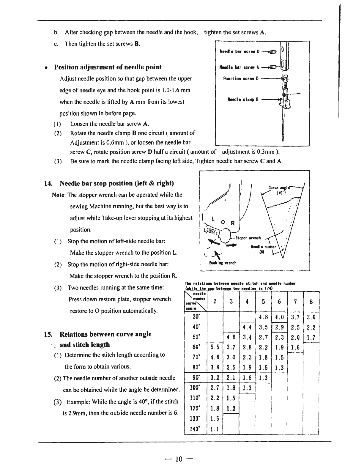
• Position adjustment
Adjust needle position so that gap between the upper
of
edge
when the needle
needle eye and the hook point
is
of
lifted
B.
needle point
by A mm
from its lowest
is
1.0-1.6
mm
tighten the set screws
•
...
,.
'"
"'· 0 --
Needle
bar
acrew
A.
A__......~
~!
11
--
position shown
(I)
Loosen the needle bar screw A.
(2) Rotate the needle clamp B one circuit ( amount
Adjustment is 0.6mm ), or loosen the needle bar
screw C, rotate position screw D half a circuit ( amount
Be
(3)
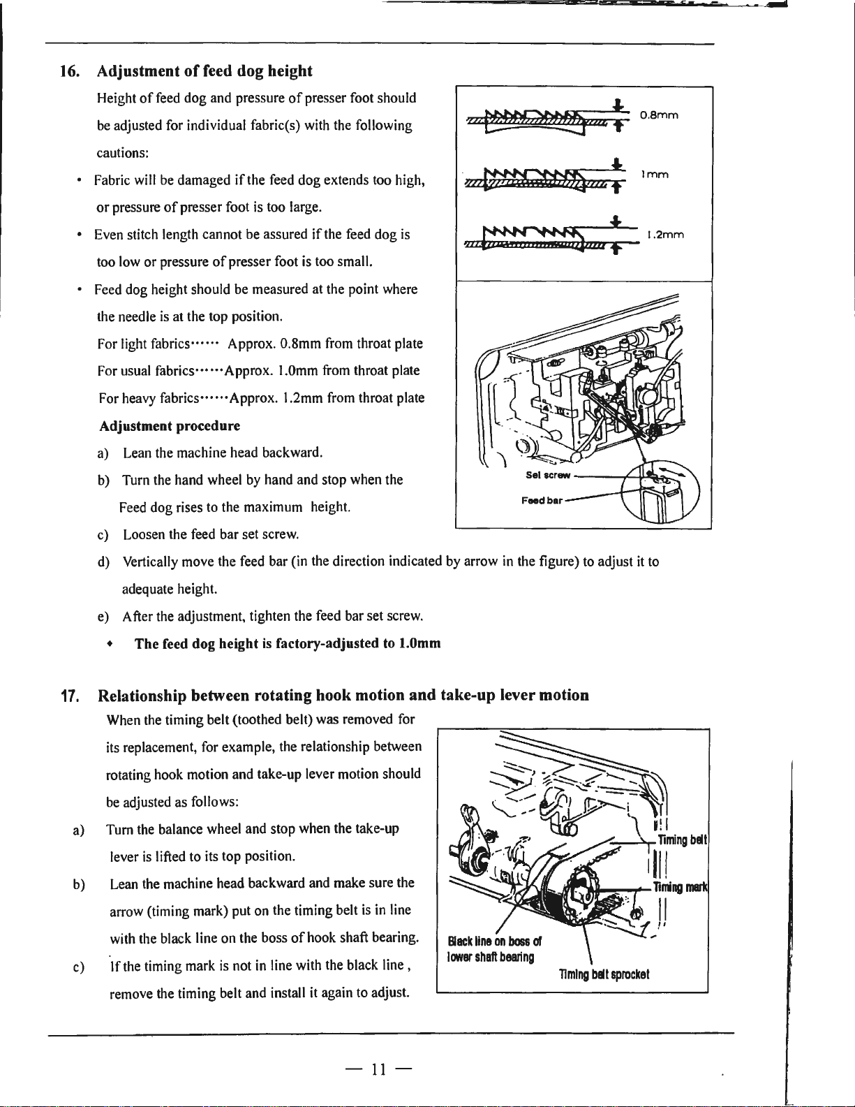
14.
Needle bar stop position (left & right)
Note: The stopper wrench can be operated while the
(I)
(2) Stop the motion
(3) Two needles running at the same time:
15.
Relations between curve angle
sure to mark the needle clamp facing left side, Tighten needle bar screw C and A
sewing Machine running, but the best way
adjust while Take-up lever stopping at its highest
position.
Stop the motion
Make the stopper wrench to the position
Make the stopper wrench to the position
Press down restore plate, stopper wrench
restore to O position automatically.
in
before page.
of
left-side needle bar:
of
right-side needle bar:
and stitch length
(I)
Determine the stitch length according to
the form to obtain various.
of
(2) The needle number
can be obtained while the angle be determined.
(3) Example: While the angle is 40°,
is
2.9mm, then the outside needle number is 6.
another outside needle
if
the stitch
of
is
to
L.
R.
The
(while the
~
ourv:"'
anal•
40·
so·
so·
I
10·
80"
90·
100"
no·
120·
130·
of
adjustment
/
/
is
';
0.3
mm
I .
~\~
•
:;,;.,_ \ j--Stoper
.,,
;
_,.
\.
-\'
Bu,h
Inc
wrench
relation,
needle j
n_,.r
30·
b1tnen
••P
2 3
.._
5.5
4.6
3.8
3.2
2.7
2.2
1.8
1.5
ba~'!
...._
>---
needle
__
4.6
3.7
3.0
2.5
2. l
1.8
1.5
1.2
wrench
Needle nunier
(8)
atitoh
and
two
naedl11
4 5
_
:::f:
2.8
2.3
1.9
1.6 1.3
nHdle
i•
1/4)
2.7
2.
2
1.8 1.5
1.
5 1.3
1.3
----
).
..
.
number
6
4.0
----
2.9
I---
2.3
1.
9
L---·
7
3 .. 7
2.5
2.0
1.6
.,_..
8
3.0
2.2
l.
__
_
7
140"
I 1.1
-IO-
.
Page 14
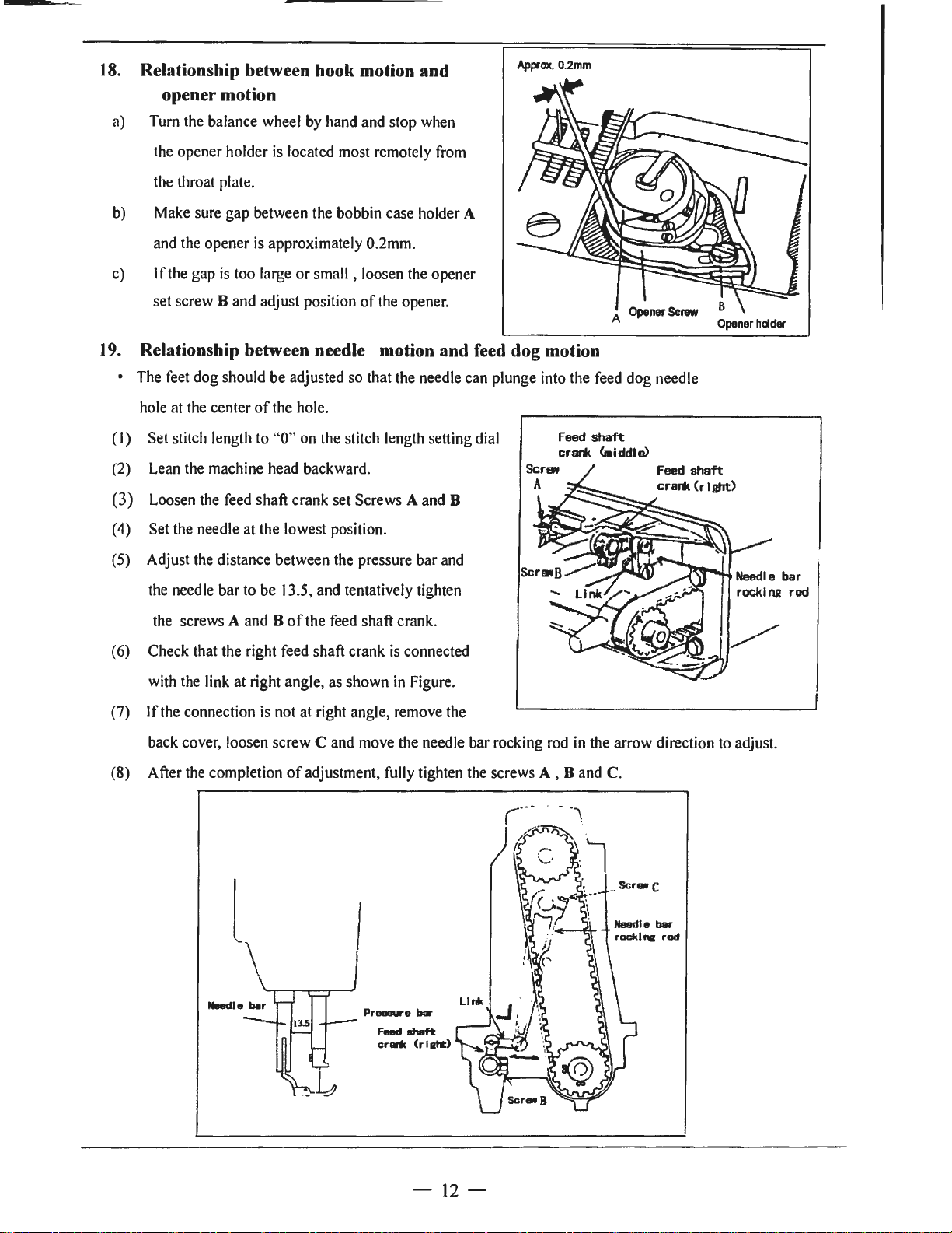
16.
Adjustment
of
feed dog height
Height
be
cautions:
• Fabric will be damaged
or
• Even stitch length cannot be assured
too low
• Feed dog height should be measured at the point where
the needle
For light fabrics······ Approx. 0.8mm from throat plate
For usual
a) Lean the machine head backward.
b)
of
feed dog and pressure
adjusted for individual fabric(s) with the following
if
pressure
For heavy fabriCS"""Approx. 1.2mm from throat plate
Adjustment procedure
Turn the hand wheel by hand and stop when the
of
presser foot
or
pressure
is
fabrics·"·"Approx.
of
presser foot is too small.
at the top position.
of
presser foot should
the feed dog extends too high,
is
too large.
if
the feed dog
1.0mm from throat plate
is
?U~mz
·~
-U~/lll:
04
! 0 .
!
8mm
1mm
1.2mm
Feed dog rises to the maximum height.
c) Loosen the feed bar set screw.
d) Vertically move the feed bar (in the direction indicated by arrow
adequate height.
e) After the adjustment, tighten the feed bar set screw.
• The feed dog height
17.
Relationship between rotating hook motion and take-up lever motion
When the timing belt (toothed belt) was removed for
its replacement, for example, the relationship between
rotating hook motion and take-up lever motion should
be
adjusted as follows:
a) Turn the balance wheel and stop when the take-up
lever
is
lifted to its top position.
b)
Lean the machine head backward and make sure the
arrow (timing mark) put on the timing belt
is
factory-adjusted to 1.0mm
is
in
line
in
the figure) to adjust
it
to
with the black line on the boss
c) If the timing mark
remove the timing belt and install it again to adjust.
is
not
of
hook shaft bearing.
in
line with the black
line,
-
11
-
Timing
belt
sprocket
Page 15
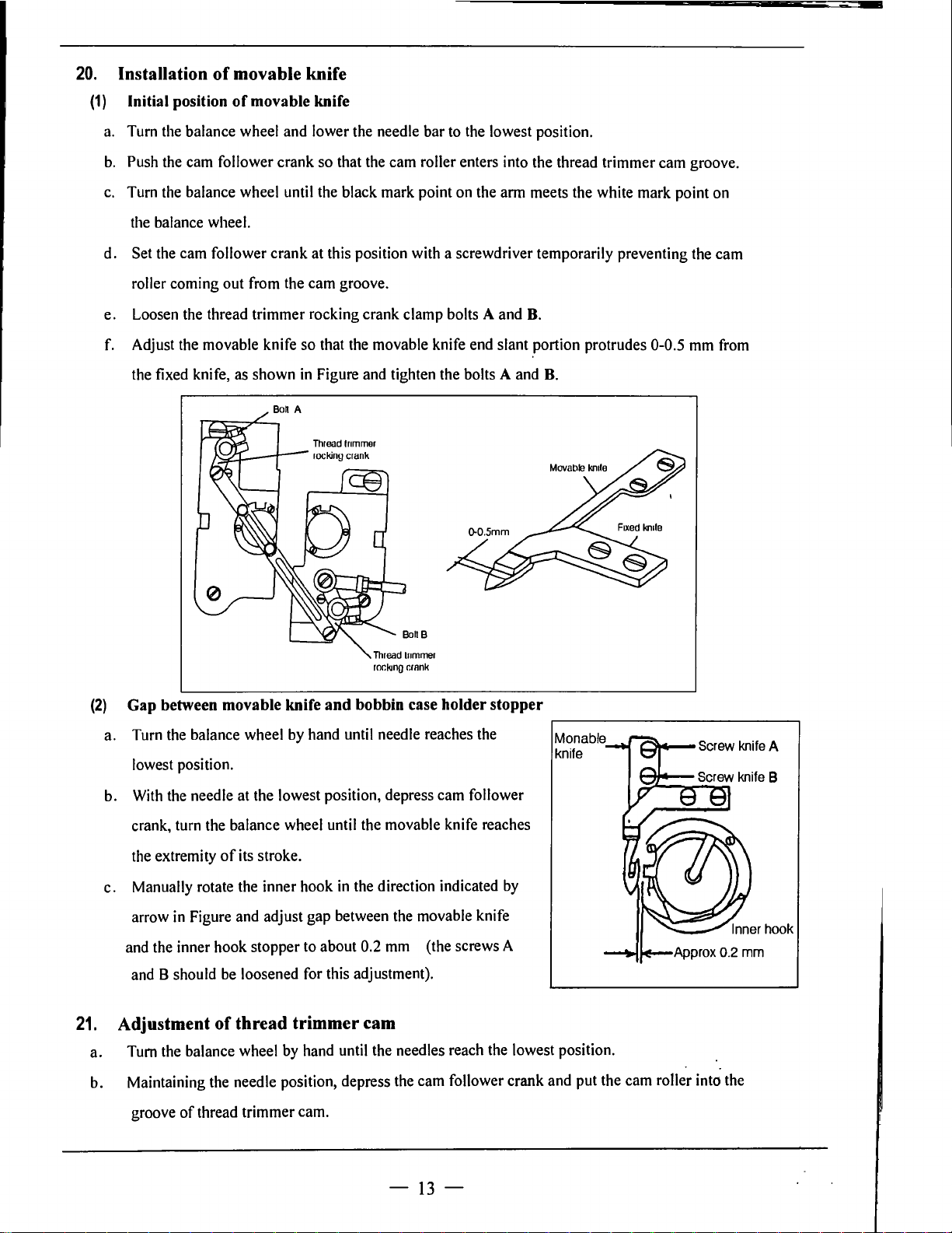
18.
Relationship between hook motion and
opener motion
Approx.
0.2mm
a) Turn the balance wheel
the opener holder
by
hand and stop when
is
located most remotely from
the throat plate.
b) Make sure gap between the bobbin case holder
and the opener
c)
If
the gap
set screw
19.
Relationship between needle motion and feed dog motion
is
is
too large
Band
adjust position
approximately 0.2mm.
or
small , loosen the opener
of
the opener.
A
A
Opener
• The feet dog should be adjusted so that the needle can plunge into the feed dog needle
hole at the center
(I)
Set stitch length to "O" on the stitch length setting dial
of
the hole.
Feed
crri
shaft
<middle)
(2) Lean the machine head backward.
(3) Loosen the feed shaft crank set Screws A and B
(4) Set the needle at the lowest position.
(5) Adjust the distance between the pressure bar and
Screw
Feed
crar* (rlafrt)
Opener
shaft
hdder
the needle bar to be 13.5, and tentatively tighten
the screws
A and B
(6) Check that the right feed shaft crank
with the link at right angle, as shown
If
(7)
the connection
of
the feed shaft crank.
is
connected
in
Figure.
is
not at right angle, remove the
back cover, loosen screw C and move the needle bar rocking rod
of
(8) After the completion
adjustment, fully tighten the screws A , Band C.
Pressure
Feed
crlrit
bar
shaft
(rllht)
in
the arrow direction
to
adjust.
-
12
-
Page 16
20.
(1)
a.
b.
c.
d.
Installation
Initial position
Turn
the
balance wheel
Push
the
cam
Turn
the
balance wheel
the
balance wheel.
Set
the
cam
of
movable knife
of
movable knife
and
follower crank
until
follower crank
lower
the
so
that
the
the black
at
this position
needle bar
cam
mark
to
the
lowest position.
roller enters into the thread trimmer
point
on
the
arm
meets the white mark point
with
a screwdriver temporarily preventing the
cam
groove.
on
cam
roller coming out
e.
Loosen
f.
Adjust
the
(2)
Gap between movable knife and bobbin case holder stopper
a.
Turn
lowest
the
the
fixed
knife,
the
balance wheel
position.
from
the
cam
groove.
thread trimmer rocking crank clamp bolts A
movable knife
as
shown
so
that the movable knife
in
Figure
and
tighten the bolts A
Thread
lr1mmer
rocking
crank
ror.kmg
by
hand
until
needle reaches
r.rnnk
and
B.
end
slant portion protrudes 0-0.5
and
B.
the
~-----------~
Monable
knife
mm
from
b.
With
the
needle
at
c.
21.
Adjustment
a.
b.
the lowest position, depress
turn
crank,
the
extremity
Manually
arrow
and
the
and
8 should
Tum
the
the balance
of
rotate the inner hook
in
Figure
and
inner hook stopper
be
of
thread trimmer cam
balance wheel
wheel
its
stroke.
adjust
loosened
by
until
the
in
the
gap
between
to
about
0.2
for
this adjustment).
hand
until
the needles
movable
direction indicated
mm
Maintaining the needle position, depress the
groove
of
thread trimmer
cam.
-
cam
the
movable
(the screws A
cam
13
follower
knife
reaches
by
knife
reach
the
lowest position.
follower crank
-
and
put the
cam
roller
into
the
Page 17
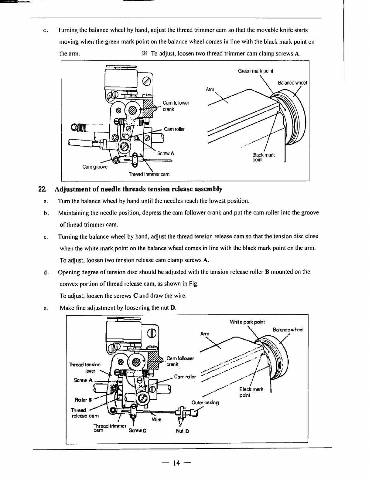
c. Turning the balance wheel by hand, adjust the thread trimmer cam so that the movable knife starts
moving when the green mark point on the balance wheel comes in line with the black mark point on
the arm.
QI[-
22.
Adjustment
a. Turn the balance wheel by hand until the needles reach the lowest position.
b. Maintaining the needle position, depress the cam follower crank and put the cam roller into the groove
of
thread trimmer cam.
·-
of
needle threads tension release assembly
* To adjust, loosen two thread trimmer cam clamp screws A.
Green
mark
point
Cam
follower
Black
maik
point
Thread
trimmer
cam
c.
Turning the balance wheel by hand, adjust the thread tension release cam so that the tension disc close
when the white mark point on the balance wlieel comes
To adjust, loosen two tension release cam clamp screws
d. Opening degree
convex portion
To adjust, loosen the screws
e.
Make fine adjustment by loosening the nut
of
tension disc should be adjusted with the tension release roller B mounted on the
of
thread release cam, as shown
C and draw the wire.
in
D.
Fig.
in
line with the black mark point on the arm.
A.
White
park
point
(II)
,
Thre&I
trimmer
cam
ScrewC
-
14
-
Page 18

23.
Adjustment
a.
Loosen the fixed knife bracket clamp bolt A.
b.
Turn the vertical positi~n adjusting screw B to adjust meshing pressure and then righter the hexagon
of
meshing pressure
of
movable knife and fixed knife
socket head cap screw
Note: Since excess pressure causes large
torque to the thread trimming mechanism
and trimming failure, adjust it so that
thread can be trimmed with minimum
pressure.
c. Move the movable knife and check that
the thread can be sharply trimmed.
24.
Sharpening
When the knives dull, the fixed should
be sharpened as illustrated
it
Since
replace it with a new one when it dulls.
of
is
very difficult to sharpen the movable knife,
A.
fixed knife
in
Fig.
Fixed
br-acker-
Hexacon
cap
scr-ew A
knife
socket
head
Ver-ti
cal
position
adjustinc
scr-ew B
25.
Adjustment for change
(I)
Replace the throat plate, feed dog and needle clamp.
(Since the throat plate and feed dog are special parts designed for thread trimming machine, be sure
to
use those specified by us.)
(2) Lean the machine head backward.
(3) Loosen two connecting link clamp bolts
(4) Remove the spring M.
(5) Loosen the hook bracket clamp screws A and
(6) When the needles and hooks have been adjusted, install the spring
(7) Contact the rocking cranks C and D to the stopper pins E and F and tighten the connecting link
clamp bolt
(8) Turn the balance wheel
(9) Loosen the nuts G and
( I
0)
Depress the cam follower crank Kand adjust the connecting rod L
smoothly enter the groove
J.
of
needle gage
J.
Band
adjust gap between each needle and hook.
by
band until the needles reach the lowest position.
H.
of
thread trimmer cam
..
Then tighten the nuts G and
M.
so
that the cam roller can
H.
(
11)
Adjustment
i.
Push the cam follower crank K so that the cam roller enters into the cam groove.
ii.
Turn the connecting rod
of
the cam groove and the cam roller
Land
adjust the clearance between the cam roller and the cam
-
15
-
Page 19

groove surface N as small as possible, and tighten the nuts G and ff.
111.
Push the cam follower crank K again and check that the cam roller enters into the thread
trimmer cam groove smoothly.
Screw
A
Connecting
link
Bolt J
Stopper
pm
--
F Thread trimmer
rockinA crank
D
Screw B
Lower
shalt
26. Wiper adjustment
a)
Run the machine then stop at
b)
Loosen the screw C ,then adjust the base block so that the line A and the line Bare
the same plane, then tighten the screw C.
c). Loosen the screw F, then adjust the wiper move so as the E clearance
Tighten the screw
F.
"up"
Lower
of
Arm
position.
plane
is
2mm, then
.,---t--,O
Screw
~2mm
Wiper
-
16-
Page 20

SPECIFICATIONS
Model
Application
Max. sewing
speed
Stitch length
Needle-bar stroke
Presser-foot stroke
Needle No.
Rotating hook
GC20528
Light to medium heavy material
-M
GC20528-M
3500rpm
0
,.._,
5mm
13mm by Leg
DP
X 5
11
#-14#
Standard
vertical-axis
hook
with
self-lubrication
Auto lubrication Large
hook (Thread
trimming)
-D
32mm
GC20528
-B
Medium heavy material
3000rpm
0
-----
7mm
by
hand
DP
X 5 18#-22#
hook
with
bobbin
thread full-rotating)
pull-back
GC20528
7mm
(Horizontal
-B-D
.,
Large
Auto trimmer
Thread take-up
lever
Stitch adjusting
system
Lubrication system
Motor
Standard
Needle
gauge
Special
--
Clutch
370W
motor
3.2
.J
Slide
Dial
Automatic lubrication
Servo motor
550W
6.4mm
4.
8 8
lever
Clutch
--
370W
9.5
motor
12.
.J
Servo motor
550W
7mm
- 17 -
Page 21

A.ARM
BED
1
AND
ITS
(I)
2 3 4 5 6 7 8 9
ACCESSORIES
10
11
(9)
15
16
17
(I)
35
34
33·
32
(9)
1
-
18
-
Page 22

A.ARM BED AND ITS ACCESSORIES
Fig.
No.
Part No.
A0I H3200B2l90 Rubber plug
1-
14715B8001
A0I
A02
1-12400B2080
H2400B2060 Spacer I I
J\03
A04
1-13200B2060 Oil guard plate I I I
J\05
H2400B2050
1-13200B2070
A06
J\07
H3000O2l60 Screw 2 2
A08
11409060080
A09
I-IA300C2030
AI0 H3200B2030
All
1-13200B2050
All
H4717B8001
Al2
1-13200K0210
Al3
l-13200K0220
Al4
H3200B2040
Al5
H2000B20l0
Al6
I-IA70082060 Screw 2 2 2 2 SMI
1-12400B2100 Thread guide
Al7
J\18
H2000M0080 Cap 2
Al9
114913B800I Supporter I
J\20 l-1491288001
A21
1-1320082170
A22
H320082160 Slide plate I I I I
A23
1-13200132080
A24
11321W0066
A25
113200B2l00 Screw I
J\26 1-149158800 I
A27 1-14914B8001
A28
1-14911B8001
A29
I-IJ\30082190 Screw I I I I
A30
1-1320082120
Rubber plug
Screw 2
Oil guard plate
Thread guide
Screw
Screw
Side cover (left)
Thread take-up cover
Thread take-up cover
Thumb screw I
Special nut
Side cover (right)
Rubber plug
Screw 2 2
Screw I I I
Thread guide (middle)
Thread guide (complete)
Cover
Screw 4 4 SM9/64( 40)x6
Cover I
Screw I
A3I H3400K0020 Cover
A32
H2004J0067
H3406K065I Oil guard plate
A33
A34
H3406K0652
A35
M3400L0030
A35
H3406L0065
J\36 HA73I IC606
H3400L0070 Shaft supporter
A37
J\37
1-13410L0065
A38
H602030200
A39
H200012080 Screw
Screw
Felt
Face plate
Face plate
Screw 2
Shaft supporter
Pin 2 2
Description
Q
Q
~
I
00
N
lf"I
0
N
u
0
5
co
00
'
N
lf"I
0
N
u
0
5
~
00
N
lf"I
0
N
u
0
I
O?
00
N
lf"I
0
N
u
0
black
5 5 gray
2
2
I
I
I
I
I I
I
I
2
I I I I
15
15
11
I I I I
I
I
I
I I
I
I
I
I
I
I I
SMJ/
2
I
I
I
SM9/64 (40)
2
GB(f8 I 8 M6x8
SMI 1/64
11
black
gray
I
I
MIOx33
MI0
I
I I I I
I I I
I
2
2 2
I
SMl/4
SM I 3/64(32)x4
I
I I I I
I I I
I
SM9/64(40)x6.5
I
I
I
I
SMI
I
I
I I I I
2
2
I
I
I I black
I I
I
2 2
I
I
2 2 2
I
I
I
2
I
I
l
I
I
I
I
I
2
l
SM9/64 (
SM9/64
gray
SMI
GBrrl
SMI
Remarks
16 (28
)
(40)
x8.5
1/64 (40)
(24)
1/64 (40)
36)
C
40)
1/64
(40)
17
3x20
1/64
(40)
II
x6.5
x8
x8
x9
x8
x6.5
x7
xt2
x8
-
19
-
Page 23

B.
THREAD
TENSION
REGULATOR
MECHANISM
1 2 3 4 5 6 7 8 9
10
11
12 13
14
15 16
17
18 19
21
22
26
27
28
29
30
I
49
48
47
46 45
44
43
42
41
40
39 38
I
..
,'
I
37
-
20-
36 35
34 33 32
31
Page 24

B.THREAD TENSION REGULATOR MECHANISM
:g
al
I
I
00
00
N
N
Fig.
No.
801
802
B03
B04
B05
B06
807
B08
B09
BIO
Bil
B12
B13
B14
B15
B16
817
818
B19
B21
Part No.
H32218681 l
H322183142
H3221B6812
I
H4705C8001
H4706C8001
HA7311C306
H4707C8001
H007013050
H322186820
HA300C2030
H4708C800I
H4709C8001
H322186810
H322180685
H322l80683
HAI
1280693
H322l80684
HA7l0B0671
H322180682
H322180687
821 H330680661
B22
HAI0680676
B23
HA3l080702
824
HAI
1580703
H330082040
B24
B25
HAI
l5B70IO
HA3IOB0701
B26
HA3l0B0705
B27
H322l868l6
B28
B29
H322l80689
H3221B0686
830
B31
H32481872I
B32
H324818621
H3248IBC21
833
B34
H3248IBB21
H32481892I
B35
H32481B521
B36
H32481B821
B37
B38
H32481BF2I
B39
H32481B321
840
H324818E2I
H3248l8221
841
B42
H324818D21
Description
Screw
Tension releasing plate
Tension releasing spring
Screw
Lever
Screw
Mounting plate
Stop ring
Mounting plate
Screw
Spring
Push button
Nut
Thread tension stud
Thread tension stud
Thread tension disk
Thread tension spring
Thumb nut
Pin
Thread guide
Thread
&_uide
Screw
Thread tension releasing plate
Thread tension spring
Thread tension spring
Thumb nut revolution stopper
Thumb nut complete
Thread tension disk
Pin
Thread tension stud
Thread tension stud
Thumb
nut
Take-up spring
guide
Screw
Stopper
Thread tension post
Screw
Bushing
Plate complete
Thread take-up spring
Plate
Thread
take-up spring l
Plate complete
. I
.,.,
.,.,
0
0
M
N
u
u
0
0
2
2
1
1
I 1
1
1 I
2 2 2
2
2
I 1 I I
I I
4
4 4
2
2
2 2 2
2
3 3 3 3
I
I 1
1 1
I
2
2
1 I
I 1
2
2
2 2 2 2
4 4 4
I
I
·1
1
I 1 1
1 1
1
1 1 1
1 1 I 1 SM9/64 C 40)
I 1
1 1
2
2
1
1
1
I
I I I 1
1 1 1
l
I I I 1
0
0
I
:g
00
N
.,.,
0
M
u
0
2 2
I
c::o
I
al:,
N
.,.,
0
N
u
0
SM9/64 ( 40)
1 1
1
1 I
1
I I
SM9/64 ( 40)
I
SM9/64
1 I
1 1 GBff896
1 1
2
I 1
I
I
SMI
2 2
I I
1/64
4
2
2
SM
11/64 ( 40
I
SM9/64
1
2 2
2
2
4
I I
I
I
I
SMl/4
I
I
1 I
1
I
2 2
SMl/8
1 1
1
I
l I
Remarks
(40)
5
(40)
(40)
(40)
(44)
x3
x4.2
><4
)
x6
x6
x3.9
.5
-
21
-
Page 25

B.THREAD TENSION REGULATOR MECHANISM
co
Fig.
No.
Part No.
Description
843 H324818421 Screw
844 H324818121
Thread tension stud
845 H2004J0067 Screw
846 H322186817
Pin I
847 H322186818 Tension releasing pin
848 H320082100 Screw
849 H322186819 Stopper
~
00
N
I/'\
0
N
u
0
I
I
00
N
I/'\
0
N
u
0
I
I I
I I I
I
I I I
I I I
I I I I
I I I
I I I I
0
I
~
I
00
N
I/'\
0
N
u
0
0
CQ
ob
N
I/'\
0
N
u
0
I SM9/64
I
SM9/64 (
SM9/64
I
Remarks
(40)
x2.9
40)
x7
(40)
x6.5
-
22-
Page 26

C.ARM
SHAFT
MECHANISM
44
43-------o
42-----..jjj
41~
40~-
35
1 2 3 4 5 6 7 8 9
•
10
11
12 13
14
15 16 17
18
19
20
1-------26
21
22
23
24
25
(27)
34
33
32
31
30
29
(17)
28
-
23
-
27
Page 27

C.ARM SHAFT MECHANISM
Fig.
No.
COi
CO2
C0J
C04
cos
C06
C07
cos
C09
CIO
CII
Cl2
Cl3
Cl4 H3200E2090
Cl5
Cl6
Cl7
Cl8
Cl9
C20
C21
C22
C23
C24
C25
C26
C27
C28
C29
C29
C30
C31
C32
C33
C34
C35
C36
C37
C38
C39
C40
C41
C42
Part No.
H3404BOOI
HAl05D0662 Screw
HA307C0662
HAI0OC2060
HAI00C2070
H2405D0664
H3204BO0I I Arm
H321
HAI07H0662 Screw
HAI0OH2050
H321
H321
H321
HAI00C2020 Screw
H3406B0671
H3205C0661
HAI
H3205CI021
HAI00F2130
H3205J0662
H3205J0661
HAI
H3204J0652
HAI
H3200C2030 Cog belt
HAI04F0654 Screw 3 3 3 3
H3207C0671
H3204C0651
H6906D8001
HA704B0651
H3200E20IO
H3200E2020
HAIO0C2020
H3207E066I Presser bar guide bracket I I
H3210E0683
H3210E0682
H3210E0681
H6904D8001
H3200E2060
H3208E0672
HAIO0B21
H3200E2100 Spring
I Crank
Set screw I I
Screw
Screw I
Set screw I I
shaft bushing (left)
I IBI04 Felt
Bolt
IE0691
IE0692 Spring
IE0693
13F0684
13F0684
Knee
lifter lever (right) 1 1
Knee
lifter connecting
Pin
Blance weight
Spring flange 3 3 3 3
Screw
Pulley(upper) 1
Screw I I 1 I
Ball
bearing I I
B'ushing
Screw
Pulley
l0D0672 Screw 2 2
Pulley(lower) I I I I
Ann shaft
Arm
shaft
Bushing
Presser bar I I I
Screw I I I I
Screw
Operation plate I I
Knee
lifter lever
Knee
lifter
Knee
lifter lever left
Presser bar lifting
Presser bar lifter
IO
Screw
Description
rod
left
rod
cam
1:0
~
00
N
V\
0
N
u
0
.
-
2 2 2 2 SMI
I
I
00
N
V\
0
N
u
0
I I
I 1 I 1
I I I I
I I I I
I 1
3
3
I I I 1
1 I I 1
I 1 I I
2
I
I I
2
I I
1
I
I 1 I I
I
I I
I I I I
I I I I
I
I
. I
I
3
3
2
I
I 1 I
2
I 1 1
I
I I I
I I I
I
~
~
00
N
~
.
V\
V\
~
g
g
1
I
I I
1
3 3
3
1
2
1
I I
I I
I
I
I
I
1
I
I
1
3
1
2
I
I
I
I
I
I
Remarks
SMl/4
(40)
SMl/4
(40)
SM9/32
SM9/32
SM15/64
SMJ/16
SMIS/64
<p5x28
SMl5/64
SM
SMl5/64
6204ZZNR/5K
SMIS/64
SM
SM
SMl/8(44)x9
SMl5/64
(28)
(28)
(28)
(28)
(28)
(28)
15/64
( 28)
(28)
(28)
15/64 ( 28
1-5/64
< 28) x
(28)
1/64
(40)
xJ.5
x7
xl4
xlJ
xl4
xJ.5
x6.7
xlO
><8.5
xJ4.5
xS.5
) x I 2
IO
x
10
x6.6
-
24-
Page 28

C.ARM SHAFI' MECH
Fig.
No.
C43
C44
Part
No.
HAIO0H2120
HA309H068I
Presser spring guide I I I I
Screw
ANISM
Description
C
Ill
::E
I
00
00
N
N
....
:g
0
N
N
u
u
0
0
I I I I
I
I
::E
I
00
N
....
0
N
u
0
C
.
Ill
I
00
N
....
0
a
0
SMl/2
Remarks
(28)
x49
-25-
-
Page 29

D.NEEDLE
BAR
ROCKING
MOTION
MECHANISM
1 2 3 4 5 6 7 8 9 10
11
16 17 18
19 (17) 20
21
22 23
12 13 14 15
-
26
-
Page 30

D.NEEDLE BAR ROCKING MOTION MECHANISM
Cl
co
=¥
Fig.
No.
DOI
002
003
D04
DOS
005
D06
D07
D08
Part No.
l-12405O0663
1-1240500662
1-12405D
Oil
wick
Needle bar crank pin
1122
Oil
wick
H32422CI08 Thread take-up guide bracket
1-1342118205
1-1350480651
HAI
10D0672
1-12405D1112
1-124211D305
lliread take-up lever
Thread take-up lever
Screw
Thread take-up link I I
Plug
Description
pin
00
N
0
"'
N
u
0
009 H3409C067I Connecting link I I
D10
HAI00l-12150
Oil
H3409C0672 Bushing I I
D12
H34l0C30IP Square block
D13
H3406C067I Connecting stud
D14
H3406C0672
015
1-1602040240
016
H3400C2050
D17
1-1320480652
D18
l-13406C0673
D19
H20l2N0652 Screw
D20
H3407C0661
021
1-1323110506
D22
H3231
H32311D406 Oil wick
023
1)24
H3407C0662
Screw I I
Needle bar rocking shaft crank
Pin
Washer
Bushing 2 2
Needle bar rocking shaft
Connecting crank
Nut
ID306 I linged screw
Rocking shalt connecting
rod
I
00
N
00
N
*
0
"'
N
0
"'
N
u
u
0
0
I I
I I
I I
I
I I
I I
I I I I
I I
I
3 3
3
I I
I
I
I I
I I
I I SM9/64(40)x
I I
I I
I
I I I I
I I
I
I I
I I
I
I I
I I
2 2
I
I I I
I I
I
I I I I
I I
I I
I I
I I
I
I I SM5/16(24)x26.2
I
I I
Cl
C!l
I
00
N
0
"'
N
u
0
I
q>3
80
ljl2.5><240
I
3 SMl5/
64 (28) ><
I
GB/Tl
17 4 24
I SMl/4(24)
I SMS/16(24)
I
Remarks
11
><
16
12
-
27
-
Page 31

E.NEEDLE
48--
47
48
BAR
45-----m
MECHANISM
6 7 8
44--.u.
43
42--<Cl
41--~
40::3.
39~
38
37
36
-f.1
:2:1
33~
32
~
I
31
30
29
2s
21
20
2s
24
23 22
21
20
19
,.
'
0
-
28-
Page 32

E.NEEDLE BAR MECHANISM
Fig.
No.
Part No.
E0I H3410C3025
E02
HA305E0662
H3248IBC21 Screw
E03
H3410C301J
E04
E0S
H3410C301O
E06
H3410C3023
E07
H3441
IC110
E08
H609030220 Pin
H007013070
E09
H3410C3022
EI0
H3410C301H Holder
El
I
E12
H3410C301Q Holder
El3 H3410C301L
E14
H3410C301E
HA703R0067
EIS
E16
H3410C30IK Screw
,
El7
H3410C30ID
EIS
H3215K0693
El9
H3410C301C Screw
E20
H3410C301B
E21
H3410C3015
E22
H3410C3019
E23
H3410C3018
E24
H3410C3017
E25
H3410C3016
E26
H3204D6513
E27
H3410C3014
E28
l-134411C310
E29
H3400C2020
E30
H320012030
I
13400C20
E31
E32
1-13204D0~8
E32
H3304D065I
E33
H324818521
H34412C710 Screw
1:34
1-134412C910
~3~
1-134412C410
P4
H3441
E
31
E38
E39
IC210 Needle bar
H3410Cl264
H3410C3011
E40 H3410Cl263
E41
H3410Cl265
E42
H3410Cl262 Nut
Bushing
Screw
Spring
Oil
wick
Oil
wick
Needle bar supporter
E-type stop ring
Needle bar supporter guide
Screw
Stopper
Washer
Guide plate
Screw
Needle bar supporter
Needle bar holder (right)
Set screw
Needle
bar
Needle bar holder (left)
Spacer
Felt
Needle bar holder
Bushing
Bolt
Washer
Needle bar guide
I 0
Needle DPx5#14
Needle DPxS#
Screw
Stopper
for
Spring
Triangle
Steel
ball
Stud
Spring 2
Description
pin
holding stopper
for
needle bar supporter 2 2
18
:
needle clamp
pin
0
~
00
N
on
0
N
u
C,
I
2 2
l I
'1l
00
N
on
0
N
u
C,
I
~
I
00
N
on
0
N
u
C,
I I I
2 2
I
I I I
I I
l
l
I I I
I I
I
I I I
I I I GB/f896 7
1
I I
I I
I I
2 2
I
I
I
I I
I I
I
I I I
I I I
I I
I I
I I
2 2
I I I
I I I
I I I
I I
I I
I I
I
2 2 2
2 2 2
I I
4 4
I I I I
I I
I
1 · I
I I I
I I
4 4
I I
2 2
I I
I I
2 2
2
4
2
2
I
4 4
2 2
2 2
2 2
2 2
12 12
2 2
I I
4
2 2
2 2
2
2
12 12
2 2
2 2 2
2 2
2 2 SMS/64(64)
Q
I
a:)
I
00
N
on
0
[l
C,
SM
SM9/64(40)x6
I
I
I
I
Remarks
l 5/l 6(28)x4.5
I GB/f879. l 3x22
SM9/64(40)x4
SM9/64(40)x6.5
SM9/64(40)x5
SM3/32(
I
I
44
)x4.2
2 SM9/64(40)x3 .5
2
SM
11/64(
I
I
40)x
2
SM
I
l/8(44)x3.5
SM
1/8(
44
)x6
Sq,2.5
I 2
-
29
Page 33

E.NEEDLE BAR MECHANISM
Fig.
No.
E43
E44
E45
Part No.
H34l0Cl261
H344l2C310
H34412C210
E46 H34412CI
E47
H344l2C5l0
E48
H344l2C810
Nut
Pin 2
Sleeve
10
Spring 2
Pin
Screw 2
Description
~
I
00
N
,r\
0
N
u
c.,
2
2
2
0
co
00
N
,r\
0
N
u
c.,
I
I
~
00
N
,r\
0
N
u
c.,
2 2 2
2
2 2
2 2 2
2 2 2
2 2 2
2
2 2
0
I
co
I
00
N
,r\
0
N
u
c.,
SM5/64(64)x6
M5.5x5
Remarks
-
30
-
Page 34

F.NEEDLE
BAR
CONTROL
MECHANISM
2 3 4 5 6 7 8 9
11
12
13
14
18
36 35 34 33 32 (4)
31
30 29 28 27 26 25 24 23
-
31
22
21
20
-
19
Page 35

F.NEEDLE
BAR
CONTROL MECHANISM
Ill
~
00
Fig
No
FOi
F02
F03
F04
F05
F06
F07
F08
F09
FIO
FIi
Fl2
Fl3
Fl4
FIS
Fl6
Fl7
FIS
Fl9
F20
F2I
F22
F23
F24
F2S
F26
F27
F28
F29
F30
F31
F32
F33
F34
FJS
F36
F37
F38
F39
F40
.
.
No.
H3400D2030
H3405D0663
H3400D2120
HA731
ICC06
H340SD0661
H0030S70SO
Screw 2 2 2
Ball
joint 2 2 2
Cover
Screw
Connecting
Nut 2
Description
rod
H3416D0692 Screw I I I
H3416D0691
HAI00821
H322186810
H34321D407
H609030180 Spring
H34321D207
H34321Dl07 Stop motion control
H3400LOOSO
Arm
IO
Blot I I I I
Nut
Shaft
pin
Pinching bushing I 1 I I
lever
Thread guide I I I I
H2004J0067 Screw 2 2 2 2
H3400D2060
H3407P067I
H3408D0681
Pipe I I
Pin
Pin
H3408D0686 Lever position plate I I
H3408D0682
H0070l3040 E
H3408D0684
H3408D068S
Spring I I I I
type
stopring
Lever
Pin
H3400D2100 Spring I I I I
HA300C2030
H3400D2090
H3400D2080
H3400D2I
H3410C3021
H3404D06S2
H3404D06S3
Screw 2 2 2
Plate
Pipe
IO
Screw
Cam
Guide
pin
Pin I I 1 I
H3404L06SJ Washer
H3404D06SS
H3404D06S7
H3404D06S6
H3404D06S8
H3404D06S4
H3404D06SI
H3404L06S2
Pin 2 2
Spring 2 2 2 2
Cap
screw 4
Spring 2 2 2
Pin 2 2 2
Guide
Bushing
00
N
on
0
N
u
0
'
'
N
on
0
N
u
0
I I I
2 2 2 2
I I I 1
2'
I I I
I
I
I
1 I
I 1 1
I I
I I I
I I I I
1 I 1
1 I 1 I
I
1 1
I
I
I I
1 I 1
I .
I I
I I I I
I I
4
I
I
I I I
Q
'
~
00
'
N
on
0
N
g
2 2
I I
1
1
1
I
I
I I
2 2
4
1
Q
'
Ill
00
'
N
on
0
N
u
0
SMl l/64(40)x9.5
2
2
JKM5
I
SM9/64(40)x6.5
MS
SMI 1/64(40)x6.6
I
I
SM
I S/64(28)x I 0
SMI 1/64(40)
I
I GB/f879.I
I
SMI
l/64(40)xl
I
I
I
I
GB/f896 4
I
SMI l/64(40)x8
2
I
I
SM9[64(40)x
I
I
SMS/16(28)x4
4
2
2
I
I
.
Remarks Part
Jxl8
1.4
12.5
-
32-
Page 36

G.STITCH
REGULATOR
MECHANISM
33
2
3 4
5
6 7 8
(7)
9
10
11
12
13 14
15
29
30
28
27
26
-
33
25
24 23
-
22
21
20
19
Page 37

G.STITCH REGULATOR MECHANISM
Fig.
No.
G0I
G02
G03
G04
G05
G06
G06
G07
G08 I IA
G09
GI0
GI0
Gil
Gl2
Gl3 IGl4
Gl5 H3216F0071 Reverse sewing lever (complete) 1
015
Gl6
Gl7
Gl8
Gl9
020
G21
G21
G22
G23
G24
G25
G26
G27
G27 H3304F
G28
G29
G30
G31
G32
G33
G34
G35
Part No.
M3204F0651
IIAI 13F0684
I 13200F2020
1-13206F0661
1-13206F0662
1-13200F2060
1-16904F8001
l-
13200F2
I I 0
I 00F2080
I-IA700F2030
1-13207F0671
l-14905G8001
I-IA800F2020
Feed regulator
Screw
Screw I I
Connecting
Eccentric shall
Reverse stitch shall I
Reverse stitch shall
Spring
Pin
Pin
Arm
Arm
Screw I I I I
Description
link
I 13207F0672 Screw
IAIO0F21
HAI
I0 Spring washer
13F0684 Screw
H4906G800I Reverse sewing lever
IH207F0673 Spring I 1
H3200F2050 Bracket for spring I
I-IA300C2030
I-IA720F0686
HA720F0685
H8504H8001
H9204F8001
HA7421Fl20
Screw
Screw
Bushing I I
Stitch length indicating plate
Stitch leng
th
indicating plate
Dial I I
HA720F0683 Stopper pin releasing lever I I
HA720F0687 Coil spring
HAI09F0671
HAI09F0673
Screw bar
Screw
H3213F0702 Dial
0651
Di
al
H3206F0662
H3210F0681
Bolt
Sc
rew
H32l0F0683 Stitch regulating crank lower
H3200F2080
Holding plate
of
reverse bar I
HA703R0067 Washer
H3212F0692
H3208G0672
1-13212F0691
Rev
erse bar
Square block 2 2 2
Guide plate
Cl
~
00
N
If'\
0
N
u
i:.,
ca
00
N
0
""'
N
u
i:.,
I
I
~
00
N
If'\
0
N
u
i:.,
I I I
2 2 2 2
I
I I
I
I
I
I
I
I I
I I
I
I
I
I I
I
I
I I
I I 1 1
I
I
2 2
I
I I
I
I
6
5
6
I I
I
I
I I I
I
I
I
1
1
1 I
1
2 2 2
1
I
I
2
I
I
I
I I
2
1 1
I I
I I
2 2
Cl
~
00
N
If'\
0
N
u
i:.,
I
SM
15/64 ( 28)
SM
I
I 5/64(28)x I 2
I
I
I
SMl5/64
SMl l/64(40)x8.5
SM
15/64
I
SM
5
11/64(40)•8
SMJ/16(28)"
I
I
I
SM3/6(28)x8
SM
l/4(40)x8
M5
2
·,6
I
2
Remarks
><8.5
(28)
xl6.5
( 28) x8.5
12
-
34
-
Page 38

H.
LOWER
SHAFT & FEED
ROCK
SHAFT
MECHANISM
49
48
2 3 4 5 6 7 8 9
26
27
28 29
LL
10
11
12
13
14
41
-
35
-
Page 39

H.LOWER SHAFT &
Fig.
No
1101
1-102
1-103
1-104
HOS
1-106
II07
1-108
1-109
Part No. Description
.
1-13213213104
1-132132B204
1-132001-12010
H3205H0655
1-132051-10654
1-132143B104
1--132132B204
1--132154B104
HA700F2l00
Lower shall bushing lcli
Oil
wick I I
Lower shall
Feed
lifting
Screw
Lower shaft bushing right I
Oil wick I
Lower shall bushing middle I
Screw
FEED
cam
ROCK
SHAFT
HI0 H3208G0674 Screw 2
MIi
1-132372G208
1-
112
H32372G408
Hl3
l-l32372G308
1-114
H32372GI08
1-114
H3305GI0I I
1-115
1-13231
HAIO0C2020 Screw I
Hl6
1-117
1-12405D0664
1-118
H3208G0675 Nut 2 2 2 2
1-119
H3208G0676 Screw
H20
H3208G0673 Connecting
H21
HAI05D0662
H22
H3208H0662
H23
H3208H0661
H24
H3200H2060
H25
HA73
I IC306
H3205GI
H26
H26
H4942H8001
H27
HS90131005 Screw
H3205G0662
1-128
H29
H32243G205
H2012N0652
H30
H31
H3407C0663
H3407C0664 Pin
H32
H242l
H33
1-134
1-13204B0656
H35
HAI08G0661 Collar
HAl05D0662
H36
H37
H3204G0651
H3204G0652 Felt
H38
H39
HAI00G2120
H40
HAI04G00l2
H41
H3205GI032
Washer I
Feed connecting
rod
Needle bearing I I I
feed
IGI08
Lever
Lever
Link
feed
connecting
connecting
cam
cam
Screw
rod
crank
Screw 2 2 2 2
Bushing I
Ball bearing
Bearing holder I
Screw 3 3
111
Feed bar I
Feed bar I I
Oil
wick
Feed
bar shaft I I
Screw 2 2 2 2
Feed
rock shaft crank
Oil
1D405
wick
Feed
rock shaft crank (right)
Screw
Feed
rock shaft I
Feed rock shaft bushing (left)
Screw 2
Feed
rock shaft Crank (left) I I
MECHANISM
a
~
O?
I
00
00
N
N
.,..,
'"
0
0
N
N
u
u
0
0
I I I I
I
I
I
3
3
2 2 2
I
I
I
3
3 3 3
I I
I I
I
I I
I
I I
I I I I
I
I I
2
2
4 4
2
2 2 2
I
2
I
~
I
00
N
.,..,
0
N
u
0
I I
I
I
I I
I I I
I I I
I I
I
I I I
3 3
I I
I
I I I
I
I I
I
I I
I I I
I I
I I
I I
I I I
I I
I
3 3
I
I
I I I
I
I
I
I I
I I
2 2
4 4
I I I
I I I
2 2
Cl
~
00
N
'"
0
N
u
0
I
I
SMl /4(40)
SMI
SM
K32x37
I
SM 15/
SM 15/
SM 1/4(24)
SM 15/64(28
SMl/4 (40) x6
I
6004ZZNR/5K
SM9/
M5
x5
I
I
SMl/4 (
I
SMl/4 (
SM3/16 (28
Remarks
l/
64(40)x7
1/4(24)•
xl3
64 ( 28
64 ( 28
64 (40
24
40
><
5
22
)x
) x7
) '
) Y4
) ~ 12
) x I 0
) x
14
14
16
- 36 -
Page 40

H.LOWER SHAFT & FEED ROCK SHAFT MECHANISM
Cl
Cl
i
O?
I
00
00
N
N
tr,
tr,
0
0
N
N
u
u
0
0
I I GBff97. I 6
I I
I
Fig
.
Part
No
.
1141
142 l-1320SG0662
11143
1-144
1-145
1146
1-147
1-148
1-149
1150
HSI
No.
H490SH8001
l-1320002030 Holder
1-132001-12040
H005001060 Washer
HS90131951
1-1003056030
1-132051-10651
1-132051-I06S2
1-132051-10653
1-1322110205
co
~
I
00
00
N
N
tr,
Description
tr,
0
N
u
0
0
N
u
0
Feed rock shaft Crank (lefl) I I
I
Oil wick
I I I
I I I I
Bolt
I I I I
I I
Screw
Nut
Feed bar connecting
Felt
Screw
Bolt
fork
I I I I
I I I I
I I I I
I
I
I I I
I I I I
Remarks
SM
15/64(28)x
M3
xl4
M3
SMl/8(44) x4
SM
1/8(
40) ><7
18
-
37
-
Page 41

I.HOOK
GC20528-B/D
SADDLE
MECHANISM
7
6
4
3
2
1
GC20528-M/B-D
7
____
_
8
9
10
29
33
-
38
-
Page 42

I.HOOK
Fig.
No.
IOI
IOI
IOI
IOI
I02
103
104
104
104
104
105
105
106
106
106
106
107
l07
107
107
108
109
110
111
111
112
112
113
114
115
115
116
117 I IA
118
118
119
119
120
121
122
123
124
125
Part No.
11320410651
I
1330410651
1-169041-18001
I
149061800
113207I0661
11320710066
1-
1340510652
1-1350012010
11850417101
H9304J7101
H69061-l8001
1-
149221800
1-12400\2020
1-
1330610067
H8505l8001 Bobbin
1193051800
1-1340610671
11350510651
1-1850618001
1-19306]8001
l-13204\0656
11321531504
H32153l204
11321531304
11331311204
1-1321531104
1-1331311104
1-1200410067
1-
1320012030
11220012020
113305\0066
11005008050
I 0400658 Nut
1-
1321211304
1-1331211204
1-1340410011
11331211104
1-1320410657
1-1321421204
IIA
I 05D0662
l-1321421104
H320410653
H2013J0065 Washer 2 2 2 2
SADDLE MECHANISM
Description
Hook saddle (right)
I look saddle (right) I
Hook saddle (right)
Hook
I
I Spring
I
saddle (right) I
Screw 2
Bushing 2
!-look
complete
Hook complete
Hook
complete
I-look
complete
Spring
Bobbin
Bobbin
Bobbin
Bobbin case
Bobbin case
Bobbin case
Bobbin case
Oil
wick
Bobbin case opener holder
pin
Screw 2 2
Link
Link
Bobbin case opener holder 2
Bobbin case opener holder
Screw 2
Washer 2 2
Opener
Opener
Spring washer 2
Spacer
Spacer
Hook
shaft bushing (upper)
Hook
shall bushing (upper)
Screw 2
Gear (small)
Screw
Gear (large) 2 2
Hook shaft bushing (lower) 2 2 2 2
0
.
I
~
.
00
N
V)
0
N
u
0
~
00
N
.,.,
0
N
u
0
co
00
N
V)
0
N
u
0
I
I
2 2 2
2
2
2
2
2
2
2
2
2
2
2
2 CP-12C
2 2
2
2 2 2 2
2
2
2
2 2
2
2 2
2 2 2
2
2
2
2 2
2 2 2 GB/T93 5
2 2 2
2
2
2
2 2
2
2
2
2
2
2 2
6
2 2
6 6
6
2
0
~
00
N
V)
0
N
u
0
SM
I 5/64(28)xJ0
2
HSH-l2-15M
2 HSH-12MC
2
BO-J
(2
..,
'
.,.,.
80-1-12
2
CP-12MC
2
2
SM3/16(32)x7.8
2
SM9/64
2
SM3/l6(32)
2
SM3/16(28)x
2
SMl/4
(40)
2
~
~
...
I~
=--
I
I
Remarks
(3)
(3)
(A.)
M
(A)
M
(3)
(40)
x7
14.5
x4
-
39-
Page 43

I.HOOK SADDLE MECHANISM
Fi
g.
No.
126
127 1·1320410658 Screw
128
129
130
131
132
133
133
133
133
Part No. Description
11320012050 Screw
l-1320410659
I !005014050
HA305E0662
HA307C0662
1-13204165
H3209I0671 Hook saddle (lefi)
1-13307!0681 I-look saddle (lefi)
ll6905H8001
1-1491718001
Nut
Spring
washer
Screw
Screw
IO
Screw
Hook saddle (lefi)
I look saddle (lell)
~
00
N
Ir)
0
N
u
0
00
N
V)
0
N
u
0
:i
00
N
V)
0
N
u
0
I
0
Cl;l
2 2 2 2
2 2
2 2
2 2 2 2
2 2 2
4 4 4 4
2 2 2 2
2 2 2 2
I
I
I
0
~
00
N
V)
0
N
u
0
SMl/4(24)x23
SM3/16(28)x43
SM3/16(28)
GB/T955
2
SM
SMl/4
SM
I
Remarks
15/64 (
(40)
1/4(
40)x6
5
28)
.5
x4.5
x6
-
40
-
Page 44

J.UPPER
3
FEED
ROCK
SHAFT
4 5 7 8 9
MECHANISM
(15)
(14) (11)
-
41
-
..
••••
t
Page 45

J.UPPER FEED ROCK SHAFT MECHANISM
~
Fig.
No.
JOI
J02 1149061800 I
.103
104
105
106
107
108
109
J
J
112
113
114
JI 5 H4920J8001
116
.117
Part No.
H4905J8001 Screw
Bolt 2 2
114907J8001 Trimming knife holder
1149081800 I
1·14909J800 I
Screw
Fixed blade 2 2
H4914B8001 Screw
11491
IJ8001 Move knife 2 2
11491218001 Screw
I-14913J8001 Screw
10
H49l4J8001 Spring plate
II
1·14915J8001
Screw
H4916J8001 Reversing spring 2 2
f-1690518001
H49l7J800I
Gulde (left)
Gulde (left)
Roller 2 2
H492IJ8001
Lever 2 2
H4922J8001 Cover (right)
Description
Jf 8 H690418001 Guide (right)
119
H4923J8001 Guide (right) I
J20 H4924J800I Knife pad (right)
J21
H4925J8001
J22
I-14926J8001 Knife pad (left)
J23
H4927J8001
Screw I
Cover (left)
00
N
II")
0
N
u
0
Cl;!
00
N
II"\
0
N
u
0
a
i
I
00
N
II"\
0
N
u
0
2 2
2
6
4 4
2 2
2 2
2 2
6
I
I I
I
I
I
I
a
C9
00
N
II")
0
N
u
0
2
6
6
I
I
I
I
I
SM9/64
SM9/64
SM9/64 (
SM 1/8 (
SM9/64
SM3/32
SM9/64 (
Remarks
(40)
x7
(40)
x5
40)
x4
40)
x9.2
(40)
x4.5
(56)
x3.8
40)
x9.5
-
42
-
Page 46

K.
KNIFE
MECHANISM------~
36
37 38
8 9 10
6 7
61
l---34
~35
51
56
63
64
-
43
-
Page 47

K.KNIFE MECHANISM
0
co
00
N
V)
0
N
u
0
I
~
I
00
N
0
"'
N
u
0
2 2
I I
I I
I I
4 4
I I
I
I I
I I
I I
2 2 GB/T6170
I
I I
2 2
I I
I I
I I
I
I I
~
00
Fig.
No.
KOi
K02
K0J
K04
K05
K06
K07
KOS
KOS
K09
KIO
KIi
Part No.
HA300C2030 Screw
H4915K7101
1-14918K8001
1-14919K7101
1-1240012040
HA300B2170
H4923K7101
H6907J8001
H4912K8001
H4913K8001
Thread releading bracket I I
Spring
Thread releasing
Screw
Screw
Flexible wire complete
Arm
Arm
Bolt
H4945K8001 Spring
H4950K8001 Screw I I
Description
N
V)
0
N
u
0
Kl2 H4949K8001 Roller
H4952K8001 Screw I I
KIJ
Kl4 H4953K8001
HA708P0668 Nylon clip I I
Kl5
Mounting plate I I
Kl6 H6905J8001 Mounting plate I I
1-1003002050
Kl7
Kl8
H6906J8001
Kl9 H4908K8001
H4907K8001 Bolt I I
K20
K21
H4906K8001 Link
K22
H4905K8001
K23
HAI00H2080
K24
H4946K7101
K25
H4943K8001
K26
H4951K8001
H4954K8001
K27
K28
H4956K8001
K29
H4955K8001
K30
H4957K7101
K31
H4944K8001
K32
H3205GI
K33
HA708P0668
K34
HAI
13F0684 Screw 2
K35
H6904J8001
K36
H4909K8001 Link
K37
H005001050 Washer
K38
H491
IK8001 Bolt 2
K39
H4936K8001
K40
H4987K8001
K41
H4940K8001
K42
H4939K8001 Bolt I I
Nut
Screw I I SMJ/
Arm
Screw
Pin type I I
Thread releasing lever I I
Spring I I
Nut
Nut
Screw 2 2
Bushing I I
Vibrating crank I I
Screw I I
Screw 2
114
Nylon clip I
Bushing I
Screw 2
Link screw I
Nut (left)
0
qi
00
N
V)
0
N
u
0
SMI
SMI
SMI
Remarks
1/64
1/64
1/64
I
SM
15/64
SMI
1/64
SMJ/16
16
(28)
02)
I
SM
15/64
M5t0.5)x7.5
1/64
SMI
(28)
(44)
1/64
2
SMJ/16
SMl/8
SMI
M5x5
I
SM
2
15/64
I
I GB/T97.I
2
2 M5(0.5)x8.5
I
M5(1di)
(40)
x8
(40)
x5
(40)
Y8
( 28) ~ 12
(40)
xJ.6
x5
M5
xJ.5
( 28) x I
(40)
x7
(40)
x5.5
( 28)
x8.5
5
.5
2.5
- 44 -
Page 48

K.KNIFE MECHANISM
Fig.
No .
K43
K44
K4S
K46
K47
K48
K49
KS0
KSI
KS2
KS3
KS4
KSS
KS6
KS7
KS8
KS9
K60
K61
K62
K63
K64
K6S
K66
K67
K68
K69
K70
K71
K72
Part No.
H0030020S0 Nut (right)
H4964K800I Shaft I I
1-14963K8001
H498SK8001
H340SD0663
H320SGI
H4934K8001
Shaft
Screw
Ball
joint (right) I I
114
Screw 2 2
Cam
HA710E0692 Screw 2 2
H4932K8001
H4986K8001
H41
I0S0l60 Screw 2
Cam
Spring I
H2012N06S2 Screw I I
H4983K8001
Screw I I
H4967K800I Screw
H4966K800I Stopper I
H4981K800I Holder I I
H0030080SO
H4977K8001
H4980K8001
H496SK8001
H3700E2080
Nut 2 2 GB/T6 I
Mounting plate I I
Holder 2 2
Set plate I I
Pin type
H4969K800I Screw I I
H4970K8001
H4971K8001
H4972K8001
H4973K800I
H4974K8001
HAI
I IG0683 Screw I I SMI
HA71
I IN304
Screw I I
Lever I I
Screw I I SMI
Pin
Arm
Nut
H4979K8004 Solenoid complete
Description
~
I
00
N
1/'l
0
N
u
c,:,
co
I
00
N
1/'l
0
N
u
c,:,
Cl
Cl
I
co
i
00
N
1/'l
0
N
u
c,:,
00
N
1/'l
0
N
u
c,:,
I
I I GB/T6170
I I
SMI
M4
1/64
x4
I I
I I
SMl/4
I
I
I
GBff819. I MSx
2
SMl/4
SMl/4
SMI
3 3
1/64
I
I I
SM
11/64
1/64
SMI
1/64
I I
I I
1/64
I I SMI
1/64
I I
Remarks
MS
(40)
(40)
x
(24)
xl6
(24)
xIJ
(40)
72. I MS
( 40)
(40)
(40)
(40)
(40)
x4
9.S
16
x7
x8.S
x6
x6.8
xl2
-
45-
Page 49

L.
TOUCH
BACK
AND
2 3
DETECTOR
MECHANISM
(23)
32
31
30
-
46
-
Page 50

L.TOUCH BACK AND DETECTOR MECHANISM
co
Fig
.
Part
No.
LOI
L02 H4905L7I01
L03
No.
H4918L800I Screw
Touch switch (complete)
HA700Q0030
Cord holder
L04 H4922L800I Cord holder
L05 HA703R0065
L06 H3205J0662
H007009300
L07
HA700R0060 Washer
LOS
L09 HA700R0050
HA700R0040 Spacer B
LIO
LI
I H4928L800I
Detector bracket (complete)
Ball bearing
Retaining ring C-type
Support spring
Speed command disk F20 (up)
L12 HA700R0030 Spacer A
Ll3
H4930L800I
H493IL800I Pulley (complete)
Ll4
Speed command disk
LIS HAI 10D0672 Screw
HA703R0067 Washer
Ll6
Ll7
HA341
ID308 Screw
LIS
H4936L800I
Ll9
HAI l3F0684 Screw
Lever (complete)
L20 H4937L800I Screw
L21
H4938L800I Rubber ring
L22 H4939L8001 Spring
H4940L800I
L23
H4941L8001 Screw
L24
H4943L8001 Solenoid (complete)
L25
HI02080l20
L26
Nut
Blot
L27 H6904K800I Set plate
L28 H005008060 Spring washer
L29 H003002060 Nut
L30
H4948L8001 Link
L31
H4949L8001
H4950L800I
L32
L33
H4942L800I Nut
Blot
Arm
L34 HA300C2030 Screw
Description
Fl
I (down)
~
00
N
on
0
N
u
c,:,
I
00
N
on
0
N
u
c,:,
~
Cl
Cl
I
I
co
~
00
'
00
N
N
.
on
on
0
0
N
N
u
u
c,:,
c,:,
2 2
I
M5
I
3 3
I I
I I
I I NTN
I 1
62042
GB/f894.
I I
1 I
I I
I I
2
2
I I
I I
1 1 SMIS/64
1
I
I
1 SMIS/64
I I
I I
I I
SMIS/64
SMIS/64
I I
I I
2 2
SMIS/64
2 2 SMIS/64
I I
2 2
GB/f5781
I I
2 2
2 2
GB/f93
GB/f6170
I I
1 I SMIS/64
I I
I I SMI 1/64
2 2
SMll/64
Remarks
I 30
(28)
(28)
(28)
(28)
(28)
(28)
M8xl2
6
M6
(28)
(40)
(40)
xl2
x7
x7.5
x6
xt4
x I 3
x8
-47-
Page 51

M.
WIPER
MECHANISM
12
13
14
15
20
21
22 23
24
21
<
>
25
26
(2
I)
32
31
30
29
28
-
48
-
27
Page 52

M.WIPER MECHANISM
Fig.
No.
MOI
M02
M03
M04
MOS
M06
M07
MOS
M09
MIO
Mil
Ml2
Part No.
1-1003002030
H005009030 Spring washer
1-1005006030 Washer
1-1005004040
HA300C2030
1-16909L8001
H69IOL8001
H691
IL8001
1-16912L8001
l·l6913L800 I Collar
H6914L8001
H6915L8001
Ml3 H6916L8001
Ml4
H6917L8001
HAI
MIS
Ml6
Ml7
Ml8
Ml9
M20
M21
M22
M23
M24
M25
M26
M27
M28
M29
1100683
1-1003002040
H005009040
H692IL800I
H6922L800I
HAI00E2150 Screw
1-1409030060
1-16924L8001
HA708P0665 Switch
HA700P0060 Cord holder
1-16928L8001
H6929L800I
I-IAI04G0654 Screw
1-16932L8001
I-16930L800 I Wiper silde plate
M30 H0070l3040
M3I H6927L8001
M32
1-16931L800I
Nut
Washer
Screw
Cam
plate (complete)
Shaft
Wiper stand
Screw
Spring
Screw I
Link
Wiper crank I
Screw I
Nut
Spring washer
Stopper plate I
Cushion I
Screw 6
Solenoid plate
Rotary solenoid I
Cover I
Washer
E-type stop ring 2
Wiper shaft
Wiper
Description
~
I
00
N
Ir\
0
N
u
c.,
C1il
00
N
Ir\
0
N
u
c.,
0
0 -
I
co
I
00
00
N
N
*
Ir\
Ir\
0
0
N
N
u
u
c.,
c.,
I
GBff6170
I GBff859 3
I GBff96 3
2 GBff848 4
4
SMI l/64(40)x7
2
I
I
2
SMI l/64(40)x
I
I
SM9/64(40)x7.4
I
SMI l/64(40) xt
2
GBff6170
2 GBff859 4
2
SMI l/64(40)x8.2
GBff818 M3x6
I
I
I
SM
2
l/8(44)x6
2
I
I
I
Remarks
M3
2Q
1.4
M4
-49
-
Page 53

N.OIL
LUBRICATION
MECHANISM
12
\
--\
'
3
4567
10
11
12 13
14
15
16
17
18
19
39
23
I
38
37
(16)
(18)
(1)
(20)
36 35
(20)
-
(18)
50-
34
33
32
31
30
29 28
27
26 25
24
Page 54

N.OIL LUBRICATION MECHANISM
~
I
Fig.
No.
NOi
N02
N03
N04
N05
N06
N07
N08
N09
NI0
NII
Part No.
l·IA300C2030 Screw 3
H3200K0050 Holder I
H3210K0672 Pipe I I
H321758304 Felt
H3204K0032
H3204K0043
H3204K00l 1
Oil
pipe &
Oil
pipe &
Oil
tank complete I
H3204K0659 Gasket I I I I
H411040160 Screw 2 2 2
H4707J8001
Holder I I I I
H3204K0655 Pipe I I I
wick
wick
Description
complete
complete
Nl2 H3204K0656 Pipe I I
HA30082170 Screw I
Nl3
H3200K0040 Holder I
Nl4
l-
13209K0066
NIS
Nl6
HA7311CC06
N17
H005008030
1-132311D606
Nl8
Nl9
H3200K0l90 Holder 2 2
N20
HA30082130 Screw 7 7 6 6
N21
H3200K0200 Holder I
N22
H3230K0751
N23
H3230K0752
N24
H3215K0696 Pi
N25
11110012070
11110012090
N26
N27
11110012110
N28
113204D65l0
N29
1132 I 5K0693
N30
H32l5K0692
NJI
1132
I 5K0694
N32
l13215K4011
l-132l5K0695
N33
1-13215K0693
N34
N35
H32l0K0672
N36
H3200K0170
N37
H321
IK0068 Cover complete
N38
H3218K0072
N39
H3219K0072
N40
1-13200K0
N41
H3216K0070
N42 I 13204K0655
N43
H3200K0l60 Holder 2
Pipe &
felt
complete I I I
Screw
Spring washer
Holder
Screw
Bushing
pe
Pin
Spring
Spring holder
Screw
Screw
Filter
Screw
Base
plate complete
Holder
Screw
Pipe
Holder I I I
Oil
pipe &
wick
complete
Oil
pipe &
wick
complete
180
Oil
wick
Oil
pipe &
wick
complete
Pipe
00
N
or,
0
N
u
c.:,
I I I I
I I I
I I I
7
I I I
4 4 4 4
2 2 2
I I I I
I I I
I I I I
I I I
I
I I I
I I I
I I I
I I I
I I I I
I
I
I
2 2 2
I I
I
3 3
I I I
I I I
0
O;l
00
N
,r,
0
N
u
0
I
~
00
N
or,
0
N
u
0
3 3
I I I
I I
I I
I I
I I I
I I I
7 7 SM9/64(40)x6.5
7
2 2
I I I
I
I
I I I
I
I
I
I
I
I
I I
3 3
2
2 2
0
~
00
N
or,
0
N
u
0
SM
3
Remarks
I l/64{40)x8
I
I
I
2 GB/T819.I
M4
I
SM
I 1/64(40)x9
I
GBff93 3
I
SM
I l/64{40) x5.5
SM
2
11/64(40)>-I0
I
I
I
SM
I
I
l/8(44)x4.8
SM9/64
(40)
I
SM9/64(4Q)x7
I
I SM9/64(40)x4.5
I
I
2
I
I
I
xt6
xS
- ·
51
-
Page 55

N.OIL LUBRICATION MECHANISM
Fig.
No.
N44 H3210K0675
N45 H3210K0671 Oil pipe connector
N46 HW48887-18 Pipe I
N47 HAIO0E2150 Screw 2
N48 H3200K0250 Holding plate I
N49 H3200K0030 Holder I
Part No. Description
Holder
::E
I
00
N
or,
0
a
C,
I I
I I
0
al
00
N
or,
0
a
C,
I
I
~
00
N
.,.,
a
C,
I I
I I
I I
2 2 SM9/64(40)x
2
I I I
I I
0
I
al
I
00
N
.,.,
0
N
u
C,
I
I
Remarks
10
-
52-
Page 56

O.ACCESSORIES
14
1
8
9
~@
16~
~28
26
fL
~
12
27
I_
q
44
-
53
-
Page 57

O.ACCESSORIES
Fig.
No.
001
001 I
002
003
004
005
006
007
007
007
007
008
009
OIO
Oil
012
013 HA300J2200
014
015
016
017
018
019
020
021 HA300J2280 Screw
022
023
024
025
026
027
027
027
028
029
030
031
032
033
034
035
036
037
Part No.
1-1320400658 Needle DPx5#14
13300L0020
1-13200L0050
1-13200L0060
1-14905N8001
Needle DPx5#14
Socket wrench
Socket wrench 3 I I
Socket wrench 2 I I
l-l3404M065 I Socket wrench
l-l8504M8001
1-1240012020
1-13306!0067
1-1850518001
1-1930518001
1-1801045200
I-IA300J2230
l-l3200L0020
Socket wrench
Bobbin 4
Bobbin 4
Bobbin 4
Bobbin
Screw 4 4 4 4
Washer 4
Vibration preventing rubber 2 2 2
H3200L0030 Vibration preventing rubber 2 2
HAIO0J21
I0 Oiler I
Screw driver (middle)
HA300J2210
H3207L0651
HA704S0654
1-1409030060
H4907N8001
1-1200800068
Screw driver (small)
Thread a needle
Adjusting plate
Screw
Thread guide
Belt cover I I I I I
HA30082170 Screw
HA300J2250 Screw I I I I
1-1200800070
1-1003008040
HA305J0665
Belt cover 2 I I I I
Nut I I I I
Belt cover 3
H3200L0120 Cotton Stand I I I I
H3200L0l90 Bobbin winder I black
H3300L0040 Bobbin winder I black
HA706S0067 Bobbin winder I I gray
H3200L0l30 Oil can
HAIO0J2120
Magnet block for reservoir
HA307J0067 Hinge complete I I I I
HA300J2070
Screw driver (large)
H3214L0067 Small parts I I I I
H3214L201
I Knee lifter pin 2 2
H3213L0662 Knee lifter shaft I I I I
HA104J0657 Spring I I I I
HAI06J0664 Bolt I I I I
HA104J6510 Nut l l I I SMl5/64
Description
2.5
1/
I 6
1.5
kit
for
speed command disc
~
00
N
,,.,
0
N
u
0
0
~
I
00
N
,,.,
0
N
u
0
~
I
00
N
,,.,
0
N
u
0
6 6
6 6
I I I I
I I I I
I I
4 4
,2
I I
I I I I
I I
I
I I I I
I I
I I
I I
2
2
2
2 2
2
2
I I I I
I
I I I
I I I
I I
I I
2
Cl
I
co
I
00
N
,,.,
0
N
u
0
DPx5
DPx5-#21
4
GB/T99
4
2
2
I
I
GB/T818 M3x6
SMI l/64(40)x8
2
SM
M4x8
GB/T6172.I
I
2
Remarks
#14
4.5><20
11/64(28)"'8
M4
(28)
-
54-
Page 58

O.ACCESSORIES
Fig.
No.
038
039
040
041 HAl04J0653
042
043
044
045
Part No.
I-IA104J0659
H3213L0664
1-1007013090
HAI04J0652
1-13213L0661
HAI00J2180
1-13218L0681
Screw I I
Knee lifter crank
E-typc stop ring
Washer
Screw
Oil
reservoir I I I I
Vinyl cover I I I I
Felt I I I I
Description
Q
Q
~
00
N
or,
0
N
u
0
I I
cr:l
00
N
or,
0
N
u
0
.
I
:E
00
N
or,
0
N
u
0
I
I
I
d:i
00
N
or,
0
N
u
0
I SMIS/64
I
2 2 2 2 GBrr896 9
2 2 2 2
I
I
I I SMS/64
Remarks
(28) x27
(28) x8.2
I
. .
.
.
-
55
-
Page 59

Gauge Parts List
Gauge
Size
GC20S28-M
1/8 (3.
2mm)
3/16(4.
1/2
GC20S28-B
3/16(4.
9111111)
l/4{6.
4mm)
5/16(8mm)
3/8 (9. 5
1/ 8 (3.
1/ 4
(12. 7mm)
(6.
5/
16
(8mm)
mm)
2mm)
9mm)
4mm)
~
Needle
Plate
H3200B2220
H3200B2240
H3200B2110
H3200B2260
H3200B2270
H3200B2280
H3300B2140
H3300B2160
H3300B2020
H3300B2180
~
Feed
Dog
H3200G2100
H3200G2120
1-132211G305
H3200G2140
H3200G2150
H3200G2030
H3300G2100
H3300G2120
H3304G0011
H3300G2140
~
Presser
Foot
H3215E0066
H3217E0068
H3206E0065
H3219E0070
H3220E0071
H3221E0072
H3307E0068
H3305E0066
H3304E0065
H3306E0067
~
Needle
H3400C2080
H3400C2090 H3200B2140
H3410C3013
H3400C2100
H3400C2110
H3400C2120
H3400C2080 H3200B2140
H3400C2090
H3410C3013
H3400C2100
'am
Clamp
0
Slide Plate
H3200B2140
H3200B2140
H3200B2350
H3200B2350
H3200B2360
H3200B2140
H3200B2140
H3200B2350
(L)
'
0
Slide
Plate
H3200B2150
H3200B2150
H3200B2150
H3200B2150
H3200B2150
H3200B2150
H3200B2150
H3200B2150
H3200B2150
H3200B2150
(R)
3/8
(9.
5mm)
1/2
(12.
7mm)
GC20S28-M-D
J/8 (3.
2mm)
3/16(4.
1/2(12.
GC20528-B-D
3/16(4.
3/8 (9.
9mm)
1/4 (6.
4mm)
5/16
(8mm)
3/8
(9.
5mm)
7mm)
1/8 (3.
2mm)
9mm)
1/4(6.
4mm)
5/16(8mm)
5mm)
H3300B2190
H3300B2060
H6910B8001
H6906B8001
H6908B8001
H6914B8001
H6915B8001
H6916B8001
H9208B8001
H9210B8001
H9204B8001
H9212B8001
H9213B8001
H3300G2150
H3300G2030
H6910G8001
H6912G8001
H6904G8001
H6914G8001
H6915G8001
H6916G8001
H9206G8001
H9208G8001
H9204G8001
H9210G8001
H9211G8001
H3308E0069
H3309E0070
H3215E0066
H3217E0068
H3204E0065
H3219E0070
H3220E0071
H3221E0072
H3307E0068
H3305E0066
H3304E0065
H3306E0067
H3308E0069
H3400C2110 H3200B2350
H3400C2120 H3200B2360
H3400C2080
H3400C2090
H3410C3013
H3400C2100
H3400C2110
H3400C2120
·,
H3400C2080
H3400C2090
H3410C3013
H3400C2100
H3400C2110
H4732B8001
H4732BH001
H4732B8001
H4746B8001
H4746B8001
H4747B8001
,
H4732B8001
H4732B8001
H4732B8001
H4746B8001
H4746B8001
H3200B2150
H3200B2150
H4733B8001
H4733B8001
H4733B8001
H4733B8001
H4733B8001
H4733B8001
H4733B8001
H4733B8001
H473388001
H4733B8001
H4733B8001
1/2
(12.
7mm)
H9214B8001
H9212G8001
H3309E0070
-
56
-
H3400C2120
H4747B8001
H4733B8001
 Loading...