

Highlead GC1998 User Manual
HIGH
LEAD
GC1998 Series
High Speed
Instruction Manual
Dry
Lubricated Direct Drive Lockstitcher With
Thread
Trimmer
Parts Catalog
SHANGHAI HUIGONG
N0.3
SEWING MACHINE FACTORY


----- CONTENTS -----
1.
PRECAUTIONS
1) Safety precautions·· ............................................................................................................................... 1
2)
Precaution before Starting Operation ............................................................................................... 1
3)
Precaution for
2.
PREPARETION
BEFORE
Operating
BEFORE
STARTING OPERATION ........................................................................ 1
Conditions ................................................................................................ 1
START
TO
OPERATE
.............................................................................. 2
Adjustment
3.
PRECAUTIONS
1)
Lubrication
2) Adjustn1ent of the
3l Periodical cleaning··· .............................................................................................................................
4)
Precaution for detector ........................................................................................................................ 3
4.
HOW
TO
1) How to
2)
Threading
3)
Adjusting
-1)
Adjustment
5) Adjusting
6)
Adjusting the
7)
Adjustment of
8)
Adjustment
9)
Thread
10) How to wind the lower
11)
Adjustment
12)
Adjustment
13)
Adjustment
14)
Adjustment
15)
Adjustment
of needle
FOR
bar
stop position ............................................................................................. 2
STARTING
TO
OPERATE
............................................................................... 2
........................................................................................................ ~ ................................. 2
USE
attach
amount
THE
MACHINE ............................................................................................................... 4
needle ............................................................................................................................ 4
of oil for hook ......................................................................................... 3
............................................................................................................................................... 4
of
stitch length & reverse lever...................................................................................... 4
of the
thread
of
pressure of presser foot ................................................................................................. 5
thread
upper
of lower
wiper (for machine equipped with
of feed dog height
of remaining needle
guide .......................................................................................................... 5
tension ............................................................................................................... 5
thread tension .................................................................................................. 6
thread
tension ................................................................................................... 6
thread
thread
on the bobbin ................................................................................... 7
and
inclination ................................................................................ 7
thread
length
wiper)............................................................ 6
after
thread
trimming
....................................... 8
of feed timing ................................................................................................................... 8
of
forward/backward
stitch length· .............................................................................. 8
of knife engagement ........................................................................................................ 9
3
5.
SPECIFICATIONS .................................................................................................................................... 10
6.
PARTS CATALOG·· ...................................................................................................................................
A)
Arm
bed & Its accessories ..................................................................................................................
B)
Needle
C)
Feeding
D)
Stitch
El
Presser foot mechanism .....................................................................................................................
F)
Presser foot mechanism(Speciai
Gl
Knife
H)
Touch
I)
Wiper
Motor
Jl
K)
Oil lubrication mechanism ................................................................................................................ 37
L)
Accessories ........................................................................................................................................... 39
bar
and
thread
and
feed lifting mechanism ................................................................................................ 18
regulator
actuating
back
mechanism·· .............................................................................................................
mechanism· ..............................................................................................................
mechanism & Detector mechanism ............................................................................
take-up mechanism ....................................................................................
order)
...........................................................................................
mechanism ............. , ................................................................................................................. 33
mechanism ............................................................................................................................... 35
11
11
15
21
24
26
28
31

1.
PRECAUTIONS BEFORE STARTING OPERATION
1)
Safety precautions
(I)
When turning the
and the area around the pulley.
Power
(2)
(3)
must be turned
The
power must be turned
when replacing.
power
on, keep your hands and fingers
off
when the machine
off
before tilting the machine head, installing or adjusting the machine, or
is
not used,.
away
from the area around/under the needle
( 4) Avoid placing fingers, hairs bars etc. nears the pulley, bobbin winder pulley, when the machine
eration. Injury could result.
or
(5) Do not insert fingers into the thread take-up cover, under/round the needle,
chine is in operation.
(6) If a mini motor cover, finger guard, and/or eye guard are installed, do not operate the machine with-
out these safety devices.
2)
Precaution before Starting Operation
(I)
If the machine's oil pan has an oil sump, never operate the machine before filling
(2) If the machine is lubricated by a drop
(3) When a new sewing machine is first turned on, verify the rotational direction
power on.
(The pulley should rotate counterclockwise when viewed from the pulley.)
(4) Verify the voltage and (single
3)
Precaution for Operating Conditions
(I)
Avoid using the machine at abnormally high temperature
or
oiler,
never operate the machine before lubricating.
three) phase with those given on the machine nameplate.
(35°C
or
higher) or low temperatures
pulley when the ma-
it.
of
the pulley with the
is
op-
(SOC
or
lower). Otherwise, machine failure may result.
(2) Avoid using the machine in dusty conditions.
-1-
2.
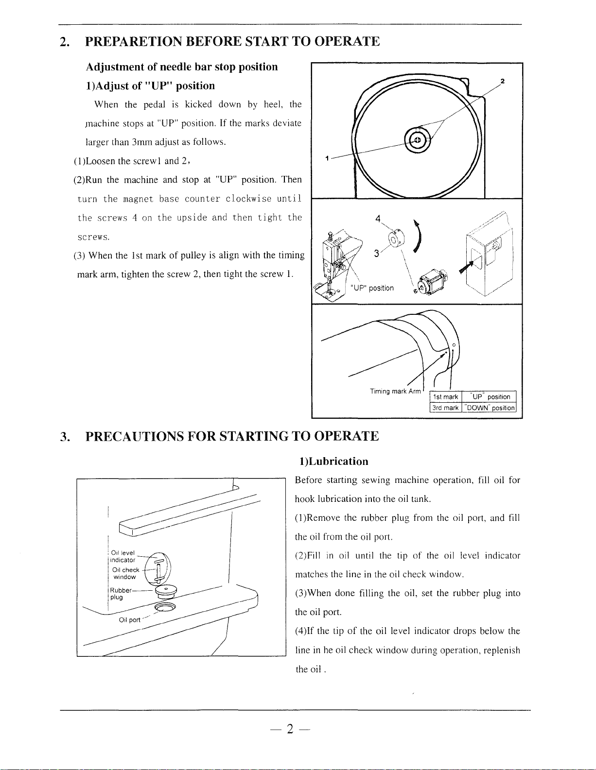
PREPARETION BEFORE START TO OPERATE
Adjustment
l)Adjust
When
JTiachine stops at "UP" position. If the marks deviate
larger than
(I
)Loosen the screw 1 and
(2)Run
turn
the
screws.
(3)
mark arm, tighten the screw
the
the
screws
When
the 1st mark
of
needle bar stop position
of
"UP" position
the pedal is
3mm
adjust as follows.
machine
magnet
4 on
and
base
the
kicked
2,
stop at "UP" position.
counter
upside
of
pulley is align with the timing
down
and
2, then tight the screw
by heel, the
clockwise
then
tight
2
Then
until
the
1.
3. PRECAUTIONS FOR STARTING
I~
I
TO
OPERATE
!)Lubrication
Before
hook
(1
the oil from the oil port.
(2)Fill
matches the line in the oil
(3)When
the oil port.
( 4
line in he oil
the
starting
lubrication into the oil tank.
)Remove
in
)If
the tip
oil.
sewing
the
rubber
oil until the tip
done
filling the oil, set the
of
the oil level indicator
check
window
''up"' position
"'oowN"'
position
machine operation, fill oil for
plug from the oil port, and fill
of
the oil level indicator
check
window.
rubber
drops
during operation, replenish
plug into
below the
-2-
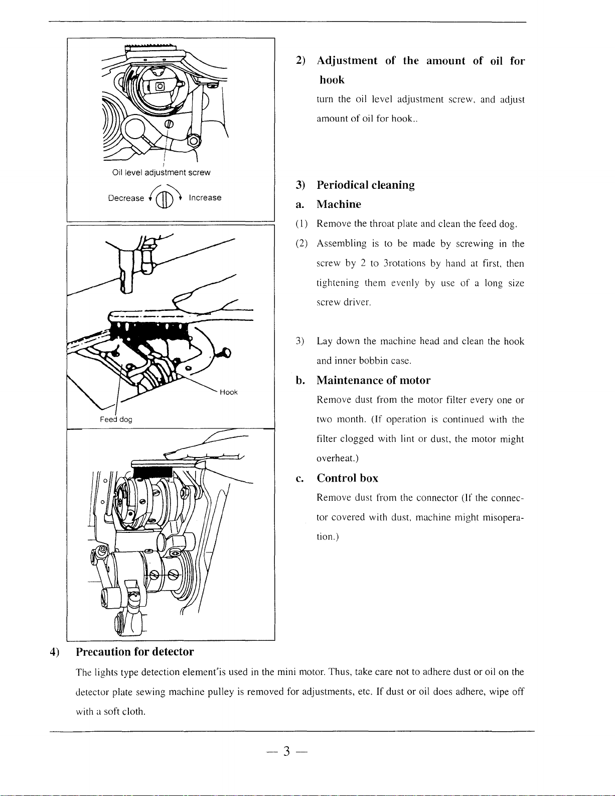
2)
Adjustment
of
the amount
of
hook
turn the oil level adjustment screw, and adjust
oil for
Oil level adjustment screw
Decrease (
I
CJI))
Increase
amount
3)
Periodical cleaning
a.
Machine
(
1)
Remove the throat plate and clean the feed dog.
(2) Assembling
screw by 2 to 3rotations by hand at first, then
tightening them evenly by use
screw driver.
3) Lay
and inner bobbin case.
b.
Maintenance
Remove dust from the motor filter every one or
of
oil for
hook
..
is
to be made by screwing
of
down
the machine head and clean the hook
of
motor
a long size
in
the
4)
Precaution for detector
The lights type detection
detector plate sewing machine pulley
element'is
two month.
filter clogged with lint or dust, the motor might
overheat.)
c.
Control box
Remove dust from the connector (If the connector covered with dust, machine might misoperation.)
used in the mini motor. Thus, take care not to adhere dust or oil on the
is
removed for adjustments, etc.
(If
operation
If
dust
is
continued with the
or
oil does adhere, wipe off
a soft cloth.
with
-3-
4.
HOW
TO
USE
THE
MACHINE
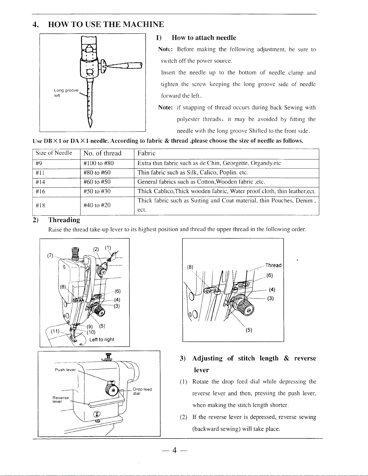
1)
How to
attach
needle
Noh:: Before making the following adjustment, be sure
switch
off
Insert the needle up to the bottom
Long
left
groove
tighten the screw keeping the long groove side
forward the left.
Note: if snapping
polyester
needle with the long groove Shifted to the front side.
Use
DB
X l
or
DA X 1 needle.
Size
of
Needle
#9
#11
#14
#16
#18
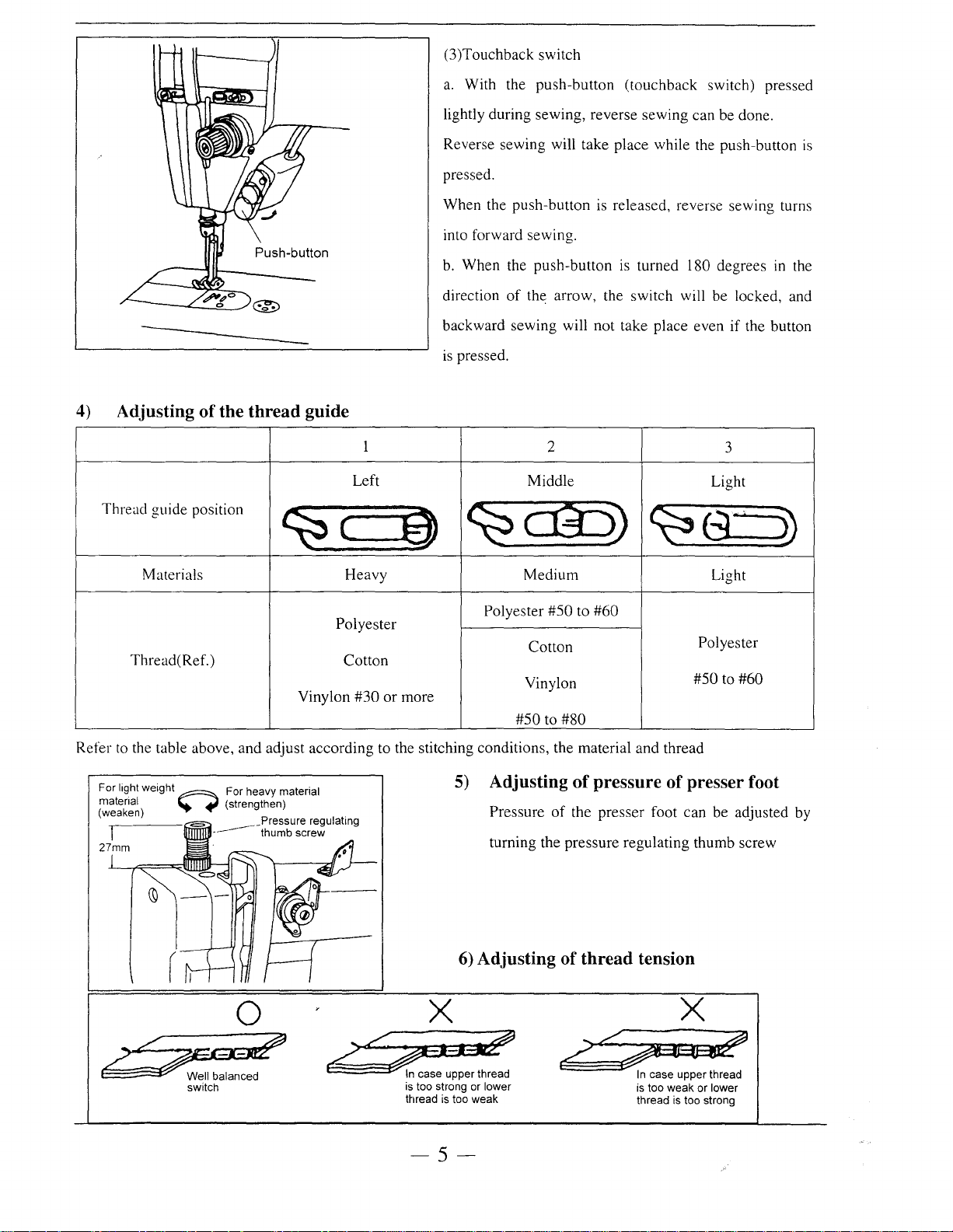
2)
Threading
Raise the thread take-up lever to its highest position and thread the
No.
#100
#80
#60
#50
#40
of
to
to
to
to
to
#60
#50
#30
#20
thread
According
#80
to
fabric & thread
Fabric
Extra thin fabric such as de Chin, Georgette, Organdy.etc
Thin
fabric such as Silk, Calico, Poplin. etc.
General fabrics such as Cotton,Wooden fabric ,etc.
Thick
Cablico,Thick wooden fabric, Water
Thick
fabric such as Suiting and
ect.
the
power
source.
of
thread occurs during back Sewing with
threads,
,please choose
upper
of
needle clamp and
it
may be avoided by fitting the
the
size
of
needle
proof
Coat
material, thin Pouches, Denim ,
thread
in
the following order.
as
follows.
cloth, thin leather,ect.
of
to
needle
/Thread
_
(8)
3)
Adjusting
ff£6.~1----(3)
of
_....-,-
- (4)
(5)
stitch length & reverse
lever
(I)
Rotate the drop feed dial while depressing the
reverse lever and then, pressing the push lever,
when making the stitch length shorter.
If
(2)
the reverse lever is depressed, reverse sewing
(backward sewing) will take place.
-4
(3)Touchback switch
a.
With the push-button (touchback switch) pressed
lightly during sewing, reverse sewing can be done.
4)
Adjusting
Thread guide position
Materials Heavy Medium
of
the thread guide
~
Reverse sewing will take place while the push-button
pressed.
When the push-button is released, reverse sewing turns
into forward sewing.
b.
When the push-button
direction
backward sewing will not take place even
is pressed.
1
Left Middle
c
of
the arrow, the switch will be locked, and
~c@S)
~
is
is
turned 180 degrees
2
3
Light
~s
Light
if
the button
in
the
~
Thread( Ref.)
Refer
to
the table above, and adjust according to the stitching conditions, the material and thread
~~
switch
0
Polyester
Vinylon
/~~
~
Cotton
#30
~
or
more
X
·
In
case upper thread
is too strong or
thread
5)
6)
is
too weak
Polyester
Adjusting
Pressure
turning the pressure regulating thumb screw
Adjusting
Cotton
Vinylon
#50
to
#50
to
#60
Polyester
#50 to
#60
#80
of
pressure
of
the presser foot can be adjusted by
of
thread tension
of
presser foot
X
;;q;
6'~
lower
In
case upper thread
is too weak or
thread is too strong
lower
-5-
Thread
tension nut
of
7)Adjusting
(I)
Upper thread tension can be adjusted by thread
tension nut.
(2)Upper thread
upper thread tension
is
to
be adjusted according to the
Strengthen
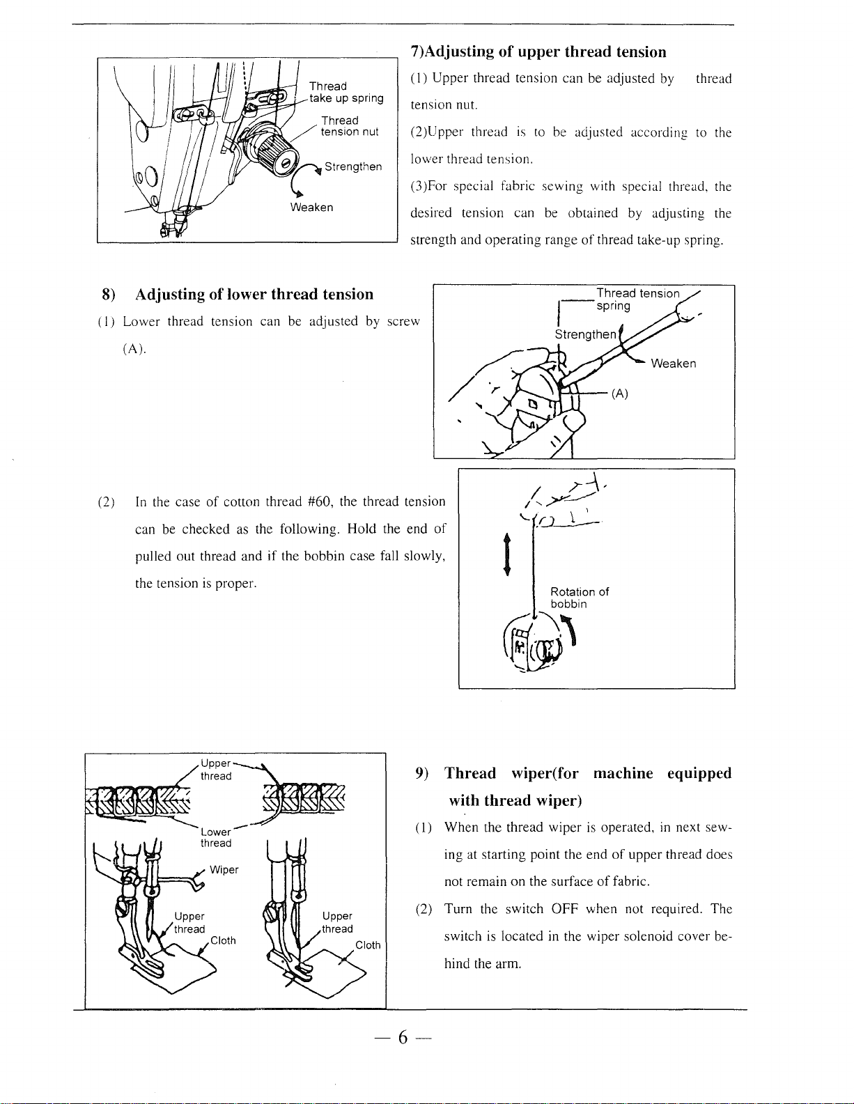
8)
Adjusting of lower thread tension
(I)
Lower thread tension can be adjusted by screw
(A).
(2)
In
the case
can be checked as the following. Hold the end
pulled out thread and
the tension
of
cotton thread #60, the thread tension
if
the bobbin case fall slowly,
is
proper.
lower thread tension.
(3)For special fabric sewing with special thread, the
desired tension can be obtained by adjusting the
strength and operating range
of
of
thread take-up spring.
Thread tension
,--spring
Strengthen
1
Rotation of
bobbin
Upper~
thread
, -{
Lower-
thread
9)
Thread wiper(for machine equipped
with thread wiper)
(
1)
When the thread wiper
ing at starting point the end
not remain
(2) Turn the switch
switch is located in the wiper solenoid cover behind the arm.
6-
~~
is
operated,
of
upper
on
the surface
OFF
of
fabric.
when not required. The
in
next sew-
thread does
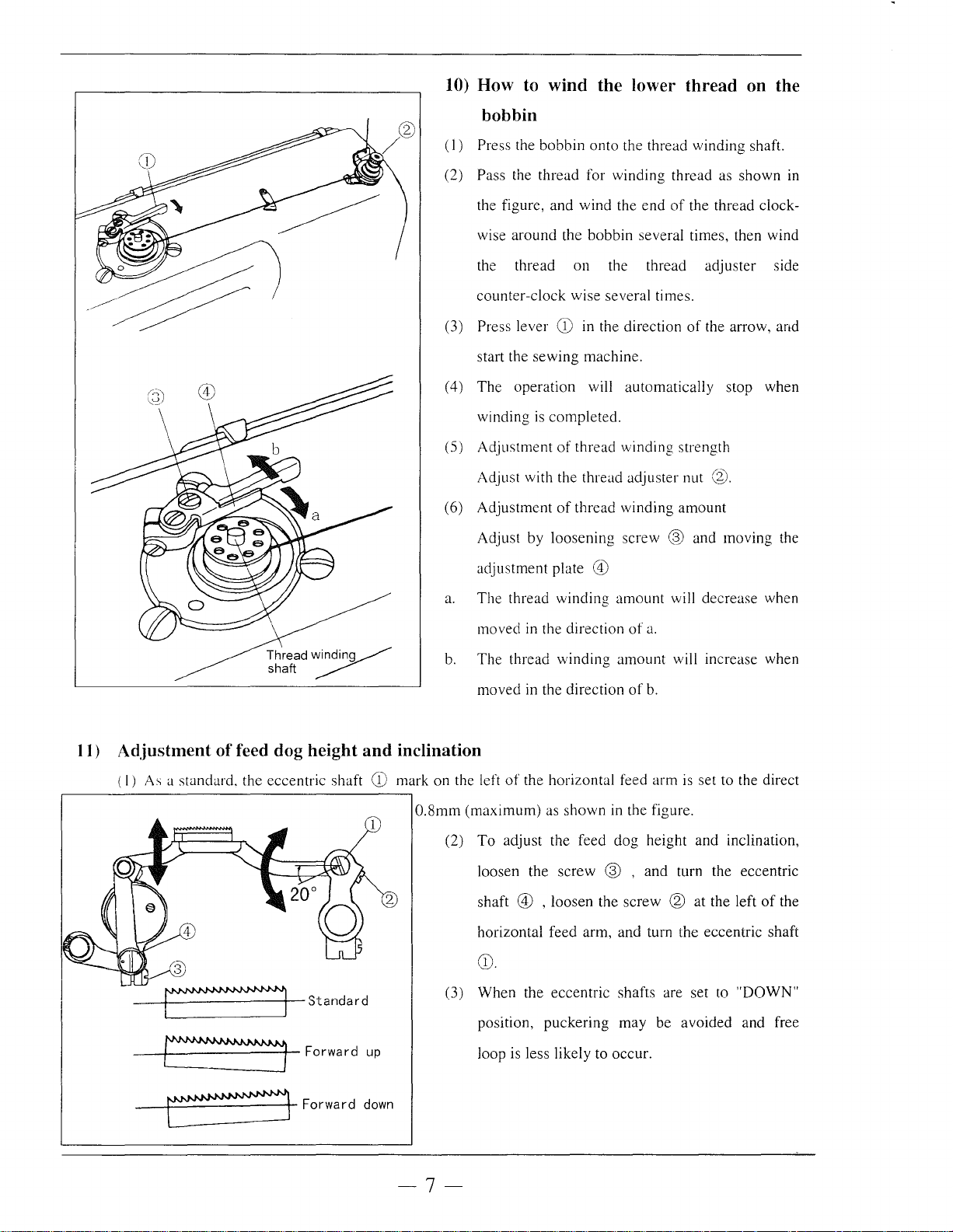
10) How to wind the lower thread on the
bobbin
(I)
Press the bobbin
onto
the thread winding shaft.
Pass the thread for winding thread as shown
(2)
the figure, and
wise around the bobbin several times, then wind
the thread
counter-clock wise several times.
Press lever
(3)
start the
( 4)
The
operation will automatically stop when
winding
(5)
Adjustment
Adjust with the thread adjuster nut
(6)
Adjustment
Adjust
adjustment plate
a.
The
by
thread
wind
the
on
the thread adjuster side
CD
in the direction
sewing
is
machine.
completed.
of
thread winding strength
of
thread
loosening
winding
screw ® and moving the
@)
winding
amount
end
of
the thread clock-
of
the arrow, and
®.
amount
will decrease when
in
11) Adjustment
(I)
As a standard. the eccentric shaft
~
Thread
winding~
shaft
of
feed dog height and inclination
~
Forwardup
CD
mark on the left
0.8mm
moved in the direction
b.
The
thread
moved
of
(maximum)
(2)
To
adjust the feed dog height and inclination,
loosen the
shaft
horizontal feed arm, and turn the eccentric
winding
in the direction
the horizontal feed arm
as
shown
screw
@)
, loosen the screw @ at the left
of
a.
amount
in the figure.
will increase when
of
b.
is
® , and turn the eccentric
CD.
(3)
When
position,
loop is less likely to occur.
the eccentric shafts are set to
puckering
may be avoided and free
set to the direct
of
the
shafi
"DOWN"
C9
Forward
down
-7-
( 4) When the eccentric shafts are set to "UP" posi-
of
tion, misalignment
cur and yarn severance may be avoided.
fabrics is less likely to oc-
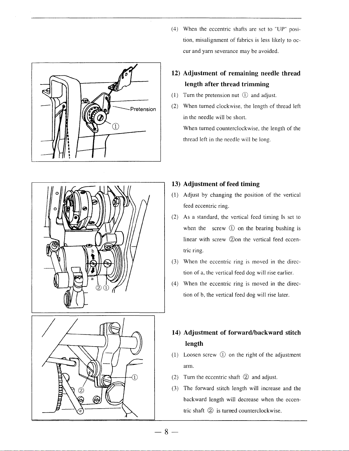
12) Adjustment
of
remaining needle thread
length after thread trimming
(I)
Turn the pretension nut
(2) When turned clockwise, the length
in
the needle will be short.
When turned counterclockwise, the length
thread left in the needle will be long.
13) Adjustment
(1) Adjust by changing the position
feed eccentric ring.
(2) As a standard, the vertical feed timing
when the screw
of
CD
and adjust.
of
feed timing
of
the vertical
CD
on the bearing bushing is
thread left
of
the
Is
set to
I
@on
linear with screw
tric ring.
(3) When the eccentric ring
tion
of
a, the vertical feed dog will rise earlier.
(4) When the eccentric ring
tion
of
b, the vertical feed dog will rise later.
14) Adjustment
of
the vertical feed eccen-
is
is
moved
moved
in
the direc-
in
the direc-
forward/backward stitch
length
(1) Loosen screw
arm.
(2) Turn the eccentric shaft
(3) The forward stitch length will increase and the
backward length will decrease when the eccen-
CD
on the right
of
the adjustment
@ and adjust.
tric shaft @ is turned counterclockwise.
-8-
( 4)
The
forward stitch length will decrease and the
Drive arm
Dimension A
-++1~-
(Blade section) /
0.3mm(standard)
Kmfe(left)
/
0
backward
shaft
length will increase when the eccentric
@
is
turned clockwise.
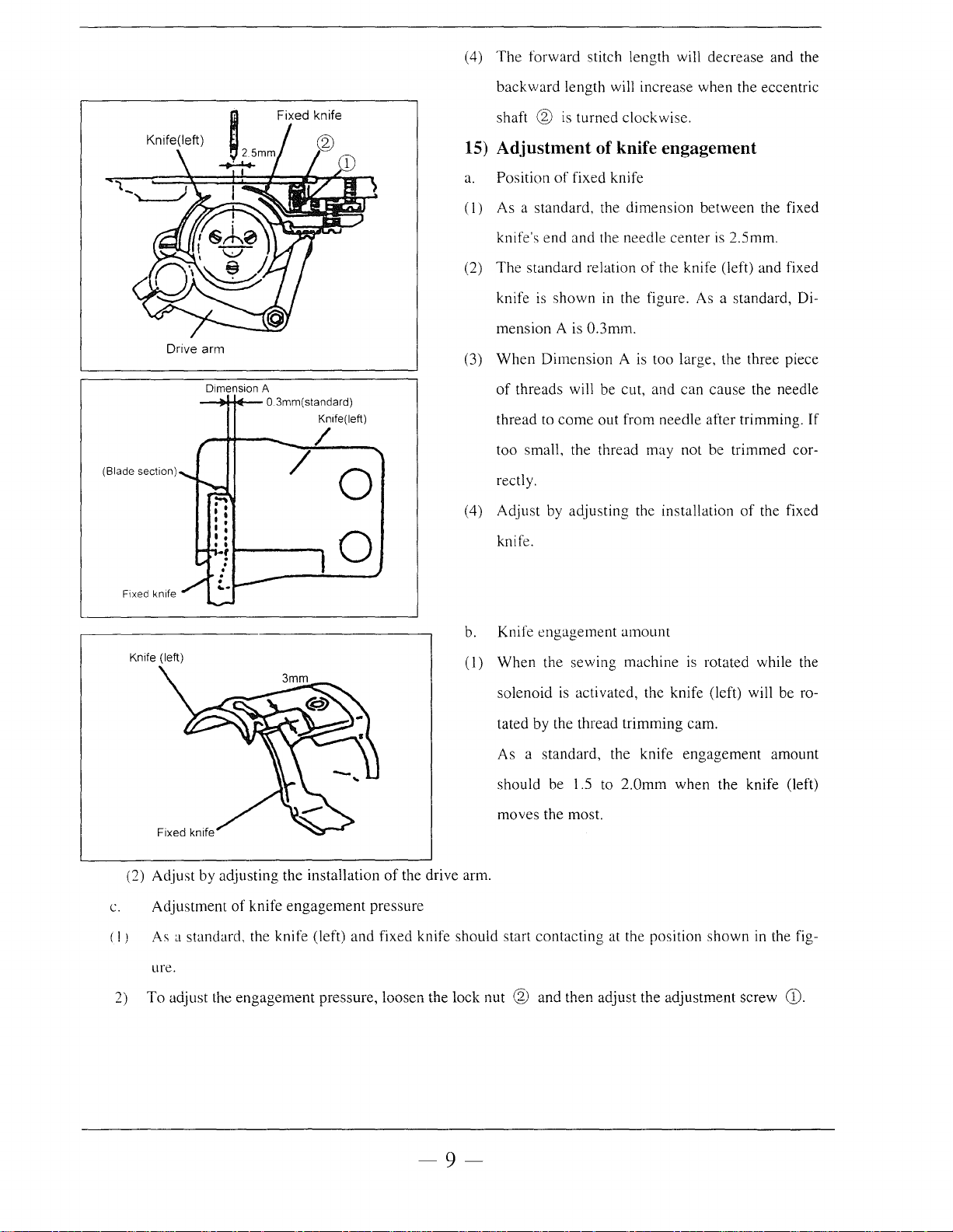
15) Adjustment of knife engagement
a.
Position
(I)
As a standard, the dimension between the fixed
knife's end
(2)
The
knife
mension A is 0.3mm.
When
(3)
of
thread to
too small, the thread
rectly.
( 4) Adjust by adjusting the installation
of
fixed knife
and
the needle center
standard relation
is
shown
Dimension
threads will be cut, and can cause the needle
come
of
the knife (left) and fixed
in
the figure. As a standard, Di-
A is too large, the three piece
out from needle after trimming. If
may not be trimmed cor-
is
2.5mm.
of
the fixed
Fixed knife
(left)
Knife
(2) Adjust by adjusting the installation
c.
Adjustment
( ! ) As a standard, the knife (left)
ure.
of
knife
engagement
knife.
0
b. Knife
(I)
of
the drive arm.
pressure
and
fixed knife should start contacting at the position shown in the fig-
engagement
When
solenoid
tated by the thread trimming cam.
As a standard, the knife engagement amount
should be 1.5 to
moves the most.
the sewing machine
is
amount
is
rotated while the
activated, the knife (left) will be ro-
2.0mm
when the knife (left)
2)
To
adjust the
engagement
pressure, loosen the lock nut @ and then adjust the adjustment screw
-9-
G).
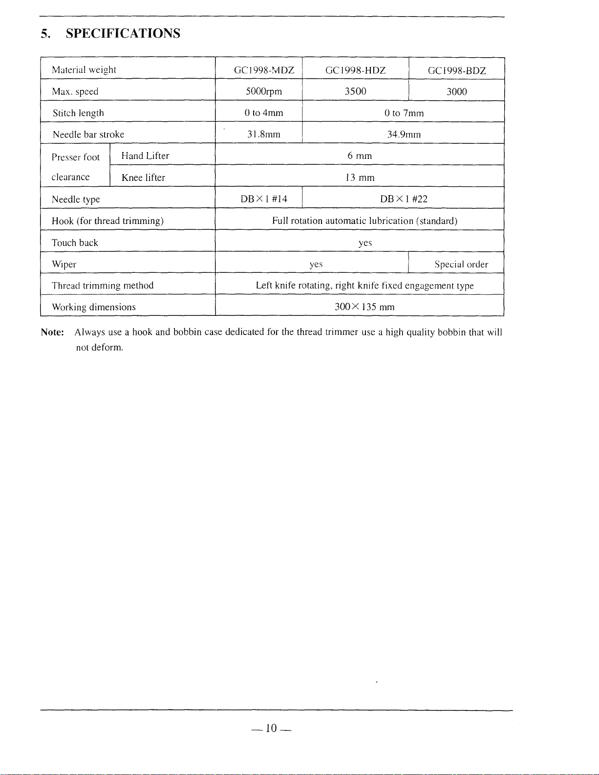
5.
SPECIFICATIONS
Material weight
Max. speed
Stitch length
Needle bar stroke
Presser foot
clearance
Needle type
Hook (for thread trimming)
Touch back
Wiper
Thread trimming method
Working dimensions
Hand Lifter
Knee lifter
Note: Always use a hook and bobbin
not deform.
GC1998-MDZ
5000rpm
0 to
4mm
31.8mm
DBX1#14
Full rotation
Left knife rotating, right knife fixed
case
dedicated for the thread
GC1998-HDZ
3500
13
automatic
yes
300X
trimmer
GC1998-BDZ
3000
0 to
7mm
34.9mm
6mm
mm
DBX 1 #22
lubrication (standard)
yes
Special order
engagement
135 mm
use a high quality bobbin that will
type
-10-
 Loading...