

Page 1
Purchasing Dept
111
1 _c:
®
HIGHLEAD
GC1088 Series
Hig Speed Sing Needle
Industrial
Sewing
Machine
..
Y llllllallli..
Lockstitch
INSTRUCTION MANUAL
Page 2
BEFORE
l.
Never
with
2.
After
rotation.
the
the
as
3.
Do
4.
Confirm
are
the
OPERATION
operate
oil.
setting
needle
handwheel. (
observed from
not
use a
that
correct
motor nameplate.
the
up
To
check
down,
larger
the
by
checking them
machine
the
it,
and
The
the
voltage
unless
machine,check
turn
turn
the
handwheel should
handwheel
motor
pulley
and phase (
its
oil
the
the
handwheel
power switch
turn
side.)
for
against
pan has been
direction
by
hand
ON
while
observing
counterclockwise
the
first
single
the
ratings
one
or
3-phase)
filled
of
motor
to
bring
month.
shown
on
OPERATION
l.
Keep
your hands
switch
2.
Do
not
the
machine
3.
Be
sure
machine head
4.
When
an
off
the
5.
During
person'
belt,
bobbin winder
close
6.
If
or
any
7.
Don' t
to
your machine
any
of
PRECAUTIONS
ON
or
while
put your
is
to
turn
or
operator
power.
operation,
s head
them.
other
them
clean
protectors,
removed.
the
away
from
the
fingers
operating.
the
power
removing
leaves
be
careful
or
hands
or
Doing
is
provided
face
so
the
needle
machine
into
the
switch
the V belt.
from
the
not
to
come
motor. Also,do
maybe
with a belt
do
not
of
machine head
1
when
is
operating.
thread
OFF
machine,make
to
allow your
close
dangerous.
operate
you
turn
take-up
before
to
not
cover,
your machine
with
cover while
tilting
sure
or
the
handwheel, V
place
finger
thinner.
the
power
the
to
turn
any
other
anything
guard
with
Page 3
1.
INSTALLATION
*
Installing
1)
The
oil
table
2)
nails®
side
@
3)
the
machine head
Fig. 4 )
groove.
Fix
two
B ( hinged
on
the
Fix hinge
machine head
pan should
rubber
as
illustrated
fixed
CD
into
on
the
seats
® ®
(Fig.
oil
pan
rest
on
CD
on
above. Fix
side)
seats.
to
cushions @
the
table
using
( Fig.
opening
rubber
l,Fig.2,Fig.3,Fig.4)
the
four
side
nails®·
1,
on
corners
A (
operator' s side)
two
Fig. 2 )
in
the
hinge ®
the
four
of
the
machine
cushion
Then
machine bed, and
before
corners.
seats@
place
placing
oil
( Fig. 3 ,
(i
using
on
pan
fit
the
Fig.I
CD
@
CD
G)
-~.-~
Fig.2
--~-----·
@
I
...
~
2
j
®
CD
18.5mm
\.
\~)
Iii
Page 4
®
>"---~
Fig.3
Fig.4
@
@
>~
@
CD
3
Page 5
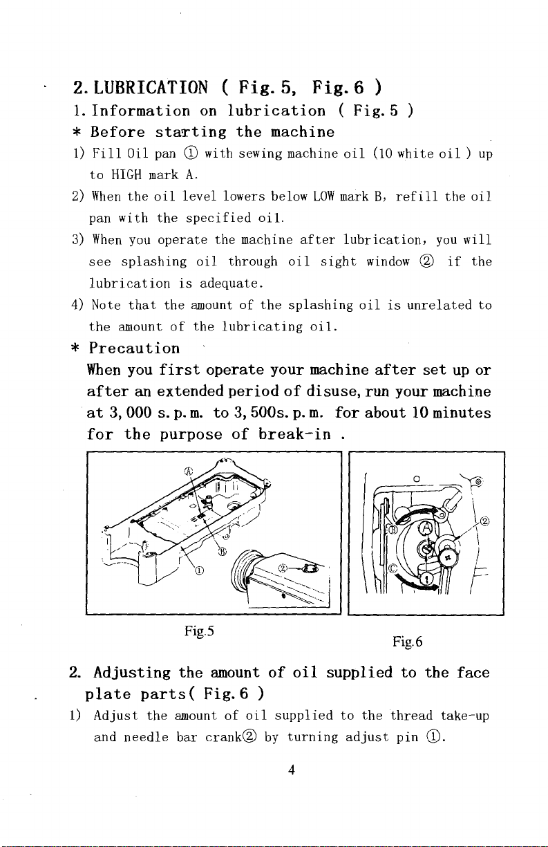
2.LUBRICATION ( Fig.5,
1.
Information
*
Before
1)
Fill
Oil
to
HIGH
2)
When
the
pan
with
3)
When
you
see
splashing
lubrication
4)
Note
that
the
amount
*
Precaution
When
you
after
at
for
an
3, 000 s.
the
staTting
pan
mark
oil
the
operate
extended
on
CD
with sewing machine
A.
level
specified
oil
is
adequate.
the
amount
of
the
first
operate your machine
p.
m.
to
purpose
lubrication
the
machine
lowers below
oil.
the machine
through
of
the
lubricating
period
3,
of
of
500s.
break-in.
Fig.6)
(
oil
LOW
mark
after
oil
splashing
p.
lubrication,
sight
oi
1.
disuse,
m.
for
Fig.5)
(10
B,
window
oil
is
after
run
about
white
refill
oil)
the
you
@
if
unrelated
set
up
up
oil
will
the
to
or
your machine
10
minutes
2.
Adjusting
plate
1)
Adjust
and
parts(
the
needle
Fig.5
the
Fig.6)
amount
bar
crank@
amount
of
oil
of
oil
supplied
by
turning
4
supplied
to
adjust
the
Fig.6
to
thread
pin
the
take-up
CD.
face
Page 6
2) The minimum amount
brought
pin
3) The
brought
crank
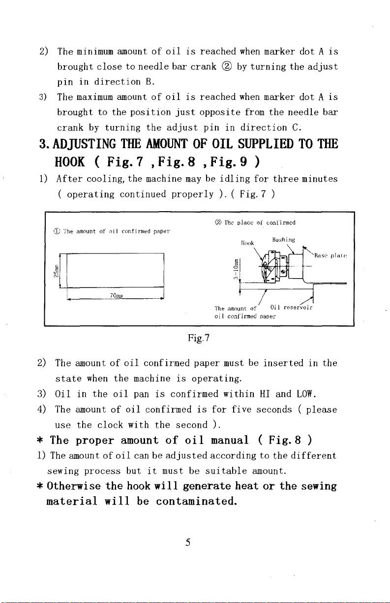
3.
ADJUSTING
close
in
direction
maximum
to
by
turning
to
amount
the
position
THE
needle
of
oil
is
reached
bar
crank
B.
of
oil
is
reached
just
opposite
the
adjust
AMOUNT
OF
pin
OIL
when
marker
® by
turning
when
marker
from
in
direction
SUPPLIED
the
dot A is
the
adjust
dot A is
needle
C.
TO
bar
THE
HOOK ( Fig.7
1)
After
Cf;
2) The amount
state
3)
Oil
4) The amount
use
*
The
1) The amount
sewing
cooling,
(
operating
The amount
in
the
of
when
the
clock
oi I cnnfi
of
the
oil
of
proper amount
of
oil
process
* Otherwise the
material
will
,Fig.8
the
machine
continued
rmed
pnper
oil
confirmed
machine
pan
is
oil
confirmed
with
the
can be
but
it
hook
will
be contaminated.
may
properly
Fig.7
paper
is
operating.
confirmed
is
second).
of
oil
adjusted
must
be
generate heat or the sewing
,Fig.9)
be
idling
). ( Fig.
(2)
The
place
Hnok
The amount
oil
confirmed
must
within
for
five
manual (
according
suitable
for
three
minutes
7 )
of
conrirmcd
Hushing
'Rr1s1"~
of
Oil
re:servoir
paper
be
inserted
HI
and
seconds ( please
in
LOW.
Fig.8)
to
the
different
amount.
plat<:
the
5
Page 7
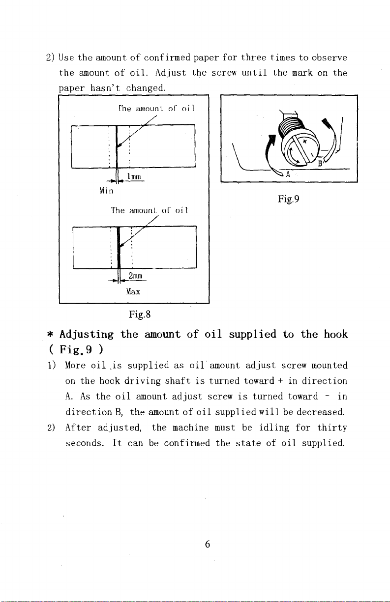
2) Use
the
paper
the
amount
amount
hasn't
Min
of
confirmed
of
oil.
changed.
fhe
amounl
1mm
The amounl
Max
Fig.8
Adjust
of
of
oil
oil
paper
the
for
screw
three
until
times
the
Fig.9
to
observe
mark on
the
* Adjusting
(
Fig.9)
1) More
on
the
A.
As
direction
2)
After
seconds.
oil
is
hook
the
oil
B,
adjusted,
It
the
amount
supplied
driving
amount
the
can
of
as
oil
shaft
amount
the
be
confirmed
is
adjust
of
oil
machine must be
oil
supplied to the
amount
turned
screw
supplied
the
6
adjust
toward+
is
turned
state
will
idling
of
screw
in
direction
toward -
be
decreased.
for
oil
supplied.
hook
mounted
in
thirty
Page 8

4.ATTACHING
*
Turn
the
the
needle.
A
needle
size
material
1)
Turn
point
2) Loosen
A
3)
Insert
will
4)
Securely
5) Check
to
of
according
the
of
screw
facing
the
go on
that
the
left
used.
handwheel
THE
motor power
DBX 1 14
to
its
stroke.
@, and
exactly
needle
further.
tighten
long
in
NEEDLE
#
should
the
count
until
hold
to
the
in
the
screw
groove C
direction
OFF
before
be used.
the
needle
needle
right
direction
@.
of
D.
(Fig.IO)
starting
Select a proper
of
thread
bar
CD
with
in
direction
of
the
needle
-@
and
reaches
its
the
arrow
is
facing
to
attach
the
type
the
highest
indented
B.
until
exactly
needle
of
part
it
®
.......::___~--
__
.----
©
Fig.to
7
Page 9

5.
SETTING
(
Fig.
1)
Hold
directed
bobbin
2)
Pass
in
direction
tension
3) Cheek
when
THE
11
)
the
bobbin
to
the
into
the
the
thread
B.
spring
that
the
bobbin
thread C is
BOBBIN
in a way
left
as
bobbin
through
By
so
doing,
and
come
rotates
pulled.
INTO
that
observed
case.
thread
the
out
slit
thread
from
in
the
THE
the
thread
from you,
A,
and
will
notch
direction
BOBBIN
open end
and
set
pull
the
pass
under
B.
of
the
CASE
is
the
thread
the
arrow
Fig.11
8
Page 10

6.
THREADING THE MACHINE HEAD( Fig.12 )
Fig.12
7.ADJUSTING
1)
Turn
stitch
and
align
arm.
2) The
3)
dial
When
you want
length
direction
dial
THE
length
the
desired
calibration
to
CD
of
the
STITCH
dial
CD
number
is
decrease
while
arrow.
pressing
LENGTH
in
the
to
marker
in
millimeters.
the
stitch
direction
dot
length,
feed
lever
( Fig.
of
the
A on
the
turn
@
13)
arrow,
machine
stitch
in
the
9
Page 11

8.THREAD
TENSION
I.adjusting
1) Adjust
CD
2)
As
thread
3)
As
the
the
according
you
turn
tension
you
turn
tension
2.Adjusting
1)
As
you
turn
direction C ),
2)
As
you
turn
The
bobbin
( Fig.
the
needle
needle
nut
screw ® counterclockwise (
thread
to
CD
will
nut
will
the
tension
the
thread
the
sewing
clockwise (
increase.
CD
counterclockwise
decrease.
bobbin
adjust
bobbin
tension
14)
thread
tension
specifications.
thread
thread
will
tension
using
in
direction
tension
screw ® clockwise (
tension
decrease.
tension
(indirection
in
adjust
A),
the needle
will
increase.
direction
nut
B ),
in
D ) ,
10
Fig.14
\ \
\
''{_
'\
Page 12

9.THREAD
1.
Changing
1) Loosen
2)
As
you
the
3)
As
you
the
2. Changing
1) Loosen
2) Loosen
3)
As
you
the
4)
As
you
the
TAKE-UP
setscrew
turn
stroke
turn
stroke
the
setscrew
setscrew@,
turn
pressure
turn
pressure
the
stroke
tension
of
the
the
will
pressure
tension
will
the
post
will
SPRING
of
( Fig.
thread
®·
post @ clockwise ( in
thread
knob
be
®,
take-up
counterclockwise ( in
decreased.
of
and
take
and
remove
post
@
be
increased.
counterclockwise ( in
be
decreased.
spring
thread
out
tension
clockwise ( in
take-up
will
take-up
tension
15)
spring
direction
be
direction
spring
asm. ®·
post@.
direction
direction
® @
CD:
A ) ,
increased.
B ) ,
CD:
A ) ,
B),
CD
Fig.15
IO.HAND
1)
To
lifter
2) The
3) The
hand
LIFTER
stop
CD
presser
presser
lifter
the
in
machine
direction
foot
foot
will
CD
is
(Fig.
with
will
go
turned
16)
A.
go up
back
down
11
its
presserfoot
about
to
its
original
in
direction
5.5mm
up,
and
stop.
position
B.
turn
hand
when
Page 13

4)
Using
foot
Fig.16
the
lift
knee
of
about
lifter
10mm
, you can
and a maximum
get
the
lift
standard
of
about
presser
13mm.
11.PRESSER
1) Loosen
clockwise
be
2)
As
(
decreased.
3)
After
4)
For
spring
GC1088-H
nut
increased.
you
turn
in
direction
adjustment,
general
regulator
@.
(indirection
the
it
FOOT
fabrics,
is
PRESSURE
As
you
presser
B
),
tighten
is
7kg.)
turn
spring
the
the
29
presser
A),
the
presser
nut
standard
to
( Fig.
spring
presser
regulator
foot
17)
foot
counterclockwise
pressure
@.
height
32mm(5kg). (For
of
regulator
pressure
will
the
presser
the
..
---
-
CD
will
be
model
Fig.17
12
Page 14

12.ADJUSTING
1)
Loosen two
properly
setscrews.
2)
To
obtain
dropping
dog
with
the
throat
3)
To
advance
material
of
the
4)
To
delay
tightness,move
direction
*
If
moving
will
setscrews
position
the
standard
from
the
the
top
plate.
the
feed,
move
arrow.
the
feed
from
the feed
be break .
CD
THE
® and ® on
the
throat
of
the
feed
the
timing
the
feed
the
arrow.
eccentric
FEED
timing
feed
TIMING ( Fig.18)
eccentric
feed
timing,when
plate , align
hole
on
in
eccentric
in
eccentric
cam.
the
order
order
cam
feed
Then
needle
cam
to
cam
to
eccentric
retighten
the
the
top
and
to
prevent
in
the
increase
in
the
far,the
Standard
cam
feed
of
the
the
direction
opposite
needle
CD,
the
dog
is
feed
top
of
uneven
stitch
Fig.18
13
Page 15

13.HEIGHT
1)
The
feed
dog
the
throat
GC1088-A,
GC1088-H,0.95mm
2)
If
the
sewing
0.
7mm
3)
To
adjust
(1) Loosen
(2)
(3)
*
Precaution
If
the
be
abraded
it
feed
light-weight
to
0.8mm)
Move
the
Securely
screw
OF
THE
is
factory-adjusted
plate
juts
to
dog
juts
out
the
height
screw®
feed
bar
tighten
is
tighten
.
a. Feed dog
FEED
surface
out
1.05mm.
too
much,
materials
of
the
of
crank
up
or
screw®·
too
DOG
so
0.8mm
0.
7mm
puckering
. (
Recommended
feed
dog:
CD.
down
to
securely,
b.
Throat
( Fig.
that
it
to
0.9mm.For
to
0.8mm.For
may
make
the
plate
19)
juts
out
from
the
the
result
protrusion:
adjustment.
crank
when
will
CC1088-M
0.
75-0.85mm
~~,;;-
b
GC1088-A
702J~~
GC1088-H
702Jr~~~
Fig.19
14
o.
7-0.Smm
b
0.95-1.
b
05mm
Page 16

14.
NEEDLE-TO-HOOK
RELATIONSHIP ( Fig.
1.Adjust the timing between
as
follows:
1) Turn
*
Adjusting
2)
the
lowest
When
needle
bushing@,
When
it,
point
using
bar®
using
then
handwheel
of
the
needle
the
with
then
the
needle
tighten
to
its
stroke,and
bar
needle
the
tighten
setscrew
bring
height"
of
DB X 1,
bottom
setscrew(!).
of
DAX
(!).
the
the
1,
align
needle
needle
loosen
align
end
of
and
bar
setscrew(!).
marker
needle
marker
~®
20 )
the
hook
down
to
the
line
A on
bar
lower
line B with
©
®
*
Adjusting
When
3)
setscrews,
the
bushing
line D with
using
needle
@.
Fig.20
position
the
needle
turn
the
bar ® with
When
using
the
bottom
of
the
hook
of
handwheel,
the
the
end
of
15
DB X 1,
and
bottom
needle
needle
loosen
align
end
of
of
DAX
bar
,'.
-~---®
' \
' . '
' '
\ 0 }
' ,
' ,
...
___
.....
0
the
three
marker
needle
1,
align
lower
bushing
',
line
bar
hook
Bon
lower
marker
@.
Page 17

4)
After
making
align
Provide a clearance
and
*
Precaution
If
will
hook
the
hoo~
the
clearance
be abraded.
over.
* Note
that
the
replacing
very
machine
type
of
the
blade
then
type
the
hook,
of
original
adjustments
point®
of
0.04mm
securely,
is
too
If
it
is
of
hook
shall
the hook
assemblage.
mentioned
with
the
to
0.
tighten
small,the
too
big,
to
be
substituted
be
in
installed
in
the
above
center
lIIlIIl.
the
it
between
hook
tip
will
of
needle@.
the
setscrews.
of
the
lead
needle
to
for,
conformity with
in
the
sewing
steps
hook
skip
when
the
15.ADJUSTING
(
Fig.
1)
2)
Loosen
the
angle
After
21 )
setscrew
adjustment,securely
of
THE
the
HEIGHT
CD,
and
adjust
presser
OF
the
foot.
tighten
16
THE
presser
the
CD
Fig.21
PRESSER
bar
height
setscrew.
BAR
and
Page 18

16.ADJ(JSTING
{
Fig.22)
1)
When
sewing
to
the
left
2)
3)
pulled
When
to
pulled
When
with
sewing
the
the
the
out
right
out
marker
center
THE
heavy-weight
in
direction A to
by
the
light-weight
in
direction B to
by
the
line
\
\
~\
Fig.22
thread
thread
of
't
\
\
THREAD
materials,move
take-up.
materials,move
take-up.
C on
the
the
screw,
•@
~-CD
increase
decrease
thread
it
is
®-
TAKE-UP
thread
the
length
thread
the
length
guide
standard.
CD
of
of
is
STROKE
guide
guide
CD
thread
CD
thread
aligned
17.
INSTALLING
WINDER
1.
Installing
1)
Drill
machine
2)
Insert
Install
3)
middle
4)
Install
5) Using
cover
{Fig.23,Fig.24,Fig.25)
four
table.
support
the
of
the
the
® on
screw
THE
Procudure
wooden
CD
front
the
the
hol~
back
belt
belt
@, @
support
BELT
screw
in
the
and
COVER
guide
tapped
cover®,
cover ® at C and
washer
the
tighting
17
holes
hole
get
® ,
AND
A,
B,
C and D
in
the
handwheel
fix
torque
THE
the
arm.
D.
the
front
for
BOBBIN
in
the
in
the
be 1 t
the
screw
Page 19

6)
7)
8)
@
is
Fix
the
Move
touches
0.
5-lmm,
Fix
bobbin
about
30
kgf • cm,
cover.
the
back
belt
the
front
fix
it
winder @ at A and B using
cover
belt
using
for
cover@,
the
the
screw®
®
wooden
backward
then
screws
is
move
the
about
until
and
wooden
25
kgf • cm.
its
further
washers.
47
rubber
more
screws.
Fig.23
©
©
\
63.5
75. 5
Unit:mm
®
Fig.24
18
Fig.25
Page 20

18.ADJUSTING
(
Fig.26,Fig.27)
1) The
2)
3)
standard
knee
lifter
You
can
lifter
GC1088-A
When
you have
be
sure
position
adjust
adjust
that
Fig.26
THE
height
is
10mm.
the
screw(D. ( The
type
)
adjusted
the
does
not
HEIGHT
of
presser
the
bottom
hit
the
presser
foot
presser
end
of
presser
OF
lift
max.
lift
foot
needle
foot@.
---<)
THE
foot
up
to
shoule
1 i
bar
KNEE
lifted
13mm
using
be
ft
to
over
®
in
its
LIFTER
using
9mm
10mm
lowest
the
knee
for
,
Fig.27
19
Page 21

19.SPECIFICATIONS
Application
Sewing speed
Stitch
Presser
length
foot
(by knee
Needle
Lubricating
lift
lifter)
oil
GC1088-M
For
medium-weight
materials
Max.
'Max.
10mm
13mm
#
5500s.
(standard)
DBX
9-18
p.m
5mm
(max)
1
#
GC1088-A
For For
light-weight
materials
Max.4000s.p.m
Max.
4mm
9mm
(max)
DAXl
# #
9-
11
10
white
oil
GC1088-H
heavy-weight
materials
Max.
3500s.p.m
Max.
5mm
10mm
(standard)
13mm
(max)
DBX
1
#
#
20-
23
20
 Loading...