

Page 1
Purchasing
Copy
Dept
HIGH
LEAD
GC0618-1/-SC/-D2/GC0518-1
Heavy Duty Compound Feed Lockstitch Sewing Machine
Instruction
Parts
SHANGHAI
HUIGONG
N0.3
Catalog
SEWING
Manual
MACHINE
FACTORY
Page 2

Page 3
1.
PRECAUTIONS
2.
MAlN SPECIFICATIONS
3.
PREPARATION AND LUBRICATION ..
4.
REPLACE
5.
WINDING
6.
WINDING
7.
REMOVING AND INSERTING
8.
THREADING........ . .......................
9.
REGULATING THE
10 ADJUSTMENT OF
ll.
ADJUSTING THE
12. STITCH LENGTH
13.
ADJUSTING
14.
RELATIVE POSITION OF THE FEED
15
THE POSITION OF
16.
TIMING THE
17
ADJUSTING THE
18. TIMING
19.
ADJUSTING THE
BETWEEN
BEFORE
NEEDLES
...
..
ADJUSTMENT
THREAD
THE
LIFT
ADJUSTMENTS
THE
HEIGHT
THE
NEEDLE
HEIGHT
THE
HEIGHT
STARTING OPERATION
................
......
PRESSURE
OF THE ALTERNATING
OF
NEEDLE
WITH FEED
OF THE
HOOK
OF THE
20. TIMING OF THE VIBRATING
21
ADJUSTMENT OF THE
CLEARANCE
COLLAR
22. ADJUSTING THE
23. ADJUSTMENT OF
24. ADJUSTMENT OF KNIFE
THREAD
NEEDLE
CONTROLLER
BAR STOP POSITION
ENGAGEMENT
CONTENTS
.
.
THE
BOBBIN
TENSIONS
ON
AND
THE
FEED
DOG
AND
THE
DOG
NEEDLE
AND
THE
PRESSER
PRESSER
BETWEEN
................
..................
.
.....
.
THE
MATERIAL.
PRESSER
REVERSING
DOG
....
TO
NEEDLE
NEEDLE
.......................
BAR
.....
NEEDLE
FEET
FOOT
..
FEED FORKED
SPRING
...
.
.
.
.............
FEET
LEVER
..
...........................
PLATE ... 7
HOLE OF THE
FEED
DOG
.....................
.
.....................
............................
CONNECTION
.....
.
AND FEED FORK
.
......................
..........
.
............
.
.
.....
.
.......
.
......
.
.....
.
........
.
........
.......
.
........
.....
. .. 6
. ... 7
.
...
.
2
2
.
.3
3
.4
.4
..4
5
5
. .6
6
. .6
8
..
10
7
8
8
9
9
9
9
~I~
Page 4
1.
PRECAUTIONS
1) Safety Precautions:
(
1)
When turning the power on, keep your hands and fingers away from the area around/under the needle
and the area around the balance wheel.
Power must
(2)
be
turned
BEFORE
off
when the machine
STARTING
is
not in use, or when the operator leaves the seat.
OPERATION
( 3) Power must
be
turned
off
when tilting the machine head, installing
or
removing the
"V"
belt, adjusting
the machine, or when replacing.
(4) Avoid placing fingers, hairs, bars etc., near the balance wheel,
"V"
belt,
bobbin
winder balance wheel,
or motor when the machine is in operation
(5) Do not insert fingers into the thread take-up cover, under/around the needle, or balance wheel when the
is
machine
(6)
If
a belt cover, finger guard, eye guard are installed, do not operate the machine without these safety
in operation.
devices.
2) Precautions before Starting Operation:
(I)
If
the machine's oil pan has an oil sump, never operate the machine before filling
(2)
If
the machine is lubricated by a drop oiler, never operate the machine before lubricating.
(3) When a new sewing machine is first turned on, verify the rotational direction
po\ver on. (The balance wheel should rotate counter-clockwise when viewed from the balance
the
it.
ofthe
balance wheel with
wheel)
(4)
Verify the voltage and (single or three) phase with those given
on
the machine nameplate.
3) Precautions for Operating Conditions:
(1) Avoid using the machine at abnormally high temperature (
J
lower
(2)
Avoid using the machine
2. MAIN
SPECIFICATIONS
Item
Max. Sewing Speed L000 rpm
f----------''---'-----t-------------------------------·-·-··-··
f---------=----t--------------------------------------------
1 Take-up Lever Stroke
t-------------+-------------------------·------------
Stitch Length 0 I 0
in
dusty conditions
r;coo
1
1-1
1 J
r;r
:oo
1
1-1
1
sr:
J
Needle Bar Stroke
t-H--'~:.c.~gh:.::dc..::~:...:~:...:~:._~:..c~c_;~c::.~vs:...:ee:.::~....:1F-'~=-=oac...:.ti_n-+---------L-:J-III_m
Presser foot
lift By Knee
f--------__[__--=----t------------~----=---------------·
Rotating Hook
Lubrication
By
Hand H
t---=------+----------------:-;-----------------
Needle
Motor
Double Capacity Hook
370W Clutch Motor
I Large Hook
I
3S"C
or
r;r:oo
11-1
111111
71.
;,
111111
:l::J
111111
_________
111111
l~111111
Ill'~
17
LL;::
for
Manual
Speed adj. Motor
higher)
1
IlL
L~;::
Trimmer
or low temperature (
S"C
l
-------·
------
-------·.
---------
l_l__-
___
-~~----~=---~--~-~~
·-----··-·
-·--·--
~-Do~;blc
1 370W Clutch Motor
C'~l]~;~~J~lo()_<
-----
-·
-·-
-----
or
---
--
-2-
Page 5
3.
PREPARATION AND LUBRICATION
1)
Cleaning the machine
Before leaving the factory, the machine parts are coated with rust-preventive grease, which may be
hardened and contaminated by dust during storage and shipment. This grease must be removed
gasoline.
2) Examination
Though every machine is confirmed by strict inspection and test before leaving the factory, the
machine parts may be loose or deformed after long distance transportation with jolt. A thorough
exammation must be performed after cleaning the machine. Turn the balance wheel to sec
running obstmction, parts collision, uneven resistance or abnormal noise.
made accordingly before nm-in operation.
If
these exist, adjustment niust
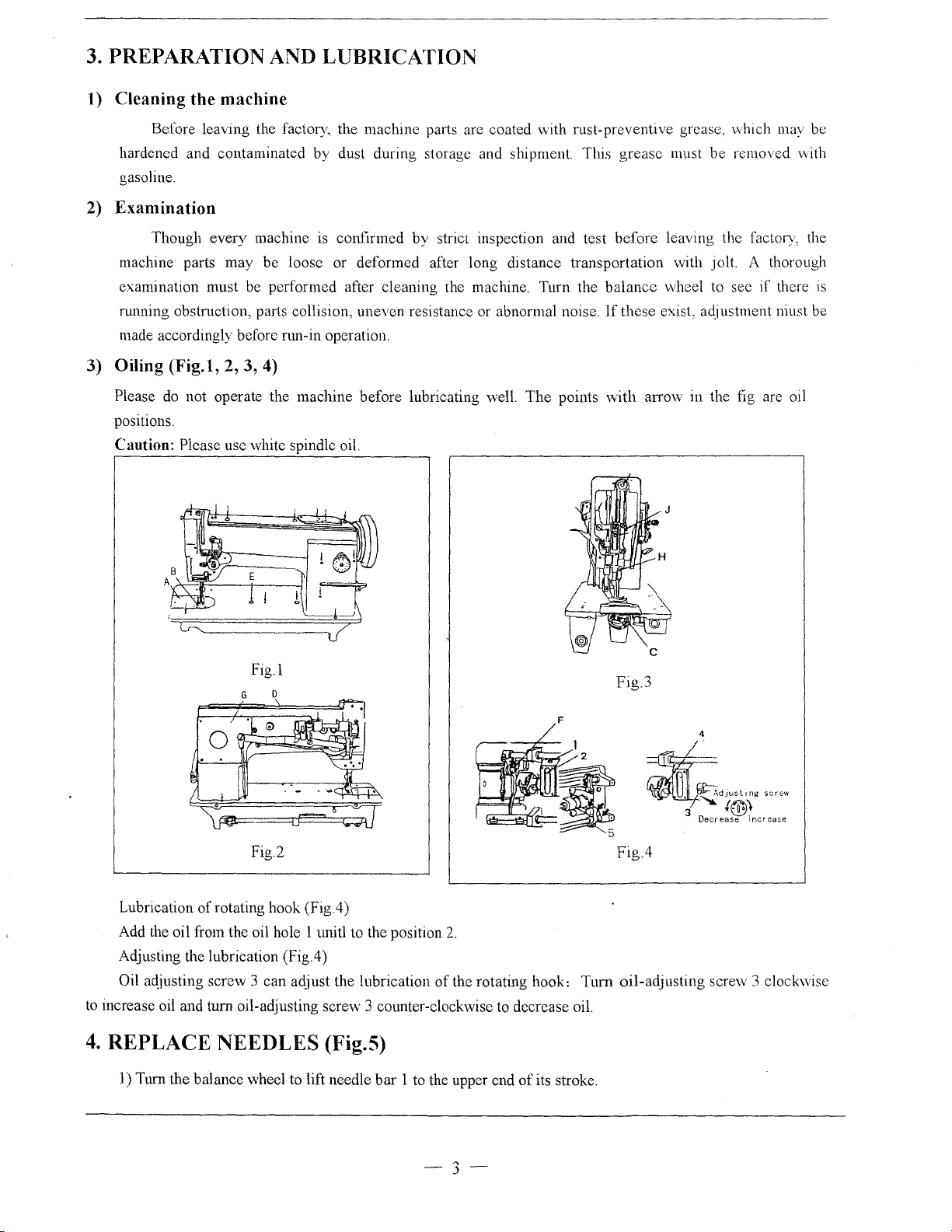
3) Oiling (Fig.l, 2, 3, 4)
if
vvith
there
is
be
Please
positions.
Caution: Please use white spindle oil.
do
not operate the machine before lubricating well. The points
Fig.l
with
arrO\v
in the fig are oil
Fig.3
F
~~"'""''"'
~
4
3
Decrease
,,,.
1~\
lncrea.s.e
Fig.2
Lubrication
Add the oil from the oil hole 1 1llitl to the position
Adjusting the lubrication (Fig.4)
Oil aqjusting screw 3 can aqjust the lubrication
to
increase oil and tum oil-adjusting screw 3 cmmter-clockwise to decrease oil.
4.
REPLACE NEEDLES (Fig.5)
1)
Tum the balance wheel to lift needle bar 1 to the upper end
of
rotating hook (Fig.4)
2.
of
the rotating hook:
of
its stroke.
3
Fig.4
Tum
oil-adjusting screw 3 clockwise
Page 6
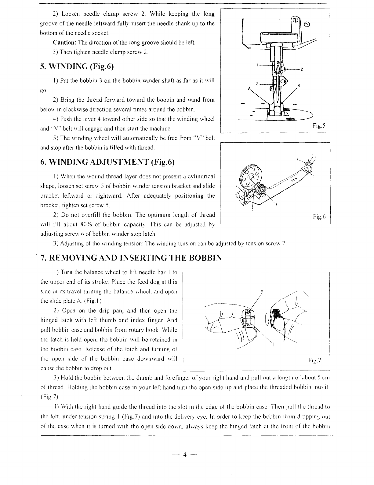
2)
Loosen needle clamp screw
of
groove
bottom
5.
go.
below
and
and stop after the bobbin
6.
shape, loosen set
bracket left ward or rightward. After adequately positioning the
bracket, tighten set screw
mil
adjusting sere\\
the needle leftward fully insert the needle shank up to the
of
the needle socket.
Caution: The direction
J)
Then tighten needle clamp screw
WINDING
l)
Put the bobbin J on the bobbin winder shaft
2) Bring the thread forward toward the boobin and wind from
in
clockwise direction several times around the bobbin.
4) Push the lever 4 toward other side so that the winding wheel
··v··
belt will engage and then start the machine
5) The v\inding \\heel
WINDING
I)
When the \vound thread layer does not present a cylindrical
2)
Do
not overfill the bobbin The optimum length
fill
about
J)
Adjustmg
(Fig.6)
ADJlJST~1ENT
screvv 5 of
80'%
()of bobbin winder stop latch
of
the winding tension: The winding tension can
of
the long groove should be left.
vvill
is
filled with thread.
bobbin winder tension bracket and slide
5.
of
bobbin capacity This can
2.
While keeping the long
2.
as
far
automatically be free from
(Fig.6)
be
adjusted by
as
"V"
of
it will
belt
thread
be
adjusted
by
tension screw 7
FigS
Fig.o
7.
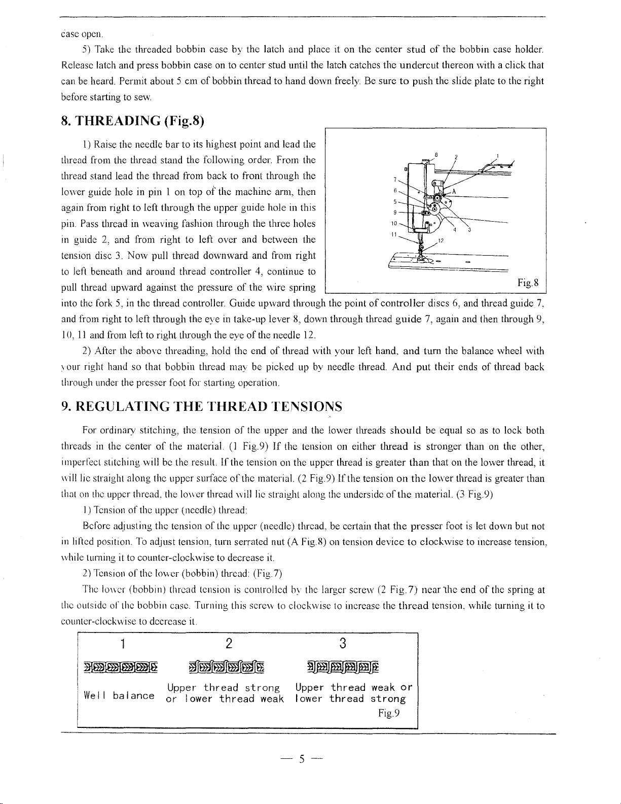
RE!\10VING
I)
Turn the balance wheel to lift needle bar I
the upper end
in
side
the slide plate
hinged latch with left thumb and index finger And
pull bobbin case and bobbin from rotary
the latch
the boobin case. Release
the open side of the bobbin case downward will
cause the bobbin
of
(Fig
Its
2)
3) Hold the bobbin bet
thread Holding the bobbin case
7)
-n
the left. under tension spring l (Fig
or
the case \\hen
of
travel turnmg the balance wheeL and open
A (Fig
Open
on
is
held open. the bobbin will be retained
\Vith
the
AND
its
stroke Place the feed dog
I)
the drip pan, and then open the
to
drop out.
right hand
it
is
tumcd with the open side
INSERTING
hook. While
of
the latch and tuming
vvcen
the thumb and forefinger of your right hand and pull out a length
in
your left hand turn the open side
gwde
the thread into the slot
7)
and into the dciiVef) eve.
at
THE
to
this
In
of
do\\11.
BOBBIN
L__
__________________
up
and place the threaded bobbin lllto
Ill
the edge
alwavs keep the hinged latch
or
the bobbin case. Then pull the thread
In
order
to
keep the bobbin
2
at
!'rom
the front
Fig7
_
or
about 5
dropping out
or
the
bobbin
em
It
to
--
4
--
Page 7
case open.
5) Take the tlu·eaded bobbin case
Release latch and press
can be heard.
before starting to sew.
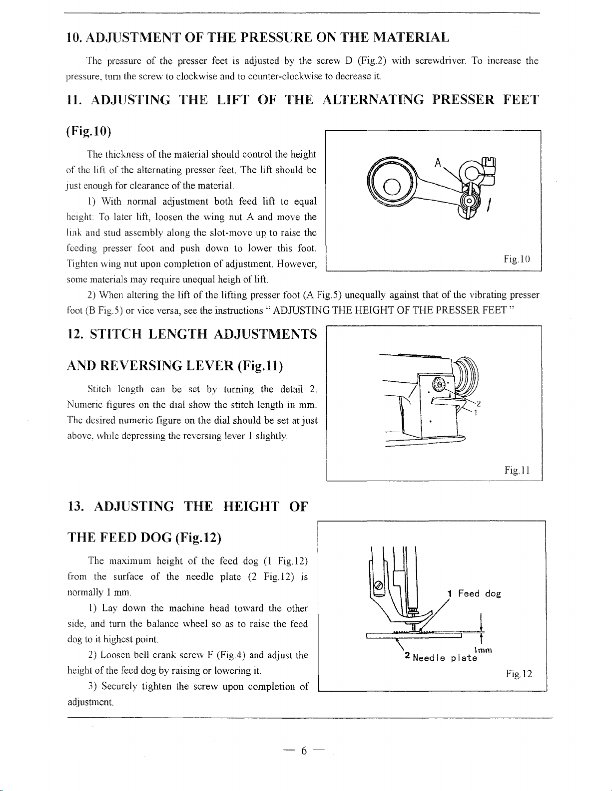
8.
THREADING
l)
thread from the thread stand the
thread stand lead the thread from
lower guide hole in pin 1 on top
again from right to left
pin.
Pass thread in weaving fashion through the three holes
in guide
tension disc
to left beneath and around thread controller
pull thread upward against the pressure
into the fork
and from right to left through the eye in take-up lever
I 0,
ll
2)
\our
right hand so that bobbin thread may be picked up by needle thread.
through under the presser foot for starting operation.
Permit about 5
Raise the needle bar
2, and from right
3.
Now
5, in the thread controller. Guide upward through the point
and from left to right through the eye
.ASter
the above threading, hold the end
bobbin
case on to center stud until the latch catches
em
of
(Fig.8)
to
its highest point and lead the
tlu·ough the upper guide hole in this
to
left over and
pull thread downward and from right
by
the latch and place it on the
bobbin
follovving order. From the
back
of
thread
to
to front through the
the machine
of
am1,
between
4, continue to
the wire spring Fig.8
of
the needle 12.
of
thread with your left hand.
hand down freely. Be sure
then
the
8,
down through thread
center
the
10
of
controller
And
stud
of
the bobbin case holder.
undercut
to
guide
and
thereon with a click that
push
the slide plate to the right
discs 6, and thread guide
7, again and then through 9,
tum
the balance wheel with
put
their ends
of
thread back
7,
9.
REGULATING
For ordinary stitching, the tension
threads
imperfect stitching will be the result.
will lie straight along the upper surface
thot
in
while tuming it to counter-clockwise to decrease it.
the outside
counter-clockwise to decrease it.
in
the center
on
the upper thread_ the lO\\er thread will lie straight along the underside
I) Tension
Before
lifted position. To adjust tension, turn serrated nut
2) Tension
The 10\\er (bobbin) threod tension
of
the upper (needle) thread:
ad_i
usting the tension
of
the lower (bobbin) threod (Fig 7)
or
the bobbin case. Turning this screw to clockwise to increase the
THE
of
the material. (J Fig. 9)
THREAD
of
If
the tension on the upper thread is
of
of
the upper (needle) thread, be certain that
is
the upper and the lower threads
the material. (2 Fig.9)
controlled
2
~
1 Upper
j
We
II
ba I
ance
or
thread
I ower
strong
thread
weak
TENSIONS
If
the tension on either
If
(A
Fig.
S)
on tension
hy
the larger screw
3
Upper
lower
thread
thread
thread
greater
the tension
of
device
(2
weak
strong
Fig.9
should
is
than
on
the
the
the
presser
to
Fig.
7)
thread
or
be equal so as to lock both
stronger than on the other,
that on the lower thread, it
lower
thread
is
greater than
material.
clockwise
neor"thc
(3
Fig.9)
foot
is
let down but not
to increase tension,
end
of
the spring at
tension. while turning it to
-5-
Page 8
10.
ADJUSTl\1ENT
OF
THE
PRESSURE ON
THE
MATERIAL
The pressure
pressure, tum the
11.
ADJUSTING
of
the presser feet is adjusted by the screw D (Fig.2) with screwdriver. To increase the
scre"v to clockwise and to cmmter-clockwise to decrease it.
THE
LIFT
OF THE ALTERNATING PRESSER
(Fig. I 0)
The thickness
of
the lift
just
height
llllk and stud assembly along the slot-move up
feeding presser foot and
Tighten
some
foot (B Fig.5) or vice versa, see the
12.
of
enough for clearance
1) With normal adjustment
To later lift,
\Ving
materials may require unequal heigh
2) When altering the lift
STITCH
of
the material should control the height
the alternating presser feet.
of
the material.
both
loosen
nut upon completion
LENGTH
the
push
of
wing
nut
down
of
adjustment. However, Fig.l 0
the
lifting presser foot
instructions"
ADJUSTMENTS
The
feed lift to equal
A and
to
lower
of
lift.
lift should
move
to
raise the
this foot.
ADJUSTING
be
the
(A
Fig.5) tmequally against
THE
HEIGHT
OF
that
THE
of
the vibrating
PRESSER
FEET
presser
FEET"
AND
Numeric figures
The desired numeric figure
above, while depressing the reversing lever 1 slightly.
13.
REVERSING
Stitch length
on
can
the
ADJUSTING
LEVER
be
set
by
dial show the stitch length
on
the
THE
(Fig.ll)
turning the detail
dial should
be
HEIGHT
set
THE FEED DOG (Fig.l2)
The
maximum
from the surface
normally l mm.
l)
Lay
down
side, and turn the balance wheel so as
dog to it highest point.
2) Loosen bell
height
of
the feed dog
3) Securely tighten the
adjustment.
height
of
the
crank
of
the
feed
dog
the
needle
machine
screw F (Fig.4) and adjust the
by
raising
head
or
screw
plate
toward
to
lowering it.
upon
(1
Fig.l2)
(2
Fig.l2)
the
raise
the
completion
in
mm.
at
just
OF
is
other
feed
of
2.
2 Need I e
1 Feed dog
lmm
pI
ate
Fig.ll
Fig.l2
-6-
Page 9
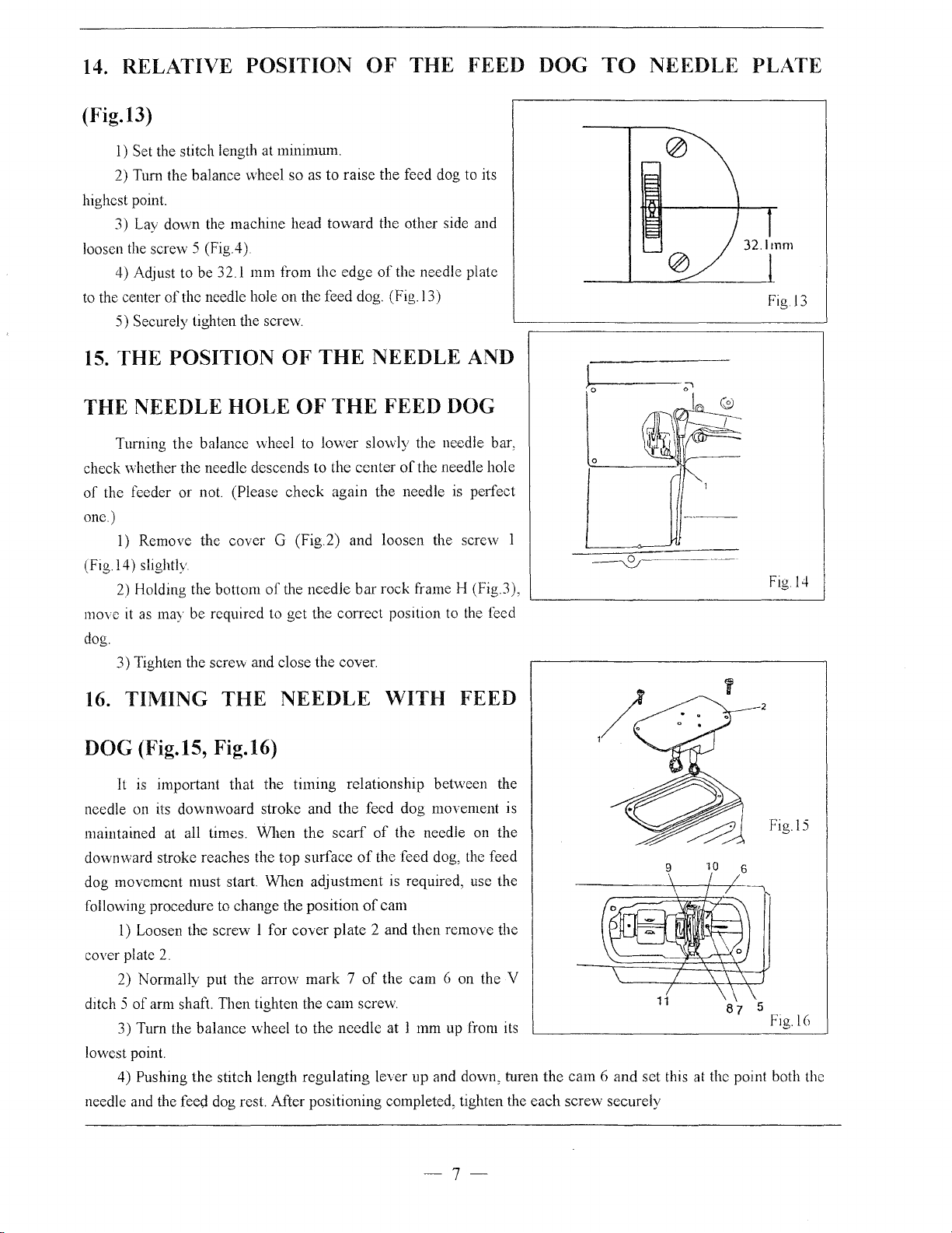
14. RELATIVE POSITION
OF
THE FEED DOG
(Fig.13)
1)
Set the stitch length
2) Tum the balance wheel so as to
highest point.
3) Lay down the machine head toward the other side and
screvv
loosen the
4) Adjust to be 32.1 mm from the edge
to
the center
5) Securely tighten the screw.
15.
THE POSITION OF
5 (Fig.4)
of
the needle hole on the feed dog. (Fig.l3)
at
minimum.
raise the feed dog to its
of
the needle plate
THE
NEEDLE AND
TO
NEEDLE PLATE
Figl3
THE NEEDLE
Turning the balance wheel to lower slowly the needle bar,
check whether the needle descends to the center
of
the feeder or
one)
1)
Remove the cover G (Fig.2) and loosen the screw 1
(Fig 14) slightly.
2)
Holding the bottom
move
it
as
may be required to get the correct position to the feed
dog.
3) Tighten the
16. TIMING THE
HOLE OF THE FEED DOG
of
the needle hole
not
(Please check again the needle
of
the needle
screw and close the cover.
NEEDLE
bar
rock frame H (Fig 3),
WITH FEED
is
perfect
DOG (Fig.15, Fig.16)
It
is
important that the timing relationship between the
needle on its downwoard stroke and the feed dog movement is
maintained at all times. When the
downward stroke reaches the top surface
dog movement must start. When adjustment is required, usc the
following procedure to change the position
l)
Loosen the screw l for cover plate 2 and then remove the
cover plate
ditch 5
lowest point.
needle and the feed dog rest. After positioning completed, tighten the each screw securely
2.
2) Normally put the arrow mark 7
of
arm shaft. Then tighten the cam
3) Tum the balance wheel to the needle at l mm up from its
Pushing the stitch length regulating lever up and down, turen the cam 6 and set this at the point both the
4)
scarf
of
the needle on the
of
the feed dog, the feed
of
cam
of
the cam 6 on the V
screw
87
Figl4
Fig.l5
5
Fig.l(J
-7-
Page 10
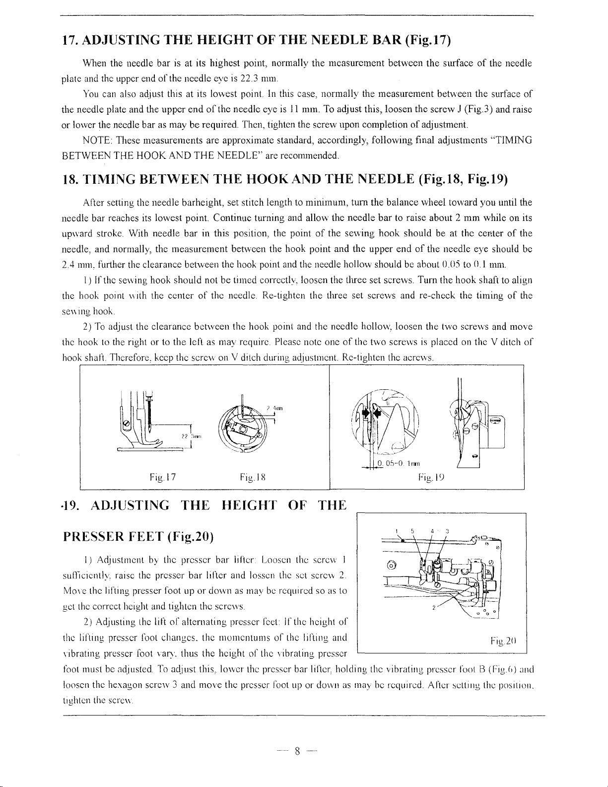
17. ADJUSTING
THE
HEIGHT
OF
THE
NEEDLE
BAR
(Fig.17)
When the needle bar is at its highest point, normally
of
plate and the upper end
You
can also adjust this at its lmvest point. In this case, normally the
the needle plate and the
or
low·er the needle
NOTE: These
BETWEEN
18.
TIMING
After setting the needle barheight, set stitch length to
needle bar reaches its lowest point.
upward stroke. With needle
needle, and normally, the
2.4
111111,
the hook point
se\\ ing hook
2)
the hook to the right
hook
THE
HOOK
BETWEEN
further the clearance between the hook point and the needle hollow should
1)
If the sewing hook
"ith
To
adjust the clearance
shari
Therefore, keep the screw on V ditch during adjustment. Re-tighten the acrc\vs.
the needle eye
upper
end
bar
as may
measurements
the
or
be
AND
THE
bar
measurement
should
center
to
the
left as may require Please note one
of
between
is
22.3
of
the needle eye is
required. Then, tighten the screw upon completion
are approximate standard, accordingly, following final adjustments
NEEDLE''
THE
Continue
in this position, the point
not
the needle. Re-tighten the three set screws and re-check the timing
HOOK AND THE
turning and allow the
benveen the hook point and the
be
timed correctly, loosen the three set screws. Turn the
the hook point and the needle hollow, loosen the
the
mm.
11
mm. To adjust this, loosen the
are recmmnended.
minimum,
of
measurement
NEEDLE
tum
the balance wheel to\vard you until the
the
needle
se\\ing
of
the
bar
upper
t\vO
between
measurement
the
of
adjustment.
(Fig.18, Fig.l9)
to raise about 2
hook
should
end
of
the needle eye should
be
about
screws
is
surface
between the surface
screw
be
0.05
two
placed on the V ditch
of
the needle
J (Fig.3) and raise
"TIMING
mm
while
on
at the center
to
0.1
hook
screws and move
of
mm.
shaft to align
of
of
its
the
be
the
of
Fig l
C)
·19.
ADJUSTING
Figl7
THE
Fig.! X
HEIGHT OF THE
PRESSER FEET (Fig.20)
l)
Adj
ustmcnt by the presser
suffiCiently, raise the presser
Mm
e the lifting presser foot up or down as may be required so as to
get the correct height and tighten the screws.
2) Adjusting the lift
the lifhng presser foot changes. the momentums
nbrating
foot must be adjusted To a4just this, 10\ver the presser bar lilicr, holding the vibrating presser foot B (Fig.()) and
loosen the hexagon screw 3 and move the presser foot up or
tighten the sere\\
presser foot vary. thus the height
of
altcmating
bar
lifter Loosen the screw l
bar
lifter and lassen the set screw 2
presser f'cct
of
lf
the height
of
the l1fting and
the vibrating presser
--
8
--
dovvn
of
Fig 20
as
nwy he required. After setting the position.
Page 11
20. TIJ\1ING OF THE VIBRATING PRESSER FOOT
This is the normal
, ibrating presser foot
the
vibrating presser foot
that the vibrating presser
irregular stitches.
(Fig 20) and adjust the rotating
screws
21. ADJUSTJ\1ENT
CONNECTION
lnconect
stitch length
To tnerease the clearance, loosen the
should be done with
adjustment, tighten the
clearance
or
overheating, etc. To
22.ADJUSTING
Normally. the thread
thread until the needle reaches to the goods, and
the needle and passing
l)
For more
the stop to the right
2)
To
adjust the
Turn the tension stud G slightly to the left to strengthen the tension (to lighten
tension. turn to the right)
completion
of
adjustment
23.ADJUSTMENT
timing
should
should
foot
To
adjust
AND
between
tuming
screw
THE
of
the
controller
(For
less action,
tension
when
tum
the
balance
reach
the reed
leave the feed dog after the
must
this, set the lift
position
OF
FEED
the fork 8
adjust
the
balance
which
is loosened to touch the feed fork.
dog
tightly
of
hold
of
the
THE CLEARANCE
FORK
of
this,
screw
and turn the scrcvv to left or
wheel
THREAD
controller
upper
action
spring:
\\ith a scre\\dri\er.
OF
spring I should hold slack
thread through the bobbin case.
on
the
thread:
move
to the left). Tighten the screw.
Loosen
the serrated nut 4 and the
NEEDLE BAR STOP POSITION
wheel
toward
earlier than the
the
goods
the alternating
cam
5 (Fig.20) faster
COLLAR
feed forked
open
the
toward
needle
while
connection
cover
plate.
you
needle
eye
the
presser
(Fig.15,
to
CONTROLLER
it
should pause
Loosen
Tighten the sere\\ and nut
the
stop
while
screw
you, after
eye
comes
has left
needle
feet to
or
slower as
BETWEEN
and feed
Remove
get
correct
SPRING
of
the
upper
raising
2.
move
screw
lowering
the
is
passing
equal,
may
to,
feeder
the
presser
and
when
This is due the
the
loosen
be
desired, and tighten the
FEED FORKED
Fig.l6)
fork
collar
9 will bring irregular
the
coyer
plate
and
counter-clockwise.
clearance.
Upon
(Fig.21)
of
5.
the
upon
bar
lifter, the
the needle raises,
reason
goods
for aYoiding
the
two
screws 4
the oil reservoir.
This adjustment
completion
3 2
Fio.2]
of
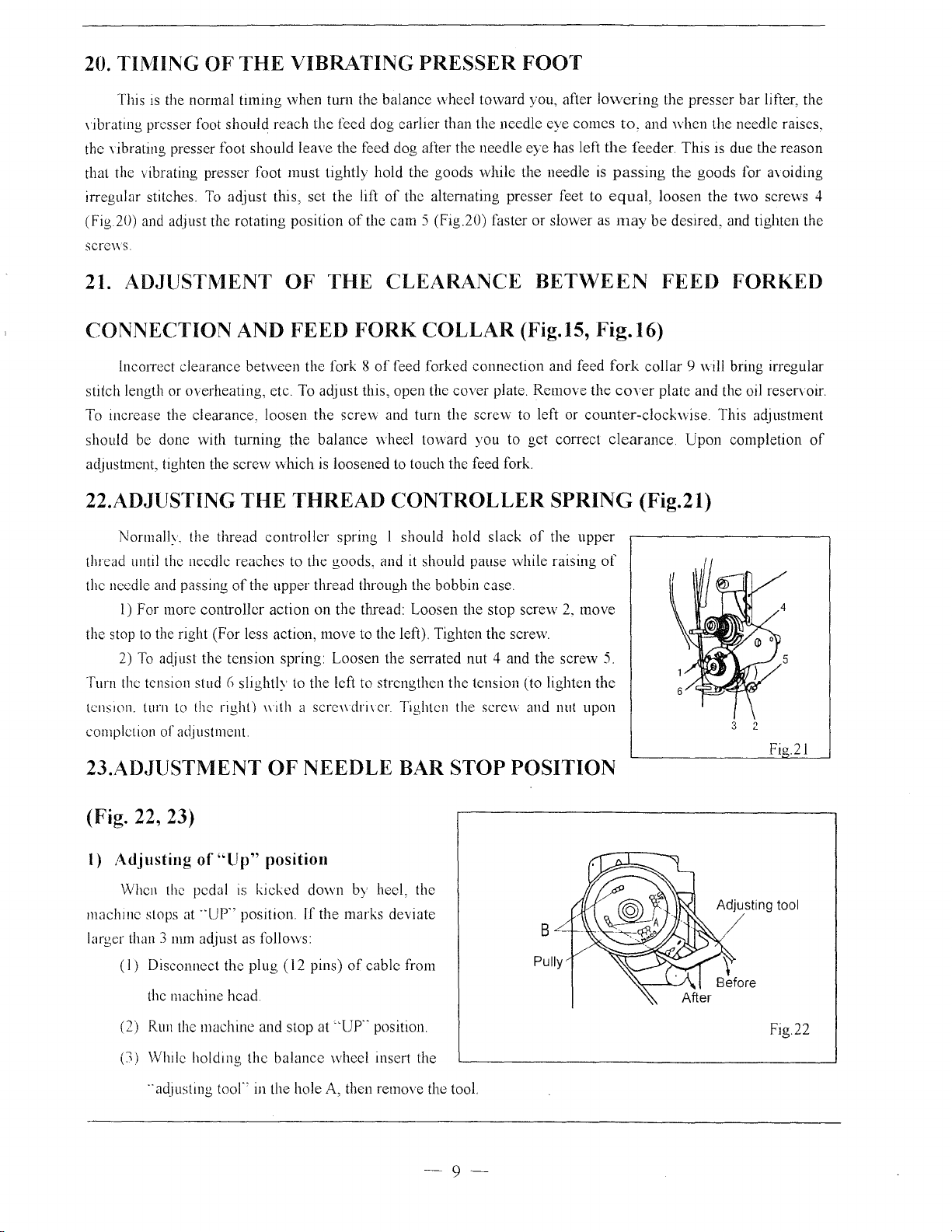
(Fig. 22, 23)
l)
Adjusting
When the pedal is
machme
larger than 3 nun adjust as follows:
stops at --up·' position.
(I)
Disconnect the
the machine
(2) Run the machine and stop at
(:I) While
..
of"
holding
adJusting
Up" position
kicked
plug ( 12
head
the
toor'
in the hole A, then remove the tool.
down
lf
the marks deviate
pins)
''UP
balance
wheel
by heel, the
of
cable
..
position
insert the
from
Pully
-9-
Adjusting
tool
Fig.22
Page 12
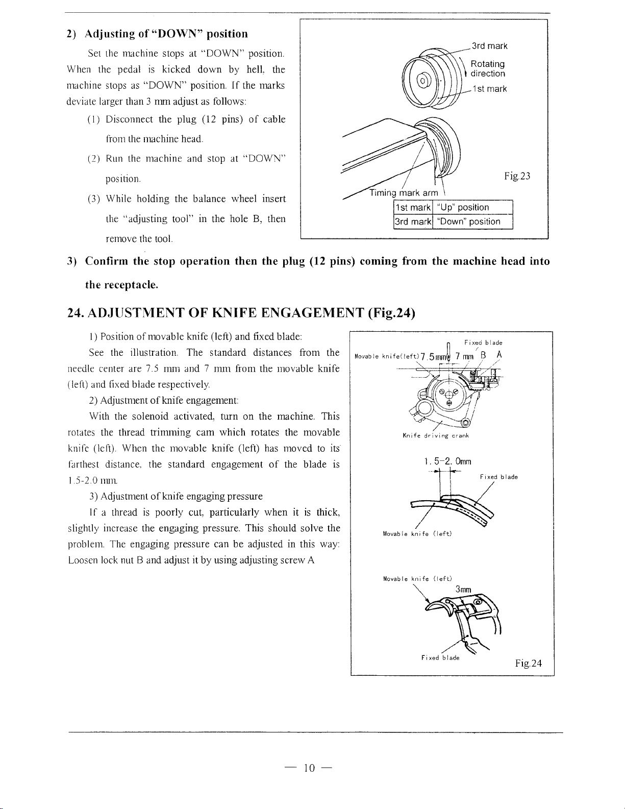
2) Adjusting
of
Set the machine stops at
When the pedal
machine stops as
is
"DOWN"
deviate larger than 3
(I)
Disconnect the
"DOWN~~
position
"DOWN"
kicked
down
position.
mm
adjust as follows:
plug
(12 pins)
position.
by
helL the
If
the marks
of
cable
3rd mark
\ Rotating
\ direction
\
1st mark
from the machine
(2)
Run the
machine
position.
(3) While holding the
"adjusting tool" in the hole B, then
the
head
and stop at
balance
"DOWN"
Fig.23
wheel insert
remove the tool.
3)
Confirm the stop operation then the plug (12 pins) coming from the machine head into
the receptacle.
24. ADJUSTMENT OF KNIFE ENGAGEMENT (Fig.24)
I)
Position
See the illustration
needle center are 7 5
(left) and fixed blade respectively
2) Adjustment
With the
rotates the thread
knife (left). When the movable knife (left) has
farthest distance. the
5-2.0
I
nnn
3) Adjustment
If
a thread
slightly increase the
problem
Loosen lock nut
of
movable knife (left) and fixed blade:
The
standard
nm1
and 7
nun
of
knife engagement:
solenoid
is
activated, turn
trinuning
of
knife engaging pressure
poorly
engaging
cam
standard
engagement
cut, particularly
pressure. This should solve the
which
The engaging pressure can
B and adjust it
by
using adjusting screw A
distances from the
from the movable knife
on
the machine. This
rotates the movable
moved
of
the
when
be
adjusted in this way:
to
blade
it is thick,
its
is
Movable
knife(leftl7
Movable
n
Fixed
.5rnm~
7
r-
(left)
---l--:--· /
mm
"...,_
knife
b I a
1
B A
//
de
-10-
Movable
knife
""'
Fixed
(left)
3mm
b I
ade
Fig.24
Page 13

A.ARM BED AND ITS ACCESSORIES
53
4""-.
~
~'
3
52
0
0
171
0
18~
16
-11-
Page 14

A.ARM BED AND
Fig.
No.
A01
A02 HA06030080 Screw
A03 H2020M0069 Felt
A04 H2020M0067
AOS
A06
A07 H2020M0068 Oil wick
A08 H2400J2010 Oil cap
A09 H2400J2020
A10
All
A12 HA124B0711 Slide plate
Al3
Al4
Al5
A16
Al6
Al7
A18
A19
A20 H3108B0691
A21
A22
A23
A24
A25
A26
A27
A2g
A29
A30 H3100G2230
A30 H4200G2010
A30
A31
A32
A33
A34
A35
A36
A37
A38
A39
A40 H3111B0703
Part
No.
H3115B0721
Ann
Felt
H2020M0066
Ann
H2020M0068 Oil
Oiling
H3106B0671.
HA300B2170
Face plate 1 1
Screw
HA124B0713 Screw
HA124B0712 Slide plate spring
H2000B2050 Screw 2 2
H3100B2090 Needle plate 1 1 1
H4500B2020 Needle plate 1
H005008060 Spring washer 1 1
H2009B0653
Leg
H3108B0692 Felt 1 1
Thread guide
HA500C2070
Screw
HA300B2130 Screw 2 2
H2000B2040 Cloth guide plate 1 1 I
HAI06B0676 Screw
HAI06B0675 Thread guide 1 1 I
H2400B2080
H2400B2070 Thread guide 1 I
.
H2000M0090
Screw
Oil
H2000M0080 Felt
Thread tension releasing pin
Thread tension releasing pin(long)
H420002020
H2504C6510
H3111B0704
H31611B311
HA300B2080
H3111B0702
H3221B6819
Thread tension releasing pin( short)
Screw
Tension releasing lever
Screw
Screw
Thread controller spring
Thread controller spring stop
H324giBC21 Screw
H2504C0654
Thread guide
H2504C0658 Nut
Ser
ITS
ACCESSORIES
.......
I
00
.......
Description
cover( right)
'D
0
u
0
1 1 1
2 2 2 2
1 1 1
2 2 2
oil box( right)
wick
1 1
1 1 1
1 1
1 1
felt 1 1
2 2 2 2
1 1 1
2 2 2 2 SM3/32(56)x2.2
1 1 1
1 1
1 1
1 1 1
1 I I 1
I
cap I I 1
2 2 2
I I
2 2 2
I
I
1
I
1 I I
I I I
I
I
screw
1
N
u
(/).
Q
I I
....... .......
I
00
.......
'D
0 0
u u
0
I
00
.......
'D
0
1
1
1
1
1
2
1
1
1
I
2
I I
1
1
I
I I
I I
I
1
I
I
I I
I I
1 1
,......
I
00
.......
.,..,
0
u
0
Remarks
1
1
2
1
1
1
1
1
1
SM11/64(40)x9
1
1
2 SM11/64(40)x6.5
1
1
I
1
1 SM9/64( 40)x5
SM11/64(40)x5.5
2
I
SM9/64(40)x6
I
I SM3/16(28)x
13
1
1
2
I
2
I
I
SMI5/64(28)x6.8
I
I
1
I
I
1
SM3/32(56)x6
1
-
12-
Page 15

A.ARM BED AND ITS ACCESSORIES
u
(fJ
I I
I
-
Fig.
No.
A41 HA115B7010 Stop disc 1 1 1
A42
A43
A44
A45
A46
A47 H31611B211
A48 HA7311C606 Screw 1 1 1
A49
ASO
A51
A52
A53
A53
A
A54
A
A56
A57 H3100B2060
A58
A
A59
A60 H2000M0180
A61
A62
A63
A64
A65
A66
Part
No.
HA607B0068 Tension releasing spring 1
H2504C0657 Thread tension releasing plate
H2504C0656 Thread tension disc 2 2 2
H2504C0121
HA310B0701 Nut
H3100B2070 Thread guide 1 1 1
H31611Blll
H2504C0013 Thread tension stud 1 1 1
HA300B2170 Screw
H4205l0661
H3107B0681
54
H2000B2010 Rubber plug 1
HA307E0674 Rubber plug 1 1
55
HA300B2170 Screw 5 5 5
HA300B2160 Screw
H2400B2100 Thread guide 1 1
H4206B0066 Thread tension complete 1
58
HA700B2060 Screw 2 2
H2000M0190 Sealing washer 1 1 1
H2000M0200 Gland 1 1 1
HA300B2170 Screw 5 5
H2400B2050 Oil guard 1 1 1
H2400B2060
H3111B0705 Plate spring 1 1 I
Thread tension releasing pin
Pin
Tension bracket 1
Arm
side plate 1
Arm side plate 1
Thread take-up lever cover
Oil
window
Plate for oil guard
Description
00
\0
-
0
u
0
I I
-
00
\0
-
0 0
u
0 0
1
1 1 1
1 1
1 1
1 1 1
1 1
2 2
1
1 1 1
1 1 1
1 1
1 1
I
N
0
-
00
\0
-
u
1
1
1
2
1
5
I
-
00
lr)
-
0
u
0
1
1
1
2
1
1
1
1
1
1
1
SM11/64(40)x9
2
1
1
5
SM11164(40)x10
1
1
1
2
1
1
1
SM11!64(40)x9
5
1
1
1
Remarks
-13-
Page 16

B.ARM SHAFT MECHANISM
22
23
24
16
21
------
,-
1 18
20
I
I
I
:
19
I/
r#f
I
\_-----
32
~"
~----~--·
34
\
-
_3_3_~--
--~---
---
41
.--
4
~
---
14
~-
15
I
I
I
I
I
\
I
I
..-'
-
14-
Page 17

B.ARM SHAFT MECHANISM
Fig.
No.
BOl
802
803
804
805
806
B07
808
809
BlO
Ell
812
813
814
Bl5
816
817
818
819
B20
821
822
823
824
825
825
826
826
827·
828
829
830
830
831
832
832
833
834
835
836
837
838
839
Part No.
H3100C2110
H2009B0743 Felt
H31133Bl04
HA100C2020
H31122B204
HA105D0662
HA.105D0661
HA113D2112
HA108D0663 Set screw
HA112D3012 C-type ring
H3100E2010
HA3411D208 Slide block
HA.3411D308
H2000C2040
HAll
OD0672
H3100C2070 Hinge pin
H2009B0732
HA300B2110 Rubber plug
H3100C2050 Oil wick
H3100C2030 Oil
HAIOOC2020
H3100C2020 Hinge pin
H3100C2010
H3100C2040
H4200C2060
H3100C2060
HA100C2070
H4206C800l
H3100C2130
H3100C2080
HA105D0662
HA.l08C0663
HA307C0662
H3100C2120
H4204C0651
H3100C2090
H409050140
H2017M0067
H2017M0065
H31122BI04
H2009B0731
HAIOOC2020
H20ll!C206
Ann
shaft
Ann
shaft bushing(left) 1 1 1
Screw
Ann
shaft bushing(middle) 1
Screw
Ann
shaft
bevel gear for
Feed and feed lifting eccentric
Screw
Balance wheel
Screv:
Ann
shaft bushing(right)
wick
Screw
Thread take-up lever
lever
Slide
Needle bar cormecting stud
Needle
bar
screw
Set
Screw
Ann
shaft oil packing stop screw
wick
Oil
Screw
Set screw
screw
Set
wick
Oil
Needle
bar
Needle bar
Screw
Bevel gear cover( up-backward)
Bevel gear cover(up-foreward)
Felt
Felt
Screw
Felt
Description
collar
arm
shaft
cormecting stud
crank
crank
N
u
r/1
Ci
I I
I
-
00
- -
00
\C;
-
0
\C; \C;
- -
u
0 0
0
u u
0
1 1 1
1
1 1 1
2 2 2
1 1 1
1 1 1
8
1 1
1 1 1
1 1
2 2 2
1 1
, ,
"'
1 1 1
1 1 1
1
1 1 1
1 1 1
I
00
0
1
1
8 8
"-
1 1
I
1
1
1
1
1 1 1 I
I I
1 I 1
I
1 1 1
1 I
I I 1
1
1 I 1
I
1 1 I 1
I
2 2 2 2
I I
1 1
1 1
1 1
I 1 1 I
I 1
I
I I
I
1
1 I
1
2
I
I 1
1
1
1
1 I
1 I
I
-
00
lr)
-
0
u
0
1
1
1
SM15/64(28)xlO
1
1
SMl/4
2
1
1
SM114(40)x7
8
1
1
1
2
1
Siv1 i 5/
2
1
1
1
1
1
SMI5/64(28)x!O
I
1
I
SM9/32
I
SM9/32
I
1
SMl/4
SMl/4
1
SMl/4
I
1
1
SM 15/64(28)x
Remarks
(40)
64(28)x
(28)
(28)
(40)
(40)
(40)
x4
i 2
X4
x7
x6
10
-15-
Page 18

B.ARM SHAFT MECHANISM
I
-
Fig.
No.
B40 H20111C106 Oiling felt presser pin 1 1
B41
B41
Part No. Description
HA100C2060
H4204C0652 Screw
Screw
00
\D
-
0
u
0
1 1 1 SM9/32
N
u
C/J
0
I I
I I
-
-
00
00
\D
\D
-
-
0 0
u u
0
0
I
-
00
lr>
-
0
u
0
1
1
1
SM9/32
Remarks
(28)
X12
(28)
X\2
-16-
:
I
Page 19

C.ROTATING
HOOK
SHAFT MECHANISM
4
\$\
~
8
~
22
25
n.·
--u
~
~--21
m--20
18
___
15
13
~~ y ~
~~14
'---.._1
0
\
12
27 28
26
-17-
Page 20

C.ROTA TING HOOK SHAFT MECHANISM
I
-
Fig.
No.
CO!
CO!
CO!
C02
C02 Hl!OOE2010 Bobbin
C03 H2200C20SO Rotating hook complete
C03 H3!00D2160 Rotating hook complete
C03 H2300E2010
C04 H2000M0070
cos
cos
C06
C07 H2009B0772
C08 H2000M0060
C09
C09 H3!00D20SO
C09
CIO
CIO
Cll
Cll
Cl2
Cl3
Cl4
CIS
Cl6
Cl7
.CI8
Cl9
C20
C21
C22
C23
C24
C25
C26
C27
C28
C29
C30
C31
C32
C33
Part No.
HA900E2030
H3!00D2170 Bobbin case complete
HA600E2080 Bobbin case complete
HA600E2060 Bobbin I
H4200D20!0 Rotating hook positioner
HA600E2040 Rotating hook positioner
HAIOOE21SO Screw
H2200C2030
H2000E2030
H2009B0751
H31!8SB104
H2009B0711 Felt
H3118SB204
H2000I2080
HA113D2212
HA108C0663
HA113D2222
H2009B0711 Felt
HAIOOC2020
H2009B0721
H3104D06SI
H2009B071
HAIOOC2020
H31
196B104
HAI08C0663
HAl
13D2122
H2009B0712
H2018M0066
HA300B2110
H4090SOI40
H2018M006S
H2008M006S
H2008M0066
H2008M0067
HA300B2170
Bobbin case complete
Rotating hook complete
for oil adjusting screw I
Spring
Hook shaft bushing(left)
adjusting screw
Oil
Rotating hook shaft
Rotating hook shaft(left)
Rotating hook shaft
Hook shaft bushing(right)
Hook shaft bushing(right)
Felt
Screw
Bevel gear for hook shaft
screw
Set
Bevel gear for vertical shaft(lower)
Screw
Vertical shaft bushing(lower)
Vertical shaft
Felt
I
Screw
Vertical shaft bushing(up)
screw
Set
Bevel gear for vertical
wick
Oil
Bevel gear cover(lower-backward)
Rubber plug
Screw
Bevel gear cover(lower-foreward)
pipe
Oil
Felt
Oiling felt spring
Screw
Description
shaft(up)
00
\J:)
-
0 0
u
0
I
I
I I
I
I I
I I
I I
I I
1
I
4
I
I
I
I
I
I
I
I
2
I
2
I
2
I
I
I
I
I
I
N
u
r./J
a
I
I
I
I
-
-
00
00
\J:)
\J:)
-
-
0
0
u u
0 0
I
I
I
1
I
I
I I
I
I
I
1
I
I
I
I
I
I
I
I I I
4
4
I 1 I
I I I
I I
I
I
I
I
I
I
I I
I
I
2 2
I I
2 2
I I
2 2
I I
I
I
I I
I I
I I
I I
I
-
00
1£)
-
u
0
I
I
I
SM!l/64(40)x!O
I
I
I
SMII/64(40)x~U
I
SMl/4
4
SM I S/64(2X)x I 0
I
I
I
I
SM 15/M(2X)x I 0
I
I
SMI/4
2
I
2
I
2
M5xl4
I
I
I
I
I
SMII/64(40)x'J
I
Remarks
(40)
(40)
x7
x7
-
18-
Page 21

C.ROT A TING
Fig.
No.
C34
C35
C36
C37
C37
C38
C38
C39
C39
C40 H2000I2080
C41
C42
C43
C44
C45
C46
C47 H3100D2100 Pin I
C48 B3100D2150 Fork 1
C4'.!
cso
('51
Part
No.
H3100D2060 Push button
H3100D2090 Push
H007013035 Stop ring
H312ID8001 Ratchet wheel I
H3!00D2080
HA307C0662 Screw 2
HAIOOC2090
HA704B0653
H3104B0074
H3106D0066 Safety clutch complete
H3100D2020
H3100D2130
H3100D2140 Screw
H3100D2120 Positioner
HAIOOC2090
H415050120 Screw I
HA.810E0691 Thread trimming eccentric
HAX10E06'.!2 Screw
HOOK
button
Hook
shaft lock ratchet
Screw
Hook
shaft bushing( middle) I
Hook
shaft bushing(rniddle) complete
screw
Set
Hook
shaft(right)
Positioner
Screw
SHAFT MECHANISM
Description
spring
-
00
\D
-
0
u
C)
I
N
u
(/J
0
I I
I I
-
-
00 00
-
\D
\D
-
0 0
u u
C)
C)
I
1
1
1
2
I
1
I
1
I
1
I
2 SM15/64
I
2
I
-
00
<n
-
0
u
C)
SMl/4
SMIS/64
SM11164(40)x8.5
M5xl2
Remarks
(40)
x6
(28)
(28)
x4.5
x4.S
-19-
Page 22

D.STITCH
REGULATOR
MECHANISM
-20-
Page 23

D.STITCH
Fig.
No.
DOl
D02
D03
D04 HA104F06S4
DOS
DOS
DOS
Part No. Description
HAI04F06SI Hinge pin
HA104F06S2
H3100E2170
H421!1E104 Feed regulator cam
H3IOOE2060
H4500E2010
REGULATOR
MECHANISM
Feed connecting link
Feed connecting link hinge pin 1
Screw
Feed regulator
Feed regulator
cam
cam
D06 HAI04F06S4 Screw 2
H2200D2030 Spring
D07
H2000F2030 Spring
D07
H2204D0651
D08
D09 H3!00E2230
H2006C0661
D09
HA700B2120
DIO
HA109F0671 Feed regulator screw
Dll
HA109F0674
Dl2
Dl3
Hll04F0651
H3!00E2070 Dial
Dl3
HA!09F0673 Screw
Dl4
HA!OOF2070
DIS
Dl6
Hi\IOOF2080
HA!OOF2090
Dl7
HA309F0671
Dl8
H2005F0065
Dl9
HA300C2030
D20
HA113F0683
D21
HA104F0654
D22
[)23
HAIOOF2110
H4205E0066
D24
H3111E0065
m4
H2204D0654 Spring
D25
ILA.806C067 5
D26
1)27
H007013040
D28 H2204D0652
[)29
H2204D0653
])30
HAIOOC2190
])31
H2405D0664
retainer
retainer I
Reverse link
Hinge pin for feed regulator 1
Hinge pin for feed regulator 1
Rubber plug 1 1 1 1
bar
0-ring
Dial 1
Rubber plug I I I 1
Stopper
Spring
pin
for stopper pin I I I
Reverse feed lever I I I 1
Reverse feed lever pin I I 1 1
Screw
Screw I I I I
Screw
Washer
Reverse feed lever crank complete I
Reverse teed lever crank complete
Spring retainer
Stop
ring
Pin
retainer
Spring
Screw
Screw
......
I
00
......
'-D
0
u
c.:J
I I
1
Ci
I I
......
......
I I
00
00
......
......
'-D
'-D
0 0
u u
c.:J
c.:J
1
1 1 1
N
u
(/1
I 1 1
1 1
1
1
1 1
2 2 2
1
1
1
1 1
1 1
1
1
I I
I
2 2
2
1
1 1
I I
I
I I
2
2
2
I I 1
I I I
I
I
I
I
I
2
I I
1
......
I
00
......
tn
0
u
c.:J
1
1 SM1S/64
1
SM1S/64
1
1
1
I SM3/16
1
I
2
SMII/64(40)x8
2
SMIS/64
I
SMII/64(
1
Remarks
(28)
x10
(28)
x10
(28)
x8
(28)
xJO
40)x8
-21-
Page 24

E.LOWER FEEDING MECHANISM
38
7
'
13-
16
·~~
17~~~----'
29
~
14
'
27
15
~
~
36
'
-22-
Page 25

E.LOWER FEEDING MECHANISM
Fig.
No.
EO!
E02
E03
E04 H3100E2110
E05 H3100E2120
E06 HA100C2020
E07 H2005L0065
E08
E10
Ell
El2
El2
El2
El3
El4
E15
El6
El7
El~
El9
E20
E2l H3!00E2040
E22
H23
E24
li25
E2(l
E27
E2X
E29
L30
li31
I
~32
L33
1·:34
I
~35
1;.3()
1~37
H3K
Part No.
H2009B0069
HA100C2020
HA304G0656 Screw
HA104G0012
H3116E0661
HA104G0654
H3100E2160
H4206E0671
H4500E2020
H3100E2140
H415050!20
H3100E2200
H3100E2190
HA305Gl012
H3100E2050
H3!00E2180 Nut I
H3!00E2!90
H3!00E2090
HAIOOG2070
I-IAI04F0654
H3100E2100
H2009B0069
IIAIOOC2020
1!2004K0065
l-1007009150 Stop
I !2UIIICI0(l
1!20IIIC206
I
131
OOE2030
IIA I
OOG2070
IIA30(lU0671
I
lA I OXU0(l6l
I
lA
I 05D0662
[ 1007013050
11AIOOG2130
Feed rock shaft bushing 2 2 2 2
Set
screw 2 2
Feed rock shaft crank
Feed bar shaft
Screw
Feed rock shaft
Screw
Feed bar
Screw
Feed dog 1
Feed dog
Feed dog
Feed lifting rock shaft crank(left) 1
Screw
Washer
Slide
block
Slide
block
Screw
Nut 2
Feed forked connection
Feed rock shall crank
Feed rock shall crank hinge pin
Screw
Screw
Feed litling rock shaft bushing 2
Screw
Feed lining rock shall
ring
Oiling
felt spring
Felt
Feed litling link
Feed rock shall crank hinge pin
Feed
titling rock shatl crank( right)
Feed rock shall collar
Set screw
Stop
ring
Washer
Description
shan
N
u
lZl
9
I
I
-
00
-
00
\0
-
0
\0 \0
-
u
0 0
t:l
u u
t:l
2 2 2 2
1 1 1 1
1 1 1 1
2
1 1 1 1
2 2 2 2
1 1 1 1
2 2 2 2
2,
2
1 1 1
1 1
I 1
1
1
2 2
1
1
1
3
1
2
1 I
2
1
I 1
1
I I
1 I
2
4 4
4
1
2
I
I
-
00
-
t:l
2
2 2 2
1
1
1 1 1
2 2
1 1
1 1
1 1 1
1 1 1
2 2
I 1 I
1 I
1
1
3 3
3
I 1
1
2 2
2
2
2
1 1
2 2
2
1 I
1
1 I
1
1
1
1
2
2
1
1
2 2
I
-
00
-
"'
0
u
t:l
SM 15/64(28)x
2
SM15/64(28)x
SM1/8(44)x6
1
M5x12
1
M4
M3
1
I
SM15/64
SM 15/64(28)x I 0
2
I
I
I
2
SM1/4(40)x4
4
1
2
Remarks
10
10
(28)
xJO
-23-
Page 26

F.NEEDLE BAR FEEDING MECHANISM
51-~
I
35
~~14
13
G)
22
®
46
®545
........
37
21
I
18
I
~
~
17
-24-
~
16
I
Page 27

F.NEEDLE BAR FEEDING MECHANISM
......
I
00
Fig.
No.
F01
F02
F03
F04
F05
F06
F07
F08
F09
F09
FlO
Fll
Fl2
Fl2
Fl3
Fl4
Fl5
Fl6
F17
F18
F19
F20
F21
F22
F23
F24
F24
F25
f-26
F27
F28
f-29
F30
F31
F32
F33
F34
F35
F36
F37
F38
F39
F40
Part No.
H3100F2010
H3100F2020
H3100F2030
HA700F2100 Screw
H3111F0651
H3100F2240
H3400C2020
H2000G2030
H3129F0693
HA500C2030
H3129F0691
HA100C2170
H3129F0692
H4500F2040 Needle bar complete 1
H3100F2270
H3406C0671
H602040240
HA100G2070 Hinge pin
H3132F0712
H3100F2310
H3100F2300
H3132F0711
H2010J0066 Nut
H3131F0703
H3126F0683
H4200F2010
H4500F2030
HAIOOC2020
H3100F2200
H3100F2220
HA7311CD06
H3100F2070
H3100F2060
H3100F2050
H3100F2040
H3100F2130
H005001060
H3100F2150
H3100F2170
H3100F2180
H3100F2160 Nut
H3115F0672
H31!5F0671 Screw
Crank link 1 1 1
Lifting bell crank
Link
Vibrating presser foot 1 1 1
Needle bar rack frame position bracket 1 1 1
Screw
Needle
Needle bar thread guide
Needle bar thread guide 1
Screw
Screw
Needle bar
Needle bar rock frame slide block
Needle bar rock frame slide block stud
Set
screw
Screw
Screw
Needle bar rock frame rock shaft crank connec
Needle bar rock frame rock shaft crank (right)
Needle bar rock frame rock shaft
Oil wick
Needle bar adaptor
Needle bar adaptor
Screw
Needle bar rock trame hinge stud
Needle bar rock frame
Screw
Vibrating presser bar
Vibrating presser
Vibrating presser
Screw
Screw
Washer
eccentric connecting collar
Litling
Litling eccentric connection
Needle bearing for
Lining eccentric connecting crank
Description
bar
extension spring
bar
extension
lithng
eccentric connectior
......
\0
0
u
CJ
1
1 1 1
1
1 1 1
1
1
1 1 1
1 1 1
1
1 1 1
1 1
1 1 1
1
1 1 1
1 1
1
I I 1
1 1 I
I I I I
1 1
I 1 1
1 1
I
I I 1
1 I 1
1
1 1
1 1
1 I 1
1 1 1
1 1 1
1 1 1
1 1
1 1
I
I 1
1
C'l
u
CZl
0
I I
......
00 00
......
\0
0
u
CJ CJ
I
I
-
\0
-
0
u
1
1
1
1
1 1 1
1
1
1
1
1
1
1
1
1
1
1
1
I
1
1 I
1
I
I
1
I
I
I
1 1
I
-
00
......
<r)
0
u
CJ
1
1
DPx17 22#
SM3/32(56)x2.5
1
SMl/8
1
1
1
1
1
1
1
I
I
1
SM15/64(28)xiO
Remarks
(44)
x4.5
-25-
Page 28

F.NEEDLE BAR FEEDING MECHANISM
Fig.
No.
F41
F42
F43
F44
F45
F46
F47
F48
F49
F50
F51
F52
F53
F54
Part
No. Description
H3100F2100 Lifting rock shaft bushing 2
H3112F0663 Lifting rock shaft 1
H3112F0661 Screw 1
H3112F0662
H3100F2330
H3131F0704
HA100B2110
H3100F2340 Guide for slide block
H3100F2350 Slide block 1
H3100F2360
HA105D0662
HA7311C306
H3100F2370 Stop plate
H3200I2030
Nut
Lifting eccentric 1
Needle bar rock frame rock shaft crank(left) 1
Set screw 2
Screw 2
Screw 2
Screw 2
Washer
C"l
u
r:Fl
Q
I I
I
-
00
\D
-
0
u
0
I I
-
-
00
00
\D
\D
-
-
0
0
u
u
0
0
2
1
1
1 1
1
1 1
1
2 2 SM11/64(40)x5.5
1
1
1
2 2 SM9/64(40)x7
2 2
2 2
1 1
1
1
1
2
1
1
1 1
1
1
1 1
-
00
lr'J
-
0
u
0
I
1
Remarks
-26-
Page 29

G.PRESSER FOOT MECHANISM
30
/28
1
\
I
~
2
I
!
I
I
~
'~:
~/27
.
24
·,.-·/
/26
@
/25
I
I
A
I
32
-27-
Page 30

G.PRESSER FOOT MECHANISM
Fig.
No.
GO!
002
003
004
005
006
007
008
009
GIO
Gll
Gl2
G13
G14
G14
G15
G16
G17
Gl8
Gl9
G20
G21
G22
G23
G24
G25
G26
G27
G28
G29
G30
G31
G32
G33
G34
G35
G36
G37
G38
G38
G39
Part No. Description
HA341!D308 Set screw
H3!00G2020 Presser bar position guide
HA!OOC2020 Set screw I I
H3104B0654 Presser bar bushing( upper) I I I
H2404I0034
H3106G0652
H3107G0661
H3107G0662 Screw
H3100G2070 Presser bar lifter
H3!00G2080 Screw I I I
H2404I0034 Screw
HAIOOC2020 Screw
H3!00G2120 Screw
H3100G2110
H4504G0065
H3!04B0656
H3113G067!
H3!00G2090
H3109G0651
H3100G2050
H3107G0663
H3100G2150 Presser bar spring
H3100G2220 Screw
H3100G2170
H3!00G2160
H3!00G2240
H2000I2160 Nut
H2000I2150
H2000l2140 Screw
H3100G2140
H3100G2130
H3!28G0651
H2000I2200 Screw
H604050180 Pin
H3128G0652
H2000I2190
H2021I0068
H3109G0652
H3100G2210
H4206C8001
H609025180
Screw
bar position guide bracket 1 I I
Presser
Screw
Lifting presser foot I
Lifting presser foot complete I
Presser
bushing(lower)
Presser
bar spring bracket
Presser
bar
Tension release slide
Tension release spring
Presser
bar lifting bracket I
Screw
Screw
Knee lifter lifting lever connecting rod I
Knee lifter lifting lever connecting rod joint
Knee lifter lifting lever
Screw
Knee lifter bell crank base
Knee lifter bell crank
Spring for knee lifter bell crank
Roller
Guide for tension release slide
bar lifting bracket guide
Presser
bar
Presser
Spring pin
lifting bracket guide
C'l
u
Vl
I
I
-
00
\0
-
0
u
Cl
I I I
I I I
I I I
I I I
I I I
I I I
I I I
I I I
I I I
I I I
I I I
I I I
I
I I
I
I I I I
I
I
I
I
I
1
1
I
1
1
1
1
1
1
I
1
ct
I
- -
00 00
\0 \0
-
0
u u
Cl
I
-
0
Cl
I
I
I
I I
I I
I I
I I
I I
I I
I I
I I
I I
I
I I
1 1
1 I
I 1
1 1
1 1
1 1
1 1
1
1
1
1
I I
1
I
1
I
-
00
.,.,
-
0
u
Cl
I
I
I
I
I
I
I
I
I
I
I
SM9/64(40)x6
I
1
I
I
I
I
I
SMI/4(24)x20
I
I
I
I
I
1
I
1
1
1
1
1
1
1
I
Remarks
-28-
Page 31

H.KNIFE
MECHANISM
11
\
I
I
~
~
49
(17) ®-(11)
-29-
Page 32

H.KNIFE MECHANISM
.....
00
Fig.
No.
HOl
H02
H03 HA712N6910
Part No.
HA7511N112 Solenoid
HA712N0698
Thread trimmer driving lever
Flexible wire presser
Description
H04 HA712N0699 Screw
H05 HA712N6911 Flexible wire presser
H06 HA712N6912
H07
HA712N0695 Stud screw
H08
HA712N0697 Spring
Screw
H09 HA712N0696 Collar
HlO HA7311CC06 Screw
Hll
HA710N0683 Nut
Hl2
HA712N0692 Link stud
H007013040 Washer
Hl3
Hl4
HS90011406 Screw
Hl5
HA100E2150 Screw
HA7511N212 Solenoid bracket
Hl6
HA700N0080
Hl7
HA708P0668 Cord holder
Hl8
HA300B2170 Screw
Hl9
HA70400657
H20
H21
HA713N0070
H003002050 Nut
H22
H2208H0681 Flexible wire base
H23
HA7121N704 Nut 2
H24
HA7121N604 Screw 1
H25
HA7121N104 Bracket for fixed blade 1
H26
H22121H204 Thread fmger 1
H27
HA7311CH06 Screw
H28
HA7121N304
H29
H4204Hllll
H30
HA704Nllll
H31
HA7111N304
H32
HA904Nllll
H33
HA719B7011
H34
HA7111N604
H35
HA7111N204
H36
HA7111N404
H37
HA704Nlll4
H38
HA704Nlll3
H39
H2204H0651
H40
HA7111N704
H41
H2200H2020
H42
HA706N0663
H43
Screw
Rubber plug 1
Flexible wire complete
Screw 1
Fixed blade 1
Knife holding bracket saddle 1
Nut
Knife holding bracket saddle(left) 1
Screw
Knife driving crank
Screw
Link
Screw
Washer
Fixed blade
Screw
Driving
crank shaft
Nut
.....
1.0
0
u
C)
N
u
r./1
I
I
.....
I
00
.....
1.0
0
u
C)
Q
I
.....
I
00
.....
1.0
0
u
C)
.....
I
00
.....
on
0
u
C)
Remarks
1
1
1
1
SM11/64(40)x4
1
2
1
SM1/8(44)x7
1
1
2
1
1
2
3
M4x6
1 SM11/64(40)xlO
1
4
SM15/64(28)x
12
4
1
1
2
M5
1
SM9/64(40)
SM9/64(40)x8.5
1
2
1
SM9/64( 40)x8
SM9/64(
40)x5
SMll/64(40)
SM11164(40)x11.4
1
2
SM11/64(40)x6.2
1
3
SM1/8(44)x5.2
1
1
2
SM11164(40)x5.5
1
2
-30-
Page 33

H.KNIFE
Fig.
No.
HA7221NI06
H44
HA7221N206 Roller pin
H45
HAII3F0684 Screw
H46
HA700N0050
H47
HA700N0040 Spring
H48
HA710N0682 Lever stopper plate 1
H49
HSO
HA307C0662
H2206H0661 Stopper lever
H51
HA700N0110
H52
HA715ND711 Collar
H53
HA105D0662
H54
HA706N0664 Washer
HSS
H56 H2207H0671
H57
HA300C2030
H58 HA300I2040
HA300B2170
H59
HA7211N106 Crank 1
H60
H61
HA7211N206
H4205C0661
H62
H63 H4205C0662
H64 H4205C0663
H65 H4205C0664
HA104GQ654 Screw
H66
MECHANISM
Part No.
Roller 2
Spring cover 1
Screw
Coil spring I
Screw
Screw
Screw
Wire holder
Screw
Crank 2
Hinge pin bracket
Hinge pin
Pin
Spring
Description
-
00
\C)
-
0
u
0
I
N
u
VJ
0
I I
I I
-
-
00
00
\C)
\C)
- -
0 0
u u
0 0
2
2 SMI5/64(28)x8.5
2
I
-
00
tn
-
0
u
0
I
1
1
1
1
1
1
1
2
I
I
1
1
1
1
2
Remarks
-31-
Page 34

I.
TOUCH
BACK
AND
DETECTOR
MECHANISM
-32-
Page 35

I.
TOUCH
Fig.
No.
IO!
102 HA300B2170
I03
I04
lOS
I06
I07
I08
I09
IIO
Ill
Il2
113
I14
115
Il6
Il7
Il8
II'J
I20
121
!22
I23
I24
I2S
I2(i
127
12X
I2'J
130
131
132
133
134
135
13()
137
13:-<
IYJ
140
141
142
Part
No.
HA300I2040
H4204I0651
H411030060
HA70400657
HA70400659
HA70400654
H2205I0661
HA71610104
HA7641B319
HA70400021
H0070!3030
HA70400653
HA70406510
HA70400655
HA70400658
HA705Q0065
HA300C2030
HA708P0668
HA700Q0050
l-!220610673
H2609E0674
HA703R0065
HA.300C2030
I I007013040
I
lA
712N0692
I
12204CKlo51
I 12204l
!0652
I!A703ROO(,(i
HA
703R00(J7
11007009300
I
lA
700R00(,0
I
lA
700R0050
IIA 700R0040
IIA700R0020
IIA700R0030
IIA71HlROOIO
IIA1101)0h72
I12204lllCJ5
IIA700()0010 Pin
I
lA
7CA
I
£3319
I IA300B21
BACK
1
(,()
AND
Wire
holder
Screw
Switch
Screw
Rubber
Screw
Plate spring I
Switch
Switch
Tie-in
Touch
switch
Stop
ring
Spring
Screw
Micro
switch
Insulator seet 1
Ground
Screw
Cord
holder
Curd
holder
Solenoid
Washer
Detector
Screw
Washer
Link
stud
Screw
Stop ring
Detector
Washer
Stop
ring
Washer
Suppmier
Spacer
Speed
command
Spacer
Speed
command
Screw
Balance wheel
Tie-in
Screw
DETECTOR
Description
bracket
plug
bracket 1
wire 1
complete 1
wire assy.
complete
bracket supporter
spring
2
disc 2
I
disc I
MECHANISM
......
I
00
......
\0
0
u
(j
u
U')
I
......
I
00
......
\0
0
u
(j
N
0
I
......
I
00
......
\0
0
u
(j
I
2
I
2
I
2
2
2
1
2
1
I
2
4
1
I
I
I
4
2
I
I
1
1
I
1
1
1
I
I
2
I
2
I
1
I
3
......
I
00
......
Ill
0
u
(j
SM15/64(28)x 12
SM!l/64(40)x10
Remarks
-33-
Page 36

J.ACCESSORIES
~
/
r-
~
\
~
\
N
-34-
Page 37

J.ACCESSORIES
I
-
Fig.
No.
JOI
J02
J03
J04
JOS
J06
J07
J08
J09
JIO
J11
Jl2
Jl3
J14
Jl4
Jl5
116
117
118
119
120
121
122
123
124
125
12(>
127
12X
12')
no
131
132
133
Part
No.
HA300J2180 Vinyl cover 1 1 1 1
Bed
HA307J0067
H200400069
H2000G2030 Needle 1
HA300J2210
HA300J2200
H200400066
H200400065
H2207J0065
HA300J2070 Screw driver(large)
H801045200 Screw
HA300J2230 Washer
HA600E2060
Hl100E2010
HA100J2170 Spanner
HA200J2030 Thread stand
H3104H0065
HA905S0066 Bobbin winder nechanism
H200800070
HA300B2170
HA300B2170
H200800671
HA300J2250 Screw
I IA30012280
I JA300132170
Jf200800067 Belt cover(lower)
I !A30510665
I IA30012230 Washer
1180
I 045 200
11200400069 Oiler
llA60012030
113111
130702
IIA 704S0(J54
hinge connection 2 2 2 2
Oiler 1
Screw driver( small) 1
Screw driver( middle) 1 1 1 1
Rubber cushion( small)
Rubber cushion(large) 2
Oil pan assy.
Nail
Bobbin
Bobbin
Knee litler assy.
Belt cover
screw
Set
screw
Set
Belt cover with label
Screw
Screw
Belt cover assy.
Screw
Oiler
Thread tension spring
Speed
command disc adjusting plate
Description
00
\C)
-
0
u
C>
2 2
1 1 1 1
1 1
2
2 2 2 2
10 10 10
3
1 1
1 1 1 1
1 1 1 1
1
1
2 2 2 2
2
1 1 1 1
1
2 2 2 2
2
1
1
2
2
I
I
1 1
N
u
r/J.
0
I
I
I
-
00 00
\C) \C)
- -
0 0
u u
C> C>
2
3
I
-
1
1 1
1
1 1
1
1 1
2 2
2
2 2
1 1
2
3
1 1
1
1
1
1
2
2 2
1
I
2
2
1 1 1
1
1
2 2
2 2 2
1 1 1
1
1
1
I
I
-
00
on
-
0
u
C>
DPx17
4.5x20
2
10
3
BZ009
1
1
SM11/64(40)x8
SM11/64(40)x8
M4xl2.5
1
2
1
2
4.5x20
1
I
Remarks
22#
-35-
Page 38

Page 39

Page 40

SHANGHAI HUIGONG
N0.3
SEWING MACHINE FACTORY
ADD: 1418,
Yishan
Road, Shanghai,
China
Zip Code: 201103
Overseas
Business:
TEL:
86-21-64853303 FAX: 86-21-64854304
E-mail:highlead@online.sh.cn http://www.highlead.com.cn
The description covered
in
this
manual
is
subject
to
change for improvement
of
the commodity without notice
2004.3. Printed
 Loading...