

Page 1
Purchasing
Copy
Dept
HIGH
LEAD
GC0518-MC/GC0518-MC-D
High Speed Needle
And
Bar
Automatic
Feed Lockstitcher With Edge
Thread
Cutter
Trimmer
Instruction Manual
Parts
SHANGHAI
HUIGONG
N0.3
Catalog
SEWING
MACHINE
FACTORY
Page 2
l.
PRECAUTIONS
2.
MAIN
3
INSTALLING
4.
ADJUSTMENT
5
LUBRICATION
6
CONDITION
7.
LUBRICATION
ADJUSTMENT
8
9.
REGULAR
l
0.
WINDING
ll
REPLACE
12.
THREADING
13.
SET
14
ADJUSTING
15.
16.
17.
18.
19.
20.
CLOTH
21
22.
SPECIFICATIONS
STITCH
UPPER
LOWER
ADJUSTMENT
ADJUSTMENT
INSTALLING
THROAT PLATE
OTHER
BEFORE
THE
BELT..
OF
NEEDLE
..
OF
OIL
LUBRICATION
ADJUSTMENT..
OF
OIL
CLEANING
ADJUSTMENT
NEEDLES
.
LENGTH
THE
THREAD
THREAD
THREAD
CUTTING
REPLACEMENT
TENSION
TENSION
OF
FEED
OF
THREAD
OF
THE
COVER.
KNIFE
STARTING
..............
PUMP
..........
....
AND
..
DOG
NEDDLE
..
PARTS ..
OPERATION
.
BAR
STOP
..
.....
.
.
............
REVERSE
TENSION
..
TRIMMER
.
INCLINATION
PLATE .
CONTENTS
......................
.
...............
POSITION
FEEDING
..
MECHANISM
.........
..
.
.
.
..
.
.........
.
.......
.
.......
.
........
.
.........
.........
.
........
.
......
.
.........
.
.........
.
.......
.
.........
.
..........
.
..
. . .. 7
.........
.
......
.
.........
.
.......
.
.
....
....
2
2
.3
. 3
.4
4
.4
.4
. 5
. 5
5
6
6
6
7
7
8
9
9
9
l 0
-]-
Page 3
1.
PRECAUTIONS
1)
Safety Precautions:
(
1)
When turning the
and the area around the balance wheel.
(2)
Power must
(3) Power must
the machine, or when replacing.
be
be
BEFORE
power
turned
off
turned
off
STARTING
on, keep your hands and fingers away from the area around/under the needle
when the machine
when tilting the machine head, installing or removing the
is
OPERATION
not in use, or when the operator leaves the
"V"
seat
belt, adjusting
(4) Avoid placing fingers, hairs,
or motor when the machine
(5) Do not insert fingers into the thread take-up cover, under/around the needle, or balance wheel
is
machine
(6)
If
a belt cover, finger guard, eye guard are installed, do
devices.
2)
Precautions before Starting Operation:
(1) 1 f the machine's oil
(2)
If
the machine
( 3) When a new sewing machine is first turned on, verify the rotational direction
the power
wheel)
(4) Verify the voltage and (single or three) phase with those given on the machine nameplate.
in operation.
pan
is
lubricated
on.
(The balance wheel should rotate counter-clockwise when viewed from the balance
bars
etc., near the balance wheel,
is
in operation.
has an oil sump, never operate the machine before filling
by
a drop oiler, never operate the machine before lubricating.
"V"
belt, bobbin winder balance wheel,
not
operate the machine without these safety
it.
of
the balance wheel with
3) Precautions for Operating Conditions:
(
1)
Avoid using the machine
]0\ver)
(2) Avoid using the machine in dusty conditions.
at
abnormally high temperature (
35
OC
or higher) or low temperature ( 5
when
OC
the
or
2. MAIN SPECIFICATIONS
Item
Material
Max. sewing speed
Stitch length
Needle bar stroke
Presser
Needle
Lubrication
Auto
Auto backtracking
Rotating hook
Motor Speed adj. Motor
By hand
By knee
trinnner
GC0518-MC-D
Auto lubrication hook
(Thread trinuning)
Light-Mediw11 heavy
4500 rpm
0-4111111
31.8nun
4nun
lOnm1
DPX1#14
Auto lubricated
0
0
-2-
GC0518-MC
-
-
Auto lubrication hook
370W clutch motor
Page 4
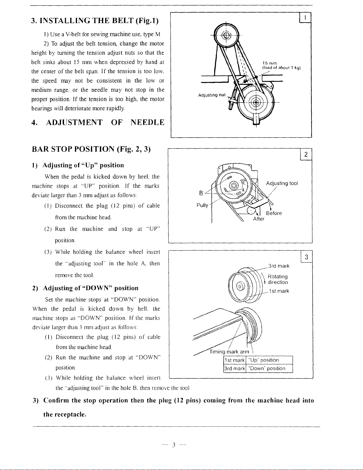
3. INSTALLING
1)
Use a V-belt for
2)
To
adjust the
by
height
belt sinks about
the center
the speed may not
medium
proper position.
bearings will deteriorate
turning the tension
of
the belt span.
range, or the
belt
15
nm1
be
If
the tension is too high, the motor
THE
sewing
when
needle
more
BELT
machine use, type M
tension,
adjust
depressed
If
the tension
consistent in the low or
may
rapidly.
(Fig.l)
change
the motor
nuts so that the
by
hand at
is
too low,
not
stop in the
4. ADJUSTMENT
BAR
1) Adjusting
machine stops at
deviate larger than 3 mm adjust as follows
2) Adjusting
When the pedal
machine stops
deviate larger than 3
STOP POSITION (Fig. 2, 3)
of"
Up" position
When the pedal is
"UP"
(l)
Disconnect the
fTom
the machine head
(2) Run the
position.
(3)
While holding the
the ''adjusting
remove the tool.
Set the machine stops
(I)
Disconnect the
machine
of
"DOWN" position
is
kicked
as
"DOWN"
111111
OF
kicked
tool''
adjust as follows
position.
plug
(12 pins)
and
balance
in
at
"DOWN"
down
position
plug
(
down
If
stop
the hole
12
pins)
by
wheel insert
by
If
NEEDLE
heel, the
the marks
of
cable
at
"UP"
A,
then
position.
hell. the
the marks
of
cable
B
Adjusting tool
/
_3rd
mark
\ Rotating
I\
direction
.---1 st
mark
2
3
from the machine head.
(2) Run the
position.
(3) While holding the balance wheel insert
the
3) Confirm the stop operation then the plug
machine
"adjusting tool"
and
in
stop
the hole
at
"DOWN"
8,
then remove the tool
(1
2 pins) coming from the machine head into
the receptacle.
-3-
Page 5
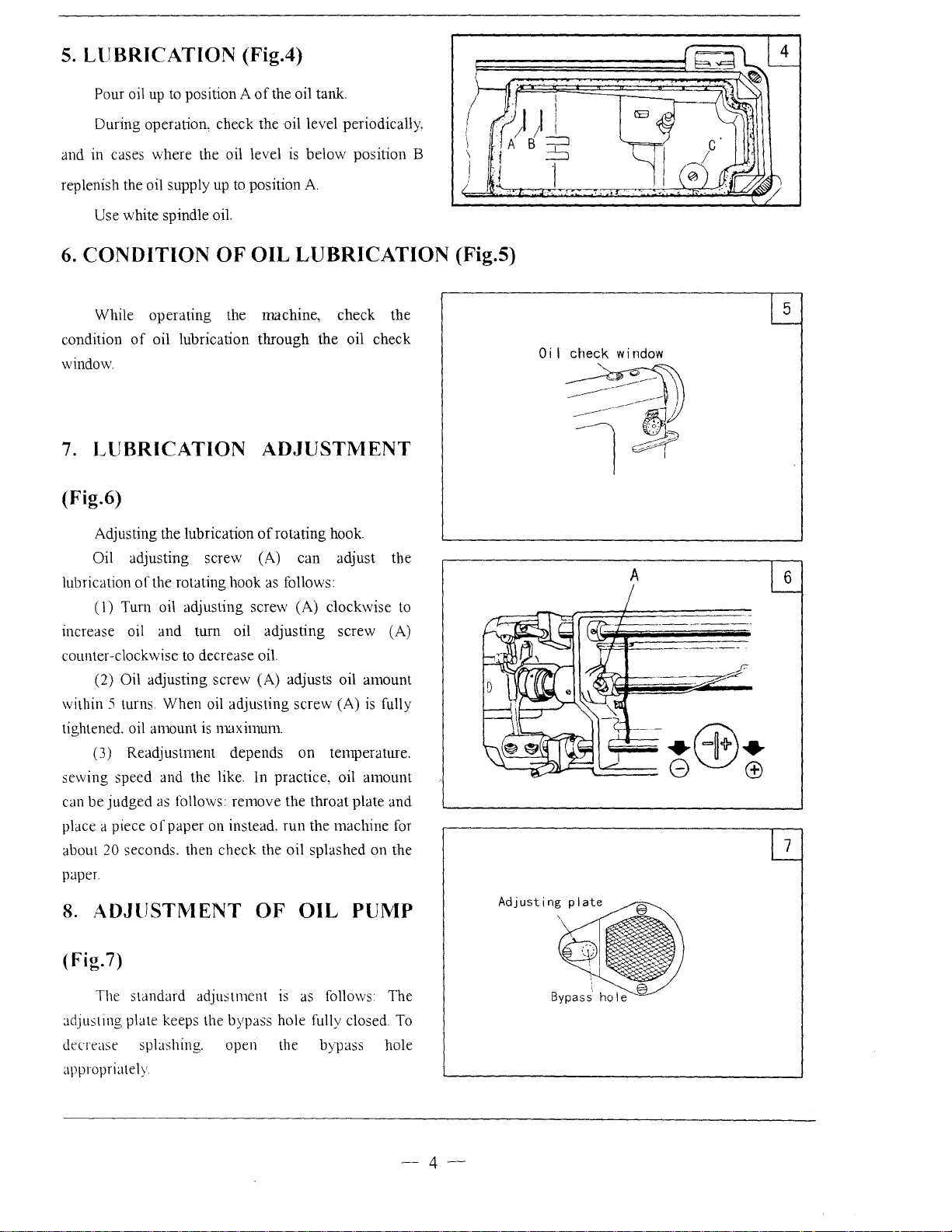
5.
LUBRICATION (Fig.4)
Pour oil up to position A
During operation, check the oil level periodically,
and in cases where the oil level
replenish the oil supply up to position
Use white spindle oil.
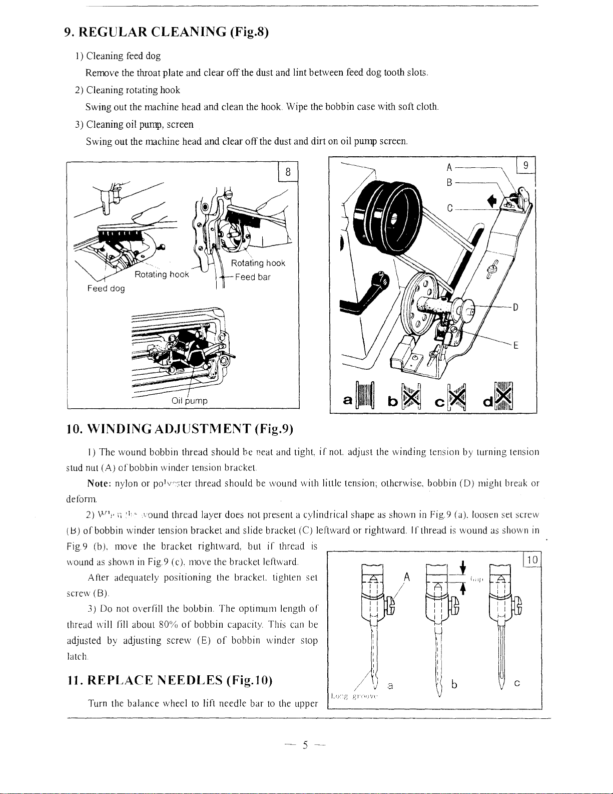
6.
CONDITION
While operating the machine, check the
condition
window.
7.
of
oil lubrication through the oil check
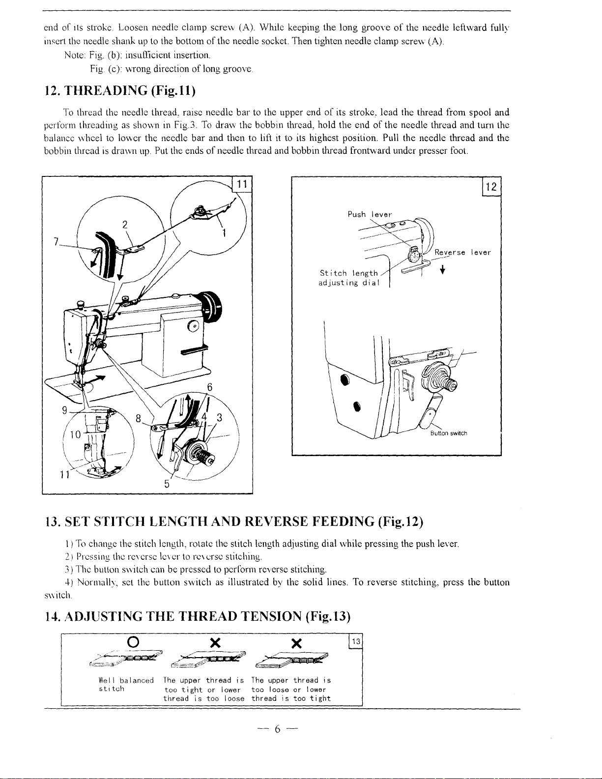
LUBRICATION
of
the oil tank.
is
below position B
A.
OF
OIL
LUBRICATION
ADJUSTMENT
(Fig.6)
Adjusting the lubrication
Oil adjusting screw (A) can adjust the
of
lubrication
(
1)
increase oil and
counter-clockwise
(2)
within
tightened. oil amount
(3) Readjustment depends
sewing speed and the like. In practice, oil amount
can
be
place a piece
about
20 seconds. then check the oil splashed on the
paper
the rotating hook as follows:
Tum oil adjusting screw (A) clockwise to
tum
to
decrease oil.
Oil adjusting screw (A) adjusts oil amount
5 turns When oil adjusting screw (A)
is
judged
as follows: remove the throat plate
of
paper on instead,
of
rotating hook.
oil adjusting screw (A)
is
maximum.
on
temperature.
run
the machine for
fully
and
(Fig.S)
Oi
I check
----------~-----~
~~
window
l-Jf
A
6
7
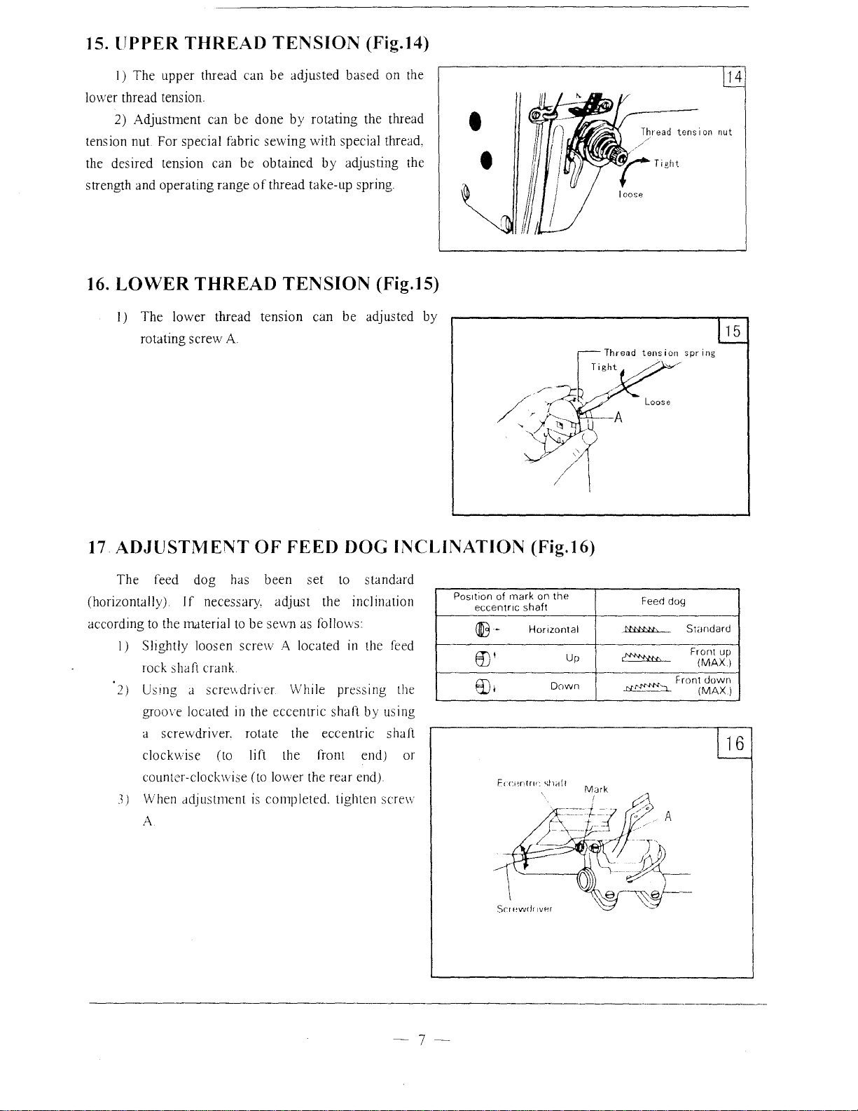
8.
ADJUSTMENT
OF
OIL
PUMP
(Fig. 7)
The standard adjustment
Jdjusting plate keeps the bypass hole fully closed. To
decrease
appropriately
spbshing.
open the bypass hole
is
as follows The
-4-
Page 6
9.
REGULAR
I) Cleaning feed dog
Remove the throat plate and clear off the dust and lint between feed dog tooth slots.
2)
Cleaning rotating hook
Swing out the machine head and clean
3)
Cleaning oil
Swing out the machine head and clear off the dust and dirt on oil
Feed dog
CLEANING
pump,
screen
(Fig.S)
the
hook. Wipe the bobbin case with soft cloth.
plll11p
screen.
A----,
B---__,
10.
WINDING
I) The wound bobbin thread should be Peat and tight.
nut
(A)
stud
Note: nylon or pol.r:;ter thread should be wound with little tension; otherwise. bobbin (D) might break or
defom1.
2)
(1:5)
of
Fig 9 (b). move the bracket rightward, but
\\Ound
After adequately positioning the bracket. tighten set
screw (B)
3)
thread
adjusted by adjusting screw (E)
latch
ofbobbin winder tension bracket.
vn;.
~~
bobbin winder tension bracket and slide bracket
as
shmvn
Do
not
\Viii
fill
ADJUSTMENT
·1
o vound thread layer does not present a cylindrical shape
in
Fig 9 (c). move the bracket leftward.
overfill the boubin. The optimum length
about
80'%
of
bobbin capacity This
of
(Fig.9)
(C)
if
thread
bobbin winder stop
can
is
of
be
if
not.
adjust the winding tension by turning tension
leftward or rightward. If thread
as
I
~
shown
in
Fig 9 (a). loosen set screw
is
wound
as
E
shown
in
10
11.
REPLACE N EEOLES
Turn the balance wheel
to
(Fig.1 0)
lift needle bar
to
the upper
)J
-s-
a
Page 7
end
of
1ts
stroke Loosen needle clamp screw (A). While keeping the long groove
insert the needle shank
Note Fig (b):
Fig (c) wrong direction
12.
THREADING
To
thread the needle tlu·ead, raise needle
perform threading as
balance wheel to lower the needle
bobbin thread is drawn
up
to the bottom
insu!llcient insertion.
(Fig.ll)
shown
in
up.
Put the ends
Fig.3.
of
the needle leftw·ard fully
of
the needle socket. Then tighten needle clamp
of
long groove
bar
to the upper end
To
draw the bobbin thread, hold the end
bar
and then to lift it to its highest position. Pull the needle thread and the
of
needle thread and bobbin thread front\vard under presser foot.
of
its stroke, lead the thread from spool and
scre'v\
(A)
of
the needle thread and turn the
'"~
12
-~~-----·~Reverse
Stitch
adj
13.
SET STITCH LENGTH AND REVERSE FEEDING (Fig.12)
len~,~~-
ust
i ng
Ji~l
lever
/I
I)
To
change the stitch length, rotate the stitch length adjusting dial while pressing the push lever.
2)
Press
1ng
the reYcrse lc\
3)
The button switch can be pressed to perl'orm reverse stitching.
4)
Normally, set the button switch as illustrated
S\Yitch
14.
AD.JUSTING THE
0
Wei I balanced
st1tch
cr
to rc\ crsc stitching.
THREAD
X
The
upper
tight
thread
or
is
too I oose
too
thread
TENSION
is
lower
The upper
too
thread
by
the solid lines. To reverse stitching, press the button
(Fig.l3)
13
is
loose
is
X
thread
or
too
lower
tight
-6-
Page 8
15.
UPPER
1)
The
10\ver thread tension.
2)
Adjustment
tension
the desired tension can
strength and operating range
16.
nut
LOWER
I)
The
rotating screw A
THREAD
upper
thread
can
be
For special fabric
be
THREAD
lower thread
TENSION
can
be
adjusted
done
by
rotating
sewing
obtained
of
with
by
thread take-up spring.
TENSION
tension
can
(Fig.14)
based
on
the
the thread
special thread,
adjusting the
(Fig.15)
be
adjusted
by
•
•
Thread
tension
~UHl~IA.~
//~/
14
nut
17
ADJUSTMENT
The
feed
(horizontally)
according
to
the material to
1)
Sllghtly loosen
rock shaft crank
2)
Usmg a scre\\driver
groove
a screwdriver. rotate the eccentric shaft
clockwise (to lift the front end) or
counter-clockwise (to lower the
3) When adjustment
A
dog
If
necessary,
located
OF
FEED
has
been
be
screw A located
in
the
is
set
adjust
sewn as follows:
While pressing the
eccentric
completed.
DOG
to
the inclination
in the feed
shaft
rear
tighten screw
INCLINATION
standard
by
using
end).
(Fig.16)
Pos1tion of rnark on
eccentnc
aB-
shaft
Honzontal
[)'
[),
the
Up
Down
Feed dog
t'NN,U,
~
J:i.!~'J
Standard
Front
Front up
(MAX)
down
(MAX)
-7-
Page 9
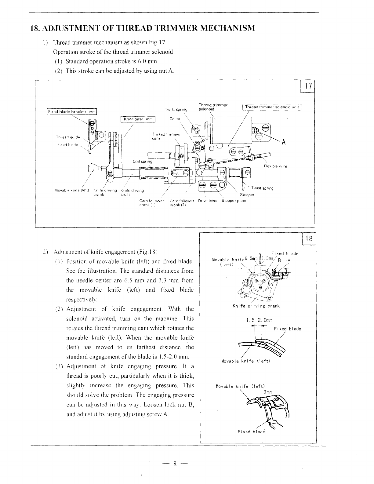
18.
ADJUSTI\1ENT
1)
Thread trimmer mechanism as shown
Operation stroke
(I)
Standard operation stroke is
(2) This stroke can be adjusted by using nut A
I FIXed
blade
bracket
~'
Thcead
gu1cle
hxerl
hi;:Hie "'-,
Movable
knde
OF
of
the thread tri1mner solenoid
un11/
),
~
§
·,
\left)
Knde
cr<Jnk
THREAD
Kn1fe base un1t I
/
/
drtvlng
Krn1e cinvrng
Shed!
TRIMMER
J\;1ECHANISM
Fig.l7
6.
0
mm
1 Thread
trnl1rner
solenotd
Twrs1
spnng
/
Collar
ur1d
I
A
Flexible
wtre
"'
"...TWISt
spnng
C:am
crank
follower
(1
I
(;:tl11
crank
follower
(21
Dr~ve
lever
Stopper
',.
plate
Stopper
2)
AdJustment
(I)
Position
Sec the illustration. The standard distances from
the needle
the
respective!~.
(2) Adjustment
solenoid activated, turn on the machine. This
rotates the thread trimming
movable
(left) has
standard engagement
(3) Adjustment
thread
slighth
should
can be adjusted in this
and adjust
of
knife engagement
of
mm
able knife (left) nnd fixed blade.
center
are 6.5 nnn and 3.3 mm from
movable
knife (left) and fixed blade
of
knife
knife (left).
moved
is
poorly cuL pmiicularly
to its farthest distance, the
of
knife engaging pressure.
(fig I R)
engagement
cam\\
When
of
the blade
With the
hich rotates the
the movable knife
1s
1.5-2 0 mm.
when
it
increase the engaging pressure. This
soh
c the problem
The
engaging pressure
\\ay: Loosen lock nut
it
b\ using adjusting sere\\
A.
is
If
thick,
B.
18
1.
5-2.0mrn
Fixed blade
a
Movable
Movable
knife
knife
(left)
(left)
3mm
-8-
Fixed
blade
Page 10
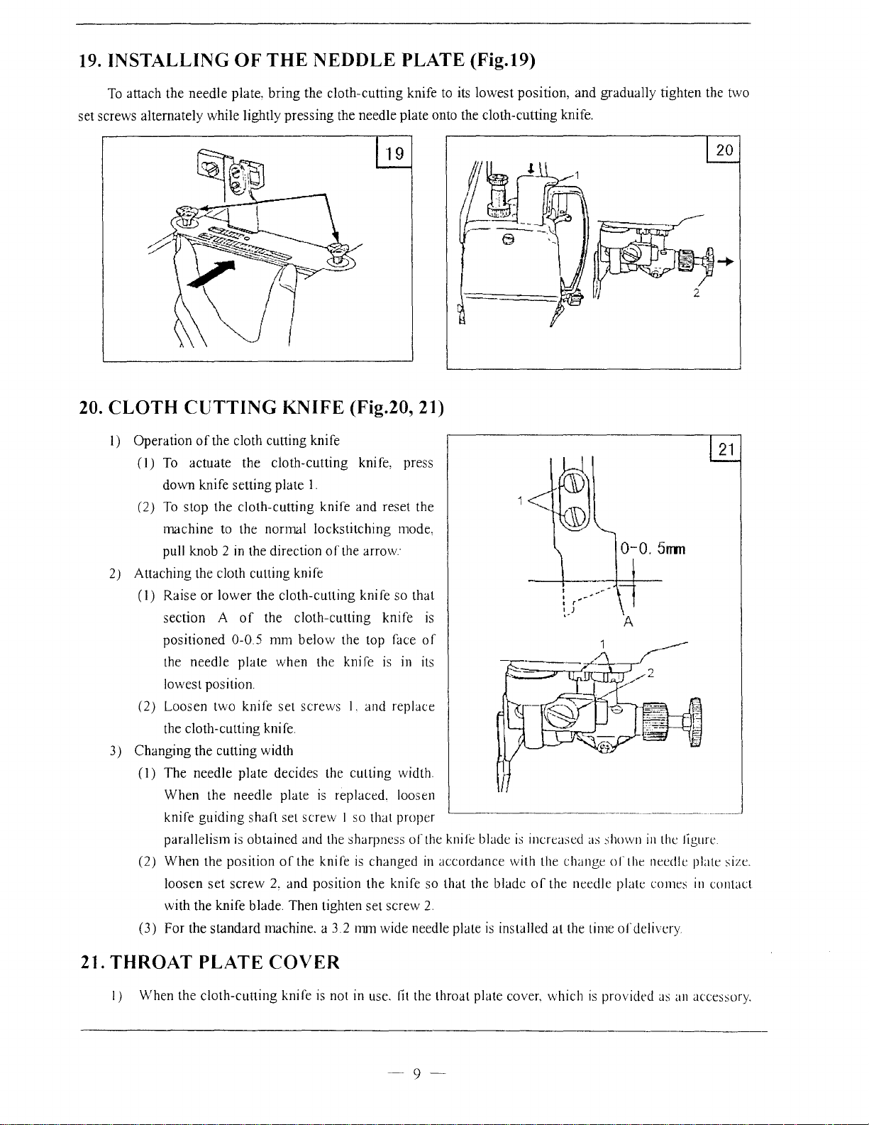
19. INSTALLING
To
attach the
set screws alternately while lightly
needle
OF
plate,
THE
bring
NEDDLE
the cloth-cutting knife to
pressing
the needle plate onto the cloth-cutting knife.
PLATE (Fig.19)
its
lowest
position,
and
gradually tighten the two
20. CLOTH
l)
Operation
(I)
(2)
2) Attaching the cloth cutting knife
(I)
(2)
3) Changing the cutting width
(I)
(2) When the position
(3) For the standard machine. a 3 2
CUTTING
of
the cloth cutting knife
To actuate the
down knife setting plate
To
stop the cloth-cutting knife and reset the
machine
pull knob 2
Raise
section A
positioned
the
lowest position.
Loosen two knife set screws I. and replace
the cloth-cutting knife.
The
When the needle plate
knife
parallelism
loosen
with the knife blade. Then tighten
to the normal lockstitching mode,
in
the direction
or
lower
of
0-0.5
needle
needle
guiding
is
set
screw
plate
plate
shaft
obtained and the sharpness
KNIFE (Fig.20, 21)
cloth-cutting
1.
the cloth-cutting knife so that
the
cloth-cutting
mm
below
when the knife
decides the cutting width.
set
screw
ofthe
2,
and position the knife so that the blade
knife, press
of
the arrow·
knife
the top face
is
is
replaced. loosen
I so that proper
knife
is
changed
set
screw
mm
wide needle plate
is
of
in its
'-------------~-----------~~---------------
of
the knife blade
in
accordance with the
2.
is
installed
is
increased as shown
change
of
the
needle
at
the time
in
the ligure
of
the needle plate size.
platt
of
delivery
comes
in
contact
21. THROAT PLATE
I) When the
cloth-cuning
COVER
knife
is
not in use.
fit
the throat plate cover. which
-9-
is
provided as an accessory.
Page 11
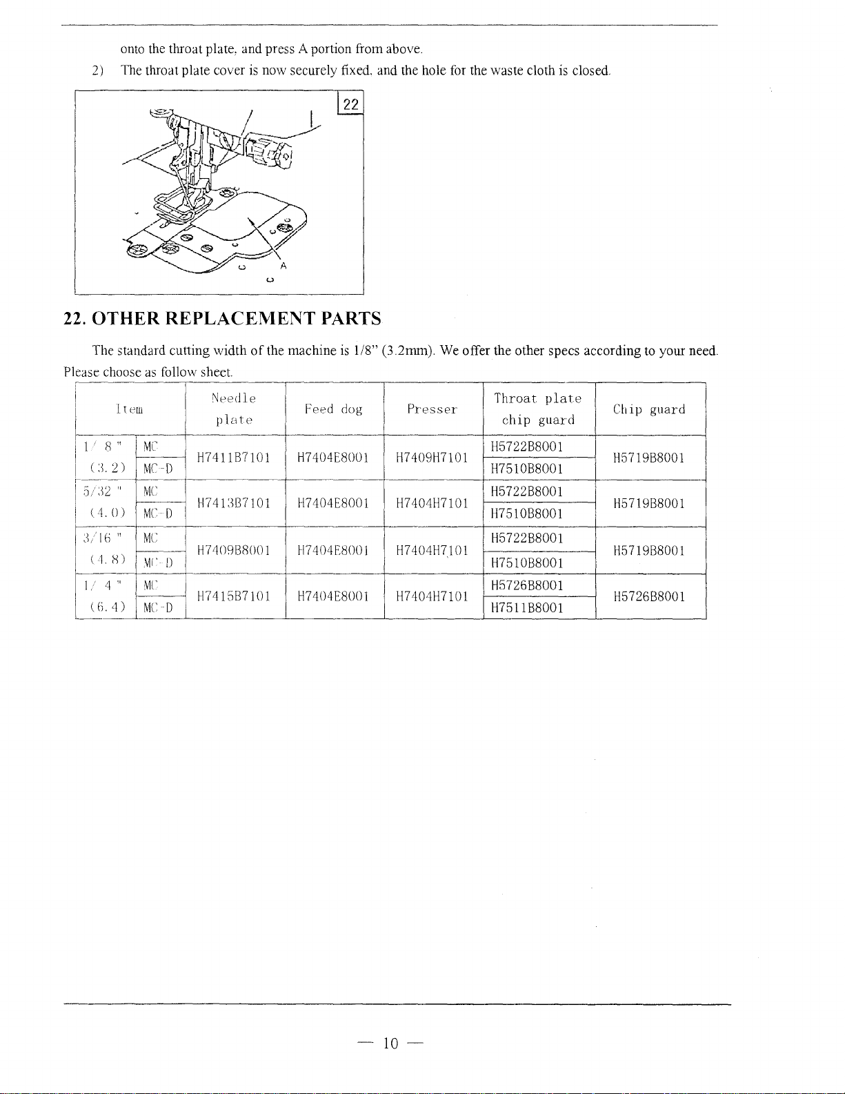
onto the throat plate, and press A portion from above.
2)
The throat plate cover
is
now securely fixed. and the hole
22
u
for
the waste cloth
is
closed.
22. OTHER
The standard cutting width
Please choose
I
I
I
ltew
REPLACEMENT
as
follow sheet.
I
4 "
4)
..
MC
MC-D
MC
MC
D
MC
'vH'
D
~JC
MC
D
11
. 8 "
1 u. 2)
'
I
-:
l2 "
I
::J.
•
i
(!.())
I
r~~(i
l (
1H)
I/
(
(i.
of
the machine
NPedle
plate
J-1741187101
1-1741387101
J-17409138001
f-1741587101
PARTS
is
1/8" (3.2mm). We offer the other specs according to your need.
Feed dog
H7404E8001
H7404E8001
H7404E800J
H7404E8001
Presser
J-174091-17101
J-174041-17101
f-174041-17101
H7404H7101
Throat
chip
H572288001
J-1751088001
J-1572288001
J-1751088001
J-1572288001
f-1751088001
J-1572688001
J-1751188001
plate
guard
Chip guard
J-1571988001
J-1571988001
J-1571988001
H572688001
-
10-
Page 12
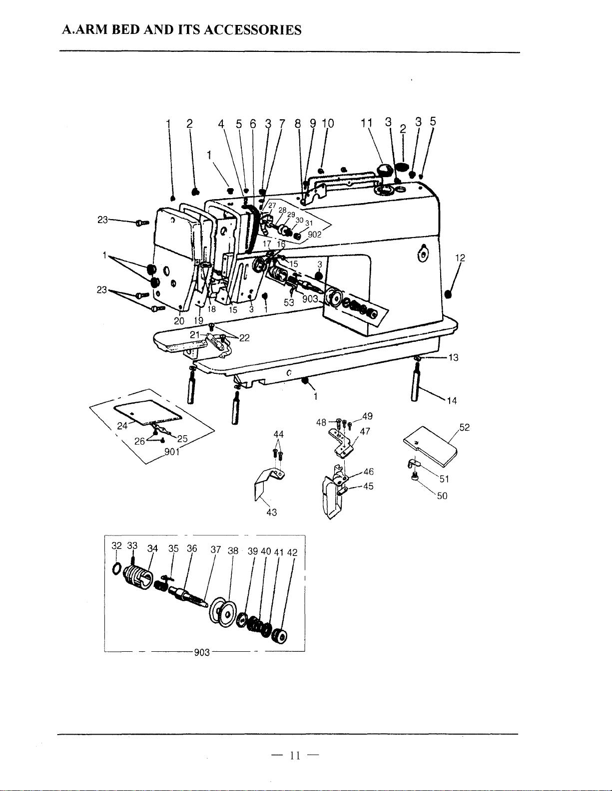
A.ARM BED AND ITS ACCESSORIES
1 2
23----o-
44
#
fZ
43
GJ
48~--A9
0
,,
47
•. I
)
~46
~
45
12
/
-
11-
Page 13

A.ARM BED AND ITS ACCESSORIES
Fig.
No.
A01
A02
A03
A04 HA300C2030
A05
A06
A07 HA100B2110
A08
A09
A10
All
Al2
Al3
Al4
Al5
Al6
A17
i\18
Al9
A20
A21
A22
i\23
A24
i\25
i\2(,
A27
i\28
A2<J
A3ll
/\31
i\32
/\33
A34
i\35
i\3(1
/\37
/\38
A3<J
i\40
A41
.'\42
A-13
Part No.
HA307B0674
HA307B0673 Rubber plug 2 2
HA300B2090
HA30082110
HA300C2020
HA700B2050
HA700B2060
HA300B2170
Hl210B0067
HA300B2100
H005008060 Spring washer
HA100B2220
HA106B0676
HA300B2080
HA100B2140
HA106B0675
H3010B0682
H5912mWOl
H741087101
HA30082190
HA300B2160
HA12480711
Hi\32480711
IIA124B0713
HA71080674
HA710B0673
I lA 11280693
I
lA 71080672
IIA71080671
IIA115B7011
HA11580708
IIA31 080703
I II\ 11580706
1-1/\11580701
HA11580709
IIA31 080705
I
!J'\31
OI30702
IL<\111580703
l-IA115I37010
I
IA31
OB070
!1571
<JB8()()
Rubber plug 6 6
Rubber plug
Set screw 1 1
Rubber plug
Thread take-up cover 1 1
Set screw
Thread guide
Set screw
Set screw
Oil
check window
Rubber plug
Leg
Set screw
Set screw
Thread guide
Thread guide
Face plate gasket
Face plate
Needle plate
Set
screw
Set
screw
Slide plate
Slide plate spring
Set screw
Pre-tension
Screw type tension stud
Disk for
Spring for pre-tension
Nut for pre-tension
0-ring
Set
screw
Thread tension regulating bushing
Tlu·ead
Thread tension stud
Thread tension releasing pin
Thread tension disc
Thread releasing disc
Thread ten::;ion spring
Stop disc
Thumb nut
1
1 Chip guide piate
thread guide
pre-tension
take-up spring
Description
u
~
00
-
'fl
u
0
5 5
2 2
1
1 1
1 1
6
1
1 1
3 3
3
2
1
1 1
1 1
1
1 1
1 1
2 2
3
1 1
1 1
2
1 1
1
2
I I
1
1 1
1 1
1
1 1
1 1
1
2 2
1 1
1 1
1
1 1
1 1
Q
c)
~
00
-0
'fl
0
u
0
SM11/64(40)x8
SM11/64(40)x5.5
1
SM11!64(40)x8
SM11/64(40)x9
6
1
GB/T93 6
3
SM9/64(40)x6
2
SM15/64(28)x6.8
1
1
SM11/64(40)x4.5
SM11/64(40)xlo
3
SM3/32(56)x2.2
2
SM1!/64(40)
I
2
SM1!/64(40)
1
SM9/64(40)x6
1
SM!/4(40)
1
1
Remarks
-12-
Page 14

A.ARM BED AND ITS ACCESSORIES
Q
u
I
~
00
......
<rl
0
u
0
1 1
2 2
1
I
2
SM118(44)x3.4
SM1/8(44)x3.4
1
1
1
u
Fig.
No.
Part No. Description
~
00
......
<rl
0
g
A44 H5727B8001 Screw 2 2 SM118(44)x3.4
A45 H5720B8001 Clip plate
A46
H5722B8001
H7510B8001 Chip funnel 1
A46
A47
H5723B8001 Chip funnel plate 1 1
HA300B2190 Screw 2 2
A48
H5727B8001 Screw 2
A49
A 50 H5720I8001
A51
H5721I8001 Spring for chip funnel cover 1 1
H5727B8001 Screw
A52
H3000B2130 Tirread guide 1
A53
A901 HA324B0071
A902 HA710B0067 Pre-tension thread complete
H30!3B0070 Tirread
A903
Chip funnel 1
Chip funnel cover 1 1
Slide plate complete 1 1
tension complete 1
Remarks
-
13-
Page 15

5
6
11
12 13
14
15
16
20
34
18
19
21
14
22
23 24
25
I
L~
I
,,,
Page 16

B.NEEDLE BAR AND THREAD TAKE-UP MECHANISM
Q
u
u
Fig.
No.
801 H5709C8001 Needle
802
803
804
805
806
807
808
809
810
811 HA104D0652 Rubber
812
813
813
814
815
816
817
818
819
820
821
822
1323
824
1325
826
B27
B28
132S)
830
B31
B32
1333
834
835
1335
836
837
838
839
840
841
Part No.
bar
H5710C8001 Thread guide
HAIOOC2170 Needle
HAIOOC2160 Needle I I
HA7311C606
HAIOOC2070
HAIOOC2060
H5705C7101
HA307C0662
HAIOOC2200 Slide block
HAIOOD2030
H5711C7101
H7504C7101
1-IA I OOC2020
HAIOOD2040
I-IAI08G0066
HAI05D0662
HAII3D2112
I-IAII3D2122
HA112D3012
H30211Cl06
H30211C406 Washer
HA7311C306
HA300D2020
HA306D0066
H30211C206
HA7311C506
HAI12D3013
fiAIOOD2110
HAI13D0691
HAIOOD21
IIA113D2222
HA113D2212
HA108C0663
HA710R0651
HA307D0671
I-L<\110D0672
HA700R0030
HA700ROOIO
HA700R0020
HA700R0040
HA700R0050
lO
clamp
Set
screw
Set
screw
Set
screw
bar
Needle
Set
Arm
Arm
Arm
Set screw
Arm
Collar for
Set screw
Bevel
Bevel
C-type ring
Feed and feed liiling eccentric
Set screw
Arm
Oil
Needle bearing
Crank rod for feed rock
Crank rod for feed lifting rock shalt
Vertical shall hushing (upper)
Vertical shaft
Vertical shalt bushing (lower)
Bevel
Bevel
Set
Driver
Driver
Set
Spacer 1
Speed
Speed
Spacer 2
Support spring
crank complete
screw
plug
shaft
bushing
shaft
shaft
shaft bushing (middle)
arm
gear
for
gear
for vertical shafl(upper)
shall hushing (right)
seal
gear
for vertical sha!t(luwer)
gear
for hook shalt
screw
screw
command
command
screw
shan
arm
disc 1
disc 2
(left)
shall
Description
shan
~
00
~
0
"'
C)
I I
I
I I
I I
I I
1 I
1 1
2
I I
2
1 1
1
4 4
I I
1 1
2 2
1 1
I I
1 1
1 1
1
3
1 1
1 1
1 1
1 1
1
1 1
1 1
1 1
1
1 1
8
1
2
~
00
~
0
"' u
u
C)
I
SMI/8(44)x4.5
SMll/64(40)xJ2
SMli4(40)x6
2
2
1
SM15/64(28)x
SM1/4(40)x4
I
SM9/64(40)x7
3
1
1
SMl/4(40)x7
8
1
SM 15/64(28)X
2
2
1
I
1
1
Remarks
10
12
-
15-
Page 17

B.NEEDLE BAR AND THREAD TAKE-UP MECHANISM
Cl
I
u
~
00
~
If)
0
~
1 G8/T894.1
SM11164(40)x8
3
1
1
Fig.
No.
842
843
844
845
846
847
848
8904
8905
8906
Part No.
HA700R0060
H007009300 C-type ring
HA300C2030 Set screw
HA703R0066 Detector bracket supporter
HA703R0067
HA700ROOOO
HA703R0065
HA104C0065
HA113D4021
HA113D4022
Washer 1
Washer 1
Driver complete
Detector complete 1
Needle
bar
Bevel gear for
Bevel gear for hook shaft complete
u
~
00
Description
link and thread take-up lever complete 1 1
arm
shaft complete
~
If)
0
u
C)
1 1
1 1
Remarks
30
-16-
Page 18

1
------------.
21
22
23
12
13
14 15
16
10
11
38
37
36
35
Page 19

C.NEEDLE BAR FEEDING MECHANISM
Fig.
No.
COl
C02
C03
C04 H3012D0693
cos
C06
C07 H7404D8001
C08
C09
C10
C11
Cl2
Cl3
C14
C15
C16
C17
C18
C19
C20
C21
C22
C23
C24
C25
C26
C27
C28
C29
C30
C31
C32
C33
C34
C35
C36
C37
C38
Part No. Description
HA304G0656 Set screw
H3012D0691
HA100B2110 Set screw 2 2
H3012D0692 Needle bar vibrating lever link pin 1 1
H5904D7101
H7405D8001
H3000D2160 Set
H3000D2170
HA300C2030 Set screw
H3000D2020
H3000D2030
H30612D113
H005005050
HA304G0656 Set screw
H3000D2110 Needle bearing
HA104G0654 Set screw
H005004040 Washer
H3000D2130
HA100B2110 Set screw
H3010D0672
H3010D0671 Rock shaft
H3009D0662
HA104G0012
H3009D0661
HA100B2110
HA105D0662
H3011D0681
H3010D0673
H3010D0674 Washer
H007009120
H3000B2110
H3000D2050
H3004D0651
HA304G0656
H30611D713
H3000D2040
Needle bar vibrating lever
Needle bar vibrating lever link
Needle bar support complete 1 1
Gasket for needle bar support 1 1
Fitting plate for gasket 1 1
screw 2 2
Needle bar support guide bracket 1 1
Needle bar support bushing 1 1
Needle clamp screw
Guide bracket for needle bar slide block
Washer
Felt
Rock shaft bushing (left)
Rock shaft driving crank pin
screw
Set
Rock shaft driving crank
screw
Set
screw
Set
Collar for rock shaft
Rock
shan
bushing (right)
C-type ring
Rubber plug
Crank rod for feed rock shaft
Feed rock
Set
Set screw
Eccentric
screw
shan
shan
driving crank
~
I
00
.-
Of')
0
g
1
1 1
1
2 2
1 1
1 1
1 1
1 1
1 1
1
1 1
1 1
2 2
1
1
1
1 1
1 1
1
2
1
1 1
1
1 1
1
1
1
1
1
1
Cl
I
u
::;E
I
00
..-
Of')
0
g
1 SM3/16(28)x
SM11/64(40)x5.5
1
SM9/64(
SM11/64(40)x8
SM11/64(40)x4.35
GBfr95
SM3/16(28)x15
SM1/8(44)x6
1
GBfr848 4
SM11/64(40)x5.5
1
1
1
SM3/16(28)x12
SM11/64(40)x5.5
1
SM1/4(40)x4
2
1
1
GBfr894.1 12
1
1
1
SM3/16(28)x15
1
SM1/8(44)x3. 9
1
1
40)x4. 5
5
Remarks
15
-18-
Page 20

11
2
3 4
12 13
-
:..c
5
161
~
~"
17
6
~
18
19 20
21
48
43
31
9
41
46 40
44
35 36
37
38 39
7
Page 21

D.ROT A TING
Fig.
No.
DOl
D02
D03
D04
DOS
D06 HA104G0011
Part
No.
HAI04G0656
H30311El06
HAI04G0654 Set
H7404E8001
HA705J0654
HOOK
Washer
Feed bar I 1
screw 2 2
Feed dog 1 1
for feed bar crank (eccentric) 1
Shaft
Feed rock shaft crank 1 1
D07 HA!04G0012 Set screw
HA300G2050
D08
H007009150
D09
DIO HA100G2040
HA7311C706 Feed rock shaft crank (right)
Dll
HA706CIIB2
Dl2
HA7311C806 Set screw
D13
Dl4
HA7311C606
HA305E0662 Set
DIS
Dl6
H3005E0066
HA700E2060
D17
1)]8
HA300E2050
))]'_)
HAIOOE2150 Set screw
])20
ll3004E0065
)
)21
HA104EOOI1
))22
11Al111E204
))23
I
fA
700E2030 Oil seal
IIA 704B0(>54 I look shall hushing (left)
I
>24
))25
11/\3041~0(>5
7041
IIA
I l25
I
!2(>
II A 71
0 I
Iii\
I
>27
>2X
I
>2'!
I
))\()
I
l31
IJ\2
I
!.\I
I J\4
7101
));\
7041l0(>53
I l.\305 I
lii\3i!5i·i!(>(>2 Set screw
11\3111·1)(>71
llo\ I
Ill
11.\31101·:2
11\.11)())'211
I l I 5 lli\31Jill•2040
II.\
I
>31,
/J\7
I
!.IX
I><'>
I
>411
>41
I
>4'
I
/114/·0(>54
II.\
/I)()(
//.\311(>1
I
J.\3115t
1/A/IJIII
II.\
/IIIII
I lA/
IIt
Feed rock shaft 1 1
C-type ring
Feed
rock shafl bushing 1 1
Feed rock shaft crank pin
Set screw
screw
Rotating hook complete
Bobbin
Rotating hook positioner
Bohhin case complete
Filter complete
Filter
Rotating hook shall
I
Rotating hook shall
~0(>5
I
t
~tWJ
I
·:om2
Thread
Set screw
immer
Rotating hook shall bushing (middle)
Collar
Ill!·
'00(>(>
rotating hook shaft
Rotating hook shall bushing (right)
I lil pipe
I
~i!i>72
J()() Plunger
()
l)lunger spring
I luiLk plate
ll>r
Set serew
i2070
1/ingc pin
Feed lilling
ill01>7
i1Jr,r,3
l'ccd lilling mck shall
Feed I ill ing rock shall bushing
i2/211
\Vashcr
i2130
i()(,X3
Sct scrcw
SHAFT MECHANISM
Description
cam
rotating hook shall
rm:k
shall crank (right)
u
~
I
00
~
<r)
0
u
c.J
I 1
4
2
1
I 1
2 2
1 1
I I
I I
I I
I I
1
1 1
I 1
1 1
1 1
I 1
1
1 1
1 I
l 1
I
1 I
I
l I
l l
l l
I
l l
I I
I I
I
Cl
I
u
~
00
-
<r)
0
u
c.J
SM118(44)x6
1
SM3/16(28)x12
4
GB/T894.1
2
1
SMI1164(40)x7
SM11!64(40)x12
SM15/64(28)x4.5
SMII/64(40)xJO
I
1
1
SM114(40)x10
2
I
15/M(2~)x4.5
SM
1
1
SMI5/M(2X)x10
l
SM11/64(40)x12
1
Remarks
15
-20-
Page 22

D.ROTATING HOOK SHAFT MECHANISM
Cl
C)
u
~
Fig.
No.
D43 H3009E0068
D44
D45
D46
D47
D48
D49
D50 HA104G0658 Hinge pin nut 1 1 SM3/16(32)
D51
Part No.
Feed lifting rock shaft crank (left)
HA108G0066
HA105D0662
HAIOOC2020 Set screw 2 2 SM15/64(28)x
HA112G0070 Feed bar link 1
HA100G2100
HAI04G0659 Hinge pin I I
HA300C2030 Set screw 1 1 SM11/64(40)x8
Collar for Feed lifting rock shaft
Set screw 4 4 SM1/4(40)x4
Set screw
Description
I
00
~
......
00
V")
......
V")
0
0
g
g
1 1
2 2
1
2 2 SM9/64(40)x6.5
Remarks
10
-21-
Page 23

E.STITCH REGULATOR MECHANISM
1 2
6 7 8 9
38 39
50
40
41
I ! I
42
i
46/
51
35
1817
16
~~-~~~
\
31
30
48
23
\r'
·.
··\
29 28
49 24
~
27
22
25 23
21
20
-22-
Page 24

E.STITCH REGULATOR MECHANISM
Fig.
No.
EO!
EO!
E02
E02 H3000F20!0
E03
E03
E04
E05
E06
E07
E08 HAIOOF2040
E09
EIO
Ell
Ell
E12
E12
E13
E14
E15
E16
E17
E17
E18
E19
E20
E21
E22
E23
E24
E25
E26
E27
E28
E29
E30
E31
E31
E32
E33
E34
E35
E36
Part No. Description
H!204E0651
H3000F2070
HA73!1C406
H1204E065I Feed regulator I
H3005F0651 Feed regulator I
H3000F2090
H007013040
H2204D0652 Pin
HA704B0655 Feed regulator bushing
HA700B2120
HA1!3F0684
HA115F0692 Spring for reverse feed lever crank
H3009F0663
HA115F0069
H3009F0066
Hf
113F3022
HAIOOF2110
HAI13F0683
HA309F0671
HA113F3021
H3008F0671
HAIOOF2130
HA800F2020
HA706C!IBI
HA706C!191
HA706C!192
HAIIIG0683
HA7311CE06
HA700C2040
H2000H2020
HA73!!CG06
HA7311CD06
HA73!1CC06
HA700C2050
HA7311CF06
H3000F2080
HA104F0654
HAI09F0674
HAIOOF2090
HAIOOF2140
HA700F2030
Connecting rod stud
Connecting rod stud I
Feed connecting link I
Feed connecting link I
Reverse feed link
Washer I I
Hinge pin for feed regulator
Rubber plug
Set screw
Spring for reverse feed lever crank I
Reverse feed lever crank
Reverse feed lever crank
0-ring
Washer
Set screw
Reverse feed lever
Reverse feed lever pin
Reverse feed lever pin
Set screw
Set screw
Link stud
Link (short)
Link (long)
Set screw
Link stud
Feed regulator shaft (right)
Set screw
Stitch length adjusting crank
Set screw
Set screw
Feed regulator shaft (left)
Link stud
Link stud
Set screw
0-ring
Spring for stopper pin
Spring holder
Stopper pin
u
~
I
00
..-
V")
0
g
I
I I
I I
I
I I
I
1
I 1
I
I I
I I
1
I I
1
I
2
2
3 3
1
I
2
I
I
I I
I
I
2
I
I
I I
I
Q
I
u
~
00
..-
V")
0
g
I
GB/T896 4
1
SM15/64(28)x8.5
I
1
I
SM3/16(28)x6.5
I
SMI5/64(28)
SMI5/64(28)x 13.5
I
I
2
2
SM!li64(40)x12
I
I
SM15/64(28)x14
2
I
SM9/64(40)x8.5
I
SM9/64(40)x6.5
I
I
SMI5/64(28)x!O
2
I
I
I
Remarks
-23-
Page 25

E.STITCH REGULATOR MECHANISM
u
;:;s
Fig.
No.
E37
E38
E39 HA7421F120 Dial 1 1
E40
E41
E42
E43
E44
E45
E46
E47
E48
E49
E50
Part No.
HA720F0681
HA720F0683 Stopper pin releasing lever
HA720F0684
HA720F0685 Bushing for dial screw
HA720F0686 Dial screw
HA720F0687 Coil spring 1
HAJOOC2190
HA7311CI06 Spring holder
H.A.7311CJ06
HA7311C706 Feed rock shaft bushing 1 1
HA7311C806
HA7311C606
HA706C11B2 Link stud 1 1
Feed regulator screw
Stitch length indicating plate
Set screw
Spring for feed regulator crank
Set screw 2
Set screw 2
Description
bar
I
00
V)
-
u
0
1 1
1 1
1
1
1 1
1
Cl
u
~
00
V)
-0
0
g
1
I
1
SM9/64(40)x8
2
1
I
SM11!64(40)x7
2
SM11164(40)x
2
Remarks
12
-24-
Page 26

F.PRESSER
FOOT
MECHANISM
25
24
23
22
17
15
14
13
2'
21
...
9
10
L9t8J
22
'\
1
8
3 1
7 6
5
1
12
11
-25-
Page 27

F.PRESSER FOOT MECHANISM
u
Fig.
No.
Part
No.
Description
~
00
~
.,.,
0
g
HA107H0663
F01
F02 HA107H0662 Set screw 2 2
F03 HA100H2050 Set screw 1 1
F04 HA306H0067 Knee lifter lever (right) 1 1
HA306H0671
F05
HA100H2080
F06
F07 HA110H0672
F08 HA100H2050 Set screw 1 1
HA305H6611 Tension releasing
F09
FlO HA7311Il06
H7404H7101 Presser foot complete 1 1
F11
HA100H2150
F12
HA704B0651 Presser bar bushing 1 1
F13
HA300H2110 Presser bar 1 1
F14
HA705I0661 Presser
F15
HA300H2080
F16
H7408H8001 Presser
F17
FUl HA100B2110
HA3411D308
Fl9
H3004G0651 Presser
F20
F21
HA300H2050
HAI07H0662
F22
HAIOOH2120
F23
HA309H0681
1'24
HAI17H0692 Lock nut
F25
F908 Hi\706!2011
Knee lifter rod 1 1
Knee lifter connecting rod 1 1
Pin for spring
Spring
for knee lifter lever
cam
Knee lifter lever (left) 1 1
screw 1 1
Set
bar
lifting
cam
Oil
seal for presser bar litling cam 1 1
bar
lifter
screw
Set
Set screw 1 1
bar litling bracket I
Presser
bar spring 1 1
Set
screw 1 1
Presser
bar guide 1 1
Pressure
Presser
regulating thumb screw 1 1
bar litling lever complete 1
1
1 1
1 1
1
1
1
1 1
0
u
~
00
~
.,.,
0
u
tJ
SM3/16(28)x3.5
SM15/64(28)x13.5
1
SM15/64(28)x135
SM9/64(40)x11
1
1
SM11/64(40)x5.5
1
SM 15/64(28)
1
SM3/16(28)x3.5
1
Remarks
x7
-26-
Page 28

G.KNIFE
2~
MECHA
1
NISM
7 6 5
~
1
-27------------
~
Page 29

G.KNIFE MECHANISM
Fig.
No.
GO!
G02
G03
G04
G05
G06
G07
G08
009
010
011
012
013
014
015
016
017
018
019
0:.?.0
021
022
023
0:.?.4
025
U26
U27
()28
02<)
ll30
l
ll32
l
l
l i35
l
037
()38
l
l
Part
No.
H7405F8001
H7406F8001
H7407F8001
1-13200!2030
HA104J6510
H5707F8001 Spring
HA104F0654
HAIOOE2150
HA100C2170
H5709F8001
H5710F8001 Knife
H5711F8001
H5733F8001
H5712F8001
H7409F8001
l-1005004050
H5735F8001
H5715F8001
H5716F8001
1-1007013015 Stop ring
H5717F8001
H5718F8001 Pin
H5719F~W01
H5720F8001
H5721F8001
HA104C0659
H5722F80lll
I-I5723F800 I
1130211 C206
1!5724F8001 Knife
115
i31
133
134
13(,
i3<J
140
725F800 I
l-15726HOOI Pin
115727F8001
IIA100C2l<JO
l!A
I OOC2200 Slide
115728F8001
H5729F8001
H5730F8001
115731F8001
115732F8001
Knife
positioning
Screw
Spring
Washer
Nut
Screw
Screw
Screw
Washer
Knife
holder
Screw
Knife
driving
Guide
stud
for
Washer
Screw
Knife driving
Spring
Knife release
Knife
driving
Bushing
Knife
driving
Screw
Knite
driving
Knite driving
needle
Knite
cam
plate
Thrust
Slide
block
Screw
block
Knob
Nut
Cap
Spring
K.nite
driving
block
knife
rod
lever
rod
stud
stud
rod
bearing
guide
block
Description
plate
Asm.
driving
clutch
pin
clutch
pin
connection
stud
guide
u
~
oO
V)
-
0
g
1 1
2 2
2
2 2
2 2
1 1
1 1
1 1
2 2
1 1
1 1
1 1
1
1 1
1
2 2
2 2
1
1 1
2
1
1
1
1
1
1
I
1
1 1
1 1
1 1
1
1 1
2
1 1
1 1
2 2
1
1 1
I 1
Cl
I
u
~
I
00
V)
-
0
g
SM9/64(40)x5
2
SM
15/64(28)
SM
15/64(28) X 10
SM11164(40)x9.5
SM1/8(44)x4.5
SM11/64(40)x8
1
1
GB!f848
SM3/16(28)x9
1
GB!f896
2
1
1
1
1
1
SM9/64(40)x6
1
1
1
1
SM!1/64(40)x8
2
1
Remarks
5
1.5
-28-
Page 30

61
60
18
7-----
---CG~-
~
~-5
3
4
40
39
54
38
37
36
34
15
35
7
32
33
Page 31

H.
THREAD TRIMMER MECHANISM
Fig.
No.
Part No.
Description
()
~
00
.-
on
0
g
Cl
u
~
00
.-
on
0
g
Remarks
HA713N0070 Flexible wire
HOI
Thread
HA713N0701
H02
HA712N0698
H03
HA712N0695
H04
HA712N0697
H05
HA712N0696 Collar for
H06
HA710N0683
H07
HA712N6910 Flexible wire support plate
H08
HA712N0699
H09
HA712N6911
HlO
HA712N6912
H11
HA712N6913
H12
H003002050
H13
HA7511N212 Solenoid
H14
HA700N0080 Set screw
H15
HA712N0692
H16
HS900!1406
H17
HA7641B319
H18
HA7121N604
H22
HA7121NI04
H23
HA7121N404
H24
HA7121N304 Set screw
H25
H2(i
H3000H2030
11A
H27
1!2X
[
[2()
1130
1131
[[32
1133
r
134
1135
I
f3(,
1137
lf3X
1139
1140
1141
1142
r
143
lf44
1145
114(J
7121 N704 Nut
I IA
7221
N206
HA7221NIO(,
!lA
706N0663 Nut
IIA70'JN0671
HA700NOIIO
IIA715N0711
I lA 7 ION06X2
I
fA
7 411 N I I 0
f lA 700N0040
I fA700N0050
11750XIXOOI
I
175()(,1XOO
IIA
71
IIA7111N404
IIA7111N304 Nut
IIA719B7011
I
!75071XOO
!IA704NIII4
HA704NIII3
I
I I N204
I
trimmer
Thread
trimmer
Stud
screw
Trimmer
Stopper
Set screw
Flexible wire
Set screw
Wire
Wire
Thread
P-type
Terminal pin
Set screw
Bracket for fixed
Thread
Fixed blade
Crank
C'rank roller
Stopper
Coil spring
Collar
Lever stopper plate
Screw
Coil
Bushing
Knife
Knife holding
Set screw
Rod
Set screw
Knit~
Set screw
Washer
driving
stud
nut
holder
nut
bracket
trimmer
screw
tinger
screw
block
with
spring (leH)
driving
driving
complete
driving lever
driving
lever
screw
presser
solenoid
blade
screw
shall
bracket
crank
lever 1
spring
stud
saddle
1
1
1
1
1
1
SM
15/64(28)
1
SM11/64(40)x4
1
I
SM118(44)x7
2
1
2
GB/T6170
1
SM15/64(28)x12
4
1
M4x6
3
2
SM9/64(40)x8.5
1
1
1
SM9/64(40)x5
1
I
SM9/64(40)
I
I
1
SM3/16(28)
I
1
I
1
1
SM
I
1
1
1
I
2
I
2
I
I
3
1
15/64(28)x23
SM11!64(40)x6.2
SMII/64(40)
SMI1!64(40)x11
SMI/8(44)x5.2
M5
A
-30-
Page 32

H.THREAD
Fig.
No.
H47 HA704N1112 Knife holding bracket saddle (left)
H48
H49 HA7111N704
HSO
H51
H52
H53
H54 HA7311CH06
H55 HA113F0684 Set screw 2 SM15/64(28)x8.5
H56
H57 HA7311C606 Set screw 2
H58
H58
H59
H59
H60 HA300B2170
H61
H909 HA712N0069
Part
HA7111N804
HA300C2030 Set screw
HA7311CC06
HA100E2150 Screw
H007013040 Washer
HA105D0662
H5904H7101 Thread tension releasing bracket complete I
H5905H8001 Thread tension releasing bracket 1
HAIOOH2060 Thread tension releasing pin
H3000H2080 Thread tension releasing pin 1
HA708P0668
TRIMMER
No.
Movable knife (left) 1
Set screw
Set screw
Set screw
screw
Set
Screw
Cord holder
Solenoid bracket complete 1
MECHANISM
Description
Q
u
u
~
00
~
00
V)
-
V)
0
-
0
g
u
C)
1
2 SM11/64(40)x5.5
6
2 SM9/64(40)x6.5
1
2
1
1
1
1
1
Remarks
SM11/64(40)x8
SM11/64(40)x10
GB/T896 4
SM9/64(40)x8
SM114(40)x4
SM11164(40)x12
SM11/64(40)x9
-31-
Page 33

I.
TOUCH BACK AND
DETECTOR
MECHANISM
25
4 5
. I f
~li~~
9
27
1
-32-
13
Page 34

I.
TOUCH BACK AND DETECTOR MECHANISM
Fig.
No.
IOl
J02 HA700Q0030 Cord holder
I03
!04
105
106
I07
I07 HA108B0681
I08
I08 HA108B0682
!09
110
Ill
112
113
!14
!15
Il6
117
118
!19
12(;
!21
!22
!23
!24
!25
!26
!27
!28
!29
130
Part No. Description
HA300B2170 Screw
H2611E8001 Solenoid
HA712Q0693 Tie-in
HA700Q0010 Pin
H2206I0672
H2609E0671
H2609E0672
HA712N069l
H2204G0651 Screw
H2204G0652 Stop ring
HA705Q0065
HA700Q0050
HN00B2170
H5911J800l
HA7221P508
HA70400657 Rubber plug
HA70400659 Screw
HA.
70400654
H2205I0661
HA70400021 Touch switch complete
H007013030
HA70400653 Spring
HA7641B319
HA7641B319
HA300C2030
H007013040 Stop ring
HA70406510
HA70400655
HA70400658
Wasl~er
Arm
side cover 1
Arm side cover
Gasket for
Gasket for
Link stud 1
Ground wire assy.
Cord holder 1
Screw 2
Bracket for touch switch 1
Screw
Plate spring
Bracket for touch switch
E-type ring
Cord assy.
Terminal pin
Screw
Screw
Micro switch
Insulator seet
arm
side cover
arm
side cover 1
-
u
::'E
I
00
......
V)
0
g
1
0
u
~
00
......
V)
0
g
4
3
1
1
1
1
1
SM15/64(28)x7
1
1
1
SM11!64(40)x9
M3x5
2
1
M2x4
1
1
1
1
GB/T896 3
2
1
3
5
SM11/64(40)x8
4
GB/T896 4
2
M2x8
2
1
1
""'
Remarks
-33-
Page 35

J.OIL LUBRICATION MECHANISM
')
1
L.
,,__ _ _,...5
,
___
_,~
G
22
8
15
9
14
13
'
-34-
Page 36

J.OIL LUBRICATION MECHANISM
Fig.
No.
Part No. Description
u
:::2
ob
.-
V1
0
g
~
u
:::2
ob
.-
V1
0
g
Remarks
101
HA100H2150
102 H3004L0065
H3000L0020 Oil filter holder 1 1
103
H3006L0065 Oil return tube complete 1 1
104
HA116I0068
105
106 HA11610682
HA100I2010
107
HA100I2090 Set screw
108
HA100I2030 Set screw
109
HA300I2050 Set screw
110
HA100I2050
Ill
HA100I2070
112
J13
HA111I0065
HA700L0030
114
115
HA100I2020
HA707L0065
116
HA11310661
117
HA300I2030
118
HA300E2030
119
HA100E2060
.120
HA305G0664
121
H3000E2050 Oil wick
122
123
HA300C2030
H3000L0030
124
Screw
Oil
wick fitting plate complete 1 1
Arm
shaft oil tube complete 1 1
Arm
shaft oil tube connector
pump
Oil
Spring washer 1 1
Oil
adjusting plate 1 1
Oil pump screen complete
Oil
pump fitting plate
pump impeller
Oil
Oil
pipe for hook shaft complete
Oil pipe for hook shaft connector
Oil
return tube holder
adjusting screw
Oil
adjusting spring
Oil
Oil wick
screw
Set
Oil
pipe holder
2 2
1 1
1
3 3
1 1 SM1!8(44)x6.5
3 3
1 1
1 1
1
1 1
1 1
1
1 1
1 1
1
1 1
1
1
SM9/64(40)xll
1
SM11164(40)X13
SM1/8(44)x13
1
1
15/64x28/12
1
SM11/64(40)x8
1
1
-35-
Page 37

K.ACCESSORIES
44 9
~
~~rr~--2
7
•
~5
•
43
~
12~
11~
L~4~~
19
42
~3
~4
13
47
-----------
.
,_
__
,
~51
50
-36-
Page 38

K.ACCESSORIES
Fig.
No.
Part
No. Description
u
:::E
'
00
~
0
"'
g
Q
u
~
00
.-
"'
0
g
Remarks
KOl
HA100J2120
K02
HA704S0653 Hexagon socket screw key 2 1 1
K03
HA300J2230 Washer
K04
H801045200 Wood screw
KOS
HA300J2200 Screw
K06
HA300J2210
K07
HA704S0654
K08
HA100J2110 Oil
K09
HA307J0067 Hinge with rubber cushion
K10
HA300J2050
K11
HA300J2060 Head cushion (small)
K12
HA305J0666 Belt cover
K13
K14
HA300J2280
K15
HA300J2250
HA305J0662 Belt cover complete
Kl6
H003002040 Nut
Kl7
HA305J0665 Belt cover
Kl8
HA707S0068 Thread stand complete
Kl9
HA706S0067
K20
HA300J2190
K21
HA300J2130
K22
HA106J0661
K23
HA104J0654
K24
HA104J0653
K25
HA104J0652
K26
HA104J0655
K27
HA300J2160
K28
HA104J0657
K29
HA104J0658
K30
HA104J6510 Nut
K31
HA104J0659 Set screw
K32
H007013090 E-type ring
K33
H5703I7101
K34
H7504K7101
K34
HA106J0663
K35
HA300J2180
K36
HA106J0662
K37
HA106J0667
K38
HA106J0666
K39
HA106J0665
K40
HA106J0668
K41
HA300J2170 Oil tank
K42
Magnet block
Hexagon socket screw key 3
driver (Size M)
screw driver (Size S)
Speed
command disc adjusting plate 1
with oiler
Head cushion (large) 2 2
Set
screw
Screw
Bobbin winder complete
Head cover
driver (Size L)
Screw
Knee lifter lifting rod
Gasket for oil reservoir (small)
Seal
washer
Oil drain screw
Gasket for oil reservoir (large)
Knee lifter shaft
Knee lifter spring
Knee lifter
Oil reservoir
Oil reservoir
Knee lifter coupling joint
Bolt
Knee lifter bell crank
Screw
Gasket for Knee lifter plate
Knee lifter plate
Pad for knee plate
1 1
1 1
4
4
4 4 GB/T99 4.5x20
1
1
1
1
1 1
1
1
2 2
1 1
2 2 SM15/64(28)x8
1 1
1 1
1 I GB/T6170 M4
'
1
1 1
1 1
1 1
1 1
1 I
1 1
1 1
1 1
1 1
1 1
1 I
1
2
2 2
1 1
1
1 1
2 2
1 1
1 1
1 1
1
1 1
1 1
M4xl2.5
1
SMS/16(28) X I 0
1
2
SMS/16(28)
SM15/64(28)x28
GB/T896 9
1
SM5!16(18)x16
SM15/64(28)X8
1
-37-
Page 39

K.ACCESSORIES
Fig.
No.
K43
K44
K45
K46
K47
K48
K49
K50
K51
K52
Part
No.
HA115B0706 Thread take-up spring 1
HA300J2310
HA700E2060
HA300B2170
H5709I8001
H801045200 Screw
H5704I8001
H5705I8001
H801045200 Screw
HA1JOD0672
Needle
Bobbin 4
Screw
Bracket 1
Waste material chure(large) 1
Waste material chure(small) 1
Screw 1
Description
u
~
00
...-<
0
"'
~
1
2
3
4
Q
u
~
00
.--<
0
"'
~
1
1
4
SM11!64(40)x8
2
1
GBfT99
3
1
1
GBfT99
4
SM15/64(28)x12
1
Remarks
4.5x20
4.5X20
I
-38-
Page 40

SHANGHAI HUIGONG
N0.3
SEWING MACHINE FACTORY
ADD: 1418, Yishan Road, Shanghai,
China
Zip Code: 201103
Overseas
Business:
TEL:
86-21-64853303 FAX: 86-21-64854304
E-mail:highlead@online.sh.cn http://www.highlead.com.cn
The
description covered
in
this
manual
is subject to change for improvement
of
the commodity without notice
2004.3. Printed
 Loading...