

Highlead GC0518 User Manual
Purchasing
Copy
Dept
HIGH
GC0518
HIGH SPEED NEEDLE BAR FEED
WITH
Instruction
AUTOMATIC THREAD
LEAD
SERIES
Manual
LOCKSTITCHER
TRIMMER
Parts
SHANGHAI
HUIGONG
N0.3
Catalog
SEWING
MACHINE
FACTORY


CONTENTS
1.
PRECAUTIONS BEFORE STARTING OPERATION
2. MAIN SPECIFICATIONS
3. INSTALLING
ADJUSTMENT OF NEEDLE BAR STOP POSITION
4.
LUBRICATION
5.
CONDITION OF
6.
7. LUBRICATION ADJUSTMENT
8. ADJUSTMENT OF
9.
REGULAR
THE
..........................................................................................................
OIL
CLEANINp
10. WINDING ADJUSTMENT
11. REPLACE NEEDLES
THREADING
12.
13.
SET STITCH LENGTH
ADJUSTING THE THREAD TENSION
14.
15. UPPER THREAD TENSION
LOWER THREAD TENSION
16.
ADJUSTMENT OF FEED DOG INCLINATION
17.
18. ADJUSTMENT OF THREAD
PARTS
A.
B.
C.
D. ROTATING
CATALOG
ARM BED AND IT'S ACCESSORIES
UP
SHAF'f MECHANISM
FEEDING NEEDLE MECHANISM
E. STITCH
F.
PltESSElt F'OOT.,MEC.HANISM
G
KNIFE~CTUATINGI'ECHANISM
.•
H.
WIPEil MECHANISM
............................................................................................................
BOOK
.
1"··
L~GTH
• • ~ '!'
<·
•. : --,:"
REGULATOR MECHANISM
;·
::;,...-.~---~
I. TOUCH BACK MECHANISM
J. OIL LUBRICATION MECHANISM
K.
ACCESSORIES;
.........................................................................................................
..............................................................................................
BELT
.............................................................................................
LUBRICATION
..............................................................................
....................................................................................
OIL
PUMP
.......................................................................................
.............................................................................................
.............................................................................................
...................................................................................................
AND
REVERSE FEEDING
...........................................................................
..........................................................................................
.......................................................................................
TRIMMER
MECHANISM
................................................................................
..............................................................................................
.................................................................................
SHAFT MECHANISM
......................................................................
.....................................................................................
...............................................................................
................................................................................................
.......................................................................................
................................................................................
.........................................................
.........................................................
............................................................
..................................................................
......................................................
...............................................................
2
2
3
3
4
4
4
4
5
5
5
6
6
6
7
7
7
8
9
12
l5
17
20
23
25
28
30
33
35
-1-

1.
PRECAUTIONS
1)
Safety Precautions:
(
1)
When turning the power on, keep your hands and fingers away from the area around/under the needle
and the area around the balance wheel.
(2) Power must
(3) Power must
the machine, or when replacing.
(
4)
Avoid placing fingers, hairs, bars etc., near the balance wheel,
or motor when the machine is in operation.
(5) Do not insert fingers into the thread take-up cover, under/around the needle, or balance wheel when the
be
be
BEFORE
turned off when the machine is not in use, or when the operator leaves the seat.
turned
off
when tilting the machine head, installing or removing the
STARTING
OPERATION
"V"
belt, bobbin winder balance wheeL
"V"
belt, adjusting
machine
(6)
If
devices.
2)
Precautions before
(1)
If
(2)
If
(3) When a new sewing machine is first turned on, verifY the rotational direction
the power
( 4)
VerifY
3) Precautions for
(1) Avoid using the machine at abnormally high temperature ( 3 5
lower) .
(2) Avoid using the machine in dusty conditions.
2.
MAIN
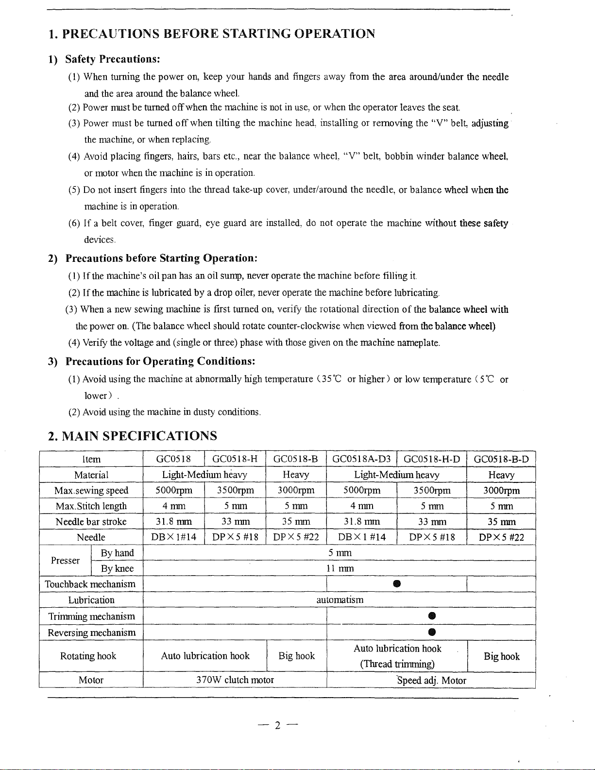
Item
Material
Max. sewing speed
Max. Stitch length
Needle
Presser
Touchback mechanism
Trimming mechanism
Reversing mechanism
bar
Needle
Lubrication
Rotating hook
Motor
is
in operation.
a belt cover, finger guard, eye guard are installed,
Starting
the machine's oil
the machine is lubricated
on.
(The balance wheel should rotate counter-clockwise when viewed from the balance wheel)
the voltage and (single or three) phase with those given on the machine nameplate.
pan
Operating
Operation:
has
an
oil sump, never operate the machine before filling
by
a drop oiler, never operate the machine before lubricating.
Conditions:
do
not operate the machine without these safety
OC
or higher) or low temperature ( 5
SPECIFICATIONS
GC0518 GC0518-H GC0518-B GC0518A-D3
Light-Medium heavy Heavy
3000rpm
5mm
35mm
DPX5
#22
5mm
11
automatism
5000rpm
4mm
31.8
DBX
mm
stroke
By hand
By knee
5000rpm 3500rpm
4mm
31.8
mm
DBX
1#14
Auto lubrication hook Big hook
5mm
33mm
DPX5
370W clutch motor
#18
it.
of
the balance wheel with
GC0518-H-D
Light-Medium heavy
3500rpm 3000rpm
5mm
mm
1 #14
33mm
DPX5#18
•
•
Auto lubrication hook
(Thread trimming)
'Speed adj. Motor
•
OC
or
GC0518-B-D
Heavy
5mm
35mm
DPX5
#22
Big hook
-2-
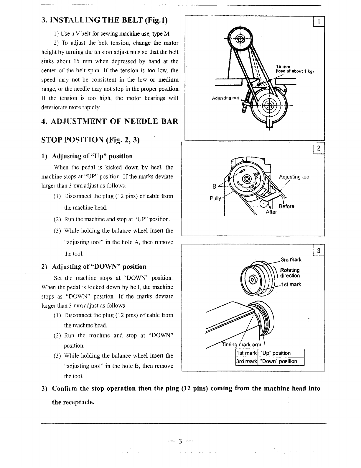
3. INSTALLING
1)
Use a V-belt for sewing machine use, type M
To
adjust the belt tension, change the motor
2)
by
height
sinks about
center
speed may not be consistent in the low or medium
range, or
If
deteriorate more rapidly.
4.
turning the tension adjust nuts so that the belt
15
nun when depressed
of
the belt span.
the
needle may not stop in the proper position.
the tension
is
ADJUSTMENT
THE
If
too high, the motor bearings will
BELT
the tension is too
OF
NEEDLE
(Fig.l)
by
hand at the
low,
BAR
the
STOP
1) Adjusting
machine stops at
larger than 3
2)
When the pedal
stops
larger than 3 mm adjust
POSITION
of
When the pedal
"UP" position.
mm
adjust
(I)
Disconnect the plug (
the
machine head.
Run
(2)
(3) While holding the balance wheel insert the
Adjusting
Set the machine stops at "DOWN" position.
as
(1) Disconnect the plug (12 pins)
the machine and stop at "UP" position.
"adjusting tool" in the hole
the
tool.
of
is
kicked down
"DOWN" position.
(Fig. 2, 3)
"Up"
position
is
kicked down
as
follows:
"DOWN"
as
follows:
by
If
the marks deviate
12
pins)
of
A,
then remove
position
by
hell, the machine
If
the marks deviate
of
heel, the
Adjusting tool
cable from
3
3rd mark
cable from
the machine head.
(2) Run the machine and stop at
position.
(3) While holding the balance wheel insert the
"adjusting tool" in the hole
the
tool.
3) Confirm the stop
operation
"DOWN"
B,
then remove
then
the plug (12 pins) coming from
the receptacle.
-3-
the
machine
head
into
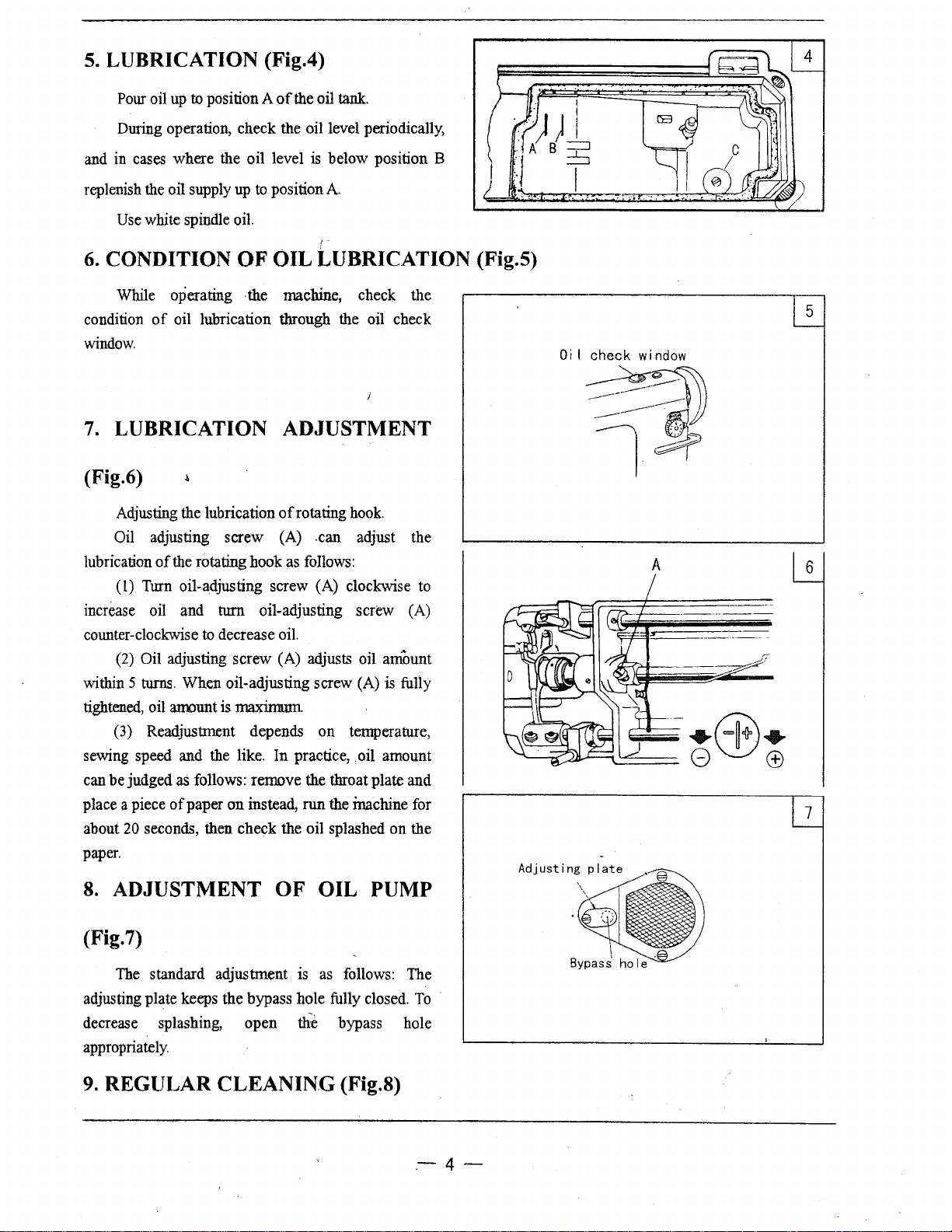
5. LUBRICATION (Fig.4)
Pour oil
During operation, check the oil level periodically,
and in cases where the oil level
replenish the oil supply
Use
6. CONDITION
While operating ·the machine, check the
condition
window.
up
to position A
white spindle
of
oil lubrication through the oil check
of
the oil
tank.
is
below position B
up
to
position
oil
OF
OIL LUBRICATION (Fig.5)
A.
7. LUBRICATION ADJUSTMENT
(Fig.6)
Adjusting the lubrication
Oil adjusting screw (A) .can adjust the
of
lubrication
(1)
increase oil and
counter-clockwise
(2)
within
tightened, oil
(3)
sewing speed and the like. In practice,
can be judged as follows: remove the throat plate and
place a piece
20
about
paper.
the rotating hook as follows:
Turn oil-adjusting screw (A) clockwise
turn
to decrease oil.
Oil adjusting screw (A) adjusts oil amount
5 turns. When oil-adjusting screw (A)
atrount
Readjustment depends on temperature,
of
seconds, then check the oil splashed on the
is
paper on instead, run the inachine for
of
rotating
oil-adjusting screw (A)
maxinnnn
hook.
. oil amount
is
to
fully
Oi
I check
window
~
l-~
A
6
7
8. ADJUSTMENT OF OIL PUMP
(Fig.7)
The standard adjustment is
adjusting plate keeps the bypass hole fully closed.
decrease splashing, open
appropriately.
9.
REGULAR CLEANING (Fig.8)
as
the
bypass hole
follows: The
To
.-4-
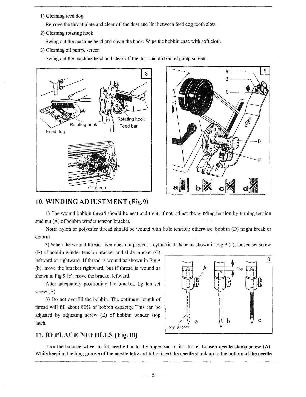
1)
Cleaning feed dog
Remove the throat plate and clear off the dust and lint between feed dog tooth slots.
2)
Cleaning rotating hook
Swing out the machine head and clean the hook. Wipe the bobbin case with soft cloth.
3)
Cleaning oil pump, screen
Swing out the machine head and clear off the dust and dirt on oil pump screen.
Feed dog
10.
WINDING
1)
The wound bobbin thread should
stud nut (A) ofbobbin winder tension bracket.
Note: nylon or polyester thread should
deform
2) When the wound thread layer does not present a cylindrical shape
of
bobbin winder tension bracket and slide bracket (C)
(B)
leftward or rightward.
(b), move the bracket rightward,
shown
in
Fig.9 (c), move the bracket leftward.
After adequately positioning the bracket, tighten set
screw (B).
3)
Do
not overfill the bobbin. The optimum length
thread will fill about 80%
adjusted by adjusting screw (E)
latch.
11.
REPLACE
Turn the balance wheel
While keeping the long groove
ADJUSTMENT
be
If
thread
is
wound
but
of
bobbin capacity. This can be
NEEDLES
to
lift needle bar
of
the needle leftward fully insert the needle shank up
as
if
thread
of
bobbin winder stop
(Fig.10)
(Fig.9)
neat and tight
be
wound with little tension; otherwise, bobbin (D) might break or
shown in Fig.9
is
wound
to
the upper end
if
as
of
not, adjust the winding tension by turning tension
as
shown in Fig.9 (a), loosen set screw
10
A
of
the needle
c
Long
a
groove
of
its stroke. Loosen needle clamp screw (A).
b
to
the bottom
-5-
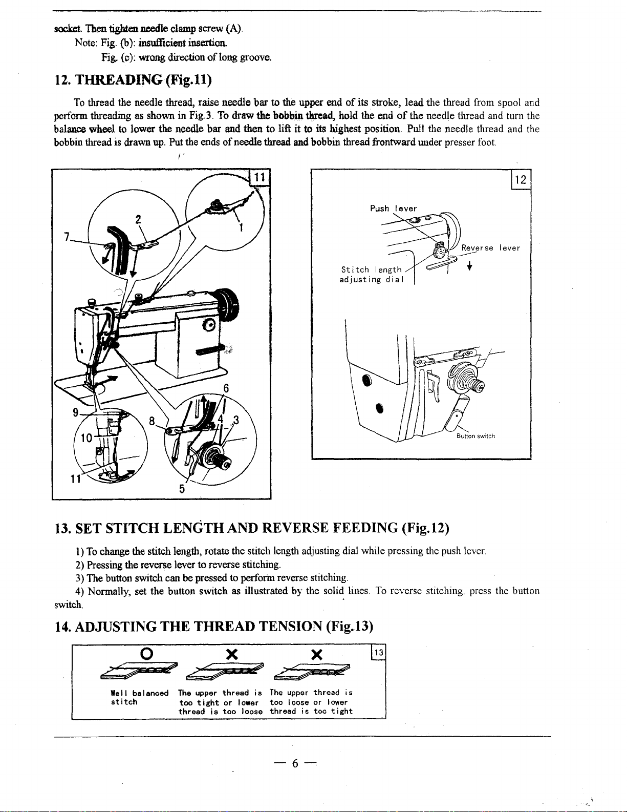
socket.
perform threading
balance wheel to lower
bobbin thread
Then tighten needle clamp screw (A).
Fig.
Note:
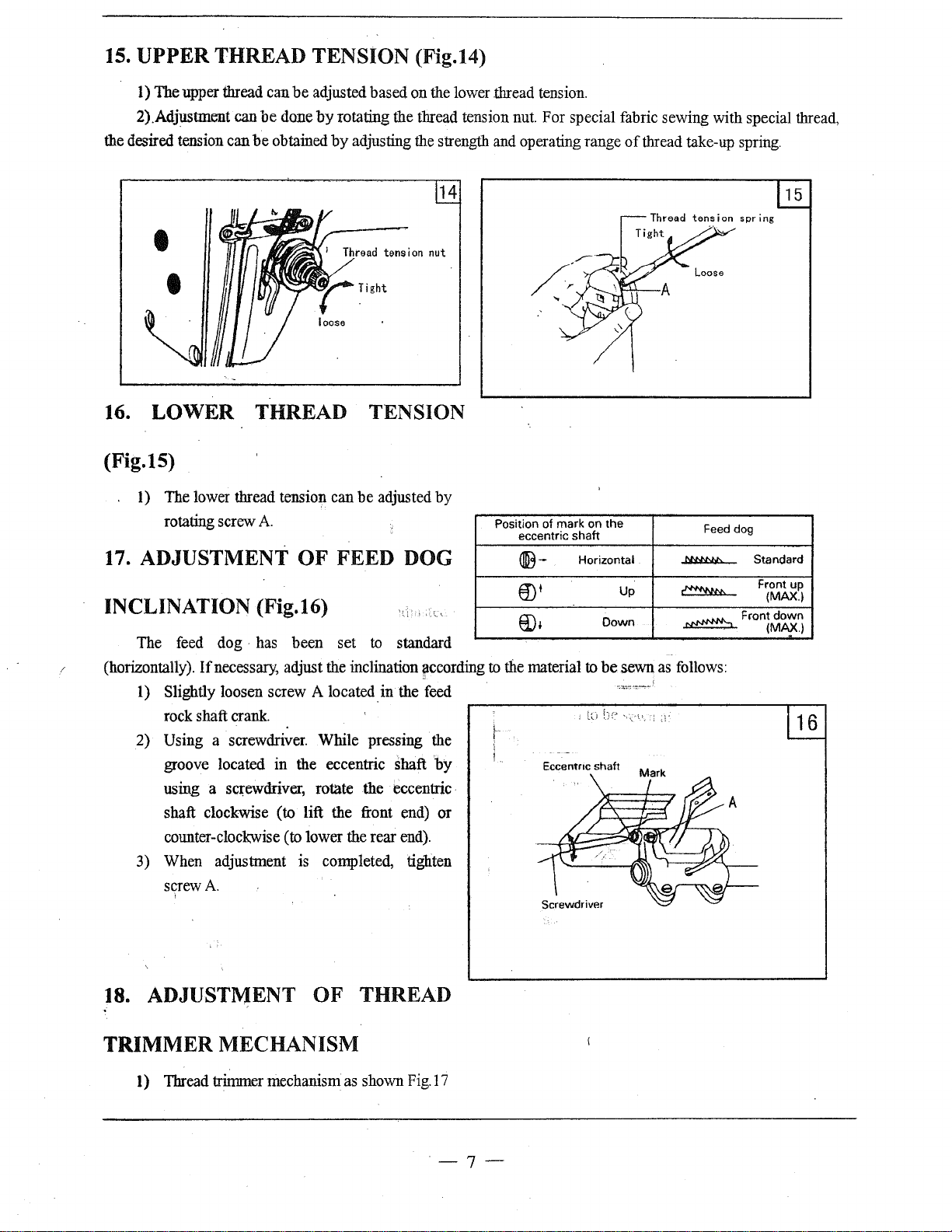
12.
THREADING (Fig.ll)
To
thread the needle thread, raise needle
(b): insufficient
Fig.
(c):
wrong
as
is
drawn
shown in Fig.3. To draw the
the
up.
insertion.
direction
needle bar and then to lift it to its highest position. Pull the needle thread and the
Put the ends
r·
oflong
of
groove.
bar
to the upper end
bobb.in
needle thread
of
its stroke, lead the thread from spool and
thread, hold the end
and
bobbin thread frontward under presser foot
of
the needle thread and turn the
12
Push
lever
Stitoh
adjusting
13.
SET STITCH LENGTH AND REVERSE FEEDING (Fig.12)
1)
To
change the stitch length, rotate the stitch length adjusting dial while pressing the push lever.
2)
Pressing the reverse lever to reverse stitching.
3) The button switch
4)
Normally, set the button switch
switch.
can be pressed to perforin reverse stitching.
as
illustrated by the solid lines.
·
le~~~''''
:~ahl
To
reverse stitching. press the button
i
''"''
~
14.
ADJUSTING
THE
THREAD TENSION (Fig.l3)
0 X X 13
.?%&
Well
st i toh
;#'
balanced
~
The upper
too
tight
thread
thread
or
is
too I oose
I ower
?*
-&::~
is
The
upper
too I oose
thread
is
thread
or
too
-6-
is
I ower
tight
-
··-
15.
UPPER
THREAD TENSION (Fig.14)
1) The upper thread can
2).Adjustment can
the desired tension can
16.
LOWER
be
adjusted based on the lower .thread tension.
be
done
by
rotating the thread tension nut. For special fabric sewing with special thread,
be
obtained
by
adjusting the strength and operating range
THREAD TENSION
(Fig.15)
.
I)
The lower thread tension can
rotating screw A
17. ADJUSTMENT
OF
be
FEED DOG
INCLINATION (Fig.16)
The feed
(horizontally).
1) Slightly loosen screw
rock shaft crank.
Using a screwdriver. While pressing the
2)
groove located in the eccentric
using a screwdriver, rotate the eccentric
shaft clockwise
coliD.ter-clockwise (to lower the rear end).
3) When adjustment is completed, tighten
screw A
dog·
has been set
If
necessary, adjust the inclination jiccording
to
A located in the feed
(to lift the front end) or
I
14
t~nsion
nut
adjusted by
standard
shaft
by
Position of mark on
eccentric shaft
®-
Horizontal
€D'
8)1
to
the material
Eccentnc
to
shaft
of
thread take-up spring.
the
MrNy,f.
as
follows:
~
~
Up
Down
be
sewn
Feed dog
Frontdown
Standard
Front up
(MAX.l
(MAX.)
18. ADJUSTMENT
TRIMMER
1)
Thread trinnner mechanism as shown
MECHANISM
OF
THREAD
Fig.
I 7
·-7-
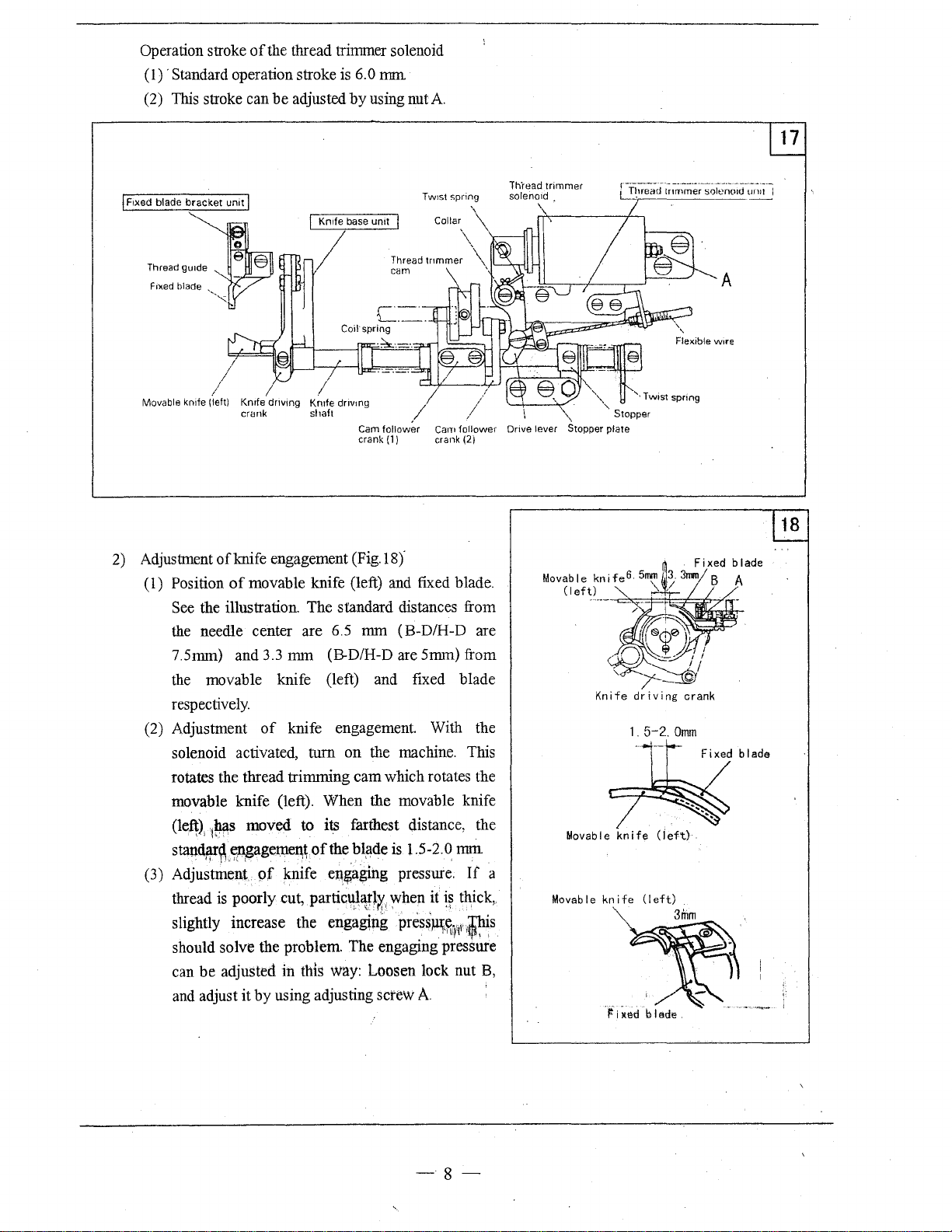
Operation stroke
(1)
·Standard operation stroke is 6.0
(2)
This
of
the thread trimmer solenoid
stroke can be adjusted
I Knrfe base
mm
by
using nut A
unit
r---
-----~--
-----------
------
Thread
trimmer
spring
Twrst
Collar
I
solenord
t_!~uead
tnrnrner
solenoid
--·-----~
-~.!_.1
Thread
glllde
Frxed blade
Movable knife (left)
2)
Adjustment
(
1)
'•,,,
/
/
Knrfe
crank
of
knife engagement (Fig.18)'
Position
See
the
of
the illustration. The standard distances from
needle center are 6.5 mm (B-D/H-D are
7.5mm) and
the
movable knife (left) and fixed blade
respectively.
(2) Adjustment
solenoid activated, turn on the machine. This
rotates the thread trimming cam which rotates the
movable knife (left). When the movable knife
(leff),
p.ts
1
standf!.r~,~gagerne~\
(3) Adjustment of knife
thread
is
poorly cut, partict¥¥lX,
slightly increase the engaging
should solve the problem. The engaging pressure
can be adjusted in this
and
adjust it by using adjusting screw A
I
driving
I
Krnfe
shaft
dr~vmg
cam
Cam
crank (1) crank (2)
,/
follower
Cam
follower
movable knife (left) and fixed blade.
3.3
mm (B-D/H-D are 5mm) from
of
knife engagement. With the
moved to
i~
farthest distance, the
of
the bliide is 1.5-2.0
e~~aging
pressure.
~hen
press~~~f
way:
Loosen lock nut
it
i~
mill
If
thick,
,ir,is
11
Drive lever Stopper
a
B,
'\
Movab
Movable
',,
I e
Stopper
"
plate
knife
knife
'·Twist
1.
5-2.
( i
spring
Omm
eft)
Flexible
Fixed blade
A
w~re
-8-

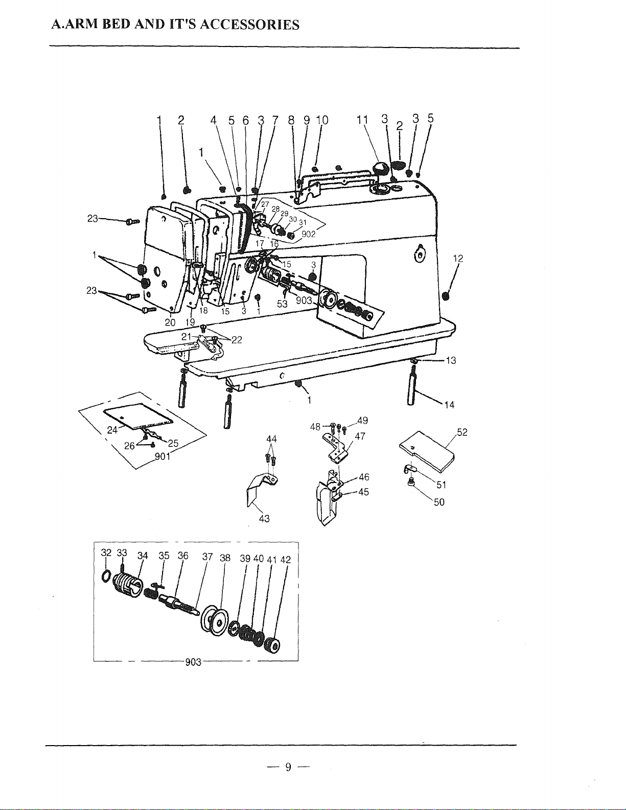
A.ARM BED AND
1 2
23~
IT'S
ACCESSORIES
12
/
44
4
~
43
<f;j52
~51
50
-9-
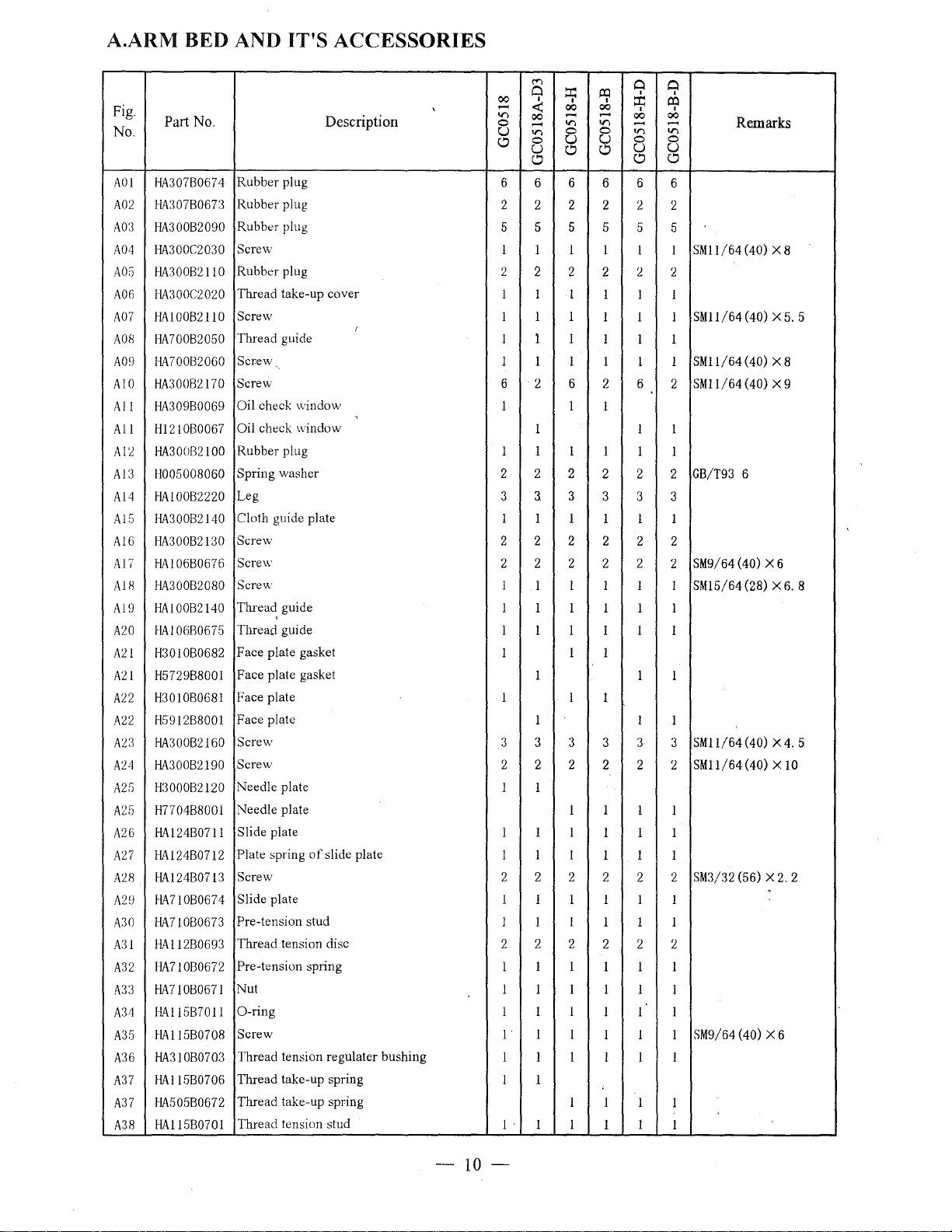
A.ARM BED AND
IT'S
ACCESSORIES
Fig.
No.
AOI
A02
A03
A04
A05
A06
A07
A
Oil
A09
AIO
All
All
A12
A13
A14
Al5
Al6
A17
A11l
Al9
A20
A21
A21
A22
A22
A23
A24
A25
A25
A26
A27
A28
A29
A30
A31
A32
A33
A34
A35
A36
A37
A37
A38
Part
No.
HA307B0674
HA307B0673
HA300B2090
HA300C2030
HA300B2110
HA300C2020
HAIOOB2110
HA70082050
HA700B2060
HA300B2170
HA30980069
Hl2IOB0067
HA300B2100
H005008060
HAIOOB2220
HA300B2140
HA300B2130
HAI06B0676
HA300B2080
HAIOOB2140
HA106B0675
H3010B0682
H5729B8001
H3010B0681
H5912B8001
HA300B2160
HA300B2190
H3000B2120
H770488001
HA124B07!1
HA124B0712
HA124B0713
HA710B0674
HA710B0673
HAI12B0693
HA710B0672
HA710B0671
HA115B7011
HAll5B0708
HA3!0B0703
HA115B0706
HA505B0672
HA115B0701
Description
Rubber plug
Rubber plug
Rubber plug
Screw
Rubber plug
Thread take-up cover
Screw
Thread guide
Screw
Screw
Oil check window
Oil check window
Rubber plug
Spring washer
Leg
Cloth guide plate
Screw
Screw
Screw
Thread, guide
Thread guide
Face plate gasket
Face plate gasket
Face plate
Face plate
Screw
Screw
Needle plate
Needle plate
Slide plate
Plate spring
Screw
Slide plate
Pre-tension stud
Thread tension disc
Pre-tension spring
Nut
0-ring
Screw
Thread tension regulater bushing
Thread take-up spring
Thread take-up spring
Thread tension stud
of
slide plate
I
.,
('<")
0
I
'
00
V)
-
0
u
Cl
6
2 2 2 2
~
00
<t:
00
V)
-
0
V)
-
0
u
u
Cl
Cl
6 6 6 6
5 5 5 5
1 1 1 l
2 2 2 2
"
"
I 1
1 1 l
I 1 1
1 1 I
1 I I I
6 2 6 2 6
1 1
0 0
I
l.l:l
I
00
.....
V)
0
~
l.l:l
::r:
I
00
00
.....
......
V)
V)
0
0
u u
Cl
Cl
I
I
6
2 2
5 5
I I SM11/64(40)
2
1
I 1 I
1 I 1
1 1
2
1
SMI1/64
SM11/64
SMII/64
Remarks
XB
(40) X 5.
(40)
X 8
(40)
X 9
5
1 1 l
1 I I
2 2
3
3.
I
I I I 1 I
2 2 2
2 2 2 2 2
I
I I I I I SM15/64(28) X6. 8
I 1 I
2 2 2 2
3
3 3 3
2 2 2
2
GB/T93
SM9/64
6
(40)
X 6
I I I 1 l l
1 I I I 1
1
1 1 1
1
1 1
1 1
3 3 3 3 3 3
2 2 2
1
2 2
1 1
I
SM11/64
SMII/64(40) X
2
(40) X 4.
10
5
1 1
I I
1 I 1
1 1 I
2 2 2 2
I I
1 I I
1 1 I
2 2
SM3/32
(56) X 2.
2
1 1 1 1 I 1
I 1 I I 1 1
2 2 2
1 1
l l 1 1 1
l 1
l 1 I
l I I
1
1
2
2 2
l l I
1 1 1
l I l
I I
I
1
SM9/64
(40)
X 6
1 I
I .
I 1
I 1 1
1
I
I
I
-10-
 Loading...