

Page 1
Purchasing
Copy
Dept
HIGH
LEAD
GC0398-1/GC0398-1-D
Heavy Duty Top And Bottom Feed
(With Automatic Thread Trimmer)
Lockstitch Sewing Machine
Instruction Manual
Parts
SHANGHAI HUIGONG N0.3 SEWING MACHINE FACTORY
Catalog
Page 2

Page 3
CONTENTS
1.
PRECAUTIONS BEFORES STARING OPERATION
1)
Safety precautions · · · · · · · · · · · · · · · · · · · · · · · · · · · · · · · · · · · · · · · · · · · · · · · · · · · · · · · · · · · · · · · · · · · · · · · · · · · · · · · · · · · · · · · · · · · · ·
2) Precautions before starting operation · · · .. · .. · · · · ·
3) Precautions for operation conditions
2.
Specifications
3.
Installing the
4.
Adjust:Inent
1)
Adjust:Inent
2)
Adjust:Inent
....................................................................................................
belt"·
.. ·
.. · ..
· .. · .. ·
of
needle
bar
stop position
of"UP"
of"DOWN"
position
position ...
........
........................
.......................................................................
· .. ·
........
...........................................................................
···
........................
3) Confirm the stop operation then the plug (12 pins) corning from the machine head into the
·
·"
.. · .. ·
.. · ..
receptacle ..
5.
Lubrication
6.
Condition
7.
Adjust:Inent
............................................................................................................
of
oil
lubrication"··········
of
the hook
· · .. · .. · · · · · · .. · · · · .. · · · · .. · ·
.........
···
...... · ........
lubrication·.............................................................................
....................................................
....
· .. · ·
....
· · · · ·
....
· · ..
"·
.. · .. · · · · .. · .. · · .. · · · ·
· .. · .. · .. · .. · .. · .. · .. ·
........
· .. · .. ·
..
· .. · .. · .. · .. · .. · .. · .. · 2
.........................................................
···
···
...
···
....
· .. · .. ·
..
· .. o •
....
······
..................
• • • •
.........
·" • ....
···
• • • •
···
··· ··· ···
..
• • • • • • •
.. ·
...
...
.. • .. • .. • ·..
· ..
····
....
· .. · 1
...
......
.. ··· .. · 3
..
.
..
2
2
2
2
3
3
8.
Adjust:Inent
9.
Periodical cleaning
10.
Installation
11.
How
12.
How
13.
How
14.
Adjust:Inent
15.
Adjusting the thread
16.
Upper thread
17.
Lower thread
18.
Adjust:Inent
19.
Feed dog height"' .. ·
20.
Adjust:Inent
21.
Presser bar
22.
Adjust:Inent
1)
Adjust:Inent
2)
To
foot
of
to
wind the lower thread .. · .. · · .. · .. ·
to
attach a needle
to
route the upper thread
change the balance
...............................................................................................................
oil pmnp .. · ·
...
ofbelt
cover · .. ·
of
stitch length and reverse sewing···· .. · ..
......
.. · ..
..........
· .. · .. · .. · ·
...............
....
· · .. · .. ·
· ·
....
· .. · · ..
·"
· ..
·"
.... · ......
· .. ·
....
· .. · .. · .. · .. · .. · .. · .. · ·
.... · ...... · ....
........................................................................
....
· · .. · .. ·
·" ·"
.. · ·
....
.. · ·
....
........ · .... · "·
· .. · · ..
·" · ....
....
· · .. · .. ·
· .. · · .. · ..
·""
·························
.. · .. · .. · ·
· ·
... · .. · .... · ·" ·" ·" ·"
.... · ·"
· ..
· .. ·
·"
.. ·
"·
"·
....
.. ·
"·
·" ·"
· .. ·
· .. · .. · .. · .. ·
· .. ·
.... · ..
..
· · .. ·
........ · ......
.. · .. · .. · · .. · ..
....
· .. · · .. · .. · .. ·
·············
tension....................................................................................
tension.............................................................................................
tension.............................................................................................
of
presser pressure·
........
of
feed
dog
inclination"'"'
lifter
.. ·
....
· .. ·
of
walking foot and presser foot
of
alternating n10vement· .. · · ·
....
· ..
····
.. · .. · ..
··
..
···
..
·······
..
··
.. · ..
·"
............
··············
· .. ·
..... · .......................
o •
..
· .. · ..
• •
.. • .. • ..
·"
o
.. • ....
........................................................................
..
··
........
· .. · ..
·"
.. · ·
....
· · .. · .. · .. ·
....
· .. · · .. · .. · .. ·
....
· · .. · .. · .. ·
..................................................................
"·
· · · · · · .. · · · · · · · · · · .. · · .. · .. · .. · .. · .. · · · ·
of
the alternating movements between the walking foot and presser
....
· .. · .. · .. · · · · · .. ·
·......
·"
.. ·
....
· .. · · .. · .. ·.. 4
....
..
··
....
• • • • • •
..
• •
....
• •
.....
·.. ...
........
· ..
3
" 4
·"
4
· .. · 5
· 5
6
6
• 6
7
·..
7
7
....
· 7
8
3
6
7
3) Installing the
4) Feed pitch adjust:Inent
Adjust:Inent
23.
24.
Adjust:Inent
feed
regulator bracke ...
of
walking foot
of
feed
timing······
of
thread trimmer mechanism·
.................................................................................
...
...
... ...
...
......
... ...
... ... ...
... ... ... ...
.....................................................................
....
· .. · ..
··
.. · .. ·
........
· .. ·
.... · ...... · ........
...
... ... ...
· .. ·
... ... ... 8
....
··
.. · .. ·
"1
8
9
0
Page 4

1)
The
thread
t:rinnner
2)
Installing the thread trimmer solenoid unit · · · · · · · · · • · · · · · · · · · · · · · · · · · · · · · · · · · · · · · · · · · · · · · · · · · · · · · · · · · · · · ·
3)
Adjustment ofknife engagement
25.
Needle, Thread and Material
:mechanism
to
illustrated as· ..
·············································
be Sewn · · · · .. •
·····················
....
· .. ·
......
· .. · .. · .. · .. · .. •
· · · · · · · · · · · · · · · · · · · · · · · · · · · · · · · · · · · · 1 0
······························
........
· .. · .. · .. · .. · .... · ·..
10
10
11
Page 5
1.
PRECAUTIONS
1)
Safety precautions:
BEFORES
STARING
OPERATION
(1) When turning the power on, keep your hands and fingers away from the
and
the
area around the pulley.
Power nmst
(2)
(3)
Power must
the machine, or when replacing.
(4) Avoid placing fingers, hairs, bars etc., near the pulley,
the machine is in operation.
(5) Do not insert fingers into the thread take-up cover, under/around the needle, or pulley when the machine
is
in operation.
If
a belt cover, finger guard, eye guard are installed, do not operate the machine without these safety
(6)
devices.
2)
Precautions before starting operation:
(1)
If
the machine's oil
(2)
If
the machine is lubricated
(3) When a new sewing machine is first turned on, verify the rotational direction
on.
power
(The pulley should rotate counterclockwise when viewed from the pulley)
Verity the voltage and (single or three) phase with those given on the machine nameplate.
(4)
be
be
turned
turned
pan
off
when the machine is not in use, or when the operator leaves the seat.
off
when tilting the machine head, installing or removing the
"V"
belt, bobbin winder pulley, or motor when
has an oil sump, never operate the machine before filling
by
a drop oiler, never operate the machine before lubricating.
area
around/under the needle
"V"
belt, adjusting
it.
of
the pulley with the
3) Precautions for operating conditions:
1)
Avoid using the machine at abnormally high temperatures
lower) .
2)
Avoid using the machine in dusty conditions.
2.
Specifications:
ns
Material Weight
Bar
Speed
Stroke
Max. Sewing
Stitch Length
Needle
Thread Take-up Lever Stroke
Alternating Movement
Walking Foot Alternate Operating System
Feed Dog Height
Needle
Presser Foot Stroke
Lubrication System
Thread Trinnner
Touch Back
By Hand
By Knee
(35'C
GC0398-1
X
or higher) or low temperatures ( 5'C or
GC0398-1-D
Heavy
2,000rpm
Q-10nnn
35.0nnn
72.0nnn
2.0-5.0
DPX17
nnn
Dial
1.0
nnn
14#-24#
6.0nnn
16.0
nnn
Automatic
I
0
0
-1-
Page 6
3.
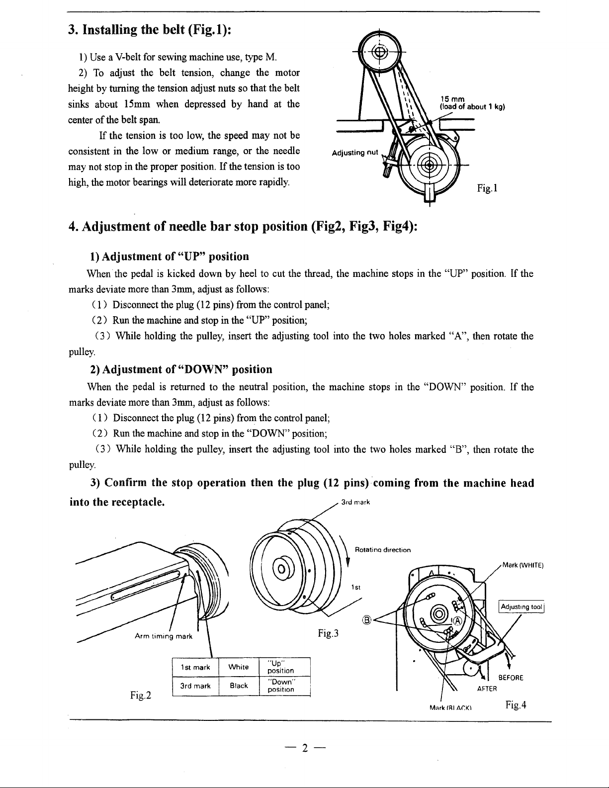
Installing the belt (Fig. I):
1)
Use a V-belt for sewing machine use, type M.
2)
To
adjust the
by
height
sinks
center
consistent
may not stop in the proper position.
high, the motor bearings will deteriorate more rapidly.
4.
marks deviate more than
pulley.
turning the tension adjust nuts so that the belt
about 15mm when depressed
of
the belt span.
If
the tension is too low,
in
the low or medium range,
Adjustment of needle
1)
Adjustment of
When· the pedal is kicked down
(
1)
Disconnect the plug (12 pins) from the control panel;
( 2 )
Run
(3)
While holding the pulley, insert the adjusting tool into the
belt
tension, change the motor
by
the
speed
If
the tension is too
bar
stop position (Fig2, Fig3, Fig4):
"UP"
3mm,
the machine and stop in the
position
by
adjust as follows:
hand at the
may
not
or
the
needle
heel to cut the thread, the machine stops in the "UP" position.
"UP"
position;
be
two
holes marked "A", then rotate the
If
the
2)
Adjustment of "DOWN" position
When the pedal is returned to the neutral position, the machine stops in the
3mm,
marks deviate more than
adjust as follows:
( 1) Disconnect the plug (12 pins) from the control panel;
(
2)
Run
the machine and stop in the
(3)
While holding the pulley, insert the adjusting tool into the two holes marked
pulley.
3) Confirm the stop operation then the plug
"DOWN"
position;
(12
pins) coming from the machine head
into the receptacle.
I~
Fig.3
"DOWN"
"B",
position.
then rotate the
If
Mark
the
(WHITE)
"Up"
position
"Down"
posit1on
Fig.2
1st mark
3rd mark
White
Black
-2-
M~rk
IRI
Ar.KI
BEFORE
Fig.4
Page 7
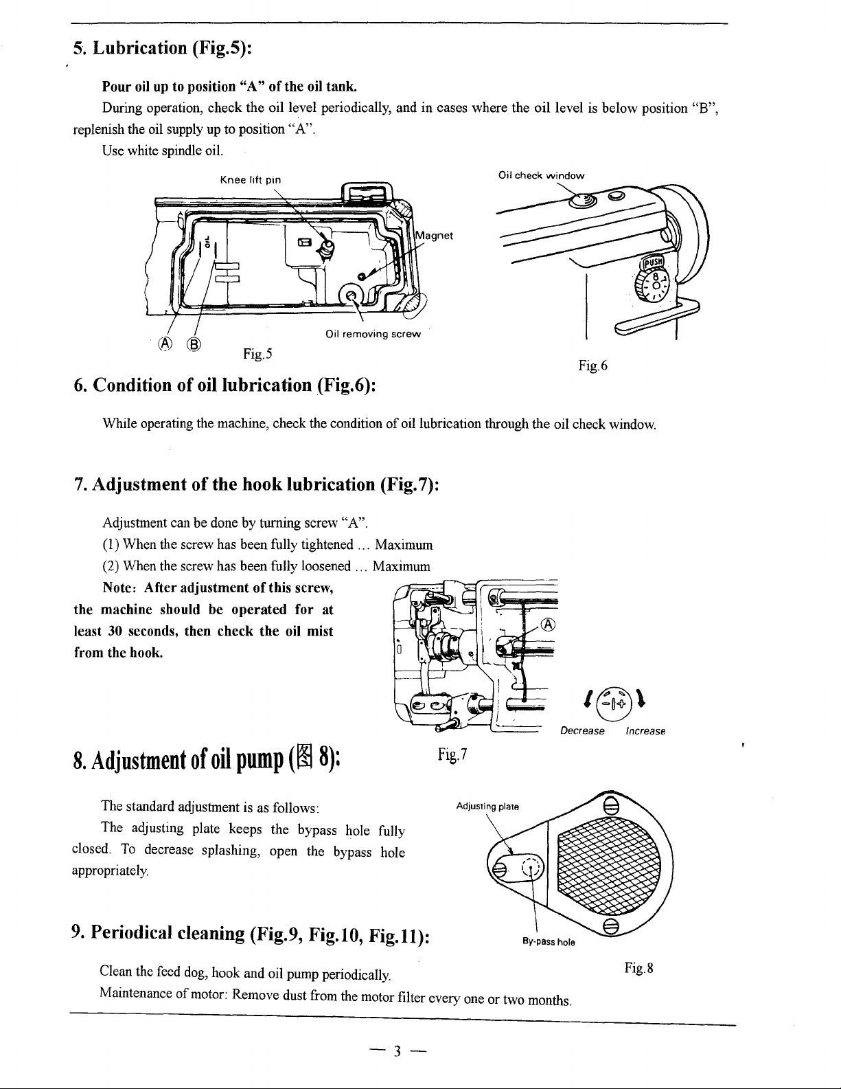
5.
Lubrication (Fig.5):
Pour
oil
up
to position
During operation, check the oil level periodically, and
replenish the oil supply up to position "A".
Use white spindle oil.
"A"
of the oil tank.
in
cases where the oil level is below position
"B",
Knee
lift
pin
®@
6.
Condition of oil lubrication (Fig.6):
While operating the machine, check the condition
7.
Adjustment of the hook lubrication (Fig. 7):
Adjustment can be done
(1) When the screw has been fully tightened ... Maximum
(2) \Vhen the screw has been fully loosened ... Maximum
Note: After adjustment
the machine should be operated for at
30
least
from the hook.
seconds, then check the oil mist
Fig.5
by
turning screw "A".
of
this screw,
Oil removing
screw
of
Oil check
oil lubrication through the oil check window.
window
Fig.6
8.
Adjustment
The standard adjustment is as follows:
The adjusting plate keeps the bypass hole fully
closed.
appropriately.
9.
To
decrease splashing, open the bypass hole
Periodical cleaning (Fig.9, Fig.lO,
Clean the feed dog, hook and oil pump periodically.
Maintenance
of
oil
pump(~
of
motor: Remove dust from the motor filter every one or two months.
8):
Fig.ll):
Fig.7
Adjusting plata
-3-
By-pass
Decrease
hole
Increase
Fig.8
Page 8
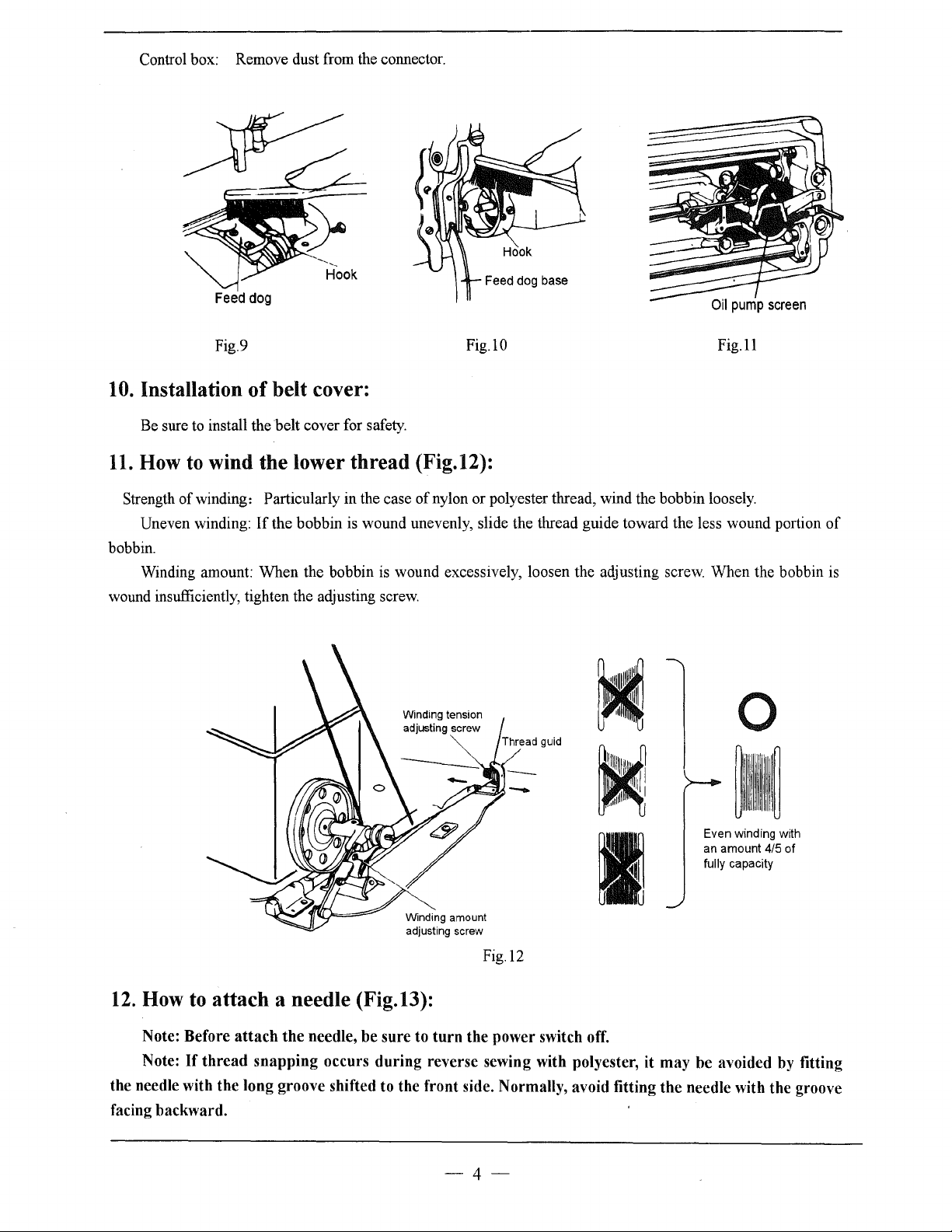
Control box: Remove dust from the connector.
Feed
dog
Fig.9
10.
Installation
Be sure to install the belt cover for safety.
11.
How
Strength
Uneven winding:
bobbin.
wound insufficiently, tighten the adjusting screw.
to
of
winding: Particularly in the case
Winding amount: When the bobbin is wound excessively, loosen the adjusting screw. When the bobbin is
of
belt cover:
wind the lower
If
the bobbin is wound unevenly, slide the thread guide toward the less wound portion
thread
Winding tension
adjusting screw
(Fig.12):
of
Fig.lO
nylon or polyester thread, wind the bobbin loosely.
Fig.ll
0
of
Winding amount
adjusting screw
Fig.l2
12.
How
Note: Before
Note:
the needle with the long groove shifted to the front side. Normally, avoid fitting the needle with the groove
facing backward.
to
attach a needle (Fig.13):
If
thread
attach
the needle, be sure to
snapping occurs during reverse sewing with polyester, it may be avoided by fitting
turn
the power switch off.
-4-
Even
winding with
an
amount
fully capacity
4/5
of
Page 9
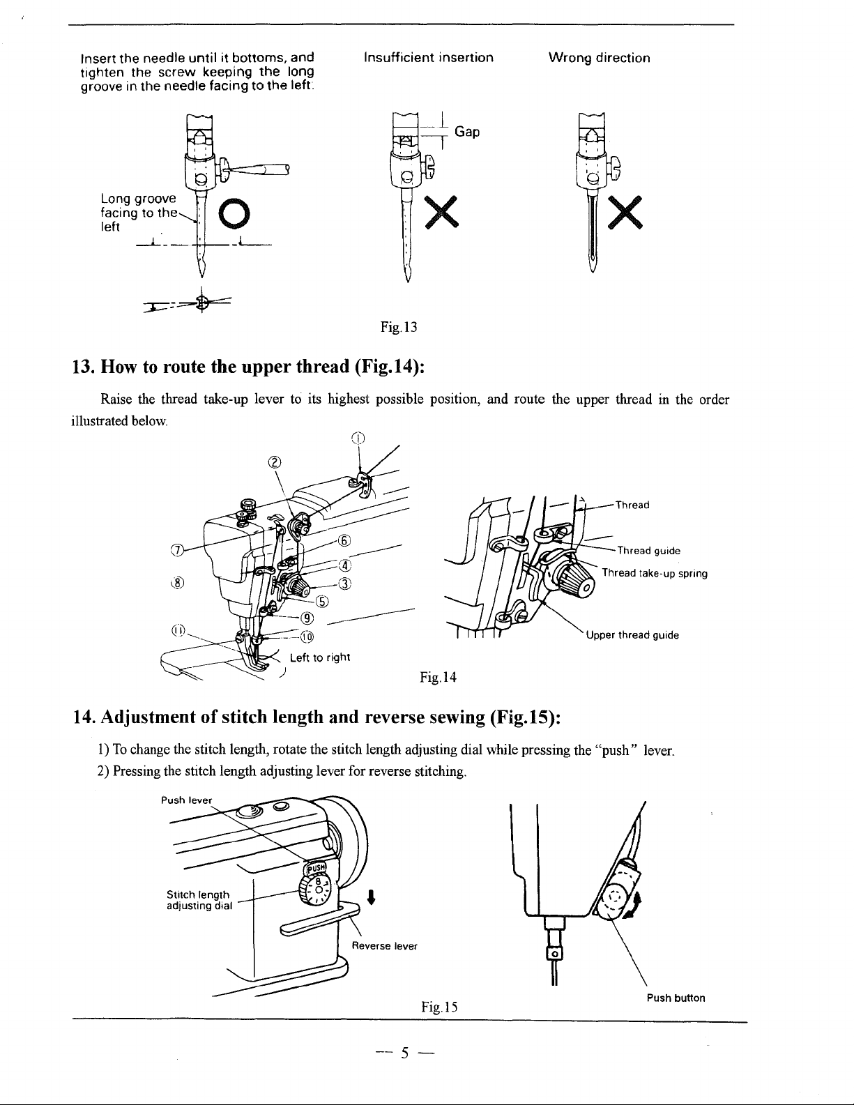
Insert
the
tighten
groove in
Long groove
facing to
left
13.
How
Raise the thread take-up lever to its highest possible position, and route the upper thread in the order
illustrated below.
needle
the
the
to
until
it
screw
needle
the
bottoms,
keeping
facing
the
to
and
long
the
left~
0
route the upper thread (Fig.14):
Insufficient
Fig.l3
(i)
insertion
Wrong
direction
X
Left
to
right
)
14.
Adjustment
1)
To
change the stitch length, rotate the stitch length adjusting dial while pressing the "push" lever.
2)
Pressing the stitch length adjusting lever for reverse stitching.
of
stitch length and reverse sewing (Fig.15):
Thread
Thread take-up spring
Upper thread guide
Fig.l4
Fig.l5
--5-
Push button
Page 10
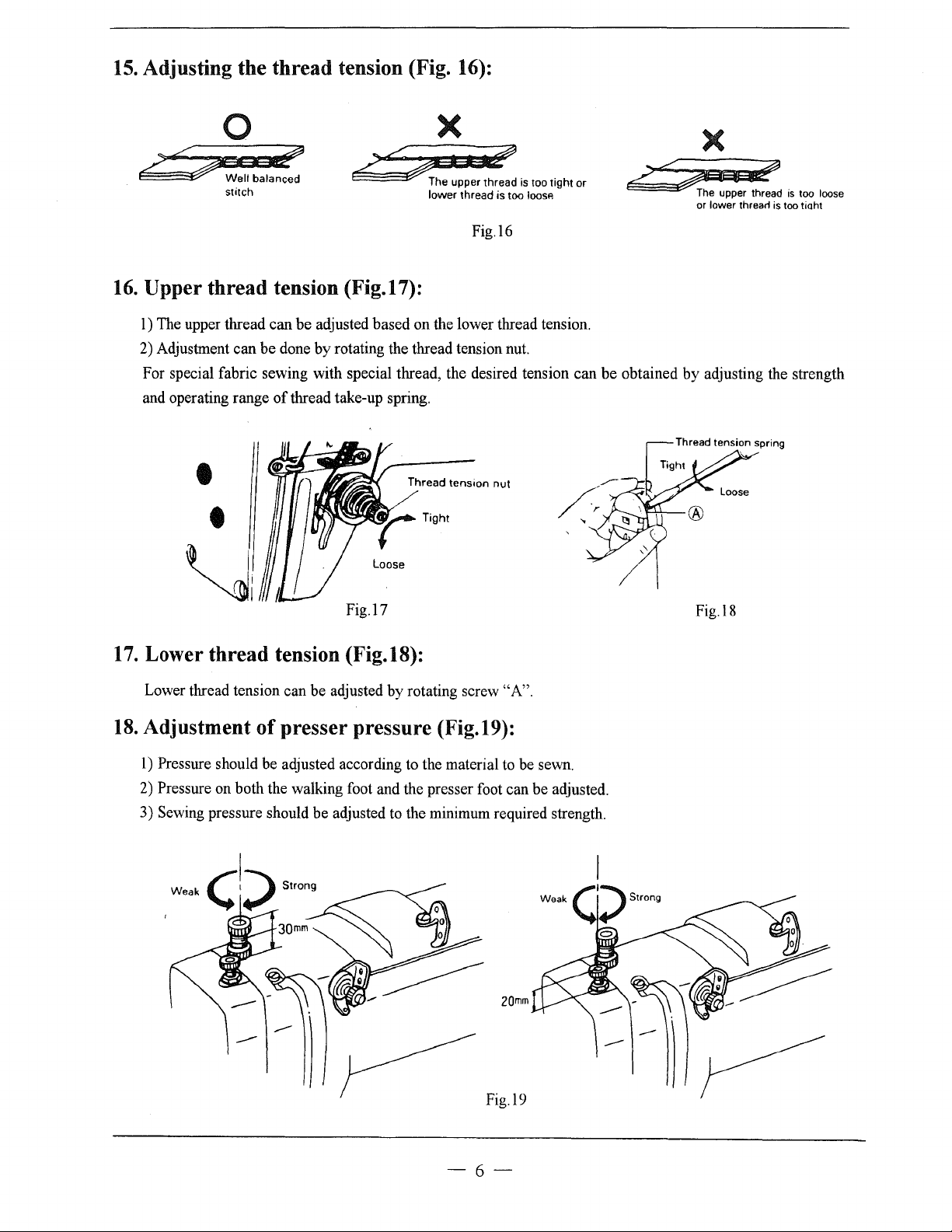
15.
Adjusting the
thread
tension (Fig. 16):
0
:;
/?o:?Jit;;
~
16.
Upper
1) The upper thread can
2) Adjustment can be done
For special fabric sewing with special thread, the desired tension can
and operating range
Well
stitch
thread
-d3
balanced
tension (Fig.17):
be
adjusted based on the lower thread tension.
by
rotating the thread tension nut.
of
thread take-up spring .
~~
~·~.'
X
The upper thread
lovverthreadistoo
Thread
tension
ts
loosP.
Fig.l6
nut
•
•
Loose
too ttght
or
?2~
be
obtained
by
X
The
upper thread
or
lovver
threarl
adjusting the strength
is
is
too tiaht
too
loose
~~
Fig.l7
17.
Lower
Lower thread tension can be adjusted
18.
Adjustment
1)
Pressure should be adjusted according to the material to be sewn.
2)
Pressure on both the walking foot and the presser foot can be adjusted.
3) Sewing pressure should be adjusted to the minimum required strength.
thread
of
tension (Fig.18):
by
rotating screw "A".
presser pressure (Fig.19):
2Qmm
Fig.l8
Fig.l9
-6-
Page 11
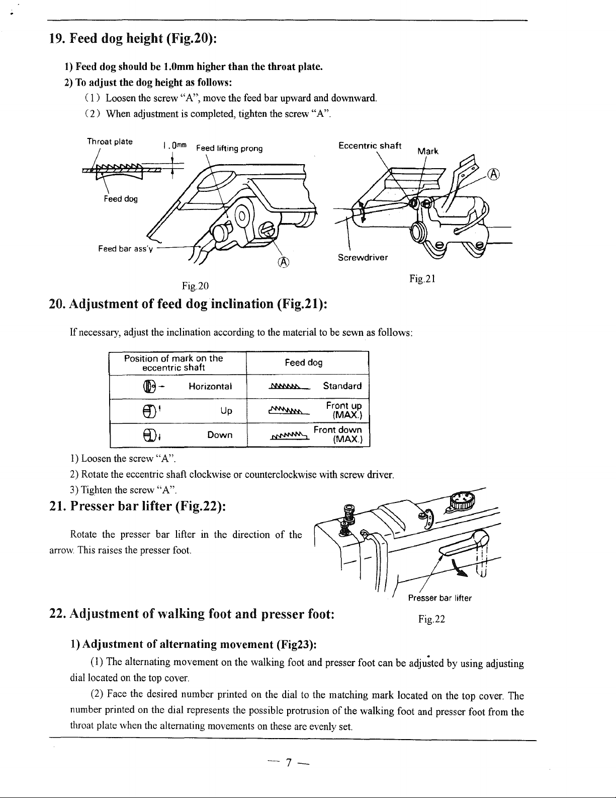
19.
Feed dog height (Fig.20):
1)
Feed dog should
2)
To
adjust
the
( 1 ) Loosen the screw
2)
When adjustment is completed, tighten the screw
(
be
l.Omm
dog height as follows:
higher
"A",
than
the
throat
move the feed bar upward and downward.
plate.
"A"
.
Feed
.
:~a.+
Feed
dog
Feed
bar ass'y
Fig.20
20.
Adjustment
If necessary, adjust the inclination according
of
feed dog inclination (Fig.21):
Position
of
eccentric shaft
~-
mark
Horizontal
on
ID'
8),
lifting prong
the
Up
Down
®
to
the material
Feed dog
MN\N.lo..
~
~
to
be sewn
Standard
Front up
(MAX.)
Front
(MAX.)
Eccentric
as
down
shaft
Fig.21
follows:
1)
Loosen the screw "A".
2)
Rotate the eccentric shaft clockwise or counterclockwise with screw driver.
3) Tighten the screw
21.
Presser
Rotate the presser bar lifter in the direction
arrow.
This raises the presser foot.
22.
Adjustment
1)
Adjustment
dial located on the top cover.
number printed on the dial represents the possible protrusion
throat plate when the alternating movements on these are evenly set.
bar
(1) The alternating movement on the walking foot and presser foot can be
(2) Face the desired number printed on the dial to the matching mark located on the top cover. The
"A".
lifter (Fig.22):
of
the
of
walking foot and presser foot:
of
alternating
movement (Fig23):
Fig.22
adju;ted
of
the walking foot and presser foot from the
by
using adjusting
-7-
Page 12
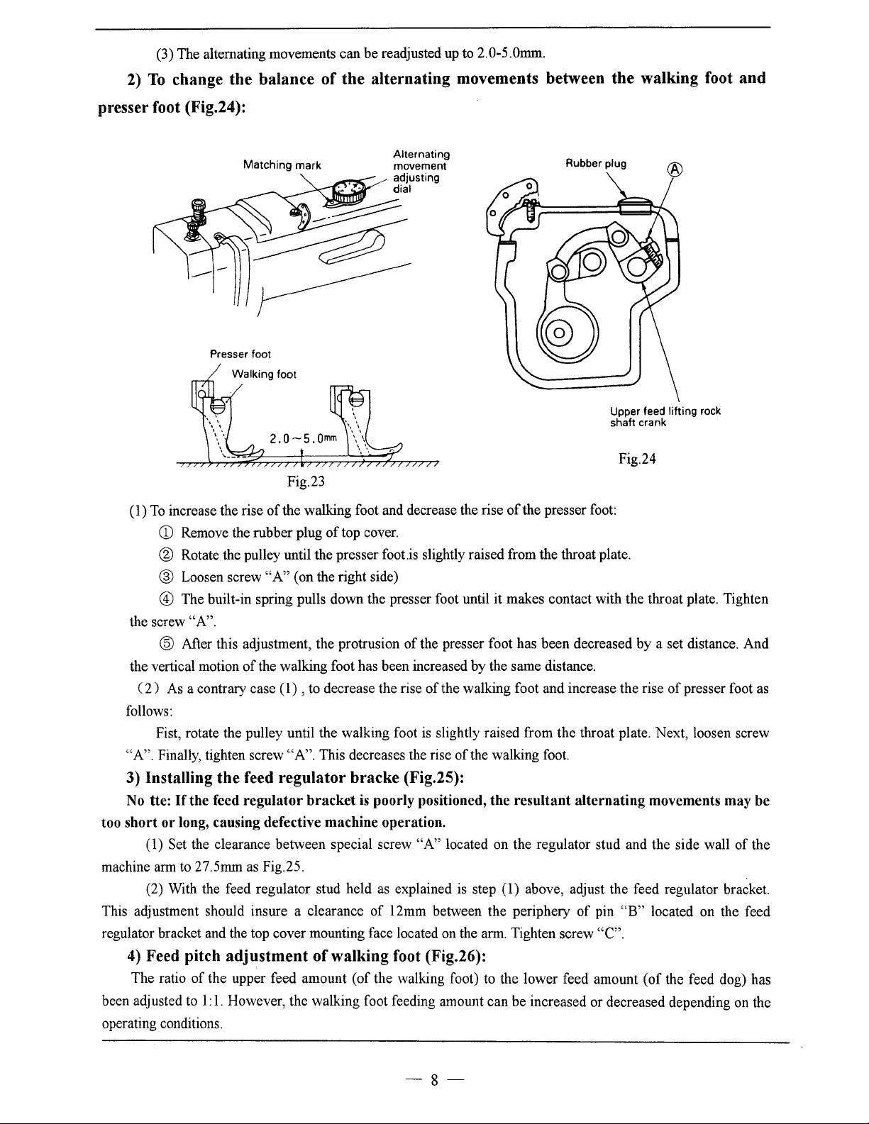
(3) The alternating movements can be readjusted
2)
To
change the balance
presser foot (Fig.24):
up
to 2.0-5.0mm.
of
the alternating movements between the walking foot and
Alternating
movement
adjusting
dial
of
the presser
.is
slightly raised from the throat plate.
of
the presser foot has been decreased by a set distance. And
by
the same distance.
of
the walking foot and increase the rise
is
slightly raised from the throat plate. Next, loosen screw
of
the walking foot.
(1)
To
increase the rise
CD
Matching
Presser foot
Remove the rubber plug
mark
Fig.23
of
the walking foot and decrease the rise
of
top cover.
® Rotate the pulley until the presser foot
@ Loosen screw
@ The built-in spring pulls down the presser foot until it makes contact with the throat plate. Tighten
the screw
the vertical motion
2)
(
follows:
"A". Finally, tighten screw
"A".
@ After this adjustment, the protrusion
As
a contrary case ( 1) , to decrease the rise
Fist, rotate the pulley until the walking foot
"A"
(on the right side)
of
the walking foot has been increased
"A".
This decreases the rise
Rubber plug
3) Installing the feed regulator bracke (Fig.25):
No tte:
too short or long, causing defective machine operation.
machine arm to 27.5mm
This adjustment should insure a clearance
regulator bracket and the top cover mounting face located on the arm. Tighten screw
4) Feed pitch adjustment
The ratio
been adjusted to
operating conditions.
Ifthe
feed regulator bracket
(1) Set the clearance between special screw
as
Fig.25.
(2) With the feed regulator stud held
of
of
the upper feed amount (of the walking foot)
I:
1.
However, the walking foot feeding amount can be increased or decreased depending on the
is
poorly positioned, the resultant alternating movements may be
as
explained is step (1) above, adjust the feed regulator bracket.
of
12mm between the periphery
walking foot (Fig.26):
"A"
located on the regulator stud and the side wall
of
to
the lower feed amount (of the feed dog) has
Upper feed lifting rock
shaft crank
Fig.24
foot:
of
pin
"B"
located on the feed
"C".
presser foot
of
as
the
-8-
Page 13
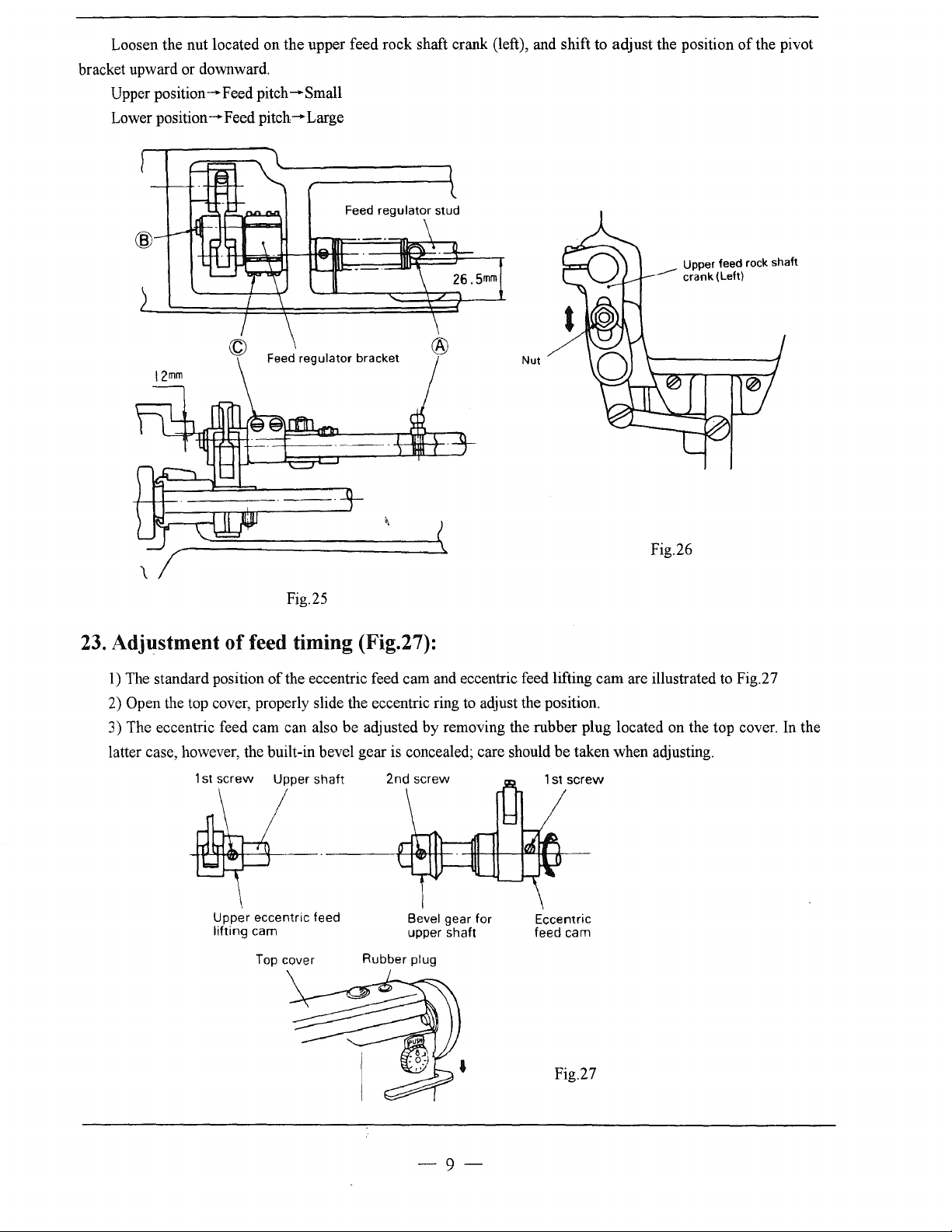
Loosen the nut located on the upper feed rock shaft crank (left), and shift to adjust the position
bracket upward or downward.
Upper
position-Feed
Lower
position-Feed
pitch-Small
pitch-Large
Feed
regulator bracket
__....-
Nut
of
the pivot
Upper feed rock shaft
crank (Left)
Fig.26
Fig.25
23.
Adjustment
1)
The standard position
Open the top cover, properly slide the eccentric ring
2)
of
feed timing (Fig.27):
of
the eccentric feed cam and eccentric feed lifting cam are illustrated
to
adjust the position.
to
Fig.27
3) The eccentric feed cam can also be adjusted by removing the rubber plug located on the top cover. In the
latter case, however, the built-in bevel gear is concealed; care should be taken when adjusting.
1st
screw
Upper
lifting
Upper
shaft
eccentric feed
cam
Top cover
Bevel gear for
upper shaft
Rubber plug
1st
screw
Eccentric
feed cam
Fig.27
-9-
Page 14
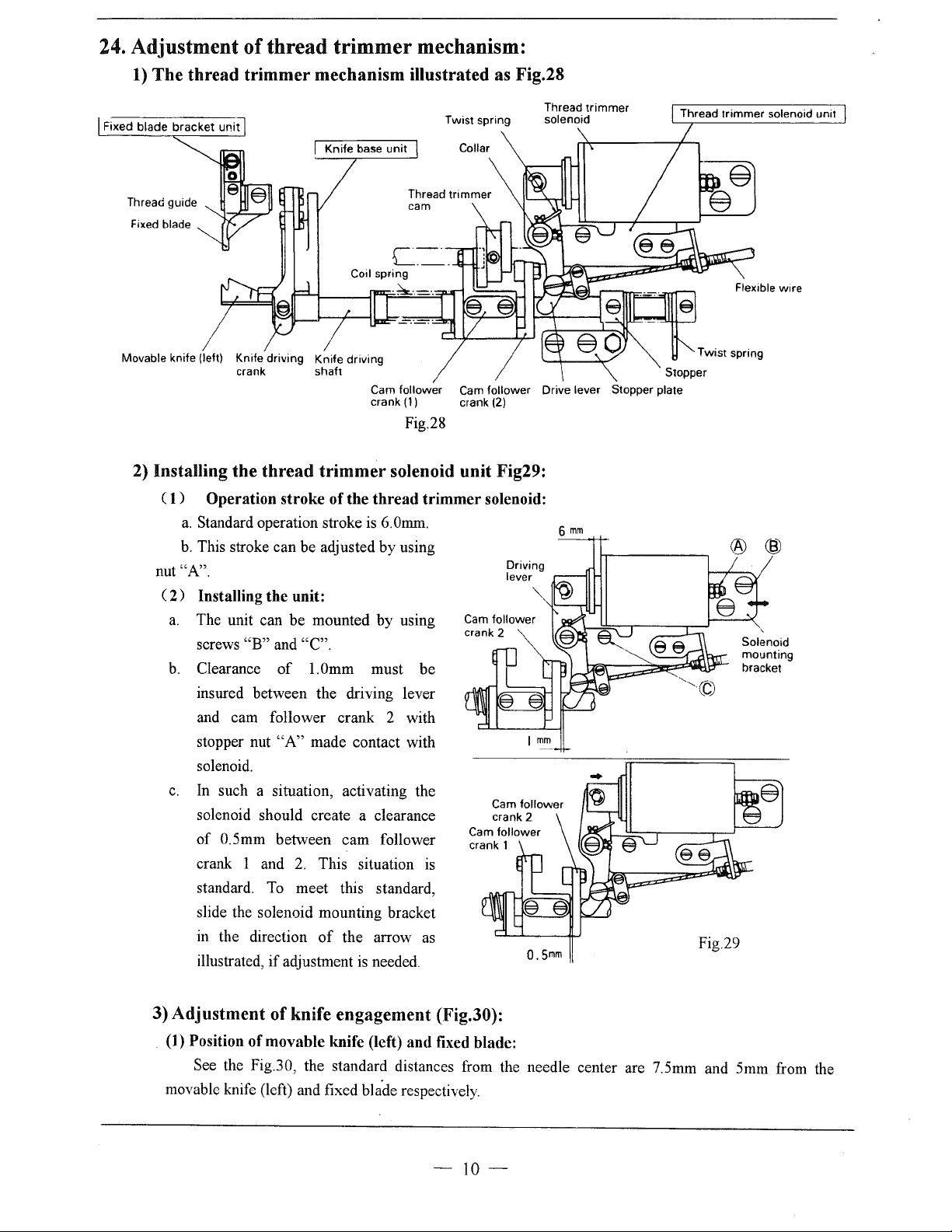
24. Adjustment
1)
The thread trimmer mechanism illustrated
Fixed blade
of
thread trimmer mechanism:
Twist spring
as
Fig.28
Movable knife (left) Knife driving Knife driving
crank shaft
Cam follower
(1)
crank
Cam
follower Drive lever Stopper plate
crank
(2)
Fig.28
2) Installing the thread trimmer solenoid unit Fig29:
(
1)
Operation stroke
a.
Standard operation stroke
b.
This stroke can be adjusted by using
"A".
nut
(
2)
Installing the unit:
a.
The unit can be mounted by using
"B"
screws
b.
Clearance
and "C".
of
insured between the driving lever
and cam follower crank 2 with
stopper nut
"A"
solenoid.
c.
In
such a situation, activating the
solenoid should create a clearance
of
0.5mm between cam follower
crank 1 and
standard.
To
slide the solenoid mounting bracket
in the direction
illustrated,
if
of
the thread trimmer solenoid:
is
6.0mm.
l.Omm must
made contact with
2.
This situation
meet this standard,
of
the arrow
adjustment
is
needed.
be
is
as
6
O.Smm
mm
® ®
Solenoid
mounting
bracket
Fig.29
3) Adjustment
(1) Position
of
knife engagement (Fig.30):
of
movable knife (left) and fixed blade:
See the Fig.30, the standard distances from the needle center are 7.5mm and 5mm from the
movable knife (left) and fixed
bla'de respectively.
-
10-
Page 15

(2) Adjustment
With the solenoid activated,
machine. This rotates the thread trimming cam
which rotates the movable knife (left). When the
movable knife (left) has moved to its farthest
distance, the standard engagement
1.5mm-2.0mm. The engagement can be adjusted by
properly mounting the drive arm.
(3) Adjustment
a.
If
a thread is poorly cut, particularly when it is
thick, slightly increase the engaging pressure. This
should solve the problem.
b.
The engaging
way:
Loosen lock nut
adjusting screw
of
of
pre~ure
"A".
knife engagement:
turn on the
of
the blade
knife engagement pressure:
can
be
adjusted in this
"B"
and adjust it
by
using
is
Fixed blade
Knife driving crank
1.5-2.Qmm
Fixed blade
Movable knife (left)
25.
Needle, Thread and Material
Needle Size
No.
14
No.
16
No.
22
Thread No.
No.
60-
No.
No.
30-
No. 50
65
to
be Sewn
Movable
Material
Cotton, Woolen
Muslin, Woolen, Tarpaulin,
Medium Leather, Canvas
knife (left)
Fixed blade
Fig.30
Thin
Leather
-
11-
Page 16

A.ARM _
B
EDAN.~D~I_T
ACCESSORIES
__
s ________
__
-12-
Page 17

A.ARM BED AND ITS ACCESSORIES
Fig.
.
Part
No.
A01
A02
A03
A04
AOS
A06
A07 HA700F2100
A08
A09
A10 H6023B8001 Stopper pin for upper feed lifting
All
A12
A13
A14
A15
A16
A17
A18
A19
A20
A21
A22
A23 H005008060 Spring washer
A24
A25
A26
A27
A28
A29
A30
A31
A32
A33
A34
A35
A36 HA500C2070
A37
A38 HA115B7011
A39
A40
A41
A42
A43
No.
HA300B2090 Rubber plug
HA300B2110
HA300B2160 Screw
H6512B8001
H6513B8001 Gasket for
HA307B0673
H6017B8001
H6022B8001
H431040060 Set screw
H6024B7101
HA300C2030 Screw
H6515B8001 Top cover
H6516B8001 Gasket for top cover
H1210B0067
H6030B8001 Rubber plug
H6032B8001 Rubber plug
H6518B8001
HA600C2020
HA100B2110
HA300B2100 Rubber plug
HA100B2220 Leg
HA710B0671 Pre tension adjusting nut
HA710B0672 Thread tension spring
HA112B0693 Thread tension disc
HA710B0673 Thread tension stud
HA710B0674 Thread guide
HA106B0676 Screw
HA600B2050 Thread guide
HA300B2080 Screw
HA300B2130
HA300B2140 Cloth guide plate
HA307B0674 Rubber plug
HA500C2060 Thread guide
HA310B0703
HA505B0672
HA115B0709 Thread releasing pin
HA115B0701
HA310B0705 Thread tension disc
Rubber plug
Arm
side
cover
arm
Rubber plug
Screw
Thread guide
Coil spring for upper feed lifting
Dial for upper feed lifting
Oil
check window
Upper feed lifting regulator cam
Thread take-up cover
Screw
Screw
Screw
0-ring
Thread tension regulator bushing
Thread take-up spring
Thread tension stud
Description
side cover
I
1
I
1
I
D
4 .
4
1 1 (cp5.7)
6 6
1 1
1 1
3 5
1 1 SM11/64(40)x7
1
1 1
1 1
2 2
1 1
7
1 1
1 1
1 1
1 1
1 1 (
1 1
1
1 1
1
2
3 3
2
1 1
1 1
2 2
1 1
2 4
1
1 1
1
1 1
1 1
1 1
1 1
2 2
(cp8.8)
SM11/64(
(cpl9)
1
GB!T80
7 SM11/64(40)x8
(cp22)
cp26)
1
SM11/64(40)x5.5
(cp27)
1
2 GB!T93 6
1
1
2
1
1
2 SM9/64(40)x6
SM15/64(28)
SM11/64(40)x5.5
(cp11.8)
1 SM9/64(40)x5
1
Remarks
40)x9
M4x6
'
-13-
Page 18

A.ARM BED AND ITS ACCESSORIES
Fig.
No.
A44 HA310B0702 Thread tension releasing disc
A45 HA505B0671
A46 HA115B7010
A47
A48
A49 HA607B0671
A50
A51
A52
A53
A54 HA300B2190
A55
A56
A57 H6517B8001
A58 HB5253B081
A58 H6507B8001
A59 HB5254B081 Bed
A59 H6508B8001
A60
Part
No.
Thread tension spring
Thumb nut revolution stopper
HA310B0701
HA115B0708 Screw
HA124B0713
HA124B0712
HA124B0711 Slide piate
H1100B2060
HA700B2030 Screw
H5341B8001 Screw
HA100B2100
Thumb nut
Thread guide
Screw
Plate spring for slide plate
Needle plate
Screw
Fave plate
Arm
Arm
Bed
Three hole thread guide
Description
I
1
I
1
I
D
1 1
1
1
1
1
1
1
1
1
2
1
1
1
2 2
2
1 1 SM11/64(40)x26
1
1
1
1
SM9/64{40)x6
1
1
2
1
1
1
2
1
1
1
Remarks
-14-
Page 19

B.SEWING MECHANISM
(
~EJ--38
me··
!
"44
L
__
37
-15-
Page 20

B.SEWING MECHANISM
Fig.
No.
BOI
B02
B03 HAIOOC2080
B04
B05 HA804B0652
B06 HA500C2060
B07 HA500C2030
B08 H2000G2030
B09
BlO
Bll
B12
B13
B14
B15
Bl6
Bl7
Bl8
Bl9
B20 H6013C8001
B21
B22
B23
B24
B25
B26 HA112D3013
B27
B28
B29 HA7311C206 Feed
B30 HA7311C306 Set screw
B31
B32
B33
B34 HA113D2112 Upper shaft gear
B35
B36 HA100D2110
B37
B38
B39 HA113D2222 Vertical shaft gear (upper)
B40 HA113D2212 Lower shaft gear
B41
B42 H6506D8001
B43
Part
No.
HA300B2090
HAIOOC2100
H2100C2010
HAIOOC2170
HA100C2020
HII04C0065
HA100C2190
HA100C2200 Slide block
HA704G0065
HA307C0662
HA307C0661
HA100C2060 Set screw
HA307C0662 Set screw
HA100D2030
H6016C8001
HA100D2040 Upper shaft bushing (;ruddle)
HA108G0661 Collar for upper shaft
HA105D0662 Screw
HA112D3012 C-type retaining ring
H6510D8001
HA7311C506 Feed rock
HA300D2020
HA306D0066 Oil seal
HA108C0663
HA113D2122 Vertical shaft gear (upper)
H6504D8001 Vertical shaft
HA600D2010 Vertical shatl bushing (lower)
HA104D0652 Rubber plug
HA!OOD2080 Screw
Rubber plug
Felt plug
Needle
bar
bushing (upper)
Needle
bar
Needle bar bushing (lower)
Lower thread guide
Thread guide
Needle
Set screw
Screw
Thread take-up lever assay
Screw
Needle
bar
connecting link guide
Set screw
Needle bar crank
shaft bushing (upper)
Upper
feed lifting
Upper
Upper
feed rock crank (left)
Crank rock
Feed
cam
cam
cover
shaft bushing (right)
Upper
Screw
Vertical shaft bushing (upper)
Arm
shaft
Description
cam
I
1
I
1
I
D
1
1 1
I
I 1
1
1 1
1
1 1
1 1 SMI/8(44)x4.5
6 6
1
2 2
1 1
4
1
1 1 SM9/32(28)xl3
1 1 SM9/32(28)x
1
1 1
1 1
1 1
1 1
2 2
1 1
1
1
1 1
1
3
1 1
1
8
1 1 Z=27
1
1 1
1
1 1
1 1 Z=28
1
2
1
1
cp8.8
I
1
1
1
DPx17 #22
SM15/64(28)x
1
SM11/64(40)x8
1
SMI/4(40)x6
4
1
1
SM114(40)x4
1
1
1
3
1
SM114(40)x7
8
2=18
1
1
Z=21
1
(cp7.4xJO)
2
1
SM11/32(28)xJO
1
Remarks
14
10
-
16
-·
Page 21

B.SEWING MECHANISM
Fig.
No.
Part No. Description
I
1
I
1
I
D
Remarks
844
HAIOOC2180
H6015C8001
845
846
HA307C0662 Set Screw 2 2
Needle bar connecting link guide
Balance weight
1
1 1
SM1/4(40)x6
-17-
Page 22

C.FEEDING
AND
FEED
LIFTING & LOWER
SHAFT
14
MECHANISM
23
I
~
44
-18-
Page 23

C.FEEDING AND FEED LIFTING & LOWER SHAFT MECHANISM
I
Fig.
No.
Part
No.
Description
I
I
I
I
Remarks
D
COl
HA100C2190
C02 HA705J0654 Shaft for feed bar
C03 HA10400011
C04 HA10400012
C05 HA10400656
HA10400654
C06
C07 H6005D8001
C08 H6508G8001
C09 H1204D0651
ClO HA11100683
Cll
HA7311C806
HA7311C606 Screw
C12
C13 HA8211C205
HA706CllB2
C14
C15
H6504G8001
HA10400012
C16
H6505G8001 Pin 1
C17
HA104F0654 Screw
C18
HA300G2050 Feed rock shaft 1
C19
HA10800661
C20
HA105D0662 Screw 4 4
C21
HA100G2040 Bushing for feed rock shaft
C22
H007009150
C23
C24 HA900E2030
HA608E0067
C24
HA600E2060
C25
H1100E2010
C25
HA100E2150 Screw 1 1
C26
H2100E2010
C27
HA906E0066 Rotating hook 1
C28
HA600E2070
C28
C29 HA1111E104
C30 HA1111E204
C31
HA106E0071
HAIOOE2040
C32
HA604E0651 Hook shaft 1 1
C33
HA305E0662
C34
HA305E0661 Collar for hook shatl
C35
HA311E0671
C36
C37
HA100C2020
C38
HA300E2100 Plunger 1 1
C39 HA300E2110
HA900MOOIO
C40
Screw
Feed rock shaft crank
Screw
Washer
Screw
Feed gog
Feed
bar
assay
Feed lifting rock shaft fork
Screw
Screw
Feed rock shaft crank (right)
Pin 1 1
Feed rock shaft crank
Screw
Collar for feed rock shaft
C-type retaining ring
Bobbin case
Bobbin case 1
Bobbin
Bobbin
Hook
positioner
Rotating hook 1
Screw 1 1
Oil felt for hook shaft 1
Oil
seal 1 1
Bushing tbr hook shaft (left)
Screw
tbr
Bushing
Screw 2
Coil spring
Guide plate
hook shatl (right)
1 1
1 1
1
1
2 2
1 1
2 2
1
1
1 1
1 1
1 1
1 1 SM11/64(40)x7
1 1 SM11!64(40)x
1
1
1 1
1
1 SM3/16(28)x 12
1
2 2
1
2 2
1
1
1 1
1
1 1
1 1
2 2
1 1
1 1
1 1
GBtT894.1
1
1
1
2
1
15
15
-
19-
Page 24

C.FEEDING AND FEED LIFTING & LOWER SHAFT MECHANISM
I
Fig.
No.
C40 HA600E2020 Guide plate 1
C41
C42
C43
C44
C45
C46
C47
C48
C49
Part
No.
HA306G0671 Feed lifting rock shaft crank (right) 1
HA104G0012 Screw
HA100G2070 Pin
HA704K0652 Feed lifting rock shaft 1
HA100G2120
HA100G2130
HA710E0691
HA710E0692 Screw
HA704B0653 Bushing for
Bushing for feed lifting shaft
Washer
1bread
trimmer
cam
hook
shaft (middle)
Description
1
I
1
I
Remarks
D
1
2
2
1
1
1
1
1
1
1
1
2
1
-20-
Page 25

D.STITCH
REGULATOR
MECHANISM
11
~
16
~rl
12
•
-21-
Page 26

D.STITCH REGULATOR MECHANISM
Fig.
No.
Part
No.
Description
I
1
I
1
I
D
Remarks
DOl HA700C2060 Pin
D02 HA7311C406
D03 HA11100683
HB5251F081 Feed regulator
D04
D05 HA113F0684
D06 HA100C2190
D07 HA704B0655 Bushing for feed regulator
DOS
HA100C2020 Screw
D09 HA100F2040 Pin
DlO HA700B2120
H2600E2050 Spring
D11
HA800F2010 Spring holder
D12
H2605E0661 Crank
D13
H2207D0671 Slide block pin
D14
D15
D16
D17 HA113F3021
D18 HA113F3022
D19
D20
D21
D22
D23
D24
D25
D26
D27
D28
D29
D30
D31
D32
D33
D34
D35
D36 HA7421F120
D37
D38
D39
D40
D41
D42
D43
04F0654 Screw
HA100F2130 Screw
HA100F2110
HA309F0671
HA113F0683
HA706Cll91 link (short)
HA8211C305 Link (long)
HA706C11B1 Link stud
HA7311C806 Screw
HA7311CF06 Link stud
HA700C2050 Feed regulator shaft (left)
HA11100683 Screw
HA7311CC06 Screw
HA7311CD06 Screw
HA7311CG06
HA7311CE06 Link stud
HA700C2040 Feed regulator shaft (right)
HB5253F081 Plate for stitch length
HA720F0686
HA100F2080 Stopper pin
HA100F2090 Spring for stopper pin
HA720F0681
HA109F0674
HA720F0683 Stopper pin releasing lever
HA720F0685 Bushing
HA720F0687 Coil spring
Connecting rod stud
Screw
Screw
Screw
Rnbberp1ug
Feed reversing lever shaft
0-ring
Spring washer
F~ed
reversing lever
Screw
Stitch length adjusting crank
Screw
Dial
Screw bar
0-ring
1
1
1
1
1
1 SM15/64(28)x10
2
1
1
1
1 SM15/64(28)x10
1
1
1
1
1
1
1
1
1
1
2
2
1
1
1
1
2
1
1
1
1
1
1
1
1 1
(<p20x6)
1
1
1
1
1
SM15/64(28)x
2
SM15/64(28)xt4
1
1
1
1
1
1 SM3/16(28)x6.5
2
2
1
1
1
1
2
1
1
1
1
1
1
SM3/16(28)
1
1
1
1
1
1
1
1
9x1.9
14x2.4
10
X
18
-22-
Page 27

D.STITCH REGULATOR MECHANISM
Fig.
No.
D44
D45 H2204D0652
D46
D47 H2600E2020 Spring retainer
D48 HA806C0674 Coil spring
D49
D50 HA800F2020 Screw
D51
D52
D53 HA151IF215 Slide block
D54
D55 HI204E0652 Stitch length adjusting swing shaft
D56 HAIOOC2190 Screw
D57
D58
D59
D60 HA109F0673 Screw
D61
D62
D63
Part No.
HB5255F081 Link for resrve feed
Pin
H007013040 E-type ring
HA806C0675 Spring holder
H007013050 E-type ring
HAI511Fll5
HA300F2050 Rubberpiug
HI404E0651 Feed regulator
HAI04F0654 Screw
HA115F0692
HA115F0691 Crank
H3100E2070 Dial
HA506F0671
Slide block pin
Spring
Screw
bar
Description
I
1
I
1
I
D
I
I
GB!f8964
I
I
I
I
I
I
I
I
I
I
I
I
4
I
I
I
1
I
GB!f896
Remarks
5
-23-
Page 28

E.PRESSER
FOOT
MECHANISM
s-1
6
9
24
19
-24
Page 29

E.PRESSER FOOT MECHANISM
Fig.
No.
EO!
E02
E03
E04
E05
E06 HA117H0692 Nut
E07
E08 HA107H0662 Screw
E09
ElO
Ell
E12 H6016H8001
El3
El4
E15
E16
E17
E18
E19
E20 HA!07H1013 Spring
E21
E22 HA305H661l
E23
E24
E25
E26 HA100H2150 Screw
E27 H2205F0651
Part No.
HA300B2130 Screw
HA300H2120
HA3411D308
H2305H0671 Screw
H2005I0065
Hll00H2020
HA107H0663
H6017H8001
HA!OOH2050 Stud bolt
H6010H8001
HAlOOC2090 Screw
H6008H8001 Spring
H6509H8001
HA300H2080
H6006H8001
HA306H0671
HA107H1011
HA100H2060 Tirread releasing pin
H2000I2010
HA300H2090
Tirread guide
Presser bar guide bracket
Thumb screw
Presser
bar spring
Knee lifter lever
Spring
Knee lifter lever
Presser
bar lifting cam
Presser
bar lifting shaft
0-ring
Presser
bar lifter
Knee lifter connecting rod
Knee lifter lever (left)
Tension releasing
Presser
bar
Bushing for presser bar
Presser foot
cam
Description
I
I
I
I
I
D
1 1
1
1 1
1 1
1
1
1 1
2 2
1 1
1 1
2 2 SM15/64(28)x!O
1 1
1
2 2
1 1
1
1
1
1 1
1
1 1
1 1
1
1 1
1
1
1
SM11164(40)x5.5
1
SM 15/64(28)x7
1
1
SM3/16(28)x3.5
1
1
1
1
SMll/64(
1
1
1
1 SM9/64( 40)x
1
Remarks
40)x6.5
11
-25-
Page 30

F.
TOP
FEED
MECHANISM
13
15
16
17
},
-26-
Page 31

F.TOP FEED MECHANISM
Fig.
No.
F01
F02 H602040240 Pin
F03 HA100B2!!0
F04
F05
F06 H2013J0065
F07 H2121I0065
F08 H2009N0066 Upper feed rock shaft
F09 HA108G0661 Collar
FlO HAI05D0662
Fll
F12
F13
Fl4
F15 H2010J0066 Nut
F16
F17
F18
F19
F20
F21
F22
F23
F24 H2004J0067 Screw
F25
F26
F27
Part
No.
upper
feed
H2009N0065
Screv:
H2100I2060
H2013N0067
H6018F8001
H6505I8001 Bushing for upper feed rock shaft crank
H6506I8001 Upper feed rock shaft crank (right)
H6017F8001 Screw
H6505I8001
H2012N0066 Screw
H2100I2070
H2013N0066 Hinge pin
H2013N0069
H2008N0065
H2013N0070
H2004J0662 Screw
HAIOOI2050
H2004J0661
H2008N0066 Nut
Bushing for
Nut
Washer
Feed connecting slick
Screw
0-ring
Feed driver connecting rod
Screw
Feed connecting lever
Screw
Walking foot connecting rod
Spring
Feed
red~
washer
arm
Description
shaft crank (left)
uppe~
feed rock shaft crank
blDck
I
1
I
1
I
D
1 1
1 1
2
2 2
1 1
1 1
1
I 1
1
2 2
1 1
I 1
1 1
1 1
1 1
1 1
1 1
1
1 1
1 1
1 1
1 1
1 1 SM114(40)x5
2 2
2 2
1 1
1 1
GB/Tl17
2
1
1
SM15/64(28)xl8
1
A4x24
Remarks
-27-
Page 32

G.
TOP
FEED
MECHANISM
3
~
14
~
d(
\
~.15
13
40
24 33
f--30
®
,~32
~
:j::j:--34
~35
31
41
-28-
38 42
Page 33

G.UPPER FEED LIFTING ROCK SHAFT MECHANISM
Fig.
No.
GO! H6005G8001
G02
G03
G04
G05
G06
G07
G08
G09
GlO H6013G8001
Gll
Gl2
Gl3
G14 H007009100
GIS
Gl6
G17 HAIOOG2040
G18
G19 H6021G8001
G20
G21 HA105D0662
G22 H2004J0662
G23
G24
G25
G26
G27
G28 H2000J2020 Lifting presser plate
G29
G30
G31
G32
G33
G34
G35
G36
G37
G38
G39
G40
G41
G42
Part
No.
Upper
feed lifting rock shaft
HA100B2110
H6006G8001
H6007G8001
H6009G8001
HA800F2020
H6010G800l
H6011G8001
H6039G800l
HA73llC606
H6014G8001
H6015G8001
H6016G8001
H6020G8001
H6504I8001
HA108G0661
H6023G8001 Link for feed lifting rock shaft
H2100I2020 Bell crack
H2004J0653
H2004J0655
H2000J2030 Lifting presser spring guide pin
H2000I2050
H2010J0065
H2010J0066
H6032G8001 Presser regulating bracket
HA300C2030
H6038G8001
H2000J2040
H2004J0654
H6033G8001
HA100H2150
H2000N0040
HA111G0683
H2000N0030
H2000N0010
Screw
Bushing
Bushing
Upper
Screw
Upper
Link
Screw
Upper
Screw
Shaft
Crank
C-type
Pin
Cam
Bushing
Upper
Spring
Collar
Screw
Screw
Screw
Feed
Screw
Screw
Nut
Screw
Spring
Spring
Walking
Spring
Screw
Washer
Screw
Walking
Walking foot
for upper feed lifting rock shaft
for upper feed lifting rock shaft
feed lifting rock
feed lifting rock
feed regulator bracket
for upper feed lifting
for upper feed lifting
ring
follower
for upper feed shaft
feed regulator shaft
crank
guide shaft
guide bar assay
foot guide link
guide bar holder
foot guide barcket
Description
crank
crank
shaft
rock
rock
shaft
crank
I
1
I
1
I
D
I I
4 4
1 1
I
I I
1
1
1 1
2
1 1
4 4
l
l
1
I
1
2 2
1
I
1 1
2 2 SM114(40)x4
2 2
I
1
1 l
1 1
1
1
2 2
1 1
1
1
2
1
1
1 1
1
3
2 2
2
l
l
SM11164(40)x5.5
1
1
SM
15/64(28)x
I
2
SM11164(40)x3.8
SMll/64(40)xl5
1
I
1
GB!f894.1
1
1
SM
15/64(28)x 10
1
1
SM1/4(40)x5
1
1
1
1
1
1
2
1
1
1
3
2
1
l
10
Remarks
13.5
-29-
Page 34

H.OIL
LUBRICATION
1
26
25
18,--~~
24--+--~':f..;:;
MECHANISM
~17
IY
19 18
4
13
-30-
Page 35

H.OIL LUBRICATION MECHANISM
Fig.
No.
HOI
H02 HA700B2150 Oil felt
H03 H6019I8001 Oil wick
H04
H05
H06
H07 HA100I2090
H08 H6010I8001
H09
HlO H6012I8001
HlO H6507J8001 Oil pump cover
Hll
H12 HA100I2050 Spring washer
H13
H14
HIS
H16 HA113I0662 Lower shaft oil tube
H17 HA110E0672
H18
H19
H20
H21
H22
H23
H24
H25 HA106B0676
H26 H6009I8001 Oil wick holder
H27
H28
Part No. Description
H6017G8001 Oil wick
HA116I0681
HA116I0682 Bushig
H6006I8001
H6011I8001
HA100I2070 Oil adjusting plate
HA100I2040 Screw
HA111I0065 Oil pump filter
HA113I0661 Bushing
HA305I0661 Oil return tube
HA300I2030
HA100E2050 Oil
HA100E2060 Oil adjusting spring
HA305G0664 Oil wick
HA304G0655 Oil wick
HA300I2060 Oil felt holder
H3004L0065 Oil wick holder
H2200H2150
Upper shaft oil tube
Oil pump
Screw
Rooter
slider
pump cover
Oil
Oil pipe for lower shaft bushing
Oil
return tube cilp
adjusting screw
Screw
Screw
I
1
D
1
1
1
1
1 1
1
3 3
1 1
1
1
1
1
3
1
1 1
1
1
1
1
1
1
1 1
1 1
1
1
1
1
2
1
I
1
1
1
1
1
1
1
1
1
3
1
1
1
1
1
1
1
1
1
1
1
2
I
Remarks
3.5
3x650
-31-
Page 36

!.UPPER
FEED
ROCK
SHAFT
MECHANISM
44
12
48 47 46
16
17
22
29
_,.--/
30 27
28
__./
.
),./~
.--I
25
-::---
52
,," / 28 29
>
///~~
.--~~
6
51
45-J\
\
~
~?·\
$
k50
59
\\
~~
~
\ \
\
\,,
31
\
:33
5 60
~58
\ 34
\
35
36
53
-32-
Page 37

I.
UPPER FEED ROCK SHAFT MECHANISM
Fig.
No.
101
102
103
104
105
106
107
108
109
110
Ill
112
l13
Il4
Il5
116
117
Il8
Il9
120
121
122
123
124
125
126
127
128
129
130
I31
132
133
134
135
136
137
138
139
140
141
142
143
Part No. Description
HA712N0692 Link stud
H007013040 E-type ring 4
HA712N0698 Thread
HA712N0695 Stud screw
HA113F0684
HA712N6910
HA712N0699 Set screw
HA712N6911
HA712N6912 Set screw
HA712N6913 Holder
HA100E2150
HA7511N212
HA704Nllll
HA904Nllll
HA704N1113 Washer
HA704N1114
HA9111N204 Movable knife (left)
HA7111N704 Set screw
HA7111N604
HA719B7011
HA7111N404
HA7111N204 Set screw
HA7111N304 Nut
HA7211N106
HA7211N206
HA7221N206 Roller stud
HA7221N106
HA706N0663 Nut
HA900N0020 Knife driving shaft
HA700N0110 Coil spring
HA700N0050 Brshing
HA906N0661
.HA710N0682 Lever stopper plate
HA710N0683 Nut
HA7411N110 Set screw
HA9121N204 Thread finger
HA731!CH06 Set screw
HA7121Nl04
HA9121N104
HA7121N304 Set screw
HA7121N604 Set screw
HA7121N704 Nut
trimmer
Set screw
Flexible wire bracket
Link bracket
screw
Set
Solenoid bracket
P-type screw
Knife holding bracket saddle
Knife holding bracket saddle (left)
Set screw
Knife driving
Set screw
Link
Cam
follower crank 1
Cam
follower crank 2
Roller
Stopper lever
Bracket for fixed blade
Fixed blade
driving lever
crank
I
1
I
1
I
D
1
2
1
1 SM3/16(28)x6
1
1
1 SM11/64(40)x4
1
2
1
1
1
3
1
1
1
3
1
2
1
1
1
2
2
1
1
2
2
2
1
1
1
1
1
1
1
1
3
1
1
1
1
1
Remarks
GBff896
SM118(44)x7
SM15/64(28)x23
4
-33-
Page 38

I. UPPER FEED
Fig.
No.
144
145
146
147
148
149
150.
151
152
153
154
155
156
157
158
159
160
161
Part No.
HA713N0702 Flexible wire
HA705Q0065 Grounded wire
HA700Q0010 CoiUlector plug
HA70400657 Gasket
HA708P0668 Cord holder HP-3N
H003002050
HA300B2170 Set screw
HA700N0080 Set screw
HA113F0684
HA7641B319 Adaptor
HA712N0697
HA712N0696
HA7311CC06
HA700N0040 Coil spring
HA7411N210 Dead block
HA715N0711 Collar with screw
HA105D0662 Set screw
HA706N0664 Washer
NutM5
Set screw
Spring for thread trimmer driving lever
Collar for thread trimmer driving lever
Set screw
ROCK
SHAFT MECHANISM
Description
I
1
I
1
I
D
1
1
1
1
1
2
GB!f6170
5
SM15/64(28)x 12
4
2
1
1
1
2
1
1
1
1
1
Remarks
M5
-34-
Page 39

].
TOUCH
BACK
MECHANISM & DETECTOR
I
I
I
I
I
MECHANISM
14
13
I
I
L
.............
-........._
7
-35-
Page 40

J.TOUCH BACK MECHANISM & DETECTOR MECHANISM
I
Fig.
No.
J01
J01
J02 HA110D0672 Screw
J03
J04 HA700R0010 Speed command disc 1
J05
J06 HA700R0040 Spacer 2
J07 HA700R0050 Supporter spring
J08
J09 H007009300 C-type ring
JlO HA703R0066 Detector bracket assay
J11
J12
Jl3
J14
J15
J16
J17
J18
J19
J20 HA71610104
J21
J22
J23
J24
125
J26
J27
J28
J29
130
131
132 H2204G0652 Rubber plug
133
134 H220610673 Solenoid assay for touch black
135
136
137
138
139
140
Part
No.
H220410651 Pulley
H2000C2040 Pulley
HA700R0030 Spacer 1
HA700R0020 Speed command disc 2
HA700R0060 Washer
HA703R0067 Washer
HA300C2030 Screw
HA708P0668 Cord holder
HA300B2170 Screw
H6005K8001 Bracket
HA300B2160 Screw
H220510661
HA7221P508
HA70400021
HA70406512 Washer
HA70406511 Washer
HA70406510 Screw
HA70400655 Micro switch
HA70400659 Screw
HA70400654
H007013030 E-type ring
HA70400653
HA70400658
HA70400657
HA7641B319
H2204G0651 Screw
HB5256F081
HA712N0692
H007013040 E-type ring
HA300C2030 Screw
HA700ROOOO
HA700Q0050
Bracket for touch switch
Screw
Push button
Vinyl
cap-trire cable for touch switch
Spring plate
Spring
Insulator set
Rubber plug
Terminal pin
Washer
Pin
Detector bracket assay
Cord holder
Description
I
1
1
2
·2
1
I
D
1
2
2
1
1
1
1
1
1 GB!f894.1
1
1
3
2
2
1
SM11/64(40)x10
1
2
1
1
2
2
2
1
2
1
2 GB/T896 3
1
1
1
2
1
1
1
1
1
1
GB!f896
4
1
1
30
4
Remarks
-36-
Page 41

K.ACCESSORIES
•
11
~10
~8
46~
{L
12
r~2
3
~
45
44 43
30
37
Page 42

K.ACCESSORIES
Fig.
No.
Part
No.
Description
I
1
I
1
I
D
Remarks
KOl Needle
K02 HA300J2230 Washer
K03 H801045200 Screw
K04 HA300J2200
K05 HA300J2210 Screw driver (small)
K06 HA300J2220 Spanner
K07
HA100J2110
K08
HA110J0701
K09 HA300J2050 Vibration preventing rubber (large)
K10 HA300J2060 Vibration preventing rubber (small)
Kll
HA100J2120 Magnet block
HA200J2030
K12
HA905S0066 Bobbin winder assay
K13
K14
HA100J2170 Ojl tank
K15
HA100J2180 Cover
K16
HA300J2070
HA300J2160 Knee lifter shaft
K17
HA106J0663 Knee lifter driving crank
K18
HA300J2180
K19
K20
HA106J0667
K21
HA106J0666 Knee lifter plate stopper
HA106J0665 Knee lifter plate
K22
K23
HA106J0668 Knee lifter cover
K24
HA106J0662 Knee lifter shaft
K25
HA104J0657 Coil spring
K26
HA110D0672 Screw
K27
HA104J6510 Nut 2 2
K28
HA104J0659 Screw
HA104J0658 Knee lifter 1 1
K29
K30 HA304J0651 Oil reservoir 1 1
HA104J0652 Screw 1 1
K31
HA104J0653 Washer
K32
HA104J0654 Gasket for oil reservoir (small)
K33
K34
HA104J0655
HA106J0661 Knee lifter lifting rod
K35
HA300J2230 Washer
K36
H801045200 Screw
K37
K38
H200800701 Belt cover 1 1
HA300B2170 Screw 6 6 SM11/64(40)x8
K39
K40 H200800671
K41
HA300J2250 Screw
K42
HA300J2280
K43
H200800067 Belt cover
Screw driver (middle)
Oil with oiler
Hinge with rubber cushion
1bread
stand assay
Screw driver (large)
Screw
Screw
Gasket for oil reservoir (big)
Screw
4 4
2 2 5
2 2
1 1
1 1
1 1
2 1
2
2
2 2
2 2
1
1
1
1
1
1
1
1
1
1
1
1
1
1
1
1
2
2
1 1
1
1
1
1
1
1
1 1
1 1
1
1
2
1
1 1
1 1
1
1
1 1
2 2 5
2 2
1
1
1 M4X12.5
1
2 2
1 1
DPX17 #22
GB!f99
GB!f99
SM15/64(28)x8
4.5x20
4.5x20
-38-
Page 43

K.ACCESSORIES
Fig.
No.
K44
K45
K46
K46
K47
K48
Part
No.
HA305J0665 Belt cover
HA704S0654
HA600E2060 Bobbin case
Hl100E2010
HB00001020
HB00001030
Description
Detector adjusting plate
Bobbin case
Hexdgon socket screw key
Hexdgon socket screw key
2mm
3mm
I
1
I
1
I
D
1
1
1
3
3
1
GB!f5356
1
GB!f5356
Remarks
2
3
-39-
Page 44

SHANGHAI HUIGONG
N0.3
SEWING MACHINE FACTORY
ADD: 1418, Yishan Road, Shanghai, China
Zip Code:
201103 ·
Overseas Business: TEL: 86-21-64853303 FAX: 86-21-64854304
E-mail:highlead@online.sh.cn http://www.highlead.com.cn
The
ducription
covered in this manual is subject
to
change for improvement
of
the commodity without notice
•
2004.2.
Printed
 Loading...