

Purchasing
Copy
Dept
HIGH
GC0388-D/GC0388
HEAVY DUTY
LOCKSTITCHER
LEAD
TOP
WITH
TRIMMER
AND
AUTOMATIC THREAD
BOTTOM
,
FEED
Instruction
Manual
Parts Catalog
SHANGHAI HUIGONG
N0.3
SEWING MACHINE FACTORY

CONTENTS
!.Instruction Manual
1,
SAFETY PRECAUTIONS
2,
PRECAUTIONS BEFORE STARTING OPERATION
3,
PRECAUTIONS
4,
SPECIFICATIONS
5,
POWER
6,
CONNECTION OF CONTROL
7,
INSTALLING THE BELT
8,
ADJUSTMENT OF NEEDLE
9,
INSTALLING THE
10,
LUBRICATION
11,
CONDITION OF OIL LUBRICATION
12,
ADJUSTMENT OF
13,
ADJUSTMENT
14,
PERIODICAL CLEANING
15,
HANDLING INSTRUCTIONS (MOTOR AND CONTROL BOX)
16,
INSTALLATION OF BELT COVER.
17,
HOW TO WIND THE
18,
HOW TO ATTACH A
19,
HOW TO ROUTE
20,
ADJUSTMENT OF STITCH LENGTH AND REVERSE SEWING
21,
ADJUSTING THE
22,
UPPER THREAD TENSION
23,
LOWER THREAD TENSION
24,
ADJUSTMENT OF PRESSER PRESSURE
25,
FEED DOG HEIGHT
26,
ADJUSTMENT OF
27,
ADJUSTMENT OF STITCH LENGTH AND FORWARD/BACKWARD
28,
PRESSER BAR LIFTER.
29,
ADJUSTMENT OF WALKING FOOT AND PRESSER FOOT
30,
ADJUSTMENT OF
31,
ADJUSTMENT OF
CABlE
FOR
.........................................................................................................
CONNECTION
KNEE
............................................................................................................
OF
....................................
OPERATING CONDITIONS
.......................................................................................
BOX
....................................................................................
.................................................................................................
BAR
STOP POSITION
LIFTER
THE
HOOK
OIL PUMP
LOWER
NEEDLE
THE
UPPER THREAD
THREAD
....................................................................................................
FEED
DOG INCLINATION
...............................................................................................
FEED
TIMING
THREAD
......................................................................................
.................................................................................
LUBRICATION
.........................................................................................
..............................................................................................
....................................................................................
THREAD
.......................................................................................
TENSION
...........................................................................................
..........................................................................................
TRIMMER MECHANISM
............................................................................
...........................................................................
.............................................................................
.........................................................................
...................................................................................
:
...........................................................
...............................................................
..................................................................
................................................................
...................................................................
...................................................................
........................................................
................................................
..............................................
......................................
.................................................
3
3
3
.4
.4
5
6
6
7
7
7
8
8
8
9
9
1 0
10
11
11
11
12
12
12
13
13
13
14
14
16
16
2.Parts Catalog
A. ARM BED AND ITS ACCESSORIES
B.
SEWING MECHANISM
C.
SEWING MECHANISM & FEED ROCK LOWER SHAFT
D.
STITCH LENGTH MECHANISM
................................................................................................
E UPPER FEED ROCK SHAFT MECHANISM
F.
UPPER FEED LIFTING
G. PRESSER FOOT MECHANISM
H.
KNIFE ACTUATING MECHANISM
ROCK
.............................................................................
.......................................................
.....................................................................................
........................................................................
SHAFT MECHANISM
.......................................................................................
..................................................................................
...........................................................
-1-
r20
.23
26
29
32
34
37
39

I. TOUCH
J.
OIL
LUBRICATION
K.
ACCESSORIES
BACK
& DETECTOR MECHANISM
MECHANISM
...........................................................................................................
.................................................................................
.....................................................................
42
.44
46
-2-
1...
Safety precautions :
1 ) When turning the power on, keep your hands and fingers away from the area around/under the needle and
the area around the pulley.
2)
Power must be turned
3)
Power must
machine, or when replacing.
4)
Avoid placing fingers, hairs, bars etc., near the pulley, "V" belt, bobbin winder pulley, or motor when
the machine is in operation.
5)
Do
not insert fingers into the thread take-up cover, under/around the needle, or pulley when the machine
in operation.
6)
If
a belt cover, finger guard, eye guard are installed,
devices.
2
...
Precautions before
I)
Never operate the machine before filling the machine's oil pan.
2)
When a new sewing machine
on.
3)
Verity the voltage and phase (single or three) with those given on the machine nameplate.
be
turned
off
when the machine is not in use, or when the operator leaves the seat.
off
when tilting the machine head, installing or removing the
do
not operate the machine without these safety
starting
is
operation:
first turned
on,
verity the rotational direction
"V"
of
the pulley with the power
belt, adjusting the
is
3....
Precautions for operating conditions:
I ) Avoid using the machine at abnormally high temperatures ( 3 5
lower) .
2)
Avoid using the machine in dusty conditions.
OC
or higher) or low temperatures ( 5
OC
or
-3-
4,
Specifications:
s
Material weight Heavy
Max. sewing speed 2,000 rpm
Stitch length
Needle
Thread take-up
Alternating movement
Walking foot alternate
operating system
Feed dog height I.Omm
Needle
foot stroke
Lubrication system
Thread trimmer
Touch back
bar
stroke
Pn~sser
Hook
kver
stroke
By hand
By knee 16.0 mm
GC0388-D GC0388
0-8.0mm
38.0mm
73.0mm
2.0-5.0 mm
Dial
DPX17
6.0mm
Fully rotating Fully rotating
automatic lubrication automatic
Large Large
0
22#
lubrication, (for thread trimmer),
Automatic
X
0
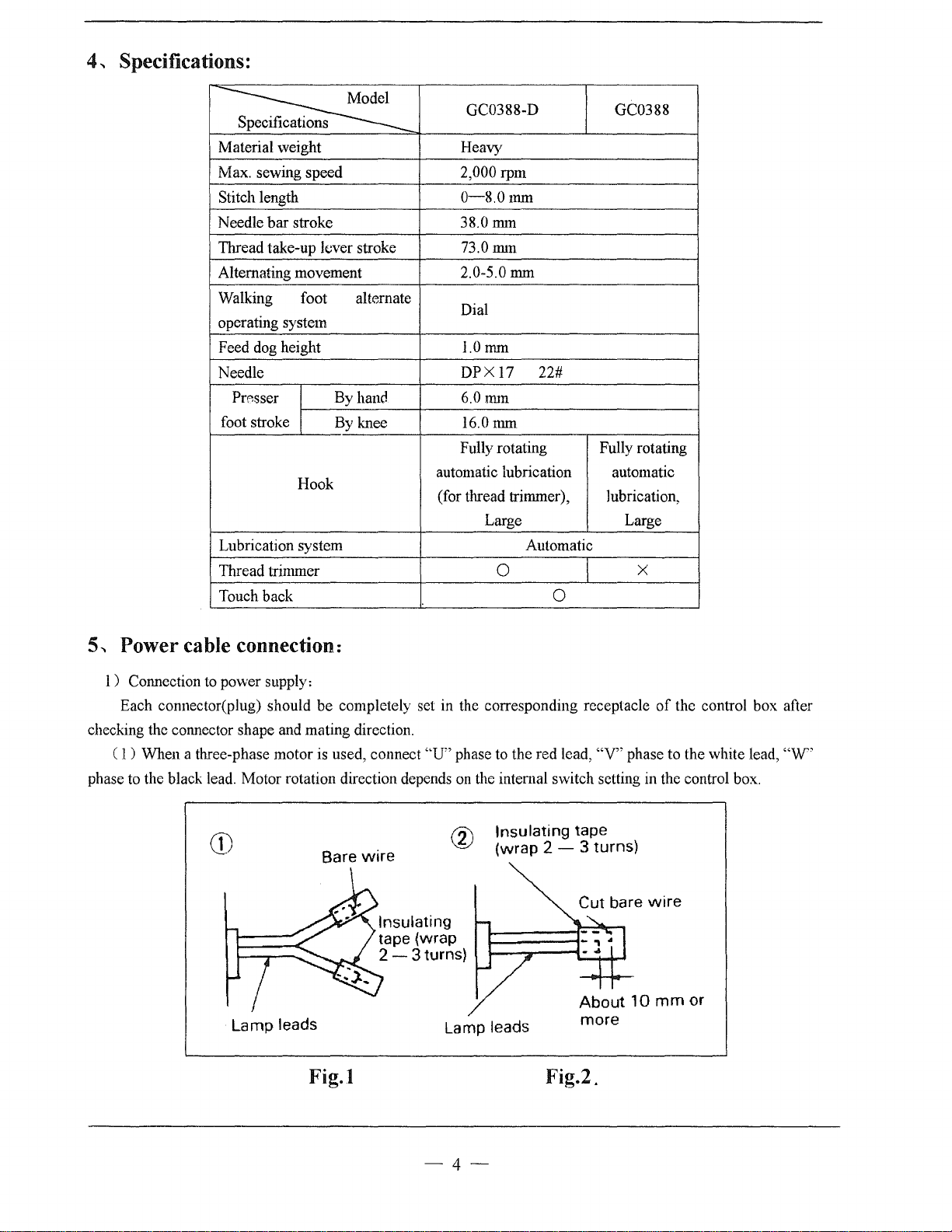
5,
Power cable connection:
1)
Connection to power supply:
Each connector(plug) should be completely set in the corresponding receptacle
checking the connector shape and mating direction.
(
1)
When a three-phase motor is used, connect
phase to the black lead. Motor rotation direction depends
Bare
wire
Lamp leads
Fig.l
''U"
phase to the red lead,
on
the intemal switch setting in the control box.
Insulating tape
(wrap 2 - 3 turns)
Lamp
leads
Fig.2.
of
the control box after
"V"
phase to the white lead,
more
"W"
-4-
Note:
The
green
wire
must
be
connected
motor.
(
2)
The appropriate power fuse capacity is as follows:
Three-phase power source:
Single-phase power source: 100-120V: 15A
2)
Lamp leads
(
1)
When installing a work lamp
control box, strip the wire and connect them appropriately insulating the connections using insulating tape.
Note:
The
power
(
2)
When a work lamp is not used, the lamp lead ends must
that the two leads do not shortcircuit.
Note:
The
work
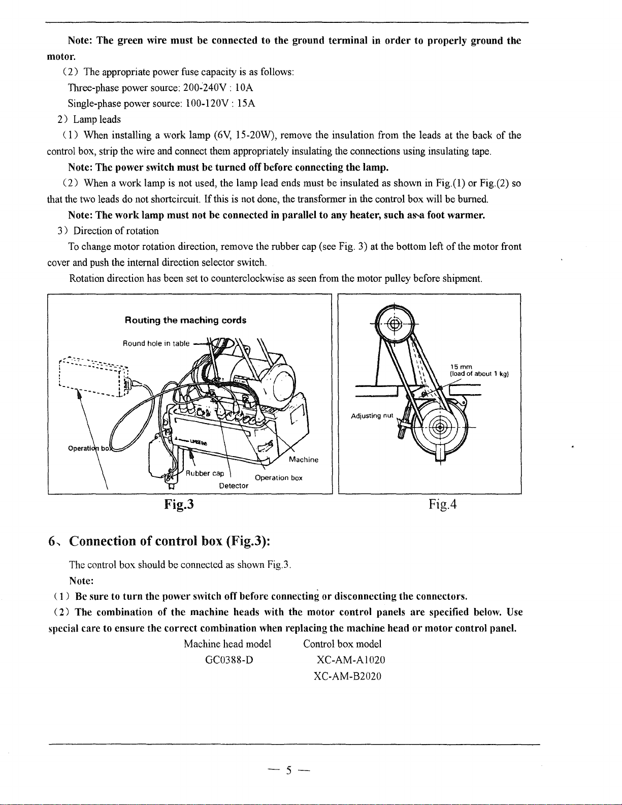
3 ) Direction
To
change motor rotation direction, remove the rubber cap (see Fig. 3) at the bottom left
cover and push the internal direction selector switch.
Rotation direction has been set to counterclockwise as seen from the motor pulley before shipment.
of
switch
lamp
rotation
200~240V
(6V,
must
be
turned
If
this is not done, the transformer in the control box will
must
not
be
: 1
connected in
to
the
ground
OA
15-20W), remove the insulation from the leads at the back
off
before
connecting
parallel
terminal
be
insulated as shown
to
any
the
lamp.
heater,
in
order
such
to
properly
in
Fig.(l) or Fig.(2) so
be
a!l"-3
foot
warmer.
of
ground
burned.
the motor front
of
the
the
Routing
Round
tlole
the
in
table
maching
cords
Fig.3
...
Connection of control box (Fig.3):
6
The control box should be connected
Note:
( 1 ) Be
(
special
sure
to
2)
The combination
care
to
ensure
turn
the
the
power
switch off
of
the
machine
correct
combination
Machine head model Control box model
GC0388-D
as
shown Fig.3.
before
heads
when replacing
connecting
with
the
or
disconnecting
motor
control
the
machine
XC-AM-Al020
XC-AM-B2020
the
panels
head
Fig.4
connectors.
are
specified below. Use
or
motor
control panel.
-5-
7
..
Installing the belt (Fig.4):
1)
Use a V-belt for sewing machine use, type
2)
To
adjust the belt tension, change the motor height by turning the tension adjust nuts so that the belt
15mm
sinks about
If the tension is too low, the speed may not be consistent in the low or medium range, or the needle
not stop in the proper position.
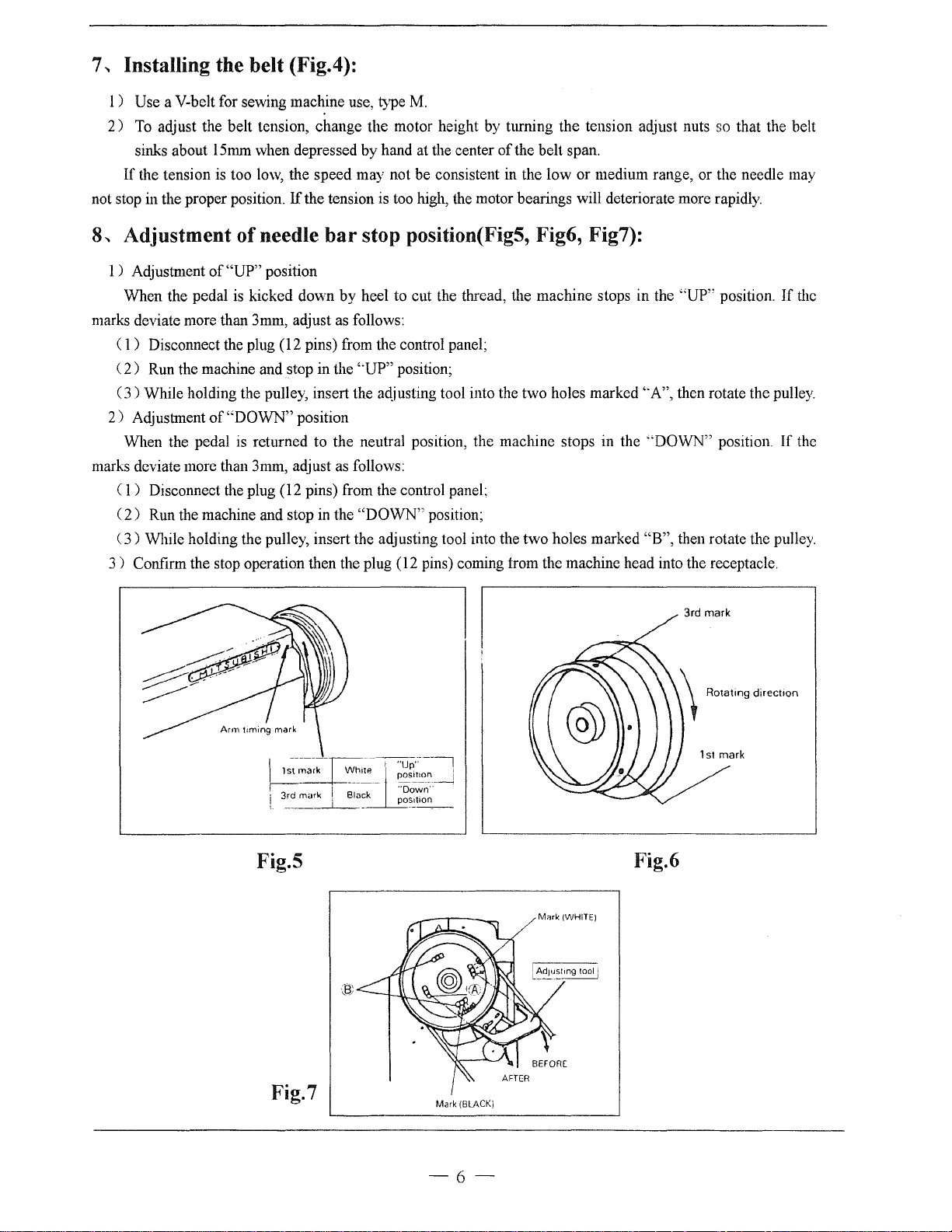
8
..
Adjustment
when depressed by hand at the center
lf
the tension is too high, the motor bearings will deteriorate more rapidly.
of
needle
bar
stop position(Fig5, Fig6, Fig7):
M.
of
the belt span.
may
1 ) Adjustment
When the pedal is kicked down
marks deviate more than 3mm, adjust
( 1 ) Disconnect the plug (12 pins) from the control panel;
2)
Run
(
(3)
While holding the pulley, insert the adjusting tool into the two holes marked '"A", then rotate the pulley.
2)
Adjustment
When the pedal is returned to the neutral position, the machine stops
marks deviate more than 3mm, adjust
1)
Disconnect the plug (12 pins) from the control panel:
(
2)
Run the machine and stop
(
3)
While holding the pulley, insert the adjusting tool into the two holes marked
(
3)
Confirm the stop operation then the plug (12 pins) coming from the machine head into the receptacle.
of
"UP"
position
by
heel to cut the thread, the machine stops in the
as
follows:
the machine and stop in the '·UP" position;
of
"DOWN"
position
as
in
the
follows:
"DOWN"
position;
"UP"
in
the "DOWN" position.
"B",
then rotate the pulley.
3rd mark
position.
If
If
the
the
I
.:
•.
:;~
I
' 1
i
3rd
marl< ,
L
_____
___l__
w.,;;_f
Black
;;;~:'
··oown··
poSition
-----
Fig.5
/Mork
(WHITE)
Fig.7
Mark (BLACK)
-6-
Fig.6
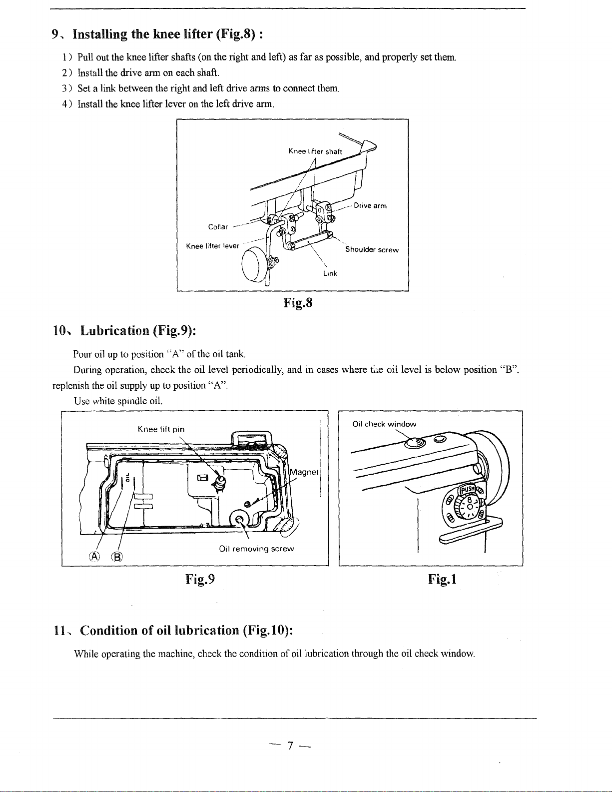
9
._
Installing the knee lifter (Fig.8) :
1)
Pull out the knee lifter shafts (on the right and left)
2)
Install the drive arm on each shaft.
3 ) Set a link between the right and left drive arms to cmmect them.
4)
Install the knee lifter lever on the left drive arm.
Collar ---··--
as
far as possible, and properly set them.
Knee lifter lever
····
Fig.8
10..
Lubrication (Fig.9):
Pour oil up to position
During operation, check the oil level periodically, and in cases where
replenish the oil supply up to position
Usc white spmdle oil.
"A"
of
the oil tank.
"A".
Shoulder screw
Link
t};e
Oil check
oil level is below position "B".
window
(~)
®
removing
screw
Oil
Fig.9
1L
Condition of oil lubrication (Fig.lO):
While operating the machine, check the condition
of
oil lubrication through the oil check window.
-7-
Fig.l
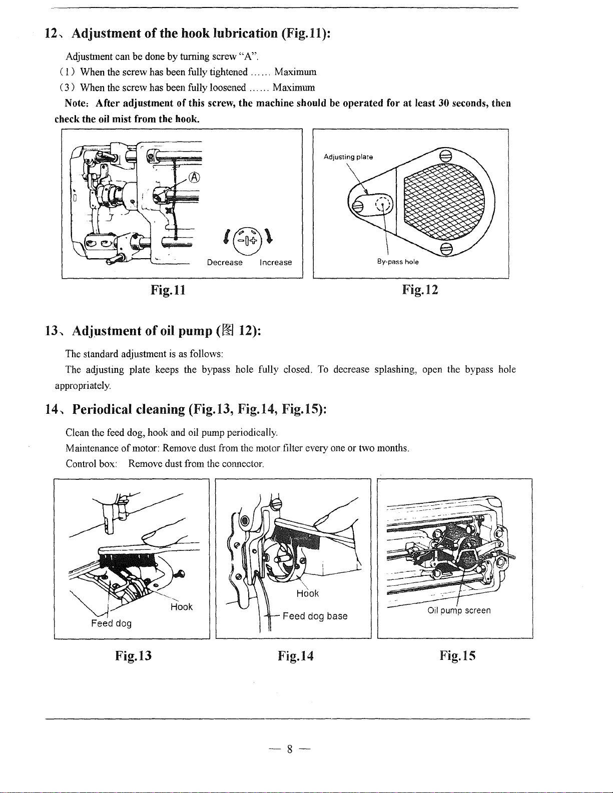
12-.
Adjustment
of
the hook lubrication (Fig.11):
Adjustment can be done
C I ) When the screw has been fully tightened . . . . . . Maximmn
3)
When the screw has been fully loosened
C
Note: After adjustment of this screw, the machine should be operated for
oil
check the
mist from the hook.
by
turning screw "A".
Decrease Increase
......
MaximUll1
Adjusting plate
Fig.11
13-.
Adjustment
of
oil pump
(00
12):
at
By·pass hole
Fig.12
least 30 seconds, then
The standard aqjustment is as follows:
The adjusting plate keeps the bypass hole fully closed.
appropriately.
14-.
Periodical
Clean the feed dog, hook and oil pmnp periodically.
Maintenance
Control box: Remove dust from the connector.
Feed
deaning
of
motor: Remoye dust from the motor filter every one or two months.
dog
(Fig.13, Fig.14, Fig.15):
"-
Hook
Hook
Feed
To
decrease splashing, open the bypass hole
dog
base
Fig.13 Fig.14
-8-
Fig.15
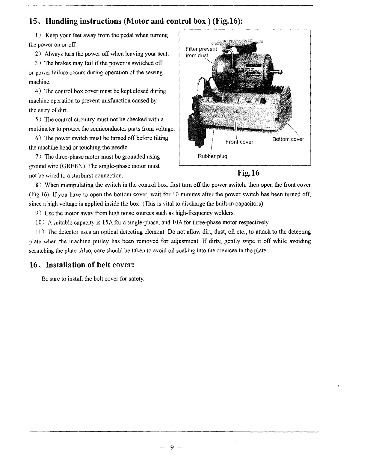
15-.
Handling instructions (Motor and control
1 ) Keep your feet away from the pedal when turning
the power on or off.
2)
Always turn the power off when leaving your seat.
3 )
The
brakes may fail
or power failure occurs during operation
machine.
4)
The control box cover must be kept closed during
machine operation to prevent misfunction caused by
the entry
multimeter to protect the semiconductor parts from voltage.
the machine head or touching the needle.
ground wire (GREEN). The single-phase motor must
not be wired to a starburst com1ection.
(Fig.l6).
since a high voltage is applied inside the box. (This
plate when the machine pulley has been removed for adjustment.
scratching the plate. Also, care should
of
dirt.
5 ) The control circuitry must not
6)
The power switch must be turned off before tilting
7)
The three-phase motor must be grounded using
8 ) When manipulating the switch in the control box, first turn
If
you have to open the bottom cover, wait for
9)
Usc the motor away from high noise sources such as high-frequency welders.
10)
A suitable capacity is 15A for a single-phase, and lOA for three-phase motor respectively.
11) The detector uses an optical detecting element. Do not allow dirt, dust, oil etc., to attach to the detecting
if
the power is switched off
of
the sewing
be
checked with a
be
taken to avoid oil soaking into the crevices in the plate.
10
is
vital to discharge the built-in capacitors).
box)
(Fig.16):
Rubber plug
Fig.16
off
the power switch, then open the front cover
minutes after the power switch has been turned off,
If
dirty, gently wipe
it
off while avoiding
16...
Installation of belt cover:
Be sure
to
install the belt cover for safety.
-9-
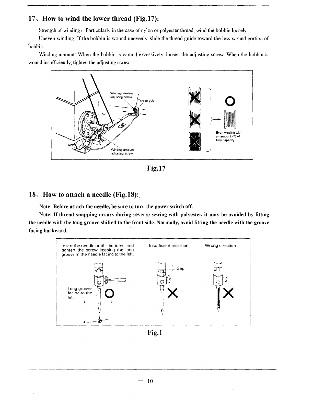
17...
How to wind the lower
thread
(Fig.17):
Strength
Uneven winding:
bobbin.
Winding amount:
wmmd insufficiently, tighten the adjusting screw.
of
winding: Particularly in the case
If
the bobbin is wound unevenly, slide the thread guide toward the le.;s wound portion
When
the bobbin is wound excessively, loosen the adjusting screw. When the bobbin
Winding tension
adjusting screw
Winding amount
adjusting screw
"-
of
nylon or polyester thread, wind the bobbin loosely.
Thread guid
0
Even winding with
an amount 4/5
fully capacity
I
Fig.17
of
is
of
18
...
How
Note: Before attach the needle, be sure to
Note:
to
attach
If
thread snapping occurs during reverse sewing with polyester, it may be avoided by fitting
a needle (Fig.18):.
turn
the power switch off.
the needle with the long groove shifted to the front side. Normally, avoid fitting the needle with the groove
facing backward.
Insert
the
tighten
groove in
needle
the
the
Long groove
facrng to
left ·
_j_
until
screw
needle facing to the left.
the
__
it bottoms. and
keeping
,
the
long
lnsuffrcient insertion
Wrong
direction
X
Fig.l
-
10-
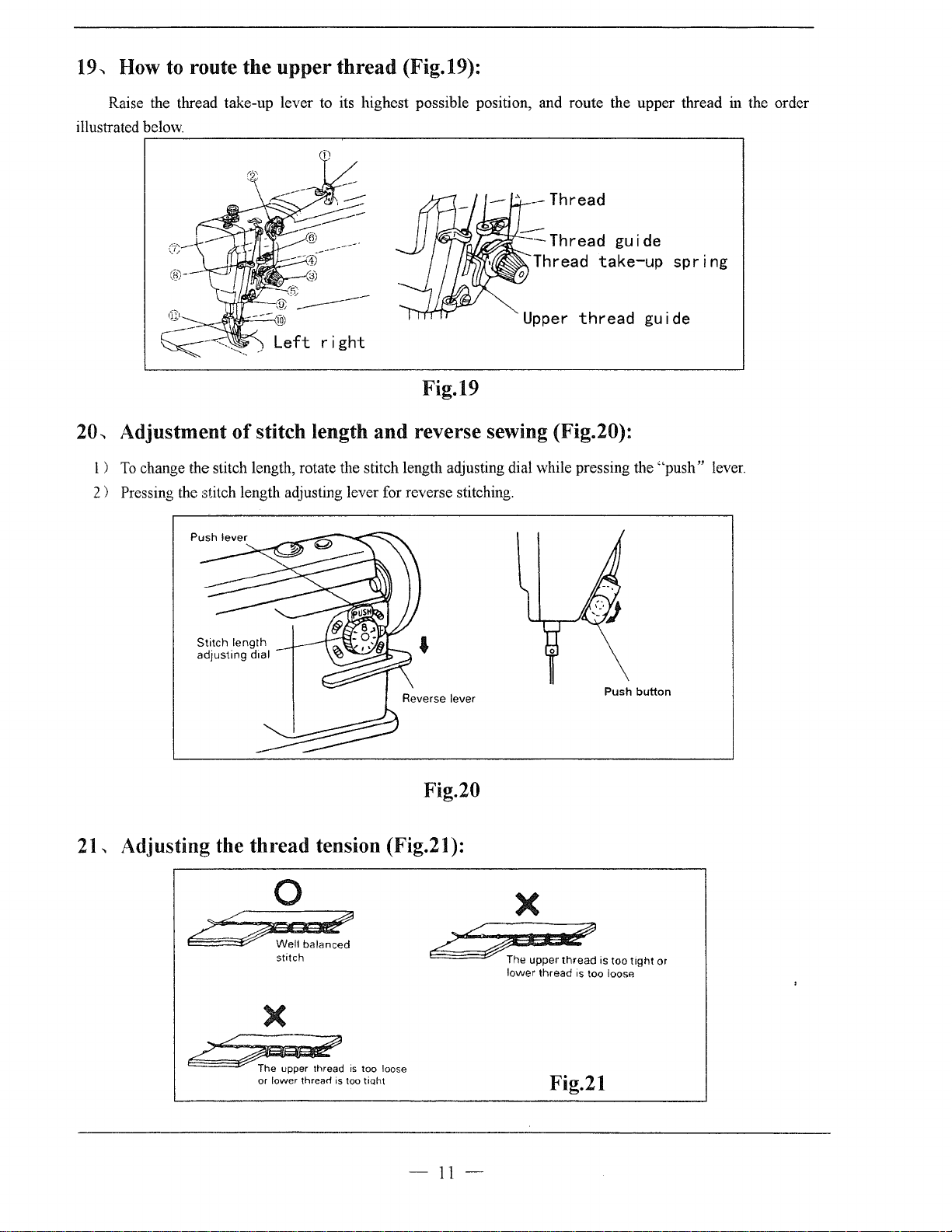
19.,
How to route the
Raise the thread take-up lever to its highest possible position, and route the upper thread in the order
illustrated below.
upper
thread
(Fig.19):
Thread
Thread guide
Thread
take-up
spring
Fig.19
20.,
Adjustment
l )
To
change the stitch length, rotate the stitch length adjusting dial while pressing the
2 ) Pressing the stitch length adjusting lever for reverse stitching.
of
Stitch
length
adjusting
stitch length
dtal
-
and
reverse sewing (Fig.20):
Upper
thread
Push button
guide
"push"
lever.
Fig.20
21.,
Adjusting the
/~
~Well
thread
0
balanced
stitch
tension (Fig.21
£/;J#!
1
):
~
X
ca~
The
upper
lower
thread
thread
X
2:2~.
he upper thread
or lower threarl
IS
is
too tioht
too loose
Fig.21
-
11-
is too
is
too
loosP.
tight
or
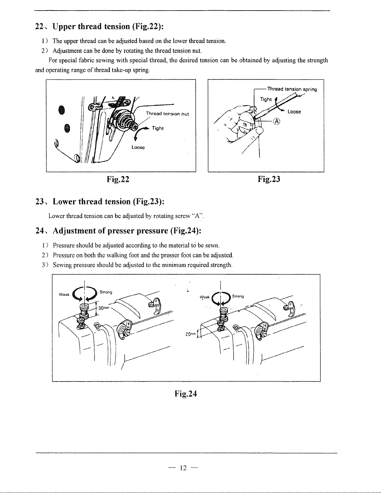
22
...
Upper
1 ) The upper thread can be adjusted based on the lower thread tension.
2 ) Adjustment can be done
For special fabric sewing with special thread, the desired tension can
and operating range
thread tension (Fig.22):
by
rotating the thread tension nut.
of
thread take-up spring.
be
obtained by adjusting the strength
Thread tens1on
loose
nut
Fig.22
23-.
Lower
Lower thread tension can be adjusted by rotating scre\v "A".
24
...
Adjustment of presser pressure (Fig.24):
1 ) Pressure should be adjusted according to the material to be sewn.
2)
Pressure on both the walking foot and the presser foot can be adjusted.
3)
Sewing pressure should be adjusted to the minimum required strength.
thread
tension (Fig.23):
Fig.23
2Qmm
Fig.24
-
12-
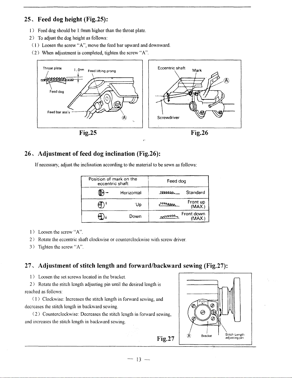
25-.
Feed dog height (Fig.25):
l)
Feed dog should
2)
To
adjust the
( 1 ) Loosen the screw
(
2)
When aqjustment is completed, tighten the screw "A".
be
l.Omm higher than the throat plate.
dog
height as follows:
"A",
move the feed
bar
upward and do""nward.
Throat plate
"~"'T
Feed dog
26" Adjustment
If
necessary, adjust the inclination according to the material to be sewn as follows:
.
Qmm
1
Feed
lifting
prong
\
Fig.25
of
feed dog inclination (Fig.26):
Position of mark on the
eccentric
~-
€D'
ED•
shaft
Horizontal
'Up
Down
Eccentric shaft
I
I
~
I
~
I
~
I
Feed dog
Front
Fig.26
Standard
Front up
(MAX.)
down
(MAX.)
1 ) Loosen the screw "A".
2 ) Rotate the eccentric shaft clockwise or counterclockwise with screw driver.
3)
Tighten the scre\v "A".
27" Adjustment of stitch length and forward/backward sewing (Fig.27):
1 ) Loosen the set screws located
2 ) Rotate the stitch length adjusting pin until the desired length
reached
decreases the stitch length in backward sewing.
and increases the stitch length in backward sewing.
as
follows:
(
l)
Clockwise: Increases the stitch length
(
2)
Counterclockwise: Decreases the stitch length in forward sewing,
in
the bracket.
in
forward sewing, and
is
Bracket
Fig.27
-
13-
'
St1tch
Lengt~l
adjusting pin
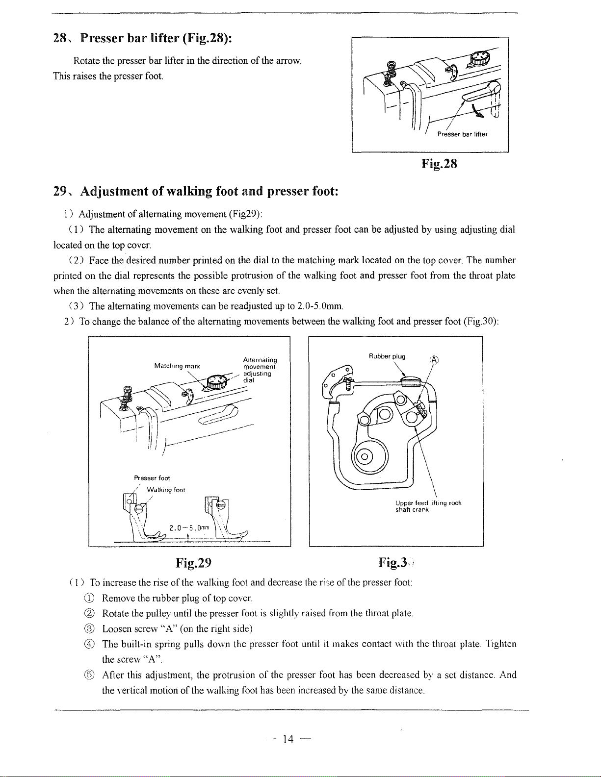
28.,
Presser
bar
lifter (Fig.28):
Rotate the presser
This raises the presser foot.
29.,
Adjustment
l)
Adjustment
( 1 ) The alternating movement on the walking foot and presser foot can
located on the top cover.
(
2)
Face the desired number printed on the dial
printed on the dial represents the possible protrusion
when the alternating movements on these arc evenly set.
(
3)
The alternating movements can
2)
To
change the balance
bar
lifter in the direction
of
walking foot and presser foot:
of
alternating movement (Fig29):
be
readjusted
of
the alternating movements between the walking foot and presser foot (Fig.30):
of
the arrow.
to
the matching mark located on the top cover. The number
of
the walking foot and presser foot from the throat plate
up
to
2.
0-5.
Omm.
Presser bar lifter
Fig.28
be
adjusted by using adjusting dial
Match1ng
mark movement
,c-,~~~'"""
~~~~~;;;b
I
.---1-
II'
I .
i ! i
~---------
1.
t I
Presser foot
~,,,,,
I •
\
'.
\\
~-~-~--~--~-
( 1 )
To
increase the rise
CD
Remove the rubber plug
® Rotate the pulley until the presser foot
® Loosen screw
0)
The built-in spring pulls down the presser foot until it makes contact
the screw "A".
@ After this adjustment, the protrusion
the vertical motion
2
0-5
Fig.29
of
the walking foot and decrease the
"A"
(on the right side)
of
--~----
]L
' \
Qmm
\\
\:·
of
top cover.
the walking foot has been increased by the same distance.
Alternating
7?_
is
of
Rubber plug
Upper feed
shah crank
liftmg
rock
Fig.J,,
ri
;e
ofthe
presser foot:
slightly raised from the throat plate.
vvith
the throat plate. Tighten
the presser foot has been decreased by a set distance. And
-
14-

C
2)
As
a contrary case ( 1) , to decrease the rise
of
the walking foot and increase the rise
follows:
Fist, rotate the pulley until the walking foot
Finally, tighten screw "A". This decreases the rise
3)
Installing the feed regulator bracket (Fig.31
Note:
If
the feed regulator bracket
is
slightly raised from the throat plate. Next, loosen screw "A".
of
the walking foot.
):
is
poorly positioned, the resultant alternating movements may be
too short or long, causing defective machine operation.
C 1 ) Set the clearance between special screw
located on the regulator stud and the side wall
machine arm to 26.5mm as Fig.31.
2)
With the feed regulator stud held as explained
(
1)
is step (
above, adjust the feed regulator bracket.
This adjustment should insure a clearance
of
pin
"B"
between the periphery
located on the feed
regulator bracket and the top cover motmting face
located on the arm. Tighten screw
"C".
of
"A"
of
the
12mm
of
presser foot
r-------------------------------------~
Feed regulator bracket
as
4)
Feed pitch adjustment
of
The ratio
the upper feed amount
to the lower feed amount
to
1:
1.
However, the walking foot feeding an10unt can be
of
walking foot (Fig.32):
(of
the \valking foot)
(of
the feed dog) has been adjusted
increased or decreased depending on the operating conditions..
Loosen the nut located on the upper feed rock shaft
of
crank (left), and shift to adjust the position
the pivot
bracket upward or downward.
Upper
position~Fecd
Lower
position~
pitch-Small
Feed
pitch-Large
Nut
Fig.31
---
Fig.32
Upper feed rock
crank (Left)
shah
-
15--

30
...
Adjustment of feed timing (Fig.33):
1 ) The standard position
feed cam and eccentric feed lifting
of
the eccentric
can1
are
illustrated to Fig.33
2)
Open the top cover,properly slide the
eccentric ring to adjust the position.
3 ) eccentric feed
by
removing the rubber plug located on the
cam can also
be
adjusted
top cover. In the latter case, however, the
built-in bevel gear is concealed; care should
be taken when adjusting.
31,
Adjustment
1)
The thread trimmer mechanism illustrated as Fig.34.
of
thread
trimmer
1
st
screw
Upper eccentric feed
lifting cam
Upper
Top cover
mechanism:
shaft
Bevel gear for
upper
Rubber
Fig.33
plug
shaft
Eccentric
feed cam
Thread guide ,
Fixed blade ,
Movable knrfe (ref!)
,,_,_
Knrfe drrvrng
crank
[_~_')I~_
y
I
I
Knrfe driving
shaft
base
unit_]
Cam follower
crank (1)
Twist spring
Colla\\
Thread trrmmer
cam
\
Cam follower
crank (2)
Fig.34
\
\\
Drive lever
L
Thread
..
------
',
, Stopper
Stopper
plate
trimmer
·-------·--------··-------··-
Flexrble wrre
Twrst sprrng
solenoid
unit
j
-16-

2)
Relation between the fixed blade and movable knife (left) edge:
C
1)
The standard position is illustrated as Fig.35.
(2)
The distance between the fixed blade and movable knife is 0.3mm.
(3)
The correct position
of
fixed blade bracket or fixed blade
®
I
r-..-----+---
(knife edge)
can
be
adjusted according to Fig.35.
0.
3mm
Movable knife (left)
1
l----11
3)
Knife driving shaft:
(
1)
The standard position is illustrated as Fig.36.
(
2)
When assembling, the knife driving shaft must first be put through the drive arm.
C
3)
Cam follower crank 1 must be positioned as illustrated
the knife driving shaft.
0
Fixed blade
bracket
unit
( 4 ) The stopper must be secured on the recess in such a
smoothly rotates in the shaft direction.
Coil
spring
Cam follower
1 Cam
crank
\
Fixed
Fig.35
follower
0
0
blade
to
the right, and secured on the recess located on
way
that the knife driving shaft
crank 2
is
snug and
Bush1ng
\ J
87.5mm
~-
-----------
Knife
shaft
driving
','\
Stopper
Fig.36
4)
Installing the thread trimmer solenoid unit (Fig.3
( I ) Operation stroke
a.
Standard operation stroke is 6.0mm.
b.
This stroke can be adjusted by using nut ''A".
( 2 ) Installing the unit:
a.
The unit can be mounted by using screws
b.
Clearance
stopper nut
c.
In
such a situation, activating the solenoid should create a clearance
of
the thread trinm1er solenoid:
of
l.Omm must be insured between the driving lever and cam follower crank 2 with
"A"
made contact with solenoid.
-
7):
"B"
17-
and "C".
of
0.5mm between cam

follower crank 1 and 2. This situation is standard. To
bracket in the direction
mm
6
5)
Installing the thread trimming
(
1)
Face the 2nd timing
(
2)
With the thread
contact with the roller. Then, secure the cam.
(3)
With the thread trimmer solenoid deactivated, allow the
position. This should create a clearance
standard.
trimmer
of
the arrow as illustrated,
cam
(Fig.38):
mark
"A"
(GREEN)
solenoid activated, rotate the thread trimmer
of
Matching
meet
this standard, slide
if
adjustment is needed.
the
®@
Cam follower
crank 2
follower
Cam
crank 1
mounting
bracket
o.smm
Fig.37
located on the pulley to the matching mark on the arm.
cam
forward until the
cam
follower crank 2 to return to its original
0.5mm-l.Omm
mark
between
A
the
cam
and roller end .This distance
\
solenoid mounting
cam
makes
is
Thread
trimmer
cam
follwer
\
\
\
0
\\
'-.....___
----~
Hook
shaft
0.
6mm
//"
Roller~----~.de
~
)Q/
crank
2/-.?~
\,
Knife
~
~
·
)!
u!
driving
0.
5-1.
cam
,~-'ljr·
·----Ju.
lht__
..
Omm
~
:
w~p
shaft
Fig.38
-
18-

6)
Adjustment
1)
Position
(
of
knife engagement (Fig.39):
of
movable knife (left) and fixed blade:
See the Fig.39, the standard distances from the needle center are 7.5mm and 5mm from the movable knife
(left) and fixed blade respectively:
of
( 2 ) Adjustment
knife engagement:
With the solenoid activated, turn on the machine. This rotates the thread trimming cam which rotates the
movable knife (left) When the movable knife (left) has
moved to its farthest distance, the standard
the blade
by
is
1.5mm-2.0mm. The engagement can be adjusted
properly mounting the drive arm.
3)
Adjustment
(
a.
If
a thread is poorly cut, particularly
of
knife engagement pressure:
engagement
w·hen
it
is
of
thick,
Movable
knife (left) 7.
' '
Smm · Smm
Fixed blade
/@
1
slightly increase the engaging pressure. This should solve the
problem.
b.
The engaging pressure can be adjusted in this way:
Loosen lock nut
"B"
and adjust it
by
using adjusting screw "A".
Knife driving crank
I
.5-2
.Qmm
Fixed blade
r;fJ
Movable
Movable knife (left)
knife (left)
Fixed blade
Fig.39
-19-

A.ARM BED AND ITS ACCESSORIES
-20-

A.ARM BED AND ITS ACCESSORIES
Fig.
No.
AOl
A02 HA300B2110 Rubber plug
A03
A04
A05 H6029B8001
A06 HA307B0673
A07 HA700F2100
A08 H6017B8001
A09 H6022B8001
AlO
All
A12 H6025B8001
A13
Al4
Al5
Al6
A17
Al8
A19
A20
A21
A22
A23
A24 HA300B2100
A25
A26 HA100B2220 Leg
A27
A28 HA710B0672
A29 HA112B0693 Thread tension disc
A30 HA710B0673 Thread tension stud
A31
A32
A33 HA600B2050 Thread guide
A34
A35
A36
A37
A38
A39 HA500C2060 Thread guide
A40 HA115B7011
A41
A42
A43
Part No.
Description
HA300B2090 Rubber plug
HA300B2170
H6028B8001
Screw
Arm side cover
Gasket for
arm
side cover
Rubber plug
Screw
Thread guide
Coil spring for upper feed lifting
H6023B8001
H431040060
Stopper pin for upper feed lifting
Set
screw
Dial for upper feed lifting
H6026B8001
HA309B0069
HAlllG0683
H6015B8001
H6016B8001
H6030B8001
H6031B8001
H6032B8001
Plate for upper feed lifting
Oil
check window
Screw
Top cover
Gasket for top cover
Rubber plug
Rubber plug
Rubber plug
H6020B8001 Upper feed lifting regulator
HA600C2020 Thread take-up cover
HA100B2110 Set screw
Rubber plug
H005008060 Spring washer
HA710B0671
Pre-tension adjusting nut
Thread tension spring
HA710B0674 Thread guide
HA106B0676 Screw
screw
HA300B2080
Set
HA300B2130 Screw
H2000B2040 Cloth guide plate
HA307B0674 Rubber plug
HA114I0674
Screw
0-ring
HA310B0703
HA806B0671
Thread tension regulator bushing
Thread take-up spring
H6037B8001 Thread releasing pin
cam
Ci
00
I
00
00
('")
00
('")
0
~
4
1
0
u
0
4
<1>
8.8
1
<1>
5.7
Remarks
4 4
1 1
1
1
3
3
<1>
11.8
1 1
SM11/64(40)x7
1 1
1
1
1
1
2 2
GB/T80M4x6
1 1
1 1
1 1
8 8
SM11/64(40)xl2
1 1
1
1
2
2
1
1
1
1
1
1
1
1
1 1
SMll/64(40)x5.5
1 1
3
3
1 1
GB/T936
3
3
SM11/64(40)
1 1
2 2
1 1
SM11/64(40)x31
1 1
2
2 SM9/64(
40)x6
1 1
1 1
2
SM15/64(28)x6.8
2 SM11/64(40)x5.5
1 1
1 1
1 1 SM9/64(40)x4.5
1 1
1 1
SIS
1 1
1 1
1 1
-21-

A.ARM BED AND ITS ACCESSORIES
Fig.
No.
A44
A4S
A46
A47
A48 HA11SB7010 Thumb nut revolution stopper
A49
ASO
• ASl
AS2 HA124B0713 Screw
AS3
AS4
ASS
AS6
AS7
ASS
AS9
A60 H6008B8001 Arm 1
A61
A61
A62
A63
A64
Part
No.
HA806B0673 Thread tension stud
HA310B070S Thread tension disc
HA310B0702 Thread tension releasing disc
H2206B0671 Thread tension spring
HA310B0701 Thumb nut
HA11SB0708
HA607B0671 Thread guide
HA124B0712
H6812B8001 Slide plate
HASOOB2030
H2000B20SO
HA700B2030
HS341B8001
H6013B8001
H6010B8001 Bed
H6406B8001 Bed
H6409B8001 Arm bed cover
H6410B8001 Gasket for
HA300B2160 Screw
Screw
Plate spring for slide plate
Needle plate
Screw
Screw
Screw
Face plate
arm
Description
bed cover
Q
00
00
(<)
0
~
1
2
1
1
1
1
1
1
2
1
1
1
2
2
1
1
1
00
00
(<)
0
Remarks
~
1 SM1/4(40)x49
2
1
1
1
1
1 SM9/64(40)x6
1
SM3/32(S6)x2.2
2
1
1
1
SM11/64(40)x8.8S
2
SM11/64(40)x20
2
1 SM11/64(40)x26
1
1
1
1
1
1
SM11/64(40)xl2
s
-22-

B.SEWING
MECHANISM
24
3 -
4
5
.1)
"'
6~
7
11
39
40
'1
43
-23-

B.SEWING MECHANISM
Fig.
No.
BOI
B02 H2009B0067 Needle
B03
B04 H6006C8001 Needle bar bushing (lower)
BOS
B06
B07
B08
B09 HA700H2040
BlO
B
BIZ HA300C2030 Screw
Bl3
Bl4
BIS
Bl6
Bl7
Bl8
Bl9
B20 H6011C8001 Upper shaft bushing (upper)
B21
B22 H6016C8001 Upper feed rock crank (left)
B23
B24
B25 HA3411D308
B26
B27
B28 HA112D3012
B29 H6020C8001
B30 H6019C8001
B31
B32
B33
B34
B35 HA113D2112 Upper shaft gear
B36 HAII3D2122 Vertical shaft gear (upper)
B37
B38
B39 H6022C8001 Vertical shaft
B40 HA600D2010 Vertical shaft bushing (lower)
B41
B42 HA113D2212
1343
Part No. Description
HA300B2090 Rubber plug
bar
bushing (upper)
H6005C8001
H2000G2020 Thread guide
H2000G2030
HA100C2170 Set
HA100C2020 Screw
HA804H0651
11
H6007C7101 Thread take-up lever assay
HA100C2200 Slide block
H2205C0661
HA307C0662 Set screw
H6023C8001 Needle bar crank
HAIOOC2060 Screw
HA705C0662
HA100C2070 Set screw
H6013C8001 Upper feed lifting cam
H6015C8001 Balance weight
HA100D2040 Upper shaft bushing (middle)
HA108G0661
HA105D0662 Screw
H6018C8001 Upper feed lifting cam (rigbt)
H6021C8001 Upper shaft bushing (right)
HA306D0066 Oil seal
HA108C0663 Screw
HAIOOD2110 Vertical shaft hushing (upper)
HA 1
(X)C2020
HA113D2222 Vertical shaft gear (lower)
HA
104DOo52 Ruhher plug
Needle bar
Needle
screw
Felt
shade cap
Oil
Needle bar connecting link guide
0-ring
Screw
Collar for upper shaft
C-type retaining ring
Crank rock
Upper feed rock crank (right)
Screw
Lower shaft gear
Q
00
I
00
00
("'")
00
("'")
0
0
~
~
1 1
1
1
1 1
1
1
1 1
1
1 1 SM1/8(44)x4.5
1
1
DPxl7
1
SM15/64(28)x10
1
1
#22
1 1
1 1
2
2 SM11/64(40)x8
1
1
1 1
2 2
SM1/4(40)x6
1 1
1
1 SM9/32(28)xl3
1
1
1
1 SM9/32(28)xl4
1
1
1
1
1
1
1 1
1 1
1 1 SM 15/64(28)x7
1 1
2 2 SM1/4(40)x4
1 1
1
1
1
1
1
20
1
1
1
1
1
8 8 SM1/4(40)x7
1 1
I I
1 1
2 2
1
SM15/o4(28)xl u
1
1 I
1 1
1 1
I I
Remarks
-24-

B.SEWING MECHANISM
Fig.
No.
B44
B45
B46
Part No.
Description
H6010C8001 Upper shaft
HA704C0653
Felt
HA7121Cl04 Oil amount adjusting pin assay
Q
I
00
00
("<")
0
~
1
1
1
00
00
("I")
0
~
1
1
1
Remarks
-25-

C.FEEDING AND FEED
3 .
~
4
LIFTING & LOWER
SHAFT MECHANISM
14
15
12 13
\~
(/
11
~
~
~
-..........
rJ
~-
25
23
48
27 28
47
r§\~/)
Y/!J--44
~
45
-26-

C.SEWING MECHANISM & FEED ROCK
Fig.
No.
COl
C02
C03 HA104G0011 Feed rock shaft crank 1 1
C04 HA104G0012 Screw
cos
C06 HA104G0654
C07 H6005D8001 Feed dog 1 1
C08 HA705J0021 Feed bar assay 1
C09 Hl204D0651
C10 HA111G0683 Screw 1 1 SM11/64(40)x12
C11
C12
C13
C14 H6012D8001 Upper feed rock shaft 1 1
Cl5
C16
C17 HA800F2020
Cl8
Cl9
C20 H6006D8001 Feed rock shaft 1 1
C21
C22 HA105D0662 Screw
C23 HA100G2040
C24 H007009150 C-type.retaining ring 1
C25
C25 HA600E2080 Bobbin case 1
C26 HA600E2060 Bobbin 1 1
C27 HA100E2150 Screw 1 1 SM11/64(40)xl0
C28
C29 H2200C2050 Rotating hook 1
C29
C30
C31
C32 HA 700E2030
C32
C33
C33 H6404D8001 Bushing for hook shaft (left) 1
C34
C35
C3G
C37
C38
C39
Part
No.
HA300C2030 Screw 1 1 SM11/64(40)x8
HA705J0654
HA104G0656
H6010D8001
HA300C2030
H6011D8001
H4722G8001 Square block 2 2
HA113F0684 Screw 1
H6008D8001 Feed rock shaft crank (right) 1 1
H6009D8001
HA105D0661
HA900E2030
H2100E2010
HAGOoE0066
HAllllE104
HA1111E204 Oil felt for hook shaft 1
HA106E0071 Oil
HA 704BOo54 Bushing for hook shaft (left) 1
HA704B0653
H6015D80lll
HA305E06o2
HA305E0661
HA311E067l
HA 1
OOC2020
Shaft for feed
Washer 1 1
Screw
Feed lifting rock shaft fork
Upper feed rock shaft 1
Screw 1 1
Connecting
Screw
Pin
Collar
Bushing for feed rock shaft
Bobbin case
Hook positioner
Rotating hook
Screw 1
Oil
Bushing for hook shaft (middle) 1 1
Hook shaft 1 1
Screw 2
Collar for hook shaft 1
Bushing for hook shaft (right)
Screw
rod
for feed rock shaft
seal
seal
Description
bar
(eccentric) 1 1
for upper feed 1 1
LOWER
Q
I
00
00
("')
0
~
2
2 2 SM1/8(44)x6
1 1
1 1
1 1
2 2
4
1
1
1 1
1
1 1
1
SHAFT
00
00
("')
0
u
0
2
1
1
1
4 SM1/4(40)x4
1
1
1
1
1
1
2
1
1
Remarks
SM3/16(28)x 12
SMll/64(
SM15/64(28)x8.5
SM
GBIT894.1
SM3/16(32)x9.7
SM15/64(28)x4.5
SM15/64(28)xl0
40)x8
15/64(28)x 13.5
15
-27-

C.SEWING MECHASISM & FEED ROCK LOWER SHAFT
0
00
oO
Fig.
No.
C40
C41
C42
C43
Part
No.
HA300E2100
Plunger
HA300E2110 Coil spring
HA300E2040
Guide plate
HA104F0654 Screw
DescriptiOn
C44 HA705K0661 Feed lifting rock shaft crank (right)
C45
HA104G0012
C46
HA100G2070 Pin
C47
H6013D8001 Feed lifting rock shaft
C48
HA!OOG2120 Bushing for feed lifting shaft
C49
HA100G2130 Washer
Screw
C50 HA710E0692 Screw
C51 HA710E0691 Thread trirmner
cam
00
(")
0
~
1
1
1
1
1
2
1
1
1
1
2
1
00
(")
0
u
0
1
1
1
SM15/64(28)x10
I
1
2 SM3116(28)xl2
1
1
1
1
SM1!4(40)xl0
Remarks
-28-

D.STITCH
REGULATOR
MECHANISM
5
\
49 '
\M
,p
\
~6
48
______.o
47 45
-29-

D.STITCH LENGTH MECHANISM
Fig.
No.
DOl
D02 HA10SD0662
D03
D04 HA100B2110 Screw
DOS
D06 H6007E8001 Bracket pin
D07 H6008E8001 Pin
DOS
D09
DlO
D11
D12
D13
D14 HA3411D308
DIS
D16
D17
D18
D19
D20 H6009E8001 Feed regulator
D21
D22
D23
D24
D2S
D26
D27
D28
D29
D30 HA720F0681 Screw
D31
D32
D33 HA7421F120 Dial
D34
D3S
D36
D37 HA113F0683 Screw
D38 HA104F06S4
D39
D40 HA100F2110 Spring washer
D41
D42 HA113F3022
D43
Part No.
HA108G0661 Collar for reverse
Screw
HA100G2040
HA100C2020 Screw
H6006E8001 Reverse bar
H4723G8001
HA300C2030 Screw
HA700B2120 Rubber plug
HA100F2040
HA704B06SS
H6012E8001 Washer
H007013040 E-type ring
H6010E8001 Link
H6013E8001
HA113F0684
H6018E8001
HC01360
H601SE8001 Bracket
HA100E21SO Screw
HA100F2090 Spring for stopper pin
HA700F2030 Stopper pin
HA113F3022
H6017E8001 Feed regulator pin
HA109F0674
HA720F0687 Coil spring
HA720F0683 Stopper pin releasing lever
H220SD0661
HA720F068S Bushing
HA720F0686
HA309F0671
H3008F0671 Feed reversing lever shaft
H6020E7101
Bushing for reverse bar
Guide plate
Pin
Bushing for feed regulator
Screw
Pin
Screw
Spring,retainer
0-ring
0-ring
0-ring
bar
Plate
for stitch length
Screw
Screw
Feed reversing lever
0-ring
Crank for feed reversing lever
Description
bar
0
00
00
00
("')
00
("')
0
0
u
d
~
1 1
2
1 1
1 1 SM11/64(40)xS.5
1
1 1
1 1
1 1
2 2
6 6 SM11/64(28)x8
1 1
1 1
1
1
2
2 2
1 1
2 2
1
1 1
1 1
1 1 GB34S2.1 36
1 1
4 4 SM11164(40)x10
1 1
1 1
1
1 1
1 1
1 1
1 1
1
1 1
1
1 1
1 1
1 1 SM3116 (28)x6
2 2
1 1
1 1
1
1 1
1 1
SM1/4(40)x4
2
SM 1S/64(28)x
1
1
1 SM1S/64(28)x7
2
GBff896
SM1S/64(28)x8.5
1
1
1
1
SM3/l6(28)x
SM1S/64(28)xl0
1
Remarks
4
18
10
.S
-30-

D.STITCH LENGTH MECHANISM
Fig.
No.
D44
D45
D46
D47
D48
D49
D50
Part No. Description
HA100F2130 Screw
H6023E8001
HA800F2010
HA800F2020 Screw 1
HA806C0675
HA806C0674
H6011E8001
Spring
Spring holder 1
Spring holder 1
Coil spring 1
Link for reserve feed
0
00
00
("')
0
~
1
1 1
1
00
00
("')
0
~
SM15/64(28)x 14.5
1
1
SM15/64(28)xl3.5
1
1
1
Remarks
-31-

E.UPPER FEED
ROCK
SHAFT
'IECHA~ISM
2
1?
15
13
21
22 23
-32-

E.TOP FEED MECHANISM
Fig.
No.
EO!
E02
E03
E04
E05
E06
E07
E08
E09
ElO
Ell
E12
E13
E14
E!5
E!6
E!7
E!8
E!9
E20
E21
E22
E23
Part
No.
H6006F8001 Upper feed rock shaft crank (left)
H6017F8001 Screw
HA!OOB2110
H6008F8001
H2013N0067
H2013J0065
H2121I0065
H6007F8001
HA!08GD66!
HA105D0662 Screw
H6018F800!
H6013F800! Upper feed rock shaft crank (right)
H2010J0066 Nut
H6014F800! Feed driver connecting rod
H2012N0066
HA3411D308 Screw
H6010F8001 Hinge pin
H6015F800! Feed connecting lever
H2004J0662 Screw
H6016F8001
H2004J0067 Screw
HA100I2050 Spring washer
H2004J066! Feed
Screw
Bushing for upper feed rock shaft crank
Nut
Washer
Feed connecting slick block
Upper feed rock shaft
Collar
0-ring
Screw
Walking foot connecting rod
arm
Description
M
I
2
2
2
1
1
1
1
1
2
1
1
1
1
1
1
I 1
1
2
1
2
2
1
H
1
2
SM15/64(28)x!8
2 SM11/64(40)x5.5
2
1 SM1/4X24
6
1
1
1
1
SM114(40)x4
2
1
1
1 SM9/32X28
1
1 SM9/32(28)x7
1
SM15/64(28)x7
1
SM114(40)x5
2
1
2
SM9/64(40)x7
2
3.5
1
Remarks
-33-

F.
UPPER FEED
3
1
LIFTING
ROCK
SHAFT MECHANISM
18
17
,.~37
38
4i
46 45
1--35
®
36
i--39
k40
1~k·
~
~
.
tt--------'42
47 44 48
-34-

F. UPPER FEED LIFTING
Fig.
No.
Part No.
ROCK
Description
SHAFT MECHANISM
Q
00
I
00
00
(")
00
(")
0
0
u
~
CJ
Remarks
H6005G8001
FOl
F02 HAIOOB2110 Screw
H6006G8001
F03
F04 H6007G8001
FOS
H6009G8001 Upper feed lifting rock crank
F06
HA800F2020
F07
H6010G8001 Upper
H6011G8001
F08
F09
H6039G8001
H6013G8001 Upper
FlO
HA7311C606 Screw
F11
H6014G8001
F12
F13
H6015G8001 Crank for upper feed lifting rock crank
Fl4
H007009100 C-type ring
F15 H6016G8001 Pin
Fl6
H6020G8001
HAIOOG2040 Bushing for upper feed shaft
F17
Fl8
H6019G8001 Upper feed regulator shaft
Fl9
H6021G8001 Spring
HA108G0661
F20
F21
HA105D0662 Screw
H2004J0662 Screw
F22
F23
H6023G8001 Link for feed lifting rock shaft
H007013060 E-type ring
F24
H6022G8001 Pin
F25
H6024G8001
F26
F27
H6027G8001 Link
H6028G8001 Pin
F28
F29 H6029G800 1 Stud screw
F30 H6030G8001 Bell crank support
F31
H6040G8001
F32
H6031G8001 Bell crank support shaft
F33
HA110D0672 Screw
HA300B2110
F34
H201010065 Thumb screw
F35
H20lOJOOo6
F3o
H0032G8001 Presser regulating bracket
F37
F38
HA300C2030 Sere\\
Ho038G800 1 Spting
F39
F40
H6034G7101
F41
H6037G8001
F42
Ho036G8001
F43 H603
3CT800
Upper
feed lifting rock shaft
Bushing for upper feed lifting rock shaft (left)
Bushing for upper feed lifting rock shaft (right)
Screw
feed lifting rock crank shaft
Link
Screw
feed regulator bracket
Shaft for upper feed lifting rock shaft
Cam follower
Collar
Bell crank
Nut
Rubber plug
Nut
Spring guide bar assay
Bushing for walking foot guide link
Walking foot guide link
1
Spring guide bar holder
I
I
4
4
SMIII64(40)x5.5
I I
I 1
1 1
1
1
SM15/64(28)xl3.5
1 1
1 1
2 2
SM11/64(40)x3.8
1 1
4 4
1 1
1
1 1
1 1
I
2 2
I I
I I
I 1
2 2
2 2 SMI/4(40)x5
I 1
2 2
I I
1 1
I 1
I
I I
1 I
I 1
I I
I
1
1 I
1 1
1
2 2
1
1 1
I I
I
1 1
SM11/64(40)x15
1
GB/T894.1
1
SMI5/64(28)x10
SMI/4(40)x4
GB/T896 6
I
SM 15/64(28)x5
SMIS/64(28)
I
SM
15/64(28)x 12
1
SM9/32(28)x35
SM9/32(28)
1
SM11/64(40)x8
1
1
10
-35-

F. UPPER FEED LIFTING ROCK SHAFT MECHANISM
Q
00
I
00
Fig.
No.
Part No. Description
00
00
(<)
0
~
(<)
0
~
Remarks
F44 H2000I2050 Screw
F45
H2000N0040
HA111G0683
F46
F47
H2000N0030
F48
H2000N0010 Walking foot
Washer
Screw
Walking foot guide bracket
3 SM9/64( 40)x8
3
2 2
2 2 SM11/64(40)x12
1 1
1 1
-36-

G.PRESSER FOOT MECHANISM
5-1
6----®
7 8
2
12
1
\
\·~u
~/
25
26
~
20~
ll\~27
~28
J '
~~
\'T814
I;\
24
16
19
-37-

G.PRESSER FOOT MECHANISM
Fig.
No.
GOI
G02
G03
G04 HA3411D308
G05 H6022H8001 Thumb screw
G06
G07
GOS
G09 H6013H8001
GlO H6017H8001 Spring
Gll
Gl2
G13
G14
GIS
Gl6
Gl7
GIS
G19
G20
G21
G22 HA305H6611
G23
G24
G25
G26
G27 HA7311CH06 Screw
G28 H2205F0651
Part No.
HA700F2100
H6023H8001
H6027H8001
HA117H0692
H6020H8001 Presser
HA107H0662 Screw
HA100H2050 Stud bolt
H6016H8001
H6009H7101
HA305E0662 Screw
H6008H8001 Spring
H6007H8001
HA300H2080
H6006H8001
H6018H8001
HA107H1013 Screw
H6014H8001 Knee lifter lever (left)
HA100H2050 Stud bolt
H6037B8001 Thread releasing pin
H6019H8001 Presser
HA704B0651 Bushing for presser
Screw
Thread guide
bar
Presser
guide bracket
Screw
Nut
bar
spring
Knee lifter rod
Knee lifter lever
bar
lifting
Presser
Presser
bar
cam
lifting shaft
0-ring
bar
Presser
lifter
Knee lifter connecting rod
Tension releasing
cam
bar
foot
Presser
Description
bar
Cl
00
I
00
00
<:'")
00
<:'")
0
u
CJ
I
0
u
CJ
SMII/64(40)x7
I
Remarks
I I
I
I
1 I SM15/64(28)x7
I
1
SM112(28)x43
1
SMl/2(28)
I
1 I
2 2
1
I
1 1
SM3116(28)x3
1
1
SM15/64(28)x5.2
.5
1 I
I
1
2 2 SM15/64(28)x4.5
I
1
I
1
1
1
1
1
1
1
1
I SM11/64(40)x6.5
I I
1
1
1 I
SM 15/64(28)x6. 7
1 1
1 1
I 1
1 1 SM9/64(40)x8
1 1
-38-

H.UPPER FEED
ROCK
SHAFT MECHANISM
-39-

H.KNIFE ACTUATING MECHANISM
Fig.
No.
Part No. Description
Q
oO
00
("')
0
~
00
00
("')
0
~
Remarks
HOI
HA712N0698
H02 HA712N6910 Flexible wire holder
H03 HA712N0699
H04 HA712N6911 Flexible wire presser
H05 HA712N6912
HA712N0695
H06
H07 HA712N0697 Trimmer lever spring
H08 HA712N0696 Spring support collar
H09 HA7311CC06 Screw
HA100E2150
HlO
HA710N0683
Hll
H2208H0068 Thread trimmer solenoid
Hl2
HA700N0080 Screw
Hl3
Hl4
HA300C2030
HIS HA708P0668
Hl6
HA7641B319
H6005J8001 Flexible wire
Hl7
HA300H2080
Hl8
H6004J7101 Flexible wire assay 1
Hl9
H003003050
H20
H21
HA712N6913
HA7121N604
H22
HA7121N704
H23
HA7121Nl04 Bracket for fixed blade
H24
H22121H204 Thread guide
H25
H26 HA7311CH06
HA7121N304 Screw
H27
H28 H22121Hl04
H29
HA704Nllll
HA7111N304 Nut
H30
H31
HA704Nlll2
H32
HA7lllN504
H33
HA7111N604 Knife driving crank
H34 HA7111N204 Screw
HA7111N404
H35
HA704Nlll4
H36
HA704Nlll3
H37
H38
H2204H0651 Movable knife (left)
H39 HA7111N704
H40 H6006J8001 Knife driving shaft
H41
HA706N0066
HA700NOOSO
H42
H43
HA700N0040 Coil spring
Thread trimmer driving lever
Stud screw
Screw
Stud screw
Screw
Nut
Screw
Cord holder
Tenninal pin
0-ring
Nut
Holder
Screw
Nut
Screw
Fixed blade
Knife holding bracket saddle
Knife base (left)
Nut
Link
Screw
Thrust washer 1
Screw
Cam
follower crank assay
Bushing
1
1
1 SM11/64(40)x8
1
2 SM1/8(44)x7
1
1
1
2
1
1
1
4
7
1
2
1
1
2
1
1
1
1
1
1
1
1
1
2
1
1
1
2 SM11/64(40)x6.2
1
3
1
2 SM11/64(40)x7
1
1
1
1
SM9/64(40)x8.5
SM11/64(40)xl0
SM15/64(28)xl2
SMll/64(
GB/T6171
SM9/64(40)x8.5
SM9/64(40)
SM9/64(40)x8
SM9/64(40)x5
SM1/8(44)x6
40)x8
MS
-40-

H.KNIFE ACTUATING MECHANISM
Fig.
No.
H44 HA710N0682 Lever stopper plate
H45 HA113F0684
H46
H47
H48
H49 HA715N0071 Collar
HSO
Part No. Description
Screw
HA709N0671 Stopper
HA700NOIIO Coil spring
HA105D0662 Screw
HA7411NIIO
Screw
Q
ob
00
<:')
0
~
1
1
1
l
1
1
1
00
00
<:')
0
~
~·
SM
15/64(28)x 11.3
SM1/4(40)x4
SM15/64(28)x23
Remarks
-
~
-41-

I. TOUCH BACK &
DETECTOR
MECHANISM
-42-

I. TOUCH BACK &
Fig.
No.
IOl
!02
!03
104
!05
106
!07 H2205I0661
!08
!09
no
Ill
Il2
Il3
I14
I15
ll6
Il7
Il8
I19
120
121
122
123
124
I25
126
I27
128
129
130
131
132
I33
134
I35
I3o
137
138
138
Part No.
HA300B2160 Screw
H6005K8001
HA7221P508 Screw
HA70400657 Rubber plug
HA70400659 Screw
HA70400654
H6006K7101
HA7641B319
HA70400021 Push button
H007013030
HA70400065 Spring
HA70406510
HA70400655
HA70400658 Insulator set
HA705Q0065
HA708P0668 Cord holder
H6009K8001
H2006I0672
H6010K8001
HA300C2030
H6011K8001
H007013040
HA712N0692 Pin
H 60 12K800 1
H2204G0652 Rubber ring
HA 703R0065
HA703R0067 Washer
HA 703R006o Detector bracket suppmter
HAII1G0683
HA 700R0060 Washer
HA 700R0050 Supporter spring
HA 700R0040
HA 700R0020 Speed command
HA700R0030 Spacer A 2
HA
700ROO
HAllODOo72
H2204I0651 Pulley 1
H2000C2040
Bracket
Spring plate
Bracket for touch switch
Vinyl cap-tire cable for touch switch
Terminal pin (male)
E-type ring
Screw
Micro switch
Ground wire
Solenoid assay for touch back
Gasket
Arm side cover
Screw
Gasket
E-type ring
Stud screw
Detector bracket assay
C-type ring
Spacer
Speed comrmmd disc (down)
10
Screw
Pulley
DETECTOR
Description
B
elise
(up)
MECHANISM
q
00
00
("')
0
~
8
1
2
1
2
1
1
1
5
1
2
1
2
1
1
1
2
1
1
1
7
1
2
1
1
1
1
1
1
1 1
1
I
1
1
I
2 2
00
00
("')
0
~
SMll/64(
GB/T896 3
M2x8
SM11/64(40)x8
SM15/64(28)x12
1
Remarks
40)xl0
-43-

J.OIL
L
UBRICAT.
_
ai-=O_N
MECHANISM
_____
_
-44-

J.OIL
Fig.
No.
JOl H6019I8001
J02 HA700B2150 Oil felt
J03 H6019I8001 Oil wick
J04 H6016I8001 Upper shaft oil tube
J05 HA116I0682 Bushing
J06 H6006I8001 Oil pump
J07 HA100I2090 Screw
J08
J09 H6011I8001
JIO H6012I8001
Jll
J12
J13 HA100I2040 Screw
J14
J15 HA113I0661 Bushing
J16
J17
J18
J19
J20 HA300E2030
J21
J22
J23
J24
J25
J26
LUBRICATION MECHANISM
Part No. Description
Oil
wick
H6010I8001
HA100I2070
HA100I2050
HA111I0065 Oil pump filter
H6014I8001 Lower shaft oil tube
HA110E0672 Oil pipe for lower shaft bushing
H6018I8001 Oil return tube
HA300I2030
HA100E2060 Oil adjusting spring
HA305G0664 Oil wick
HA304G0655 Oil wick
HA300I2060 Oil felt holder
HA106B0676
H6009I8001 Oil wick holder
Rooter
Slider
Oil
pump cover
Oil
adjusting plate
Spring washer
return tube clip
Oil
Oil
adjusting screw
Screw
0
I
co
00
("1"1
0
~
1
1
1
1 1
1 1
1 1
3 3
1
1 1
1 1
1
1 1
3 3
1
1 1
1
1
1 1
1 1
1 1
1 1
1 1
1 1
1 1
1 1
1 1
.-...~~'
co
00
("1"1
0
~
1
1
1
SM11/64(40)x13
1
1
3.5
SM1/8(44)x13
1
1
1
SM1/2(28)
SM15/64(28)x25.5
SM9/64(40)x6
Remarks
-45-

K.ACCESSORIES
1
~/
e ;6
~15
~14
L,::::..
13
~45
12
11
17
18
~/
~~5
6
10
~
j
11--46
II
;f---
47
':]
48~
49
50
-0--51
52---:
L:1
~
---
~
53
-46-

K.ACCESSOR!ES
-·-.,•c··
..
~----
Fig.
No.
KOI
K02
K03
K04 HA704S0653
K05
K06
!
K07 liA300J2200 Screw ci:iv '
I
K08 "
IC'~
K
Kll
Kl:'
K::; I dA307J0067
f:.:
K.S
K:
K17
K18
K19
K20
K21
K22 H6017L8001 Screw
K23 H6005L8001 Link
K24
K25
K26
K27
K28
K29 HA106J0668 Knee lifter cover
K30 HA106J0662 Knee lifter shaft
K31
K32
K33
K34
K35
K36
K37
K38
K39
K40
K41
K42
K43
Part No. Description
HA505B0672 Thread take-up spring
H2000G2030
H3200L0060
HA300J2230
H80104'\200
HP
100~221\J
:1.:·JOuJ2l60 iSpanner
I ,
10
HA 704SI16541 Speecl connnand disc adjusting disc
I HA100J2110
I HA600E2C60
1
I HA100J2090 Vibration preventing rubber (large)
I H3200L0030
6 HA100J2120 Magnet block
HA300J2370 Thread stand assay
E:\90550066 Bobbin winder assay
HA3u.JJ2170 Oil tank
HA100J218C
HA300J2070
H6006L8001 Knee lifter driving crank
HA106J0664 Bolt
HA106J0667 Bolt
HA106J0666 Knee lifter plate stopper
HA106J0665 Knee lifter plate
H6015L8001
HA104J0657 Coil spring
HA104J0658
HA100F2130
HA104J6510
HA104J0659 Set screw
H007013090 E-type ring
H6016L8001 Collar
HA100C2090 Screw
H6008L8001
HA104J0652 Screw
HA104J0653 Seal washer
H6(X19L8001
Needle
Socket wrench 3
Socket
wrmch
2
Washer for wood screw
Wood screw
(midr1.1.ej
;Sw
,,,,driver (small)
0
il with oiler
Bohr,i~
·"v'ith
Hinge
Vibration preventing rubher (small)
Cove1
Screw driver (larg.:)
Knee lifter shaft
Knee lifter
Screu1
Nut
Oil
Gasket for oil reservoir
rubber cushion
reservoir
Q
00
00
00
("')
00
("')
0
0
~
t>5
1 1
4 4
1
1 1
4 4
4
1
1 l
1 1
1 1
1 1
4 4
2 2
2 2
2 2
1
1 1 GXJ-2A
1
1 1
1 1
1 1
2 2
1 1
2 2
3
1 1
1 1
DPx17 #22
1
4
GB/T99
1
1
1
SM1/4(24)xl0.7
3 SM5!16(18)xl3
SM
15/64(28)x8
Remarks
45x20
1 1
1 1
1 1
2 2
1
1
1
1
1 1 SM15/64(28)x 14.5
2
2 SM15/64(28)
2 2
1 1
1 1
2 2 SM15/64(28)x45
1 1
1 1 SM5/16(28)x10
1 1
2
SM15/64(28)x28
GB/T896 9
2
-47-

K.ACCESSORIES
Fig.
No.
Part No.
~
Description
Q
I
00
00
('f")
0
25
00
00
('f")
0
25
Remarks
K44 HA106J0661
K45
HA600J2060
K46
HA600J2040 Screw
K47 HA600J2050 Drainage tube
K48
HA600J2030
Knee lifter lifting
Gasket
Oil
bottle
pi...'1
1 1
1 1
1 1
1 1
1 1
..
-48-
.


SHANGHAI HUIGONG
N0.3
SEWING MACHINE FACTORY
ADD: 1418, Yishan Road, Shanghai, China
Zip Code: 201103
Overseas Business: TEL: 86-21-64853303 FAX: 86-21-64854304
E-mail:highlead@online.sh.cn http://www.highlead.com.cn
The
description
covered
in this
manual
is
subject to change for
improvement
of
the commodity without notice
2004.1.
Printed
 Loading...