

Page 1
HIGH
LEAD
GC0318-2A/GC0318-2H/GC0318-2B/
GC0318-2AD
TOP
AND BOTTOM FEED
SEWING MACHINE
LOCKSTITCH
Instruction Manual
Parts Catalog
SHANGHAI HUIGONG
N0.3
SEWING MACHINE FACTORY
Page 2

Page 3
CONTENTS
l.Instruction
1.
MAIN SPECIFICATIONS · · · · · · · · · · · · · · · · · · · · · · · · · · · · · · · · · · · · · · · · · · · · · · · · · · ·
2.
INSTALL THE MOTOR · · · · · · · · · · · · · · · · · · · · · · · · · · · · · · · · · · · · · · · · · · · · · · · · · · · · · · · · · · · · · · · · . 2
3.
CONNECT THE CLUTCH LEVER WITH THE PEDAL · · · · · · · · · · · · · · · · · · · · · · · · · · · · · · · · · · · ·
4.
PREPARATION AND LUBRICATION
5.
REPLACE
6.
NEEDLE, THREAD AND MATERIAL TO BE SEWN · · · · · · · · · · · · · · · · · · · · · · · · · ·
7.
RUN-IN
8.
THREADING····································································
9.
WINDING ADJUSTMENT · · · · · · · · · · · · · · · · · · · · · · · · · · · · · · · · · · · · · · · · · · · · · · · · · · · · . · ·
10.
SET STITCH LENGTH AND REVERSE FEEDING · · · · · · · · · · · · · · · · · · · · · · · · · · · · · · · · · · · ·
11.
POSITION PRESSER BAR · · · · · · · · · · · · · · · · · · · · · · · · · · · · · · · · · · · · · · · · · · · · · · ·
12.
ADJUST THE PRESSURE OF PRESSER BOOT · · · · · · · · · · · · · · · · · · · · · · · · · · · · · · · · · · · · · · · ·
13.
ADJUST THREAD TENSION · · · · · · · · · · · · · · · · · · · · · · · · · · · · · · · · · · · · · · · · · · · · ·
14.
ADJUST THREAD TAKE-UP SPRING · · · · · · · · · · · · · · · · · · · · · · · · · · · · · · · · · · · · · · · · · · ·
15.
ADJUST THREAD GUIDE AND THREAD TENSION · · · · · · · · · · ·
16.
TIME NEEDLE
17.
REPLACE ROTATING HOOK · · · · · · · · · · · · · · · · · · · · · · · · · · · · · · · · · · · · · · · · · · · · · · · · · · · · · · · · · · ·
18.
ADJUST THE HEIGHT OF FEED DOG · · · · · · · · · · · · · · · · · · · · · · · · · · · · · · · · · · · · · · · · · · · · · · · · · · ·
19.
ADJUST THE POSITION OF FEED
Manual
.·
· · · · · · · · · · · · · · · · · · · · · · · · · · · · · · · · · · · · · · · · · · · · · · · · · · · ·
NEEDLES············································
OPERATION······························································
TO
ROTAING
HOOK··
DOG·
............
.. ··
....
···
·· ..
........
······
.. · .. · .... · ..
..
· · · · · ·
·······
...
···
..
· · · · · ·
..
······
···
....
· ·
.................
...............
................
...............
..........
..
· · · · · ·
.. · .. · .......
.. · .... · ......
........
.......
....
.....
.......
.....
..
· ·
·.
·13
2
2
·3
3
4
·4
·5
6
7
7
·8
·8
9
·10
11
12
·12
20.
TIME FEED MOTION TO NEEDLE M.OTION · · · · · · · · · · · · · · · · · · · · · · · · · · · · · · · · · · · · · · · · · · · · · ·13
21.
ADJUST OPENING TIME OF THE TENSION DISCS
22.
LUBRICATION
23.
REGULAEANING · · · · · · · · · · · · · · · · · · · · · · · · · · · · · · · · · · · · · · · · · · · · · · · · · · · · · · · · · · · · · · · · · · · · ·16
24.
ADJUSTMENT OF THREAD TRIMMER MECHANISM · · · · · · · · · · · · · · · · · · · · · · · · · · · · · · · · · · · · ·
ADJUSTMENT·························································
....
· · · · ·
.. · .. · ..
· · ·
.... · .. · ............
14
·15
17
2.Parts Catalog
A.
ARM BED AND
B.
NEEDLE BAR AND TAKE-UP, ARM SHAFT AND VERTICAL SHAFT MECHANISM · · · · · · · · · · · ·
C.
STITCH REGULATOR MECHANISM · · · · · · · · · · · · · · · · · · · · · · · · · · · · · · · · · · · · · · · · · · · · · · · · · · · · ·
D.
FEEDING AND FEED LIFTING MECHANISM · · · · · · · · · · · · · · · · · · · · · · · · · · · · · · · · · · · · · · · · · · · · · ·28
E.
PRESSER FOOT MECHANISM · · · · · · · · · · · · · · · · · · · · · · · · · ·. · · · · · · · · · · · · · · · · · · · · · · · · · · · · · · · · · 30
F.
PRESSER LIFTING, FEEDING MECHANISM · · · · · · · · · · · · · · · · · · · · · · · · · · · · · · · · · · · · · · · · · · · · · · 32
G.
LUBRICATION MECHANISM · · · · · · · · · · · · · · · · · · · · · · · · · · · · · · · · · · · · · · · · · · · · · · · · · · · · · · · · · · · ·35
H.
THREAD TRIMMER MECHANISM · · · · · · · · · · · · · · · · · · · · · · · · · · · · · · · · · · · · · · · · · · · · · · · · · · · · · · · 37
I. TOUCH BACK MECHANISM & DETECTOR MECHANISM · · · · · · · · · · · · · · · · · · · · · · · · · · · · · · · · · · 40
J.
OIL RESERVOIR AND OTHER ACCESSORIES · · · · · · · · · · · · · · · · · · · · · · · · · · · · · · · · · · · · · · · · · · · · ·
ITS
ACCESSORIES······················································
·18
·21
·25
42
-I-
Page 4
1. MAIN SPECIFICATIONS
Item
Max. sewing speed
Needle
Needle bar stroke
Lubrication Automatic Automatic Automatic Automatic
Stitch length (
Presser fool
lift
2.INSTALL
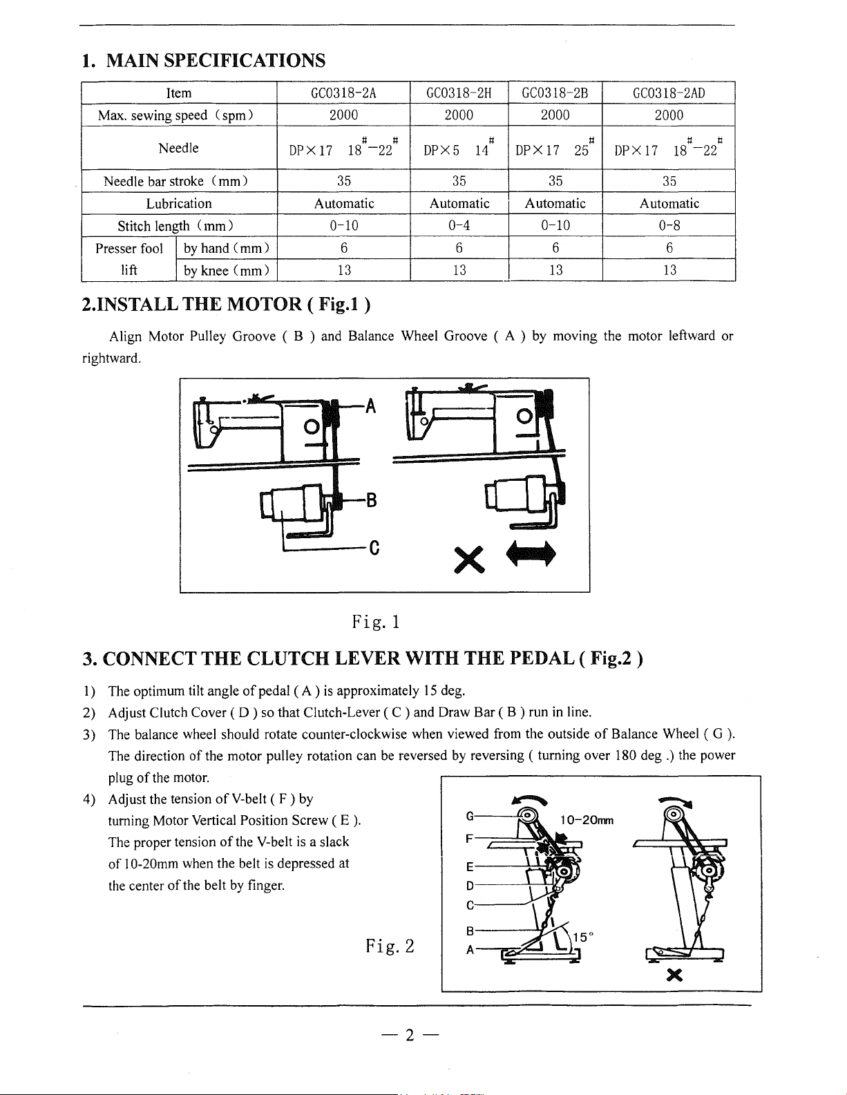
Align Motor Pulley Groove ( B ) and Balance Wheel Groove ( A ) by moving the motor leftward or
rightward.
Cspm)
Cmm)
mm)
by
hand Cmm) 6 6 6 6
by
knee Cmm)
THE
MOTOR
GC0318-2A GC0318-2H GC0318-2B
DPX
2000
t:l
18
17
35 35 35
0-10
13
t:l t:l
-22
2000
DPX5
0-4
13
14
DPX
( Fig.l )
5I
:=j_gft
2000
17
0-10
13
GC0318-2AD
2000
t:l t:l
DPX
25
17
35
0-8
13
18
-22
t:l
[[j
L-----C
x+-+
Fig. 1
3. CONNECT
1) The optimum tilt angle
2) Adjust Clutch Cover ( D ) so that Clutch-Lever ( C ) and Draw Bar ( B ) run in line.
3)
The balance wheel should rotate counter-clockwise when viewed from the outside
The direction
of
plug
4) Adjust the tension
turning Motor Vertical
The proper tension
of
the center
the motor.
1 0-20mm when the belt
THE
of
the motor pulley rotation can be reversed by reversing
of
the belt by finger.
CLUTCH
of
pedal
ofV-belt
of
(F)
Position Screw ( E
the V-belt
is
depressed at
LEVER
(A
) is approximately
by
).
is
a slack
WITH
15
de g.
THE
G
F
I
E
D
c
PEDAL ( Fig.2 )
(turning
of
Balance Wheel
over 180 deg
I
.)
the power
(G).
B
Fig.2
A
-2-
X
Page 5
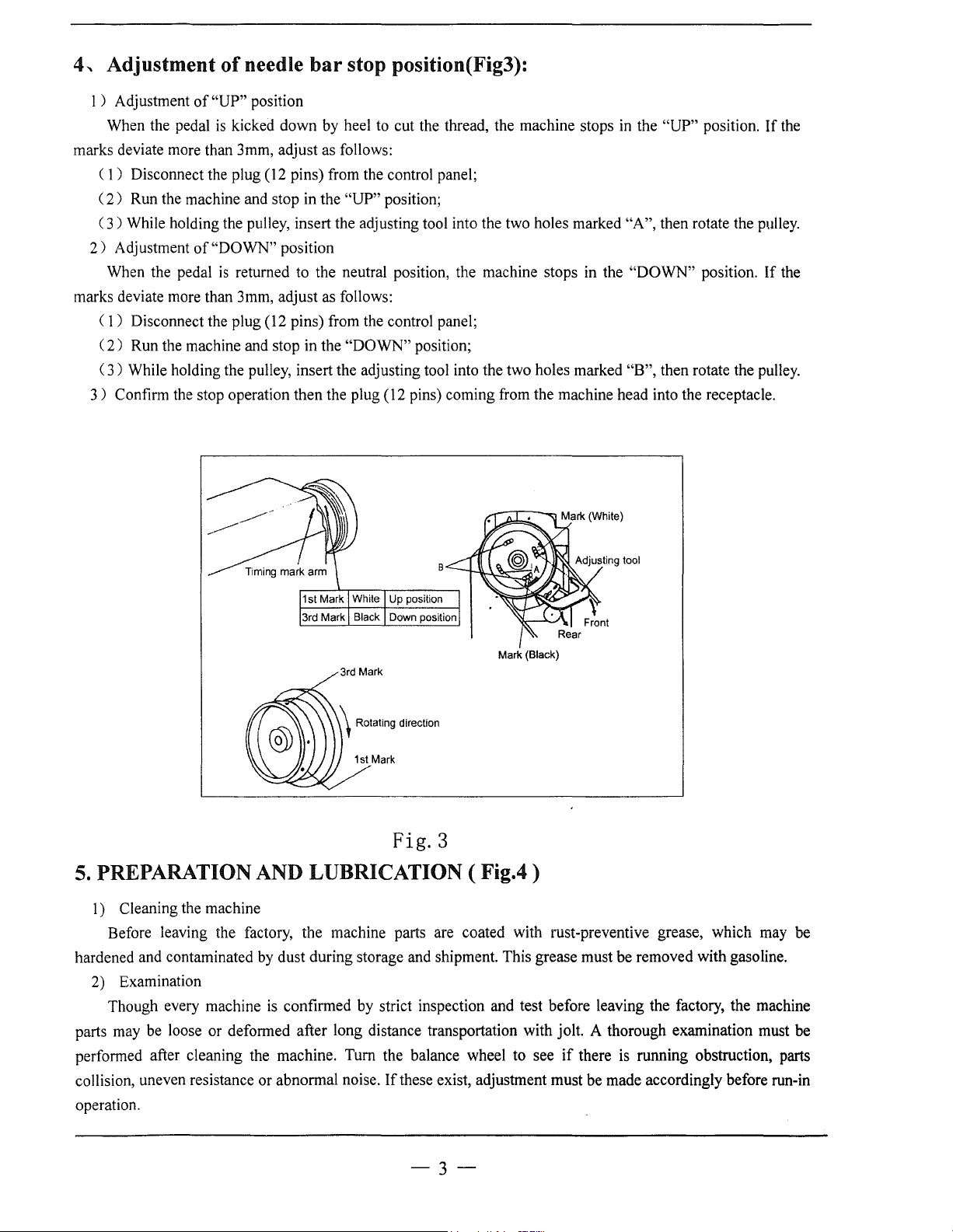
4-.
Adjustment
of
needle
bar
stop position(Fig3):
1 ) Adjustment
When the pedal
marks deviate more than 3mm, adjust as follows:
C
1)
Disconnect the plug (12 pins) from the control panel;
2)
Run the machine and stop in the "UP" position;
(
(
3)
While holding the pulley, insert the adjusting tool into the two holes marked "A", then rotate the pulley.
2)
Adjustment
When the pedal
marks deviate more than 3mm, adjust as follows:
(
1)
Disconnect the plug (12 pins) from the control panel;
2)
Run the machine and stop in the "DOWN" position;
(
(
3)
While holding the pulley, insert the adjusting tool into the two holes marked "B", then rotate the pulley.
3)
Confirm the stop operation then the plug (12 pins) coming from the machine head into the receptacle.
of
"UP" position
is
kicked down by heel to cut the thread, the machine stops
of
"DOWN" position
is
returned to the neutral position, the machine stops in the "DOWN" position.
in
the "UP" position.
If
If
the
the
Mark (Black)
3rd Mark
Fig.3
5.
PREPARATION AND LUBRICATION (
1)
Cleaning the machine
Before leaving the factory, the machine parts are coated with rust-preventive grease, which may be
hardened and contaminated by dust during storage and shipment. This grease must be removed with gasoline.
2)
Examination
is
Though every machine
parts may be loose or deformed after long distance transportation with jolt. A thorough examination must be
performed after cleaning the machine. Turn the balance wheel to see
collision, uneven resistance or abnormal noise.
operation.
confirmed by strict inspection and test before leaving the factory, the machine
If
these exist, adjustment must be made accordingly before run-in
Fig.4)
if
there
is
running obstruction, parts
-3-
Page 6
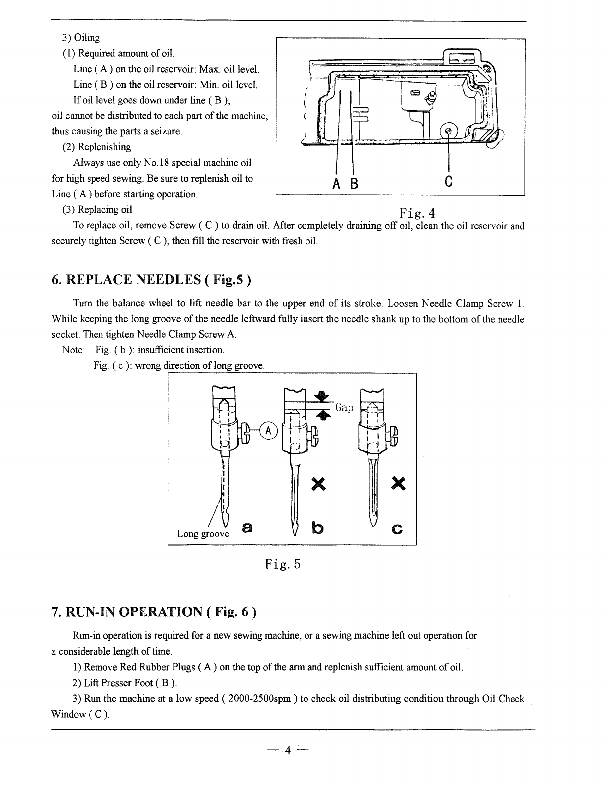
3) Oiling
(
1)
Required amount
Line (
A)
on the oil reservoir: Max. oil level.
Line ( B ) on the oil reservoir: Min. oil level.
Tf
oil level goes down under line ( B ),
oil cannot be distributed to each part
thus causing the parts a seizure.
(2) Replenishing
Always use only
for high speed sewing. Be sure to replenish oil to A 8 C
Line ( A ) before starting operation.
(3) Replacing oil
To
replace oil, remove Screw ( C ) to drain oil. After completely draining
securely tighten Screw
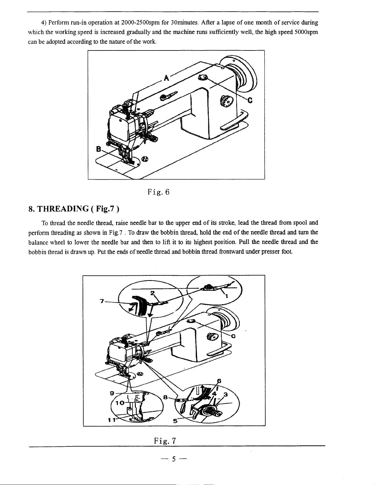
6.
REPLACE NEEDLES (
of
oil.
of
the machine,
No.l8
special machine oil
(C),
then fill the reservoir with fresh oil.
Fig.5)
I
I
Fig.
4
off
oil, clean the oil reservoir and
Turn the balance wheel to lift needle
While keeping the long groove
socket. Then tighten Needle Clamp Screw
Note: Fig. ( b
Fig.
):
insufficient insertion.
(c):
\\-Tong
of
the needle leftward fully insert the needle shank up to the bottom
direction
Long groove
oflong
bar
to the upper end
A.
groove.
Fig.5
of
its stroke. Loosen Needle Clamp Screw
of
the needle
1.
7.
RUN-IN OPERATION
Run-in operation is required for a new sewing machine, or a sewing machine left out operation for
::.
considerable length
1)
Remove Red Rubber Plugs (
2) Lift Presser Foot ( B
3) Run the machine at a
Window
(C).
of
time.
).
low
(Fig.
A)
speed ( 2000-2500spm) to check oil distributing condition through Oil Check
6)
on the top
of
the arm and replenish sufficient amount
-4-·
of
oil.
Page 7
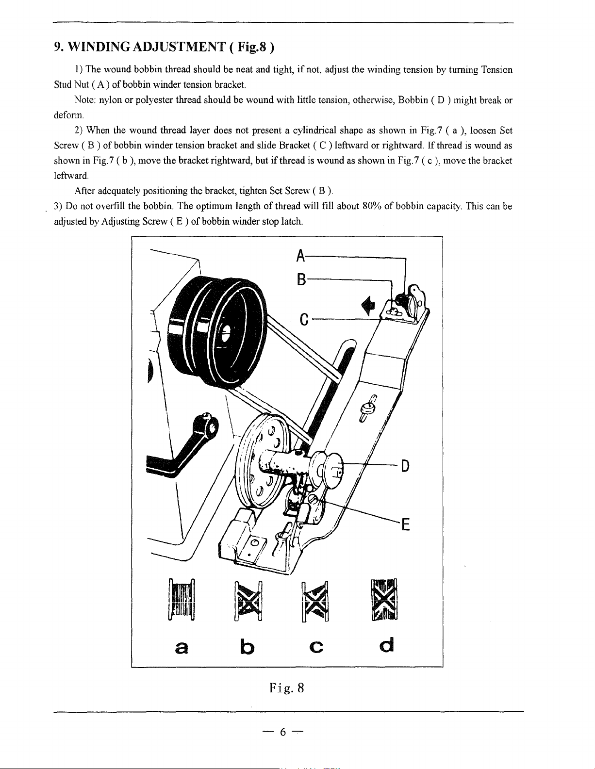
4) Perform run-in operation at 2000-2500spm for 30rninutes. After a lapse
which the working speed is increased gradually and the machine runs sufficiently well, the high speed 5000spm
can
be
adopted according
to
the nature
of
the
work
of
one month
of
service during
Fig.6
8.
THREADING
To
thread the needle thread, raise needle
perform threading as shown in Fig. 7 .
balance wheel
bobbin thread is drawn
to
( Fig. 7 )
lower the needle
up.
Put the ends
bar
bar
to
the upper end
To
draw the bobbin thread, hold the end
and then to lift
of
needle thread and bobbin thread frontward under presser
it
to its highest position. Pull the needle thread and the
of
its stroke, lead the thread from spool and
of
the needle thread and turn the
foot.
Fig. 7
-5-
Page 8
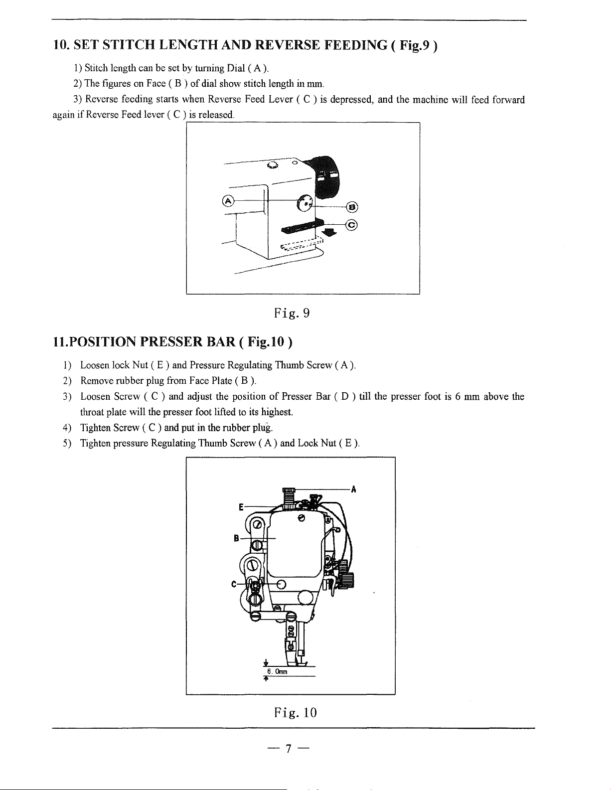
9.
WINDING ADJUSTMENT (
1)
The wound bobbin thread should be neat and tight,
(A)
of
Stud Nut
Note: nylon or polyester thread should be wound with little tension, otherwise, Bobbin ( D ) might break or
deform.
2)
When the wound thread layer does not present a cylindrical shape
Screw ( B )
shown in Fig.7
leftward.
After adequately positioning the bracket, tighten Set Screw ( B
3)
Do
not overfill the bobbin. The optimum length
adjusted by Adjusting Screw
bobbin winder tension bracket.
of
bobbin winder tension bracket and slide Bracket ( C ) leftward or rightward.
(b),
move the bracket rightward, but
(E)
of
bobbin winder stop latch.
Fig.8)
of
if
not, adjust the winding tension by turning Tension
as
if
thread is wound
thread will fill about 80%
as
shown in Fig.7
).
shown
in
Fig.7 (
(c),
of
bobbin capacity. This can be
a),
If
thread is wound
move the bracket
loosen Set
as
a
b
c
Fig.8
-6-.
d
Page 9
10.
SET STITCH LENGTH AND REVERSE FEEDING (
1)
again
Stitch length can be set by turning Dial
2)
The
figures
3)
Reverse feeding starts when Reverse Feed Lever ( C )
if
Reverse Feed lever
on
Face
(B)
of
dial show stitch length intmn.
(C)
is
released .
.---------------------------------~
(A).
is
depressed, and the machine will feed forward
Fig.9
Fig.9)
ll.POSITION
1)
Loosen lock Nut ( E ) and Pressure Regulating Thumb Screw ( A ) .
2)
Remove rubber plug from Face Plate
3) Loosen Screw ( C ) and adjust the position
throat plate will the presser foot lifted
4)
Tighten Screw
5)
Tighten pressure Regulating Thumb Screw
PRESSER BAR ( Fig.lO)
(B).
of
Presser Bar ( D ) till the presser foot is 6 mm above the
to
its highest.
(C)
and put in the rubber plug.
(A)
and Lock Nut ( E
).
Fig.
10
-7-
Page 10
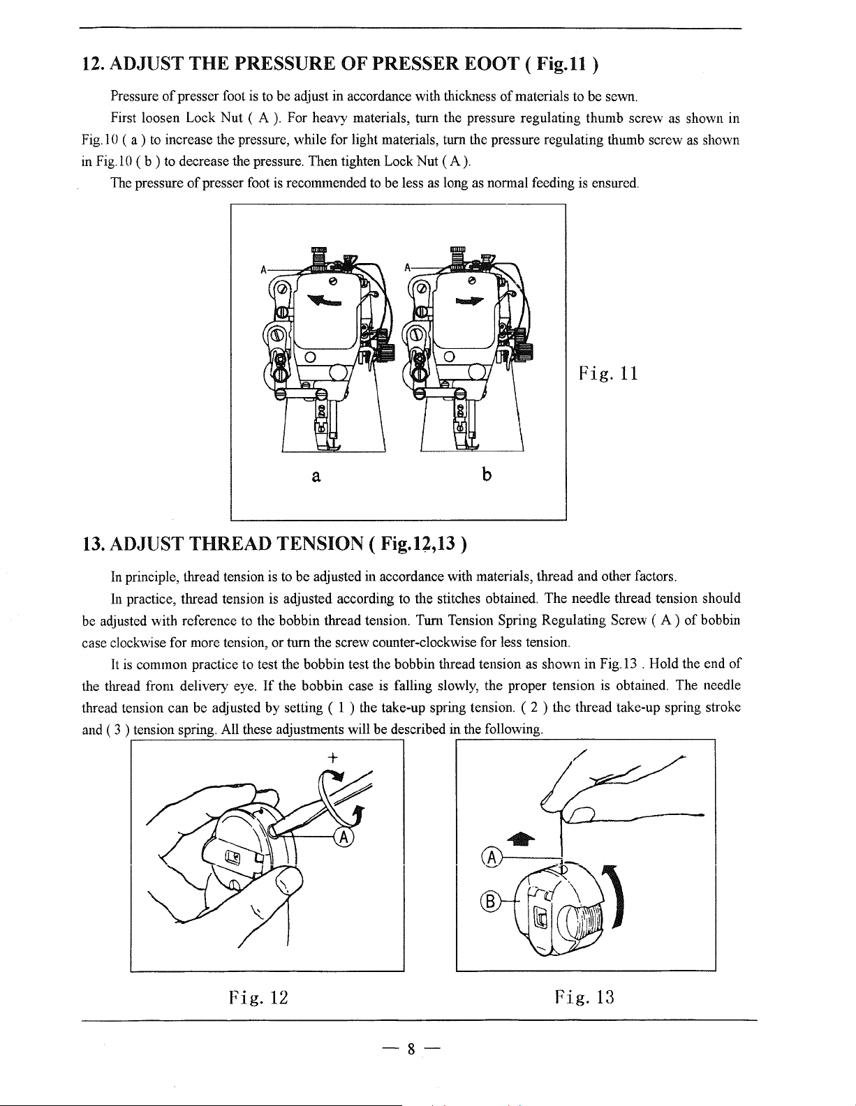
12.
ADJUST
THE
PRESSURE
OF
PRESSER EOOT ( Fig.11 )
Pressure
First loosen Lock Nut (
Fig.1 0
in Fig.l 0 ( b ) to decrease the pressure. Then tighten Lock Nut
The
(a)
to
pressure
of
presser foot is to be adjust in accordance with thickness
A).
For heavy materials, turn the pressure regulating thumb screw as shown in
increase the pressure, while for light materials, turn the pressure regulating thumb screw
of
presser foot is recommended to be less
as
a
of
materials to be sewn.
(A).
long as normal feeding is ensured.
Fig.
11
b
as
shown
13.
ADJUST THREAD TENSION ( Fig.1Z,13)
In
principle, thread tension is
In
practice, thread tension is adjusted according to the stitches obtained. The needle thread tension should
be adjusted with reference to the bobbin thread tension. Tum Tension Spring Regulating Screw (
case clockwise for more tension, or turn the screw counter-clockwise for less tension.
It
is
common practice to test the bobbin test the bobbin thread tension as shown in Fig.l3 . Hold the end
the thread from delivery eye.
thread tension can be adjusted by setting ( 1 ) the take-up spring tension. ( 2 ) the thread take-up spring stroke
and ( 3 ) tension spring. All these adjustments will be described in the following.
to
be adjusted in accordance with materials, thread and other factors.
A)
of
bobbin
If
the bobbin case is falling slowly, the proper tension is obtained. The needle
r-------~--------------------~
of
Fig.
12
--8--
Fig.
13
Page 11
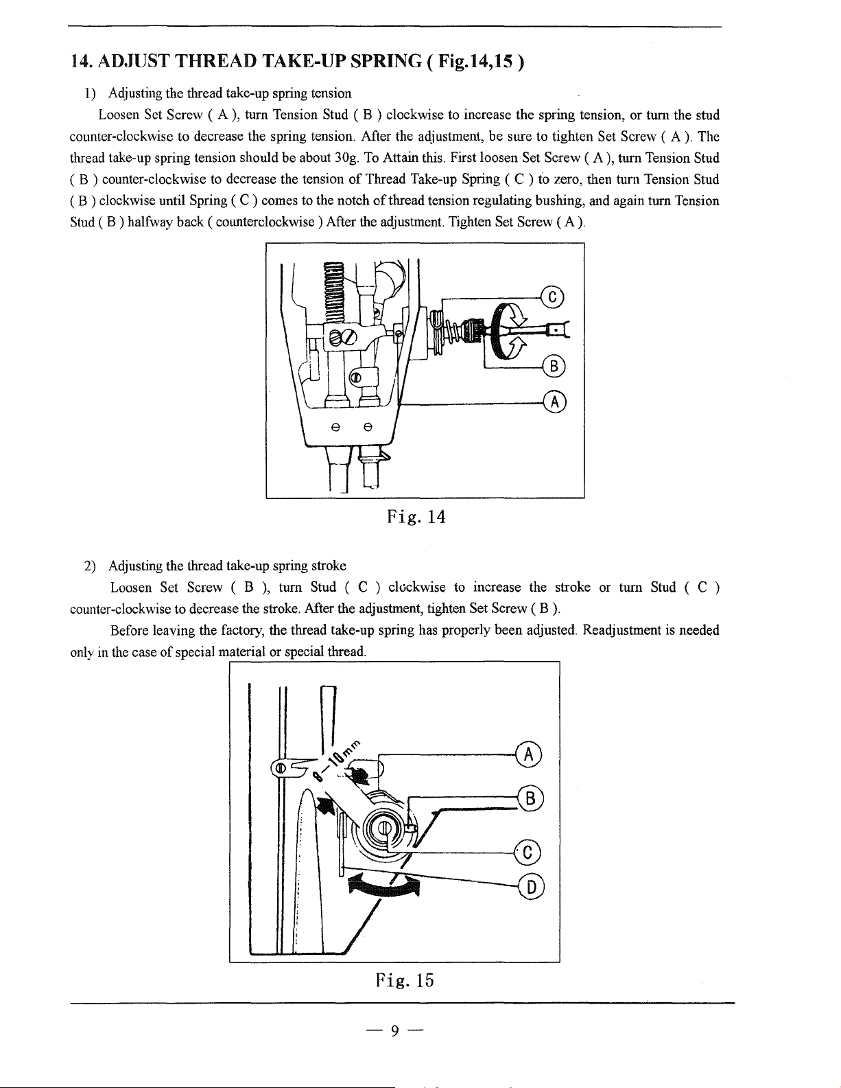
14.
ADJUST THREAD TAKE-UP SPRING (
1)
Adjusting the thread take-up spring tension
Loosen
counter-clockwise to decrease the spring tension. After the adjustment, be sure to tighten
thread take-up spring tension should be about 30g.
( B ) counter-clockwise to decrease the tension
(B)
clockwise until Spring
Stud ( B ) halfway back ( cmmterclockwise ) After the adjustment. Tighten Set Screw
Set Screw ( A ), turn Tension Stud ( B ) clockwise to increase the spring tension, or turn the stud
To
Attain this. First loosen Set Screw
of
Thread Take-up Spring ( C ) to zero, then turn Tension Stud
(C)
comes to the notch
of
thread tension regulating bushing, and again turn Tension
Fig.l4,15)
(A),
(A).
Set Screw (
turn Tension Stud
A).
The
Fig.
14
2)
Adjusting the thread take-up spring stroke
Loosen
counter-clockwise to decrease the stroke. After the adjustment, tighten
Before leaving the factory, the thread take-up spring has properly been adjusted. Readjustment
only
in the case
Set Screw ( B ), turn Stud ( C ) clockwise to increase the stroke or turn Stud ( C )
of
special material or special thread .
.-----~------------------------------.
Set Screw
,-----------(
(B).
A
is
needed
Fig.
15
-9-
Page 12
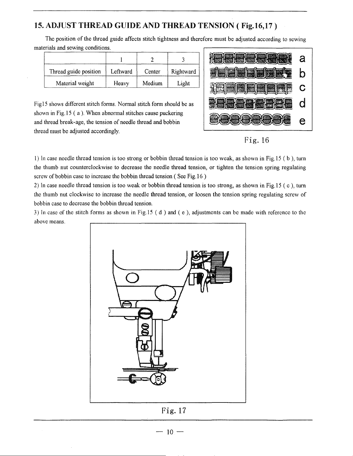
15.
ADJUST THREAD GUIDE AND THREAD TENSION ( Fig.16,17)
The position
materials and sewing conditions.
Thread guide position
Material weight Heavy
of
the thread guide affects stitch tightness and therefore must be adjusted according to sewing
1 2
Leftward
Center
Medimn Light
3
Rightward
a
b
c
Figl5 shows different stitch fonns. Normal stitch fonn should be
sho\\<n
in
Fig.l5 ( a
and thread break-age, the tension
thread must be adjusted accordingly.
l)
In
case needle thread tension is too strong or bobbin thread tension is too weak, as shown in Fig.l5 ( b ), tum
the thumb nut counterclockwise to decrease the needle thread tension, or tighten the tension spring regulating
screw of bobbin case
2)
In
case needle thread tension is too weak or bobbin thread tension is too strong,
the
thumb nut clockwise to increase the needle thread tension, or loosen the tension spring regulating screw
bobbin case
In
3)
above means.
to
case of the stitch forms
).
When abnormal stitches cause puckering
of
needle thread and bobbin
to
increase the bobbin thread tension ( See Fig.l6 )
decrease the bobbin thread tension.
as
shown in Fig.l5 ( d )
and
as
Fig.
16
as
shown in Fig.l5 ( c
( e
),
adjustments can be made with reference to the
),
d
e
tum
of
c
Fig.
17
-10-
Page 13
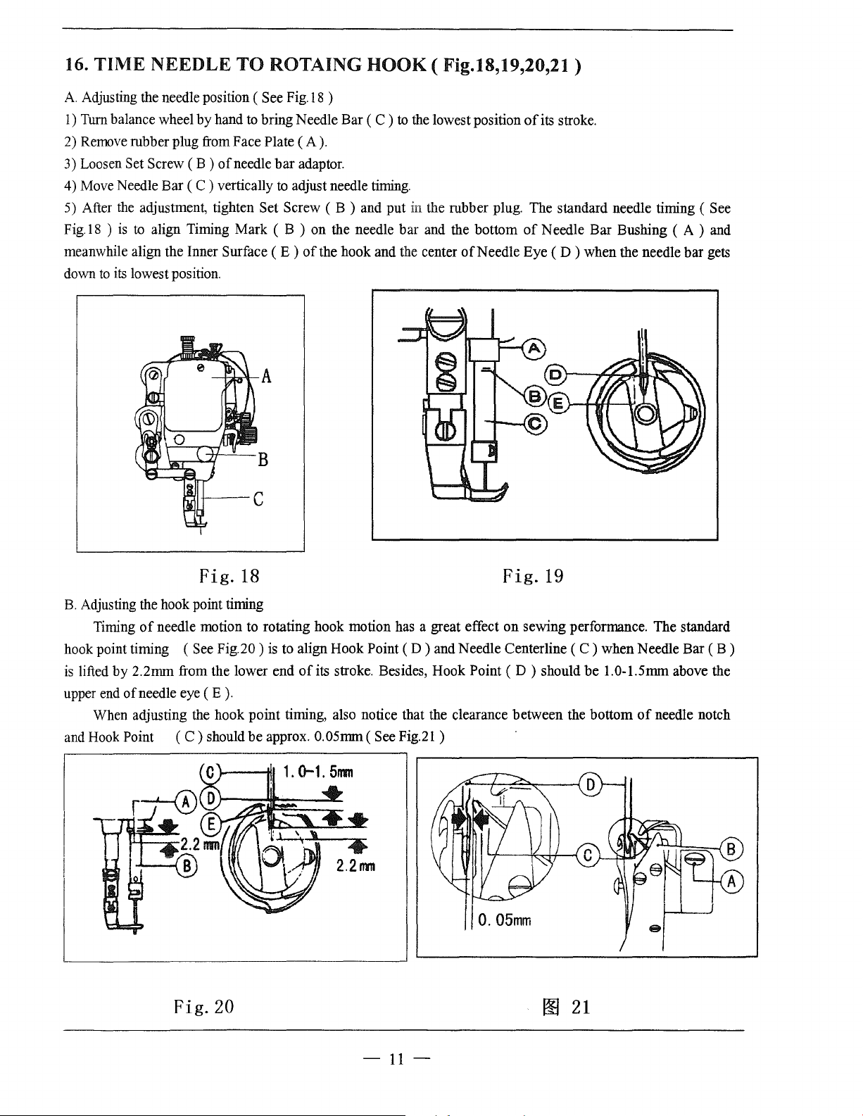
16.
TIME
A.
Adjusting the needle position ( See
Turn
I)
2)
Remove rubber plug from Face Plate
3) Loosen Set Screw
4) Move Needle Bar
5)
After
Fig.
IS ) is
meanwhile align the Inner Surface
down
to
NEEDLE
balance wheel by hand to bring Needle Bar ( C )
(B)
(C)
the
adjustment, tighten Set Screw ( B ) and put in the rubber plug. The standard needle timing ( See
to
align Timing Mark ( B ) on the needle bar and the bottom
its
lowest position.
TO
of
needle
vertically
ROTAING
Fig.
IS
)
(A).
bar
adaptor.
to
adjust needle
(E)
of
the hook and the center
HOOK
to
the lowest position
timing.
( Fig.18,19,20,21 )
of
its stroke.
of
Needle Bar Bushing ( A ) and
of
Needle Eye
(D)
when the needle bar gets
Fig.
18
B.
Adjusting the hook point timing
Timing
hook point timing
is
lifted by 2.2nnn from the lower end
upper
When adjusting the hook point timing, also notice that the clearance between the bottom
and Hook
of
needle motion to rotating hook motion has a great effect on sewing performance. The standard
(See
end
of
needle eye
Point ( C ) should
Fig.20)
(E).
is
to align Hook Point
of
its stroke. Besides, Hook Point
be
approx.
0.
(D)
and Needle Centerline
05nnn ( See Fig.21 )
Fig.
19
(D)
should be l.0-1.5nnn above the
(C)
when Needle Bar
of
needle notch
(B)
Fig.20
-
11-
00
21
Page 14
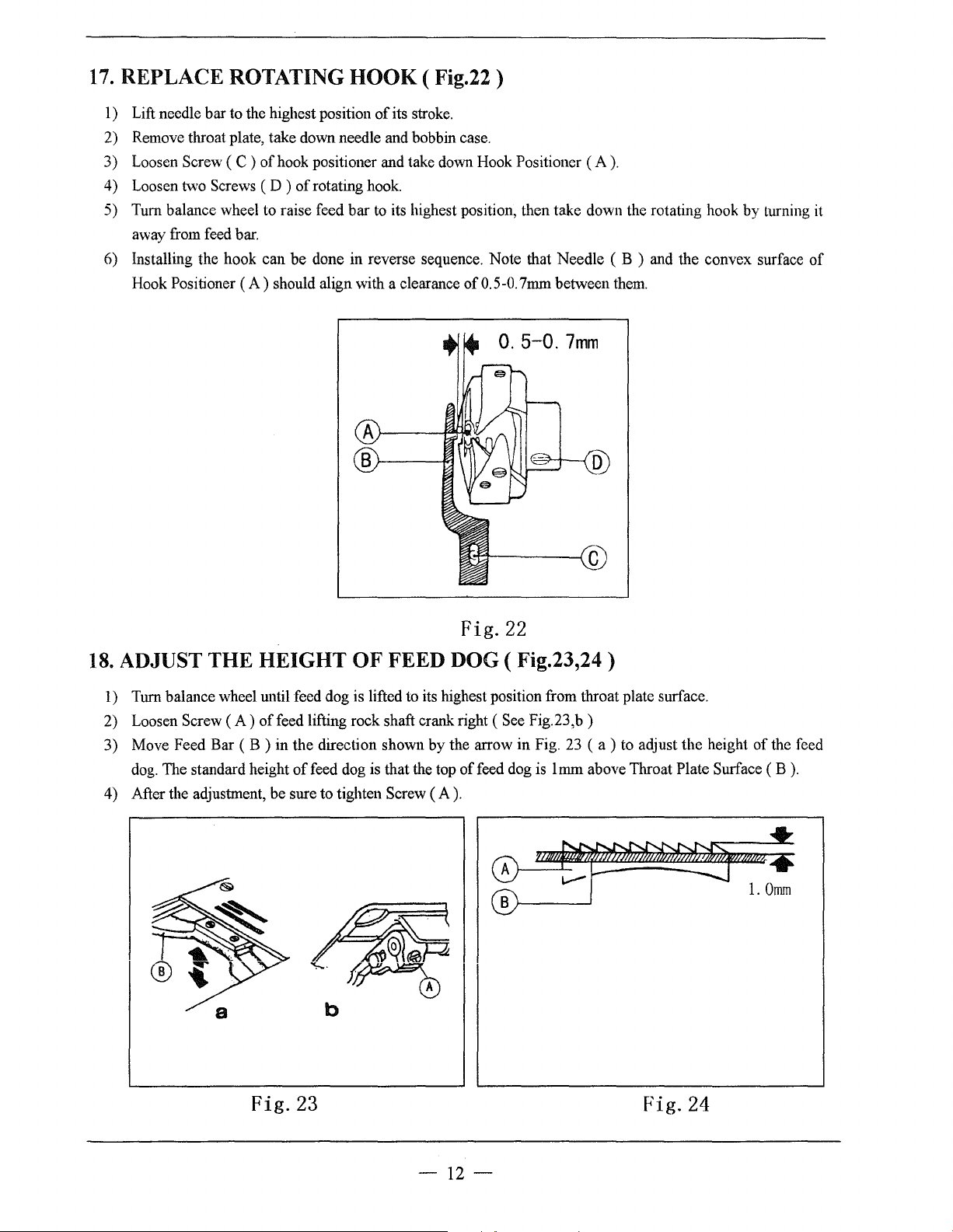
17.
REPLACE ROTATING
HOOK
( Fig.22)
1) Lift needle bar to the highest position
2) Remove throat plate, take down needle and bobbin case.
3) Loosen Screw ( C )
4) Loosen two Screws ( D )
5) Tum balance wheel to raise feed bar
away from feed bar.
6) Installing the hook can be done in reverse sequence. Note that Needle ( B ) and the convex surface
Hook Positioner
of
hook positioner and take down Hook Positioner
of
rotating hook
(A)
should align with a clearance of0.5-0.7mm between them.
of
its stroke.
(A
) .
to
its highest position, then take down the rotating hook by turning it
0.
5-0.
7mm
of
Fig.22
18.
ADJUST THE
1) Tum balance wheel until feed dog is lifted to its highest position from throat plate surface.
2)
Loosen Screw
3) Move Feed Bar ( B ) in the direction shown by the arrow in Fig.
dog.
The standard height
4) After the adjustment, be sure to tighten Screw
HEIGHT
(A)
offeed lifting rock shaft crank right
of
OF
FEED DOG ( Fig.23,24)
feed dog is that the top
(A).
(See
of
feed dog is
Fig.23,b)
23
lmm
( a )
to
adjust the height
above Throat Plate Surface ( B
of
the feed
).
Fig.23
-12-
Fig.24
Page 15

19.
Adjustment of feed dog inclination (Fig.25,26):
If necessary, adjust the inclination according to the material to be sewn
Eccentric
I) Loosen the screw "A".
2) Rotate the eccentric shaft clockwise or cmmterclockwise with screw driver.
3) Tighten the screw
Position of mark on the
eccentric shaft
"A".
~-
shaft
Horizontal
Feed dog
~
Standard
as
follows:
Fig.
25
8)'
8).
20.
TIME FEED MOTION
The standard timing
Plate Surface
(B)
when the point
of
Up
Down
~
~
Front up
Front
(MAX.)
down
(MAX.)
Fig.26
TO
NEEDLE
feed motion to needle motion is that the top
of
Needle
(A)
reaches Throat Plate Surface
MOTION
( Fig.27,28,29)
of
feed Dog ( C ) is flush with Throat
(B).
See Fig.27.
Fig.27 Fig.28
-13-
Page 16

If
feed motion
1)
Remove Ann Side Cover .
2) Loosen Set Screws
3) Hold Feed and Feed Lifting Eccentric ( B ) and turn Balance Wheel ( E ) slowly until the upper edge
Arm Shaft Oil Hole ( C ) aligns with the lower edge
eccentric.
is
not timed to needle motion, adjust
(A)
and ( D )
of
feed and feed lifting eccentric.
as
follows
(See
Figs.28 and 29
of
Reference Hole ( G )
).
of
feed and feed lifting
Fig.29
of
21.
ADJUST OPENING
within the presser foot lift range
1)
Remove the rubber plug from the back
2) Move the tension releasing cam leftward for earlier opening or rightward for later opening. It will facilitate
the adjustment to put under the presser foot a block
3) After the adjustment, fully tighten Screw
TIME
of
OF
2-7mm opening time
of
arm and loosen Screw
(A).
THE TENSION DISCS ( Fig.30)
of
the tension discs can be adjusted as follows:
(A)
of
knee lifter lever ( left
as
thick as the presser foot lift.
).
Fig.30
-14-
Page 17

22.
LUBRICATION ADJUSTMENT ( Fig.31 )
A Adjusting oil pump.
ordinary operation, adjustment is not required for the oil pump.
In
check window when the machine runs at a low, speed ( approx.2000spm ), reduce the clearance
hole.
B.
Adjusting the lubrication
The lubrication
1) Turn
counterclockwise to decrease oil.
2)
Oil Adjusting Screw (
tightened, oil amount is maximun1.
3) Readjustment depends on temperature,
as
follows: remove the throat plate and place a piece
then check the oil splashed on the paper.
of
the rotating hook can be adjusted by Oil Adjusting Screw
Oil Adjusting Screw ( A ) clockwise to increase oil and
of
rotating
A)
adjusts oil amount within 5 turns.
hook
sev.ring speed and the like. In practice, oil amount
of
paper on instead,
If
oil splashing does
(A)
turn
Oil Adjusting Screw ( A )
When
Oil Adjusting Screw (
run
the machine for about 20 seconds,
not
as follows:
A
occur in the oil
of
the by-pass
A)
is fully
can
be judged
Fig.31
-15-
~
•
(--)
"--"
Page 18

23. REGULAR CLEANING ( Fig.32,33,34)
1) Cleaning feed dog
Remove the throat plate and clear
Feed
(See
dog
Fig.32)
off
the dust and lint between feed dog tooth slots.
Feed
Fig.32
2) Cleaning rotating hook
Swing out the machine head and clean the hook. Wipe the bobbin case with soft cloth.
(See
Fig 33 )
Fig.33
Hook
bar
Clem1ing
3)
s,ving
oil pump, screen
out
t..l-te
machine
(See
head
and
Fig.34)
clear
off
the
dust
and
di.rt
Screen
on
oil
pump
screen.
Fig.33
-16-
Page 19

24, Adjustment of thread
1)
TI1e
thread trimmer mechanism illustrated as Fig.35.
trimmer
mechanism:
~----;-]
L~~·_::?
blade
----
bracket
~
'"'"'
""'
F1xed
blade
uni~.J
--
"L
~
Tw1st
spnng
/
Movable knife
C 1 ) Operation stroke
a.
b.
This stroke can be adjusted
2)
Adjustment
C 1 ) Position
See the Fig.36, the standard distances from the needle center
are 7.5mm and 5mm from the movable knife (left) and fixed
blade respectively.
( 2 ) Adjustment
With the solenoid activated, turn on the machine. This rotates
the threadtrimming cam which rotates the movable knife (left).
When the movable knife (left)has moved to its farthest distance,
the standard engagement
engagement can
C 3 ) Adjustment
a.
If
a thread is poorly cut, particularly when
slightly increase the engaging pressure. This should solve the
problem.
b.
The engaging pressure can be adjusted in this way:
tiett)
of
Standard operation stroke is 6.0mm.
of
knife engagement (Fig.36):
of
movable knife (left) and fixed blade:
of
knife engagement:
of
the blade is 1.5mm-2.0mm. The
be
adjustedby properly mounting the drive arm.
of
knife engagement pressure:
Knife driving /
shaft
Cam
crank(l)
the thread trilmner solenoid:
by
usmg nut "A".
follower
it
1 , Stopper
Cam
follower Drive lever Stopper plate
crank (2)
is thick,
Knife driving
Movable
Tw1st spring
I.
5-2
knife (left)
Smm
/®
crank
.Omm
Fixed
Fixed
blade
®
blade
Loosen lock nut
and adjust it
by
using adjustmg screw
"A"
"B"
-17-
Movable
Fixed
Fig.36
knife
blade
(left)
Page 20

A.
ARM BED AND ITS ACCESSORIES
5
1
6
41
42
43
36--6
11----44
33
29
28
23
31
27
26 25
32
24
-18-
Page 21

A.ARM BED AND ITS ACCESSORIES
Fig.
No.
AOI
AOI
AOl
A02
A02
A02
A02
A03
A04
A05
A06
A07
A08
A09
AlO
All
Al2
Al3
Al4
Al5
Al6
Al7
Al8
Al9
A20
A21
A22
A23
A24
A25
A26
A27
A28
A29
A30
A31 I HA115B0709
A32
A33
A34
A35
A36
A37
A38
Part No.
HM307B8001
HN208B8001
HN606B8001
HM309B8001
HN408B8001
HN305B8001
HN608B8001
H924025050
H005008060
H2005B0065
HA306B0674
HA607B0671
HA106B0676
HA700B2030
HA300B2170
H6028B8001
H6029B8001
Hl210B0671
H6030B8001
HA112B0691
HA112B0692
HA112B0693
HA112B0694
H007013030
HA112B0695
HA100B2100
HA100B2110
HA115B0701
HA310B0701
HA505B0671
HA310B0702
HA310B0705
HA505B0672
HA310B0703
HA115B0708
HA115B7010
HA115B7011
HA300B2080
HA600B2050
HA300B2090
HA300B2100
HA300B2110
Description
Arm
Arm
Arm
Trade
mark
plate
Trade
mark
plate
Trade
mark
plate
Trade
mark
plate
rivet
Spring washer
Face
plate
Rubber plug (
Thread guide
Thread guide screw
Face
plate
Screw group
Arm
side
Gasket
Check
window
Rubber plug (
Screw type
Spring
Disc
for
Spacer
Stop
ring
Pre-tension
Three-hple
Set
screw
Thread
Oil
thumb
Thread
Thread
Thread
Thread
!Thread
lset
screw
~~hrea~.tension
;:,cop
GlSC
Rubber
Set
screw
Thread guide
Rubber plug (
Rubber plug (
Red
rubber plug (
<P
on
screw
cover
for
arm
<P
tension
for
pre-tension
pre-tension
for
pre-tension
thread
thread
tension
nut
tension
tension
tension
take-up
tension
ring
at
<P
<P
11.
8 )
face
plate
side
cover
22
)
stud
guide
guide
stud
spring
releasing
disc
spring
regulating
releasing
arm
center
8.
8 )
27
)
<P
5.
7 )
disc
bushing
pin
::r:
<
N N N
I I I
00 00
M
- -
0 0 0
u
·U
C) C)
1
1
6 6
2 2
1
3 3 3
1
1 1
2 2 2
4 4
1 1
1
1
1
1
1 1
2
1
1 1
1 1
1
1 1
1 1 1
1 1 1 1
1
1 1
2 2
1 1
1 I 1
I
1
I
I
1
I
I
1
1
1
1
2 2
1 1
2 2
~
00
M
M
-
u
C)
1
1
1
1
1
1
1
1
2
1 1 1
1 1 1
1
1
I
1
I
1
1 1 1
1
1
Q
N
I
00
M
-
0
u
C)
1
1
1
1
6 6
2 2
1 1
1 1
1 1
4 4
1 1
1 1
1
1 1
1 1 SMll/64(40) X
1 1
2 2
1 1
1 1
1 1
1 1
1 1
2
1
1 I
1
I
1
I
1
1 1
1 1
2
1 1
2 2
GB/T827
GB/T93
3
SM9/64
SM11/64
2
1
GB/T896
SM11/64
SM1/4(40) X 17
1
2
1
I
1
1
ISM9/64
1
1
SM15/64(28)
2.
Remarks
<P
2.
6
(40)
X 6
(40) X 20
3
(40) X 5.
(40) X 4
5 X 5
16
5
I
I
X6. 8
-19-
Page 22

A.ARM
Fig.
No.
A39
A39
A39
A40
A41
A42
A43
A44
A45
A46
A47
A48
A49
A50
A51
A52
A53
A54
A
HA124B0712
HA124B0713
HA100B2220
HA300B2140
HA300B2130
HA307B0673
HA300B2160
H6409B8001
H6410B8001
HA710B0671
HA710B0672
HA112B0692
HA710B0673
55
HA710B0674
Part No.
H2100B2120
HN208B8001
H6520B8001
HA300B2190
HA124B0711
BED
AND ITS ACCESSORIES
Description
Needle
Needle
Needle
Needle
Slide
Slide
Screw
Leg
Plate
Screw
Rubber plug
Screw
Arm
Gasket
Nut
Spring
Disc
Screw
Pre-tension
plate
plate
plate
plate
plate
plate
for
guide
bed cover
for
arm
for
pre-tension
for
pre-tension
screw
spring
bed cover
thread guide
~
::r::
co
N
N
I I I
00 00
......
(")
0 0 0
u u u
0 0 0
......
(")
N
00
......
(")
1
1
2 2
1
1
1 1
2 2
3
3
1 1
2 2
1
1
5 5
1 1
1 1
~
N
00
......
(")
0
u
0
1
2 2
1 1
1 1
2 2
3 3
1 1
2 2
1 1
5
1
1
I
1
1
1
2
1
1
SM11/64
SM3/32
SM11/64
Remarks
(40) X 4.
(56) X 2.
(40)
X 5
5
2
-20-
Page 23

B.
NEEDLE BAR
AND
3 1
TAKE-UP LEVER,. ARM SHAFT MECHANISM
13 10
72~
73
__::r
74
75
76
-21-
Page 24

B.NEEDLE BAR AND TAKE-UP LEVER-. ARM SHAFT MECHANISM
<c:
::I::
o::l
Fig.
No.
801
801
802
802
803
804
804
805
806
807
BOB
809
810
811
812
813
814
815
816
817
818
819
819
820
821
821
821
822
823
823
824
825
826
827
828
829
830
831
B32
B03
B34
835
836
Part
No.
H11111C204
HA3111C104
H11112C104
HA304C0012
HA104C0653
HA504C0651
HA104C0655
HA104C0656
HA304C0653
HA104C0658
HA104C0659
HA100C2020
HA307C0661
HA307C0662
HA100C2060
HA100C2070
HA100C2080
HA100C2100
HA300C2050
HA804B0652
HA500C2060
H2100C2010
HA700G2030
HA500C2030
H2000G2030
HA700G2040
H6524B8001
HA100C2170
HA100C2180
HA704G0065
HA100C2190
HA100C2200
H2604C0651
HA104D0652
HA108G0661
HA105D0662
HA100D2030
HA100D2040
HA100C2020
HA300D2020
HA306D0066
H2000C2040
HA110D0672
Description
Therad take-up
Therad take-up
Thread take-up
Thread take-up
lever
lever
lever
lever
link
link
Hinge pin
Thread take-up crank
Needle bearing
Set screw (
Needle
Needle
bar
bar
link
adaptor
left-handed
)
Screw
Set screw
Needle bar crank
Set screw
Set screw
Set screw
Needle
Felt
Red
bar
plug
rubber plug (
bushing
( upper )
<P
8.
8 )
Needle bar bushing ( lower )
Thread guide
Needle
bar
for
needle
bar
Needle bar
Thread guide
for
needle
bar
Needle
Needle
Needle
Needle
Guide
Guide
Set
Slide
Arm
Rubber plug
Collar
Set
Arm
Arln
Set
Arvn
Oil
clamp
for
for
screw
block
shaft
for
screw
shaft
shaft
screw
shaft
seal
screw
slide
block
slide
block complete
<!>7.
4X
(
10
bushing(left)
bushing(middle)
bushing(right)
)
Balance wheel
Set
screw
bushing
C'J
C'J C'J
I I
00 00
,....,
,....,
M M M
0 0
u
u
c.!l c.!l
1
1
1
1
1 1
1
1 1
2
2
1
1
1
1
1
1
1
1 1
1
1
1
1
2
2 2
1
1
1
1
1
1
1
1 1
1
1 1
1
1 1
1
1 1
1
1
1
1 1
1
1
1
1 1
1
1 1
2
2 2
1
1 1
1
1 1
2
2 2
1
1 1 1
2
2
1
1
1
1
1
1
1
1
1
1
1
1 1
2
2
I
00
,....,
0
u
c.!l
1 1
1 1
1 1
2 2
1 1
1 1
1 1
1
1
1
1
1
1
1
2
1
1
1
1
1
2
~
C'J
I
00
,....,
M
0
u
c.!l
1
SM9/64
1
SM9/64
SM15/64(28) X 10
1
1
2
SM1/4(40)
SM9/32
1
SM9/32/
1
1
1
1
1
1
1
1
DPX
1
17
DPX5
DPX
17
SM1/8
1
1
SM11/64
2
1
1
2
C'U1
I
Uli.U/
At
'-!"\'"tV}
2
1
1
SM15/64
1
1
1
1
2
SM15/64(28) X 12
Remarks
(40)
X 7
(40)
X 6
X6
(28) X 13
(28) X 14
22t:i
14t:l
25t:l
(44) X 4.
(40)
An\
v A
A "t
(28) X 10
5
X 8
-22-
Page 25

B.NEEDLE BAR AND TAKE-UP
Fig.
I
I
Part
No.
B37
B38
B38
B39
840
840
B41
B42
843
B44
B45
B46
B47
B48
849
B50
851
B52
B53
854
855
B56
857
B58
B59
860
86I
B62
B63
B64
865
866
867
868
869
I
870
871 I HA704B06531Hook
872
B72
B73
87 4 HA608E0067
87 4 HA300E2070
87 4 HA900E2030
No.
HA100D2080
H6510D8001
HA7311C106
HA100C2020
H6511D8001
HA7311C206
HA7311C306
HA112D3013
HA7311C506
HA112D3012
HA113D2112
HA113D2122
HA108C0663
HA113D2212
HA113D2222
HA100D2110
HA600D2010
HA100C2020
H2100D2010
HA1111E104
HA1111E204
HA305E0661
HA305E0662
HA106E0071
HA100E2040
HA100E2050
HAIOOE2060
HA311E0671
HA110E0672
HA300E2100
HA300E2110
HA600E2020
HA104F0654
HA604E0651
HA710E0691
710£0692
HA
H2100E2010
HA300E2050
HA100E2150
Screw
Feed and feed
Feed and feed
Set screw
Feed
Feed
Set
Crank rod
Feed rock
stop
Bevel gear
Bevel gear
Set screw
Bevel gear
Bevel gear
Vertical
Vertical
Set
Vertical
Filter
Filter
Collar
Set screw
Oil
Hook
Oil
Spring
Hook
Oil pipe
Plunger
Plunger
Guide
Screw
Hook
cam
Screw
Rotating
Rotating
Screw
Bobbin case
Bobbin case
Bobbin case
cam
cover
cam
cover
screw
for
ring
for
for
for
for
shaft
shaft
screw
shaft
screw
for
hook
seal
for
shaft
bushing (
adjusting
for
oil
shaft
bushing (
for
spring
plate
shaft
shaft
bushing
hook
hook
Description
lifting
lifting
feed
lifting
arm
shaft
vertical
hook
shaft
vertical
bushing(
bushing(
shaft
rotating
left
screw
adjuster
right
hook
shaft
positioner
positioner
eccentric
eccentric
shaft(upper)
shaft(lower)
upper )
lower )
hook
bushing
LEVER,
rock
shaft
shaft
)
)
ARM SHAFT MECHANISM
<c:
::r::
l:l:l
I
00
......
c.!l
1
1
2
1
3
1
1
1
1
1
1
1
1
1
1
1 1
1
1 1
1 1
1 1
1 1
I
I
~
C\1
I
00
......
C'?
0
u
c.!l
SM11/32
1
1
SM15/54(28) X7
2
1
82T2-003C1a1
3
1
1
1
1
SM1/4(40) X7
8
1
1
1
1
SM15/64
2
1
SM3/16
1
1
SM15/64
1
1
SM11/64
1
1
SM15/64
I
1
I
2
SM11/64
Remarks
(28) X 10
(28) X 10
(32)
(28) X 4.
(40) X 28.
(28) X 10
(40) X 13
I
I
C\1
I
00
......
C'?
0
u
c.!l
1
1
2
1
3
1
1
1
1
1
8
1
1
1
1
2
1
1
1
1
2
1
1
I
1
1
1
1
1
1
1
1
C\1 C\1
I
00
......
C'? C'?
0 0
u u
c.!l
1
1
2
1
3
1
1
1 1 1
1 1
1 1
8 8
1
1
1
1 1
2 2
1 1
1 1 1
1
1
2 2 2
1
1
I
1
1
1
1
1 1 1
1 1 1
1
1
I
I
I
I
X 9
5
5
I
-23-
Page 26

B.NEEDLE BAR AND TAKE-UP LEVER-. ARM SHAFT MECHANISM
(:Q
::c:
Fig.
No.
B75
B75
B75
B76
B76
B76
B76
Part
No.
H1100E2010
HA100E2170
HA900E2030
H1105E0066
HA500E2030
H6519B8001
HA906E0066
Bobbin
Bobbin
Bobbin
Rotating
Rotating
Rotating
Rotating
Description
hook
complete
hook complete
hook complete
hook
complete
<
N N N
00
("')
-
0 0 0
u u u
c.:> c.:> c.:>
I
I
00
("')
-
1 1
1
1
1
00
("')
-
1
~
I
N
I
00
("')
-
0
u
c.:>
1
1
Remarks
-24-
Page 27

C. STITCH REGULATOR MECHANISM
2
1""
5
13
11
lrf:t
12
53
22~---
6
2
27
~-
&-..
23~
/ •
<~--
28
~. ~
......
" ,",.
\ j
29
.. ---··
\
30
•
24
23
221
..
·
!.
_...
•
·:.6----
\a
31
..
~'t;:i,=--.
...
---··
:•
25
32
33
-25-
Page 28

C.STITCH REGULATOR MECHANISM
Fig.
No.
COl
C02
C03
C04
C05
C06
C07
COB
C09
ClO
Cll
Cl2
Cl3
Cl4
Cl5
Cl6
Cl7
Cl8
Cl9
C20
C21
C22
C23
C24
C25
C26
C27
C28
C29
C30
C31
C32
C33
C34
C34
C35
C36
C37
C38
C39
C40
C41
C42
Part
No.
HA700C2060
HA7311C406
HA111G0683
HB5251F081
HA113F0684
HA100C2190
HA704B0655
HA100C2020
HA100F2040
HA700B2120
H2600E2050
HA800F2010
H2605E0661
H2207D0671
HA104F0654
HA100F2130
HA113F3021
HA113F3022
HA100F2110
HA309F0671
HA113F0683
HA706Cll91
HA8211C305
HA706Cl1Bl
HA7311C806
HA7311CF06
HA700C2050
HA111G0683
HA7311CC06
HA7311CD06
HA7311CG06
HA7311CE06
HA700C2040
HM308F8001
HB5253F081
HA720F0686
HA7421F120
HA100F2080
HA100F2090
HA720F0681
HA109F0674
HA720F0683
HA720F0685
Description
Pin
Connecting rod
stud
Screw
Feed
regulator
Screw
Screw
Bushing
for
feed
Screw
Pin
Robber plug
Spring
Bracket
spring
Reverse feed crank
Slide
block
pin
Screw
Screw
Reverse feed
lever
0-ring
Washer
Reverse feed
Screw
link
(short)
lever
Link (long)
Link
stud
Screw
Link
stud
Feed
regulator
shaft
Screw
Screw
Screw
Stitch
Link
Feed
Plate
Plate
length
stud
regulator
for
stitch
for
stitch
adjusting
shaft
Screw
Dial
Stopper
Spring
Screw
for
bar
pin
stopper
0-ring
Stopper
pin
releasing
Bushing
regulator
shaft
(left)
crank
(right)
length
length
pin
lever
~
N N
I
00
M M
- -
0 0
u
CJ
1 1
co
~
N
I
00
00
M
-
0
u
u
CJ CJ
1 1
I
.2
1 1
1 1
1 1 1
1 1
1 1
1 1
1 1
2 2 2 2
1
1 1 1
1
1 1 1
1 1 1 1
1 1
1 1
1 1 1 1
1 1 1 1
2 2 2
2
2 2 2
1 1
1 1
1
1
1 1 1
1
1
1 1
2
2 2
1
1
1 1
1 1
1 1
1 1
1 1
1 1
1 1
1 1
1
1 1
1 1 1
1
1 1
1 1 1 1
1 1 1 1
1 1 1
1
1 1 1
1
1
1
1
~
N
I
00
M
-
0
u
CJ
1
1
1
1
1
1
1
1
1
2
1
1
1
2
1
1
1
1
Remarks
-26-
Page 29

C.STITCH REGULATOR MECHANISM
Fig.
No.
C43
C44
C45
C46
C47
C48
C49
C50
C51
C52
C53
C54
C55
C56
C57
C57
C58
C59
C60
C6l
C62
C63
C64
Part No.
HA720F0687
HB5255F081
H2204D0652
H007013040
H2204D0653
HA806C0674
HA806C0675
HA800F2020
50
HA1511F115
HA1511F215
HA300F2050
H1204E0652
HA100C2190
H1404E0651
H1204E0651
HA104F0654
HA115F0692
HA100F2140
HA109F0673
HA115F0691
Hl205E0661
HA109F0671
Coil
spring
Reverse
Pin
Stop
Spring
Spring
Spring
Screw
Stop
shaft
Slide
Rubber piug
Stitch
Screw
Feed
Feed
Screw
Spring
Spring
Screw
Crank
Dial
Screw
link
ring
retainer
retainer
ring
block
length
regulator
regulator
holder
bar
Description
adjusting
swing
shaft
::r:
I I
00
M M
-
0 0
u
1
1
1
1 1
l l
1
1
1
c:o
N
00
-
u
C)
1
1
1
~
N N
I
00
M
-
0
u
C) C)
1 1 1
1 1 1
1 1 1
1 1
1 1 1
1 1 1
1 1
1
1
l
1 l
~
N
I
00
M
-
0
u
C)
1
1
1
1
1
1
1
Remarks
I
I
-27-
I
I
I
Page 30

D.
FEEDING AND FEED LIFTING MECHANISM
21
35
36
-28-
Page 31

D.
FEEDING
AND
FEED LIFTING MECHANISM
Fig.
No.
DOl
002
003
004
004
004
005
006
007
008
009
010
011
012
013
014
015
016
017
018
019
020
021
022
023
024
025
026
027
028
029
030
031
032
033
034
035
036
Part
No.
HA104G00ll
HA304G0656
H6507G710l
HA104G0653
H2900G2010
H652lB800l
HA104G0654
HA705J0654
HA300C2030
HA104G0656
H6505G800l
H6504G8001
HA104G0012
H6505G8001
HA8211C205
HA8311CB03
HA8211C205
HA8311C803
HA105D0662
HA108G0661
H2100G2020
HA305E0662
H007009150
H2100G2010
HA304G0655
HA305G0664
HA100G2130
HA108G0661
HA704K0652
HA100G2120
HA100C2020
H007009150
HA105D0662
HA111G0683
HA306G0671
HA100G2070
I
I
HA104G0012
H1204D0651
Feed rock
Screw
Feed
bar
Feed
dog
Feed
dog
dog
Feed
Screw
Hinge
pin
Screw
Washer
Hinge
pin
Feed rock
Screw
Screw.
Feed rock
Link
stud
Screw
Screw
Set screw
Collar
Bushing
Set screw
C-type
Feed rock
Oil
braid
Oil
braid
Washer
Collar
Feed
lifting
Bushing
Set screw
C-type
Screw
Screw
jFeed
lifting
!Hinge
pin
!screw
Feed
lifting
assay
for
stop
for
for
stop
shaft
for
shaft
shaft
shaft
feed
Description
crank
feed
regulator
crank (
crank
feed rock
ring
lifting
rock
shaft
feed
lifting
ring
rock
shaft
rock
shaft
(left)
right
)
right
(
)
shaft
rock
shaft
rock
shaft
crank(right)
crank(left)
-<
C'..:]
I
co
,.....
M
0
u
c.!l
l
2
l
l
2
l
l
l
l
1
2
1
1
1
2
l
1
1
1
1
1
1
1
1
1
1
1
1
2
1
2
1
::c:
C'..:]
I
co
,.....
M
0
u
c.!l
l
2
l
l
2
l
l
l
l
1
2
1
1
1
2
1
l
1
1
1
1
1
1
1
1
1
1
1
2
1
1
1
2
1
co
C'..:]
I
co
,.....
M
0
u
c.!l
l
2
l
l
2
l
l
l
l
1
2
1
1
1
2
1
1
1
1
1
1
1
1
1
1
1
1
1
2
1
1
2
1
0
-<
C'..:]
I
co
,.....
M
0
u
c.!l
Remarks
l
SM3/l6
2
(28) X 15
l
l
SMl/8
(44)
2
X 6
l
l
SMll/64
(40)
l
1
1
SM3/16
2
1
(28) X 12
1
1
(40)
2 SMl/ 4
X 4
l
l
1
SM15/64
(28)
1
1
1
1
1
1
1
1
SM15/64(28) X 10
1
1
2
SM1/4(40)
X4
1 SMll/64(40) X
I
2
lsM3/16
1
(28) X 12
X 8
X 4
12
-29-
Page 32

E.
PRESSER FOOT MECHANISM
9
17
~
)(
27
6
~11
24
10
I'
t ~-..
'•
I
)
.......
,.,,
I
. ...,
I
I
I
I
I
I
I
I
I
I
I
.
.
..
-
..
...
•,
15
......
·-.
.......
-30-
Page 33

E.PRESSER
FOOT
MECHANISM
Fig.
No.
EOl
E02
E03
E04
E05
£06
E07
£08
E09
ElO
Ell
E12
E13
E14
E15
El6
El7
E18
E19
E20
E21
E22
E23
E24
E25
E26
E27
E'G7
E27
Part
No.
H2104H0651
HA100B2110
H2104H0661
HA300H2080
HA107H1011
HA305H6611
HA107H1013
HA107H0662
HA107H0663
HA100H2050
HA100H2060
HA110H0671
H3211E0692
HA100H2050
HA306H0671
HA720B0651
HA300H2090
H2000I2010
HM305H8001
HA3411D308
Hll00H2020
H2005I0065
HA117H0692
HA100H2150
HA300H2120
HA100C2040
H2000I2040
H2900H2020
H6522B8001
Presser
Set screw
Presser
Oil
Knee
Tension
Screw
Hinged screw
Knee
Bolt
Tension
Knee
Spring
Bolt
Knee
Pin
Presser
Presser
Presser
Set screw
Presser
Pressure
Lock
Set screw
Upper
Screw
Presser
Presser
Presser
seal
lifter
lifter
lifter
for
lifter
for
nut
thread
bar
bar
fat
releasing
releasing
knee
spring
bar
bar
bar
spring
regulating
loot
loot
loot
Description
lifter
lifting
presser
lever ( left
rod
lever ( right
connecting rod
bushing
lifting
guide
complete
complete
complete
lifter
cam
bar
cam
pin
lever
bracket
thumb
litting
)
)
screw
cam
~
N N
I
00 00
M
-
0
u
0
1 1 1
1 1 1 1
1 1 1
1 1
1 1 1
1 1 1
1 1 1
2
1 1 1 1
1 1 1
1
1 1 1 1
1 1 1 1
1 1 1
1 1 1
1 1
1 1 1
1 1 1 1
1 1
1 1 1
1 1
1 1 1
1 1 1
1 1 1 1
1 1 1 1
1 1
1 1
::r:
I
M
-
0
u
0
2
1
1
a:l
N
I
00
M
-
0
u
0
1 1
2 2
1
1 1
1 1
1 1
1 1
1
:;j
N
I
00
M
-
0
u
0
1
SM11/64
8X
1.
9
1
1
SM11/64
1
SM3/16(28) X3. 5
SM15/64
1
1
SM15/64
1
1
1
SM15/64
1
SMl/2
1
1
SM9/64
SM11/64
Remarks
(40)
X 5
(40)
X 6
(28) X 13
(28) X 10
(28)
X 7
(28) X 43
(40) X 11
(40)
X 5
I
I I
I I
I I I I I
-31-
I
Page 34

F.
PRESSER
LIFTING,
FEEDING MECHANISM
10
I
S)Pj~.
f
22
42
55
'-~'----
~
--21
-32-
Page 35

F.
PRESSER LIFTING.. FEEDING MECHANISM
Fig.
I F35
I F36
Part
No.
F01
F02 H2010J0066
F03 H2000J2060
F04
F05
F06
F07 H2100I2010
FOB
F09 H2104l0065
FlO H2000J2100
Fll
Fl2
F13
Fl4
Fl5
H0030020608 Nut
Fl6
Fl7
Fl8
F19
F20 H2007]0066
F21
F22
F23
F24 H2000J2020
F25
F26
F27
No.
H2010J0065
Lifting
Lifting
Lifting
H2009B0068
HA100B2110
H20
11]0066
Presser
Screw
Shaft
Presser
H20
12N0652
Set
Eccentric
Set
H2014J0652
H007009250
HA307C0662
Eccentric
C-type
Screw
H2013J0065 Washer
H2100I2020
H2004J0652
Presser
Presser
H2004J0653 Screw
H2100I2190
Lifting
Presser
H2004J0658
HA100H2150
H609025180
Lifting
Screw
Pin
Lifting
H2000l2050 Screw
H2000J2030
Lifting
H2004J0655 Feed
F28 H2004J0662 Screw
H2011]0065
F29
F30 H602040200
F31
H3209B0065
F32
HA100B2110
H6013F8001
F33
H6017F8001 Screw
F34
H2010J0066
H6505l8001
H2012N0066
F37
I
F38
H2100l2060
F39 H2121I0065
F40
H2013N0069
F41
H2008N0066
F42 H2004J0654
F43 H2004J0661
Presser
Pin
Presser
Screw
Presser
Lifting
!Presser
Screw
Presser
Lifting
Lifting
Lock
Presser
Presser
screw
screw
stop
crank
nut
presser
presser
presser
lifting
lifting
wheel
wheel
ring
feed
feed
presser
spring
presser
presser
presser
guide
lifting
swing
swing
presser
swing
swing
presser
presser
rod
rod
guide
Description
adjusting
adjusting
bracket
shaft
shaft
rod
crank
crank
link
spring
guide
guide
plate
spring
shaft
crank
shaft
bushing
crank(right)
adjusting
crank
(nght)
shaft
bushing
sway
crank
sway
crank
screw
nut
for
bushing
plate
guide
nut
shaft
spring
pin
(right)
rod
(left)
1
1
1
2
2
2
1
1
1
1
1
1
2
1
1
1
1
1
1
1
1
1
1
2
1
1
1
1
1
1
1
2
1
1
1
compl
X
C"l
I
co
,.....
M
0
u
c.!l
1
1
1
2
2
2
1
1
1
1
1
1
2
1
1
1
1
1
1
1
1
1
1
2
1
1
1
1
1
1
1
2
1
1
1
IXl
C"l
I
co
,.....
M
0
2:5
1
1
1
2
2
2
1
1
1
1
1
1
2
1
1
1
1
1
1
1
1
1
1
2
1
1
1
1
1
1
1
2
1
1
1
Remarks
1
SM9/32
(28) X
1
SM9/32
(28)
1
2
2
2
1
1
1
1
M6
(0. 75) X
1
1
GB/T894. 1 25
2 SM1/4(40)
1
1
M6XO.
1
1
1
SM3/16
1
1
1
29
X6
75
(28) X
1 SM9/64(40) X
1 GB/T879. 1
2.
2
GB/T117
(40) X
4 X
15
20
1 SM9/64
1
1
1 SMl/ 4 (40) X
1
1
1
2 SM11/64 (40) X
1
SM1/4(24X
ISM9/32
19.
(28)
lsM9/32 (28) X
SM1/4(40)
35
12.
13
5 X
10
5.
7)
28
6
18
5
-33-
Page 36

F. PRESSER
Fig.
No.
F44
F45
F45
F45
F46
F47
F48
F49
F50
F51
F52
F53
F54
F55
F56
F57
F58
~57
}:bo
Part No. Description
H2004J0067
H2100I2040
H2900I2020
H6525B8001
H2000N0040
H2000N0030
HA111G0683
H2008N0065
H2013N0066
H2100I2070
H2013N0067
H2013J0065
H2013N0070
HM304I800l
HA100I2050
H2004J0662
H6018F8001
HbAib~)
H
bol1f&'n-o
)
LIFTING,
Screw
Out
presser
Out
presser
Out
presser
Space
for
presser
Lifting
Screw
Screw
Lifting
Screw
Presser
Washer
Presser
Presser
Washer
Screw
0-ring
u~
~cre-W
presser
presser
crank connecting nut
swing
crank(left)
swing
shaft
feeJ
ro~
FEEDING MECHANISM
<C
::c
N
N
I I I
00 00 00
-
M
M
-
0 0 0
u u u
Cl
Cl
2
2
1
1
rod
plate
rod
plate
sway
crank guide pin
slw-ft
crtVLk.
deftJ
2 2
1 1
2 2
1
1
1
1 1
1 1
1 l
l
l
l
1 l
l
I
1
1
1
1
1
l
I
I
o:l
~
N
N
I
00
M
-
M
-
0
u
Cl
Cl
2 2
1
2 2
1 1
2 2 SM1l/64(40) X 14.5
1 1
1 1
1 1
1 1
l l
l l
1 1
l l
l l
l l
I
I I
SM9/64
1
SM1/ 4 (40) X 26
SM1/ 4 (40)
SM3/16
SMl/ 4 (24)
SMl/ 4 (40) X 15
I
~Mu{'iif{d-&
Remarks
(40)
X 9
(32)
X 7
)x.lf
-34-
Page 37

G. OIL LUBRICATION MECHANISM
11
---
---
1
J--
----
1
13
-----
-
.,
-
.....
\
\
15
(~
-~-
'}.._,-
I " '
:
I
1
~~"':::-....
~
-....,
-----
~·
---
,.,.,..
--
~~~----
L..
---
_.
.--
----
--
,-
I
.J
·-
-- --
---
_,
I
"-...
-~
10
---
- '
---
--
n.
~
J L-.)
.--l.
~~
1
- 35
--
Page 38

G.OIL LUBRICATION MECHANISM
Fig.
No.
G01
G02
G03
G04
G05
G06
G07
GOB
G09
G10
Gl1
G12
G13
G14
G15
Gl6
Part No.
HA100I2010
H6010I8001
HA100I2090
HA300I2050
HA100I2050
H6012I8001
HA100I2070
HA111I0065
HA100I2090
HA113I0066
HA304I0065
HA100l2020
H5604G0065
HA305I0661
HA100I2150
HA300I2060
Description
Oil
pump
body
Oil
pump
impeller
Screw
Screw 3 3
Spring washer
Oil
pump
Oil
Oil
fitting
adjusting
pump
screen
plate
plate
complete
Screw 3
Oil
pipe
for
hook
shaft
Oil
braid
fitting
plate
Screw
Oil
pipe
for
arm
shaft
Oil
return
Felt
pipe
pipe 1
pouch
holder
<
N N
I
00 00
......
(")
0 0 0
u u u
0
1
1
1
1
1
I
......
(")
0
1 1
1 1
1 1
1 1
1 1
N
00
......
(")
0
,::0
::r::
1 1
1
1 1
3
1
1 1 1
1
1 1
2
2 2
1
1 1
1 1
1
1 1 1
1 1 l
~
I
N
00
......
(")
0
u
0
3
1 1
3 3
I
1
1
1
3
1
1
1
1
2
1
1
l
SM11/64
SM11/64
SM9/64
Remarks
(40) X 13
(40) X 13
(40) X 11
-36-
Page 39

H. THREAD
TRIMMER
MECHANISM
44
48
47 46
21
•s-J\
~~
~~I
<:'(-
f.a
29
~~
/
;:;:;-)~
----~"\
\ 5
~3
58
\34
I
51
35
36
'50
59
31
53
\
ta
\
60
-37-
Page 40

H.
THREAD
Fig.
No.
HOI
H02
H03
H04
H05
H06
H07
HOB
H09
HlO
Hll
H12
Part No. Description
HA712N0692
H007013040
HA712N0698
HA712N0695
HA113F0684
HA712N6910
HA712N0699
HA712N6911
HA712N6912
HA712N6913
HA100E2150
HA7511N212
H13
H14
HA704N1111
H15
HA904Nllll
H16
HA704N1113
H17
HA704N1114
H18
H2806H8001
H19
HA7111N704
H20
HA7111N604
H21
HA719B7011
H22
HA7111N404
H23
HA7111N204
H24
HA7111N304
H25
HA7211N106
H26
HA7211N206
H27
HA7221N206
H28
HA7221N106
H29
HA706N0663
H30
HA900N0020
H31
HA700N0110
H32
HA700N0050
H33
HA906N0661
H34
HA710N0682
H35
HA710N0683
H36
HA7411Nll0
H37
H22121H204
H38
HA7311CH06
H39
HA7121N104
H40
H22121H104
H41
HA7121N304
H42
HA7121N604
H43
HA7121N704
TRIMMER
Link
stud
E-type
Thread trimmer
ring
MECHANISM
4
driving
lever
N
I
00
M
-
0
u u u
t) t)
N
00
M
-
0
N
I
00
M
-
0
t)
~
:I:
<
I
Stud screw
Set screw
Flexible
wire bracket
Set screw
Link bracket
Set screw
Holder
Set screw
Solenoid bracket
P-type screw
Knife holding
Knife holding
bracket
bracket
saddle
saddle
(left)
Washer
Set
screw 3
Movable
Set
screw 2
Knife
driving
(left)
knife
crank 1
Set screw 1
Link 1
Set screw 2
Nut
Cam
follower crank
Cam
follower crank 2
Roller
stud
1 1
Roller
Nut
Knife
Coil
driving
spring
shaft
Brshing 1
Stopper
Lever
lever
stopper
plate
Nut
Set screw 1
Thread
Set
Bracket
finger
screw
for
fixed
blade
Fixed blade
Set
screw
screw
Nut
~
N
I
00
.......
M
0
u
t)
1
2
1
1
1
1
1
1
2
1
I
1
3
1
1
1
1
2
1
2
2
2
1
1
1
1
1
1
3
1
1
1
1
1
Remarks
-38-
Page 41

H. THREAD
Fig.
No.
H44
H45
H46
H47
H48
H49
H50
H51
H52
H53
H54
H55
H56
H57
H58
H59
H60
H61
Part
No.
HA713N0702
HA705Q0065
HA700Q0010
HA70400657
HA708P0668
H003002050
HA300B2170
HA700N0080
HA113F0684
HA7641B319
HA712N0697
HA712N0696
HA7311CC06
HA700N0040
HA7411N210
HA715N0711
HA105D0662
HA706N0664
TRIMMER
Flexible
Grounded wire
Connector plug
Gasket
Cord
Nut
Set
Set screw
Set screw
Adaptor
Spring
Collar
Set screw
Coil
Dead
Collar
Set screw
Washer
wire
holder
M5
screw
for
for
spring
block
with screw
HP-3N
thread
thread
MECHANISM
Description
trimmer
trimmer
driving
driving
lever
lever
:I:
<
N N N
I I I
00
00
...... ......
M M M
0 0 0
u u
0 0
o:l
00
......
u
0
~
N
I
00
......
M
0
u
0
1
1
1
1
1
2
5
4
2
1
1
1
2
1
1
1
1
1
Remarks
I
I
I
-39-
I
I
I
I
Page 42

I. TOUCH BACK MECHANISM & DETECTOR MECHANISM
-40-
Page 43

I.
TOUCH BACK MECHANISM & DETECTOR
Fig.
I
No.
101
102
103
104
105
106
107
108
I09
IlO
Ill
112
113
114
115
!16
!17
!18
!19
120
121
122
123
124
125
I26
127
128
129
130
I31
132
133
I34
135
136
137
138
139
140
141
142
143
Part No.
H220410651
HA110D0672
HA700R0030
HA700R0010
HA700R0020
HA700R0040
HA700R0050
HA700R0060
H007009300
HA703R0066
HA703R0067
HA300C2030
HA708P0668
HA300B2170
HN605K8001
HA300B2160
H220510661
HA7221P508
HA70400021
HA71610104
HA70406512
HA70406511
HA70406510
HA70400655
HA70400659
HA70400654
H007013030
HA70400653
HA70400658
HA70400657
HA7641B319
H6010K8001
H6011K8001
H2206I0673
H220610672
HA712N0692
H007013040
HA300C2030
HA300B2160
HA700Q0050
H2204G0652
H2204G0651
HA700ROOOO
E-type
I
Detector
Pulley
Screw
Spacer
Speed
Speed
Spacer 2
Supporter
Washer
C-type
Detector
Washer
Screw
Cord
Screw
Bracket
Screw
Bracket
Screw
Push
Vinyl
Washer
Washer
Screw
Micro
Screw
Spring
Spring
Insulator
Rubber
Terminal
Arm
Gasket
Solenoid
Washer
Pin
E-type
Screw
Screw
Cord
Rubber
Screw
1
command
command
ring
holder
button
cap-trire
switch
plate
ring
plug
bed cover
for
ring
holder
plug
Description
disc
disc
spring
bracket
for
touch switch
set
pin
arm
bed cover
assay
for
bracket
1
2
assay
cable
for
touch black
assay
touch switch
I I
MECHANISM
~
::r:
<
N N
I I
00
M M
- -
0 0
u
Cj
00
u
Cj
N
00
M
-
0
u
Cj
I
~
N
I
00
M
-
0
u
Cj
1
2
2
1
1
1
1
1
1
1
l
3
2
2
1
2
1
2
1
1
2
2
2
1
2
1
2
1
1
1
2
1
1
1
I 1 I
l
1
I
I
4
5
1
1
1
1
Remarks
I
I
-41-
Page 44

J.
ACCESSORIES
~3736
39
~--
~~40
44~
42
'
',:;.
?7
....
23
,
-42-
Page 45

J.ACCESSORIES
I
I
Fig.
No.
}01
}02
}03
]04
]05
]06
]07
]08
]09
]10
}11
}12
}13
]14
]15
}16
}17
]18
}19
}20
J21
J22
J23
}24
}25
}26
}27
}28
]29
}30
J31
]32
}33
]34
]35
}36
J37
]38
.J39
.J40
.J4I
J4I
]4I
Part No. Description
HA304J0651
HA104J0652
HA104}0653
HA104}0654
HA104}0655
HA300}2160
HA104J0657
HA104}0658
HA104}0659
HA104J6510
HA110D0672
HA106J0661
HA106}0662
HA106J0663
HA300}2180
HA106J0665
HA106}0666
HA106J0667
HA106}0668
H801045200
HA300J2230
H200800068
HA300B2170
H200800671
HA300J2250
HA300J2280
H200800067
HA305J0665
HA110J0701
HA307J0671
HA300]2050
HA300]2060
HA100]2110
HA100]2120
~~300}2070
~~300}2200
HA300J2210
HA300J2220
HAIOOJ2I70
HAIOOJ2I80
H2000G2030
HA700G2040
H6524B800I
Oil
Oil
Washer
Gasket
Gasket
Hinge
Backspring
Knee
Adjusting
Lock
Screw
Knee
Knee
Joint
Set screw
Knee
Bracket
Set
Pad
Screw
Washer
Belt
Screw 1 1
Belt
Screw 2 2 2
Screw 1 1 1
Belt
Belt
Hinge
Rubber
Rubber
Rubber cushion(small)
Oiler
Magnet
'Screw
'Screw
Screw
Double-end wrench
Oil
Vinyl cover
Needle
Needle
Needle
<
N
I
00
...... ......
("')
0 0
u u
0 d
seservoir
drain
screw 1
big
crank
)
)
for
oil
reservoir
for
oil
reservoir
pin
for
knee
for
knee
lifter
nut
lifter
lifter
lifter
screw
for
(upper) 6 6
mark
(lower) 1
complete
container
stop
bracket
screw
lifting
bell
crank
for
knee
lifter
plate
for
knee
lifter
knee
lifter
complrte 1 1 1
of
machine head
socket
cushion(big)
driver(long)
driver
driver(short)
for
(medi
hinge
urn)
( small
(
lifter
lifter
rod
bell
plate
plate
1
1
1
1 1 1
1 1 1
1 1 1
1 1 1
2 2 2
2 2 2
1 1 1
1 1 1
1 1 1
2 2 2
1 1
1
1 1
1 1
4 4
4
1 1
1
2 2 2
2 2 2
2 2 2 2
2 2 2
1 1 1
1 1
I
I
1
I I
1 1
1 1 1
I
1
I
1
4
o:l
:::r::
N
N
00
("')
I
I
00
.......
("')
0
u
0
1
1
1
1
1
1
1 1
1
1 1
1
1
4
4 4
1
6
1
1 1
1 1
1
1 1
I
1
I
I
1 1 1
I 1
1 1
4
4
~
N
I
00
......
("')
0
u
0
1
SM5/16
1
1
1
1
1
1
1
SM15/64
2
2
1
SM15/64
1
1
2
1
SM5/16
1
1
1
SM15/64(28) X8
4
4
GB/T99
1
6
1 SM11/64(40) X8
1
2
M4X
1
SM15/64
1
1
2
2
2
1
1
1
I
1
1
I
I
I
4
Remarks
(28) X 10
(28) X 28
(28) X 14.
(28) X 16
4.
12.5
(28)
5 X
X 8
8
20
I
I
-43-
Page 46

J.ACCESSORIES
Fig.
No.
]42
]42
]43
]44
]44
Part No.
HA905S0066
HA706S0067
HA200J2030
H1100E20IO
HAIOOE2I70
Bobbin winder
Bobbin winder assy
Washer
Bobbin
Bobbin
Description
assy
::t:
<
N
N
I
00
("'")
-
0
u
(j
I
00
("'")
-
0
u
(j
I I
I
I
I I
3
3
o:l
N
I
00
("'")
-
0
u
(j
3 3
~
N
I
00
("'")
-
0
u
(j
I
I
'
Remarks
-44-
Page 47

Page 48

SHANGHAI HUIGONG
N0.3
SEWING MACHINE FACTORY
ADD: 1418, Yishan Road, Shanghai, China
Zip Code: 201103
Overseas Business: TEL: 86-21-64853303 FAX: 86-21-64854304
E-mail: highlead@online.sh.cn http://www .highlead.com.cn
The
description covered
in
this
manual
is subject to change for improvement
of
the commodity without notice
2006.8. Printed
 Loading...