

Highlead GC0068-1 User Manual
Purchasing
Copy
Dept
HIGH
LEAD
GG0068-1
High-Speed,l-Needle,Lockstitch, Zigzag Stitching Machine
Instruction Manual
Parts
SHANGHAI
HUIGONG
N0.3
Catalog
SEWING
MACHINE
FACTORY

CONTENTS
CONTENTS
1,
PRECAUTIONS BEFORE STARTING OPERATION
2,
MAIN SPECIFICATIONS
3,
PREPARATION
4,
REPLACE NEEDLES ..................................................................................................................................... 3
5,
WINDING THE BOBBIN THREAD ............................................................................................................. 3
6,
THREADING THE MACHINE HEAD ...........................••...........•...•....•...................................................... 4
7,
ADJUSTING THE STITCH LENGTH ..................•.......•...••.•.••......•.................................................•........... 5
8,
ADJUSTING THE HEIGHT
9,
ADJUSTING THE PRESSURE OF THE PRESSER
10, ADJUSTING THE THREAD TENSION ............................................................................................ 5
11, ADJUSTING THE BOBBIN THREAD TENSION
12, ADJUAT THE ZIGZAG WIDTH ................................................................................................................ 6
13, ADJUSTING THE DENSER STITCHING .............................................................................................. 7
......................................................................................................................
..... , .......................................................
...............................•....•..•..•..........•....•......................................
AND
LUBRICATION
OF
.....................•.........................•.....................•...•.•....
THE PRESSER .••.••.•.••••••••••..••.•.•........................•................................... 5
FOOT
................................................................
......................................................
!
2
2
2
5
6
14, ATTACHING I REMOVING THE HOOK ......................................•.....•.........•........................................ 7
15, ADJUST THE POSITION OF FEED DOG .............................................................................................. 7
16, ADJUSTING HEIGHT
17, ADJUSTING THE NEEDLE TO HOOK TIMING
18, ADJUSTING THE AMOUNT OF OIL
19, CHANGEOVER
20, PLACING A BOBBIN INTO THE BOBBIN CASE ................................................................................... 9
PARTS
CATALOG
...........................................................................................................
OF
THE NEEDLE BAR ..................................................................................... 8
AND
THE NEEDLE GUARD .............................. 8
IN
THE HOOK ............................................................................ 8
OF
STANDARD ZIGZAG ............................................................................................ 9
lO
-1-

1. PRECAUTIONS
1)
Safety Precautions
(
1)
When turning the power on, keep your hands and fingers away from the area around/under the needle
and the area around the balance wheel.
Power must be turned off when the machine is not in use, or when the operator leaves the seat.
(2)
Power must be turned off when tilting the machine head, installing or removing the
(3)
the machine, or when replacing.
(4) Avoid placing fingers, hairs, bars etc., near the balance wheel,
or motor when the machine is in operation.
(5) Do not insert fingers into the thread take-up cover, under/around the needle, or balance wheel when the
is
machine
(6) If a belt cover, finger guard, eye guard are installed, do not operate the machine without these safety
devices.
2)
Precautions before Starting Operation:
(
l)
If the machine's oil pan has an oil sump, never operate the machine before filling it.
(2) If the machine
(3) When a new sewing machine is first turned on, verify the rotational direction
the power on. (The balance wheel should rotate counter-clockwise when viewed from the balance wheel)
(4) Verify the voltage and (single or three) phase with those given on the machine nameplate.
in
BEFORE
operation.
is
lubricated by a drop oiler, never operate the machine before lubricating.
STARTING OPERATION
"V"
belt, bobbin winder balance wheel,
of
the balance wheel with
"V"
belt, adjusting
3)
Precautions for Operating Conditions:
(1) Avoid using the machine at abnormally high temperature (
lower) .
(2) Avoid using the machine in dusty conditions.
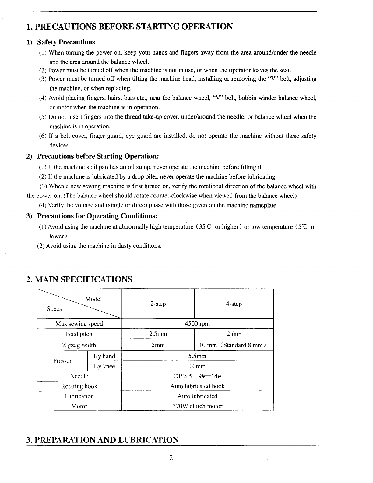
2.
MAIN SPECIFICATIONS
s
2-step
~
Max.sewing speed
Feed pitch
Zigzag width 5mm IOmm C Standard 8
Presser
Needle
Rotating hook Auto lubricated hook
Lubrication Auto lubricated
Motor 370W clutch motor
By hand
By knee IOmm
2.5mm
4500rpm
DPX5
35
5.5mm
9#-14#
·c
or higher) or low temperature ( 5
4-step
2mm
mm)
·c
or
3. PREPARATION AND LUBRICATION
-2-
1) Cleaning the machine
Before leaving the factory, the machine
parts are coated with rust-preventive grease,
which may be hardened and contaminated by
dust during storage and shipment. This grease
must be removed with gasoline.
2)
Examination
Though every machine is confirmed by
strict inspection and test before leaving the
factory, the machine parts may be loose or
deformed after long distance transportation with
jolt. A thorough examination must be performed
after cleaning the machine. Turn the balance
wheel to see if there
parts collision, uneven resistance or abnormal
noise. If these exist, adjustment must be made
accordingly before run-in operation.
is
running obstruction,
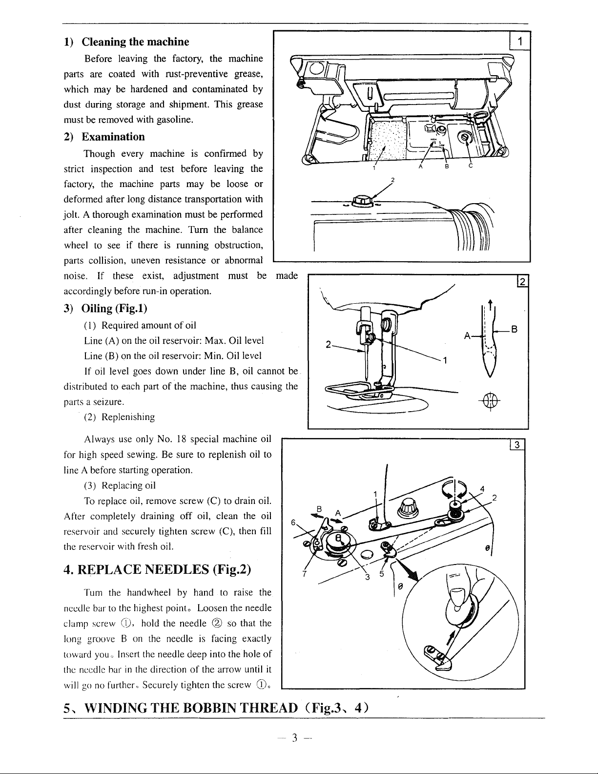
3) Oiling (Fig.l)
(I)
Required amount
Line (A) on the oil reservoir: Max.
Line (B) on the oil reservoir: Min.
If oil level goes down under line B, oil cannot be
distributed to each part
parts a seizure.
(2) Replenishing
of
oil
Oil level
Oil level
of
the machine, thus causing the
A
.t
I
!
2
B
18
Always use only No.
for high speed sewing. Be sure to replenish oil to
line A before starting operation.
(3) Replacing oil
To
replace oil, remove screw (C) to drain oil.
After completely draining
reservoir and securely tighten screw (C), then fill
the reservoir with fresh oil.
4.
REPLACE NEEDLES (Fig.2)
Tum the handwheel by hand to raise the
needle bar
clamp screw
long groove B on the needle
toward
the needle har
will go
5,
to
the highest pointo Loosen the needle
(1),
hold the needle @ so that the
you" Insert the needle deep into the hole
in
the direction
no
further" Securely tighten the screw
WINDING
THE
special machine oil
off
oil, clean the oil
is
facing exactly
of
of
the arrow until it
CDo
BOBBIN THREAD (Fig.3,
3
4)
- 3
--
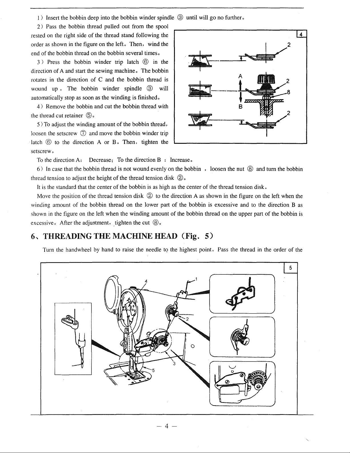
1 ) Insert the bobbin deep into the bobbin winder spindle ® until will
2)
Pass the bobbin thread pulled
of
rested on the right side
as
order
end
direction
rotates
wound up o The bobbin winder spindle
automatically stop
the thread cut retainer
loosen the setscrew
latch
setscrewo
thread tension to adjust the height
winding amount
shown
excessiveo After the
shown in the figure on the left o
of
the bobbin thread on the bobbin several timeso
Press the bobbin winder trip latch ® in the
3 )
of
A and start the sewing machineo
in
the direction
as
4)
Remove the bobbin and cut the bobbin thread with
5)
To
adjust the winding amount
® to the direction A
To
the direction A: Decrease; To the direction B : Increaseo
6)
In
case that the bobbin thread is not wound evenly on the bobbin , loosen the nut @ and turn the bobbin
It
is
the standard that the center
Move the position
of
in
the figure on the left when the winding amount
the thread stand following the
of
C and the bobbin thread is
soon as the winding is finishedo
®o
(J)
and move the bobbin winder trip
or
of
the thread tension disk ® to the direction A as shown in the figure on the left when the
the bobbin thread on the lower part
adju~tment,
out
from the spool
Then,
wind the
The
bobbin
® will
of
the bobbin thread,
B o
Then,
of
the thread tension disk ® o
of
the bobbin is
.tighten the cut
tighten the
as
high as the center
®o
of
the bobbin is excessive and to the direction B
of
the bobbin thread on the upper part
go
no further o
of
the thread tension disk o
of
the bobbin is
4
as
6-.
THREADINGTHEMACHINEHEAD (Fig.
Turn the handwheel by hand to raise the needle tq the highest pointe Pass the thread in the order
5)
of
the
-4-
numbers as illustratedo
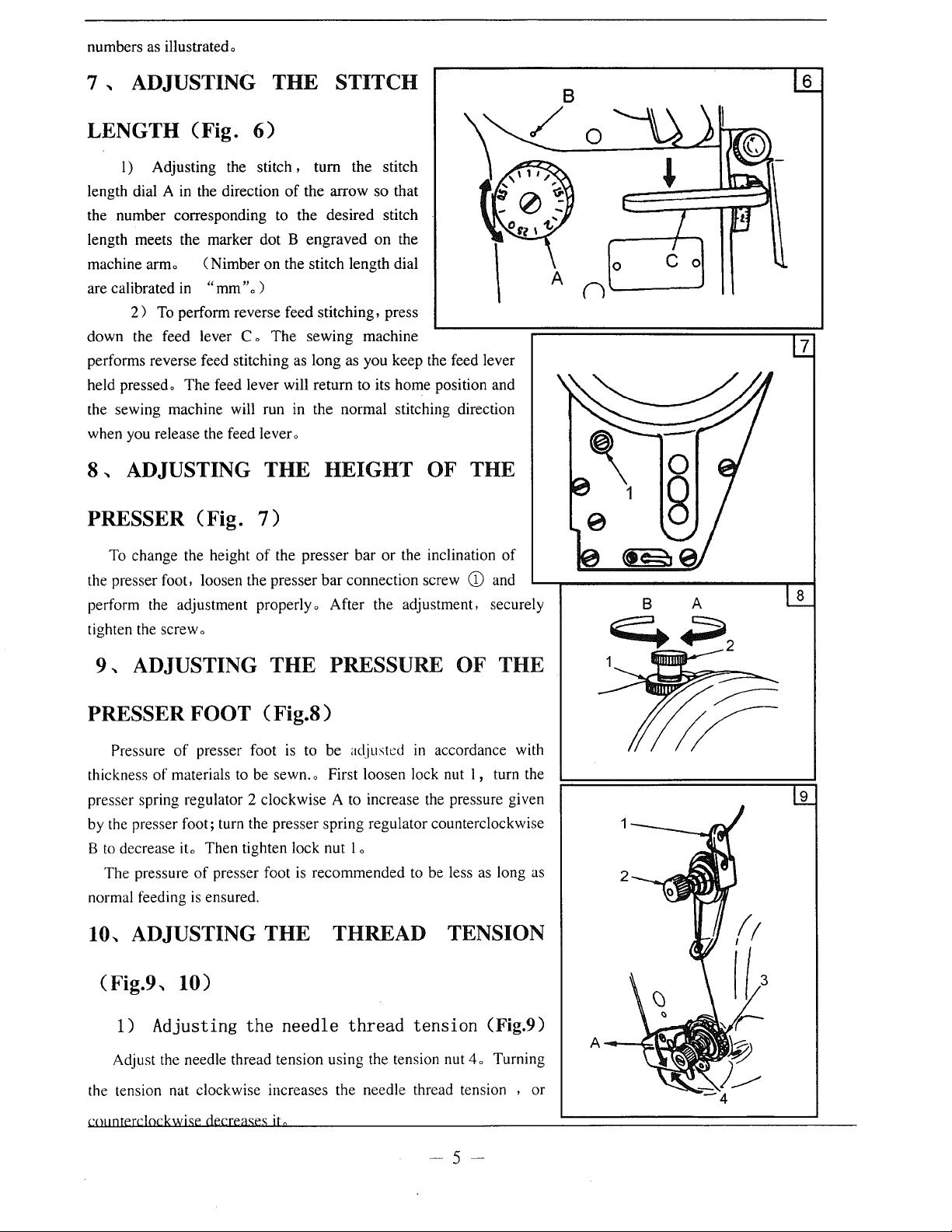
7 , ADJUSTING
LENGTH (Fig.
I) Adjusting the stitch , turn the stitch
length dial A in the direction
the number corresponding to the desired stitch
length meets the marker dot B engraved on the
machine armo ( Nimber on the stitch length dial
are calibrated in
2)
To
down the feed lever C o
performs reverse feed stitching as long as you keep the feed lever
held pressedo The feed lever will return to its home position and
the sewing machine will run in the normal stitching direction
when you release the feed lever o
8,
ADJUSTING
"mm
perform reverse feed stitching, press
PRESSER (Fig.
"o
6)
)
7)
THE
of
the arrow so that
The
sewing machine
THE
HEIGHT
STITCH
OF THE
A
6
0
(l'------J
7
To change the height
the presser foot, loosen the presser
perform the adjustment properly o After the adjustment, securely
tighten the screw o
9,
ADJUSTING
of
the presser bar or the inclination
bar
connection screw
THE
PRESSURE
CD
OF
of
and
THE
PRESSER FOOT ( Fig.S)
Pressure
thickness
presser spring regulator 2 clockwise A to increase the pressure given
by the presser foot; turn the presser spring regulator counterclockwise
B
to
decrease
The pressure
normal feeding
10,
(Fig.9,
of
presser foot
of
materials to be sewn. o First loosen lock nut I , turn the
ito
Then tighten lock nut 1 o
of
presser foot
is
ensured.
ADJUSTING
is
to be adjusted
is
recommended to be less as long as
THE
in
accordance with
THREAD TENSION
10)
8
9
1) Adjusting
Adjust the needle thread tension using the tension nut
the tension nat clockwise increases the needle thread tension , or
coJmterc!ockwise
the
decreases
needle
ita
thread
tension
4o
(Fig.9)
Turning
-5-
10
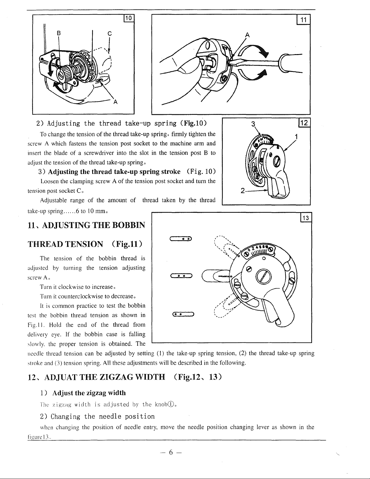
2)
Adjusting
To change the tension
screw A which fastens the tension post socket to the machine
insert the blade
adjust the tension
3)
Adjusting the
Loosen the clamping screw A
tension post socket Co
Adjustable range
take-up spring ..
11,.
ADJUSTING
the
thread
of
the thread take-up spring, firmly tighten the
of
a screwdriver into the slot in the tension post B to
of
the thread take-up spring o
thread
of
the amount
00
••
6 to 10 mmo
THE
take-up
take-up
of
the tension post socket and turn the
of
spring
spring
thread taken by the thread
stroke (Fig.
(Fig.lO)
BOBBIN
( •
·>
arm
and
10)
2--~
THREAD TENSION (Fig.11)
The tension
aJjusted by turning the tension adjusting
screw
Ao
Turn
it
Turn
it
It
is
common practice to test the bobbin
test the bobbin thread
Fig.!
I.
Hold the
delivery eye. If the
slowly. the proper tension
needle thread tension can be adjusted by setting
stroke and (3) tension spring. All these adjustments will be described in the following.
of
the bobbin thread is
clockwise to increaseo
counterclockwise to decreaseo
ten~ion
end
of
bobbin
as shown in
the thread from
case
is falling
is
obtained.
The
( . .
(-.=•.....;:•:..---J
(I)
the take-up spring tension, (2) the thread take-up spring
3
12
---=-~
13
12,.
ADJUAT
1)
Adjust the zigzag width
The
1.igzag
2) Changing
when changing the position
ri~ure
13'
THE
width
the
ZIGZAG WIDTH (Fig.12,.
is
adjusted
needle
by
the
knobCDo
position
of
needle entry, move the needle position
13)
-6-
changing
lever as shown in the
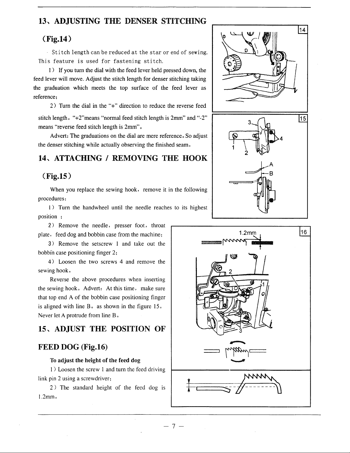
13, ADJUSTING THE DENSER STITCHING
(Fig.14)
14
Stitch
This
feature
1 )
feed lever will move. Adjust the stitch length for denser stitching taking
the graduation which meets the top surface
reference;
2)
stitch lengtho
means "reverse feed stitch length is 2mm" o
Advert: The graduations on the dial are mere referenceo So adjust
the denser stitching while actually observing the finished seamo
length
If
you tum the dial with the feed lever held pressed down, the
Tum the dial in the
"+2"means "normal feed stitch length
is
can
used
be
reduced
for
"+"
at
the
star
or
end
of
sewing.
fastening
direction to reduce the reverse feed
stitch.
of
the feed lever as
is
2mm" and "-2"
14, ATTACHING I REMOVING THE HOOK
(Fig.15)
When you replace the sewing hook, remove it in the following
procedures:
I ) Tum the handwheel until the needle reaches to its highest
position ;
2 ) Remove the needle , presser foot, throat
plate, feed dog and bobbin case from the machine;
3 ) Remove the setscrew 1 and take out the
bobbi'n case positioning finger 2;
4)
Loosen the two screws 4 and remove the
sewing hooko
Reverse the above procedures when inserting
the sewing hook o Advert: At this time, make sure
of
that top end A
is
aligned with line B o as shown in the figure
Never let A protrude from line B o
the bobbin case positioning finger
15
o
W!!/d/d/d!AJ~
1.2mm
15
4
16
15, ADJUST THE POSITION OF
FEED DOG (Fig.16)
To
adjust
I ) Loosen the screw I and tum the feed driving
link pin 2 using a screwdriver;
2 ) The standard height
1.2mmo
the height
of
the feed dog
of
the feed dog is
-7-
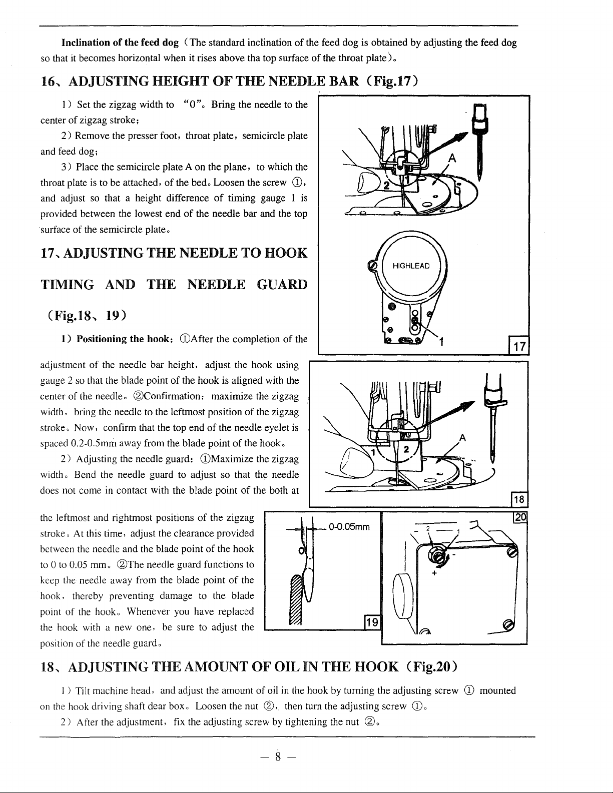
Inclination
so that it becomes horizontal when it rises above tha top surface
16-.
ADJUSTING HEIGHT
of
the
feed
dog
(The
standard inclination
OF
THE NEEDLE BAR (Fig.17)
of
the feed dog is obtained by adjusting the feed dog
of
the throat
plate)
o
1 ) Set the zigzag width to
of
center
and feed dog;
throat plate
and adjust so that a height difference
provided between the lowest end
surface
17
TIMING
zigzag stroke;
2)
Remove the presser foot, throat plate, semicircle plate
Place the semicircle plate A on the plane, to which the
3 )
is
to be attached,
of
the semicircle plate o
..
ADJUSTING THE NEEDLE TO HOOK
AND
THE NEEDLE GUARD
"0
"o
Bring the needle to the
of
the bedo Loosen the screw (D,
of
timing gauge 1 is
of
the needle bar and the top
(Fig.18-. 19)
1)
Positioning
adjustment
gauge 2 so that the blade point
center
width, bring the needle to the leftmost position
stroke o Now, confirm that the top end
spaced 0.2-0.Smm away from the blade point
width o Bend the needle guard to adjust so that the needle
does not come
of
of
the needleo
2)
Adjusting the needle guard: (!)Maximize the zigzag
the
hook:
the needle bar height, adjust the hook using
®Confirmation:
in
contact with the blade point
(DAfter the completion
of
the hook is aligned with the
maximize the zigzag
of
the zigzag
of
the needle eyelet
of
the hooko
of
the both at
of
is
the
of
the leftmost and rightmost positions
stroke o At this time, adjust the clearance provided
between the needle and the blade point
to 0 to
keep the needle away from the blade point
hook, thereby preventing damage to the blade
point
the hook with a new one. be sure to adjust the
position
18-.
on
0.05
mmo
®The
needle guard functions to
of
the hooko Whenever you have replaced
of
the needle guardo
ADJUSTING THE AMOUNT OF OIL IN THE
I ) Tilt machine head, and adjust the amount
the
hook driving shaft dear boxo Loosen the nut
2)
After the adjustment, fix the adjusting screw by tightening the nut
the zigzag
of
the hook
of
the
HOOK
of
oil in the hook by turning the adjusting screw
@,
then turn the adjusting screw
-8-
®o
(Fig.20)
CDo
CD
mounted
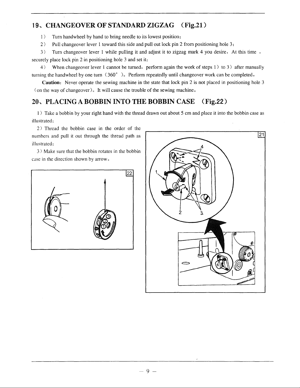
19,
CHANGEOVER
1)
Turn handwheel by
2)
Pull changeover lever 1
3)
Turn changeover lever 1 while pulling it and adjust it to
securely place lock pin 2 in positioning hole 3 and set it:
4)
When changeover lever 1
turning the handwheel by
Caution:
(on
the way
Never operate the sewing machine in the state that lock
of
changeover)
hand
one
turn C360o
o It will
OF
STANDARD ZIGZAG (Fig.21)
to bring needle to its lowest position;
toward
this side and pull out lock pin 2 from positioning hole 3;
zigzag
cannot
be turned, perform again
)o
Perform repeatedly until
cause
the trouble
of
the
changeover
pin
the sewing machineo
mark
4 you desire, At this time ,
work
of
steps 1 ) to 3 ) after manually
work
can
2 is not placed in positioning hole 3
20, PLACING A BOBBIN INTO THE BOBBIN CASE (Fig.22)
be completedo
1 ) Take a bobbin by your right
illustrated;
2)
Thread the bobbin case in the order
numbers and pull it out through the thread path as
illustrated:
3)
Make sure that the bobbin rotates in the bobbin
case
in
the direction shown by arrow o
hand
with the thread drawn
of
the
22
out
about 5
em
and place it into the bobbin case as
21
~9~
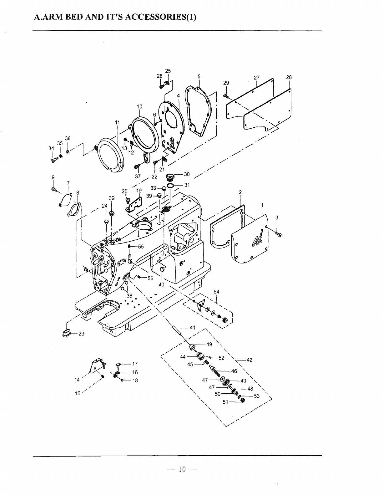
A.ARM BED AND
IT'S
ACCESSORIES(l)
-10-
 Loading...