

HIGH
LEAD
GA2698-1
Long
Arm
Cylinder Bed Transverse Seam
Lockstitch Sewing Machine
Instruction Manual
Parts
CatalOg
SHANGHAI HUIGONG
N0.3
SEWING MACHINE FACTORY

Instruction Manual
1,
PRECAUTIONS
(1)
Safety
(2)
Precautions
(3)
Precautions
2,
MAIN
SPECIFICATION
3,
PREPARATION
(1)
Cleaning
(2)
Examination · · · · · · · · · · · · · · · · · · · · · · · · · · · · · · · · · · · · · · · · · · · · · · · · · · · · · · · · · · · · · · · · · · · · · · 3
(3)
Lubrication
BEFORE
Precautions
before
for
FOR
OPERATION
the
machine · · · · · · · · · · · · · · · · · · · · · · · · · · · · ·
· · · · · · · · · · · · · · · · · · · · · · · · · · · · · · · · · · · · · · · · · · · · · · · · · · · · · · · · · · · · · · · · · · · · · · 3
--- CONTENT ---
STARTING
Operating
· · · · · · · · · · · · · · · · · · · · · · · · · · · · · · · · · · · · · · • • · • · · · · · · · · · · · · · · · · · · · · · · · · · 2
OPERATION
· · · · · · · · · · · · · · · · · · · · · · · · · · · · · · · · · · · · · · · · · · · · · · · · 2
· · · · · · · · · · · · · · · · · · · · · · · · · · · · · · · · · · · · · · · · · · · · · · · · · · · · · · · · · · · · · · · 2
Starting
Operation
Conditions
· · · · · · · · · · · · · · · · · · · · · · · · · · · · · · · · · · · · · · · · · · · · · · · · · · · · · · · · · · · · 3
· · · · · · · · · · · · · · · · · · · · · · · · · · · · · · · · · · · · · · · · · · · · · 2
· ·
·· ·· ·· · ··
· · · · · · · · · · · · · · · · · · · ·
'.
· · · · · · · · · · · · · · · · · · · · · · · · · · · · · · · 3
··
· · · · · · · · · · · · 2
Testing
(4)
4,
REPLACE
5,
WINDING
6,
ADJUSTMENT
(1) In
NEEDLES
OF
case
(2) Winding amount
(3)
Winding
7,
THREADING
8,
REMOVING
(1)
Removing · · · · · · · · · · · · · · · · · · · · · · · · · · · · · · · · · · · · · · · · · · · · · · · · · · · · · · · · · · · · · · · · · · · · · · · · · · 5
(2)
Installation······································································
9,
ADJUSTING
(1) Tension
(2) Tension
10,
ADJUSTMENT
· · · · · · · · · · · · · · · · · · · · · · · · · · · · · · · · · · · · · · · · · · · · · · · · · · · · · · · · · · · · · · · · · · · · · · · · · · 3
· · · · · · · · · · · · · · · · · · · · · · · · · · · · · · · · · · · · · · · · · · · · · · · · · · · · · · · · · · · · · · · · · · · · · · 4
BOBBIN
OF
of
strength
· · · · · · · · · · · · · · · · · · · · · · · · · · · · · · · · · · · · · · · · · · · · · · · · · · · · · · · · · · · · · · · · · · · · · · · · · · · · · 5
AND
THE
of
of
OF
THE
THREAD
BOBBIN
· · · · · · · · · · · · · · · · · · · · · · · · · · · · · · · · · · · · · · · · · · · · · · · · · · · · · · · · · · · · · 4
WINDER
· ·
..
· ·
..
· · · · ·
.... · ..
· · · · · · ·
..
· · · · ·
..
· · · · · · · · ·
..
· · · · · · · 4
uneven winding · · · · · · · · · · · · · · · · · · · · · · · · · · · · · · · · · · · · · · · · · · · · · · · · · · · · · · · · 4
of
thread
· · · · · · · · · · · · · · · · · · · · · · · · · · · · · · · · · · · · · · · · · · · · · · · · · · · · · · · · · 4
· · · · · · · · · · · · · · · · · · · · · · · · · · · · · · · · · · · · · · · · · · · · · · · · · · · · · · · · · · · · · · · · · · 4
INSERTING
THREAD
the
the
PRESSER
THE
TENSION
Upper
Lower
FOOT
BOBBIN
thread
thread
PRE~SURE
· · · · · · · · · · · · · · · · · · · · · · · · · · · · · · · · · · · · · · · · · · · · · · · · · · · · · 5
· · · ·
..
· ·
· · · · · · · · · · · · · · · · · · · · · · · · · · · · · · · · · · · · · · · · · · · · · · · · · · · · · · · 5
· · · · · · · · · · · · · · · · · · · · · · · · · · · · · · · · · · · · · · · · · · · · · · · · · · · · · · · 5
..
· ·
..
· · ·
............
....
· · · · · · · ·
·
.... · ...... · .... · ..................
..
· · · · · · · · ·
..
· · · · · · · · · · · · · · · · 5
· · 5
5
11,
ADJUSTMENT
12,
FEED
DOG
13,
ADJUSTING
14,
USINGOFTHEHANDWJ-IEEL
OF
HEIGHT
THE
STITCH
HEIGHT
LENGTH
· · · · · · · · · · · · · · · · · · · · · · · · · · · · · · · · · · · · · · · · · · · · · · · · · · · · · · · · · · · · · · · · · · · · · · 6
OF
AND
FORWARD/BACKWARD
THE
NEEDLE
····· · ······
SEWING
BAR
· · · · · · · · · · · · · · · · · · · · · · · · · · · · · · · · · · · · · · . · . · ·
····
............
·
......
Parts Catalog
.......•..............................................................
-1-
· · · · · · · · · · · · · · · · · · · · · · · · · · · · · · 6
...
6
······
..........
·
...........
6
7-27
1.
PRECAUTIONS
1)
Safety Precautions:
BEFORE
STARTING
OPERATION
( 1 ) When turning the
and the area around the balance wheel.
2)
Power must be turned
(
3)
Power must be turned
(
the machine, or when replacing.
4)
Avoid placing fingers, hairs, bars etc., near the balance wheel,
(
or motor when the machine
(
5)
Do not insert fingers into the thread take-up cover, under/around the needle, or balance wheel when the
is
machine
(
6)
If
a belt cover, finger guard, eye guard are installed, do not operate the machine without these safety
devices.
2)
Precautions before Starting Operation:
(
1)
If
the machine's oil pan has an oil sump, never operate the machine before filling it.
2)
If
(
(
the machine
3)
When a new sewing machine
in operation.
power
on, keep your hands and fingers away from the area around/under the needle
off
when the machine
off
when tilting the machine head, installing' or removing the
is
in
is
lubricated by a drop oiler, never operate the machine before lubricating.
is
is
not
in
use, or when the operator leaves the seat.
"V"
belt, bobbin winder balance wheel,
operation.
first turned on, verify the rotational direction
"V"
belt, adjusting
of
the balance wheel with
the power on. (The balance wheel should rotate counter-clockwise when viewed from the balance
wheel.)
4)
Verify the voltage and (single or' three) phase with those given on the machine nameplate.
(
3)
Precautions for Operating Conditions:
(
1)
Avoid using the machine at abnormally high temperature
lower) .
2)
Avoid using the machine in dusty conditions.
(
2.
MAIN
SPECIFICATIONS
Max. Speed(rpm)
Needle
Needle
Thread Take-up Lever Stroke(mm)
Presser-Foot Stroke
Bar
Stroke(mm)
Stitch Length(mm)
By
By
Hand
Knee
C35°C
or
higher)
.
or low temperature
800
DYX3
26#
56
96
7.5
13
20
(SOC
or
-2-
3. PREPARATION FOR OPERATION
1 ) Cleaning the machine
Before leaving the factory, the machine parts are coated with rust-preventive grease, which may be hardened
and contaminated by dust during storage and shipment. This grease must be removed with gasoline.
2)
Examination
Though every machine is confirmed by strict inspection and test before leaving the factory, the machine
parts may be loose or deformed after long distance transportation with jolt. A thorough examination must be
performed after cleaning the machine. Turn the balance wheel to see
If
collision, uneven resistance or abnormal noise.
run-in operation.
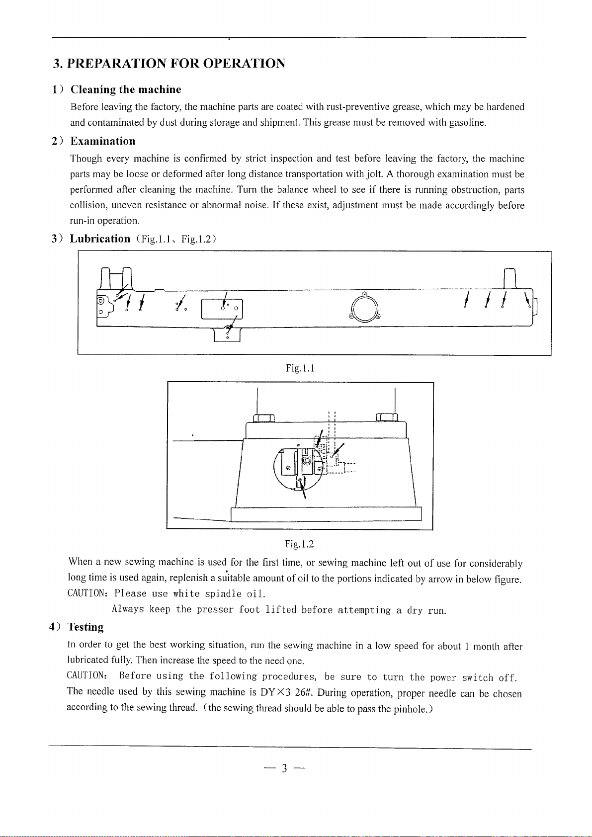
3)
Lubrication C
Fig.l.l,
Fig.1.2)
these exist, adjustment must be made accordingly before
if
there is running obstruction, parts
When a
long time
CAUTION:
new
sewing machine
is
used again, replenish a st{itable amount
Please
Always
use
keep
white
the
is
used for the first time, or sewing machine left out
spindle
presser
oil.
foot
lifted
0
Fig.l.l
Fig.l.2
of
oil to the pmiions indicated
before
attempting a dry
I I I
of
use for considerably
by
arrow
in
below figure.
run.
\
4)
Testing
In
order to get the best working situation, run the sewing machine in a low speed for about I month after
lubricated fully. Then increase the speed to the need one.
CAUTION:
The needle used by this sewing machine is DY X 3 26#. During operation, proper needle can be chosen
according to the sewing thread.
Before
using
the
(the
following
sewing thread should be able to pass the pinhole.)
procedures,
be
sure
-3-
to
turn
the
power
switch
off.
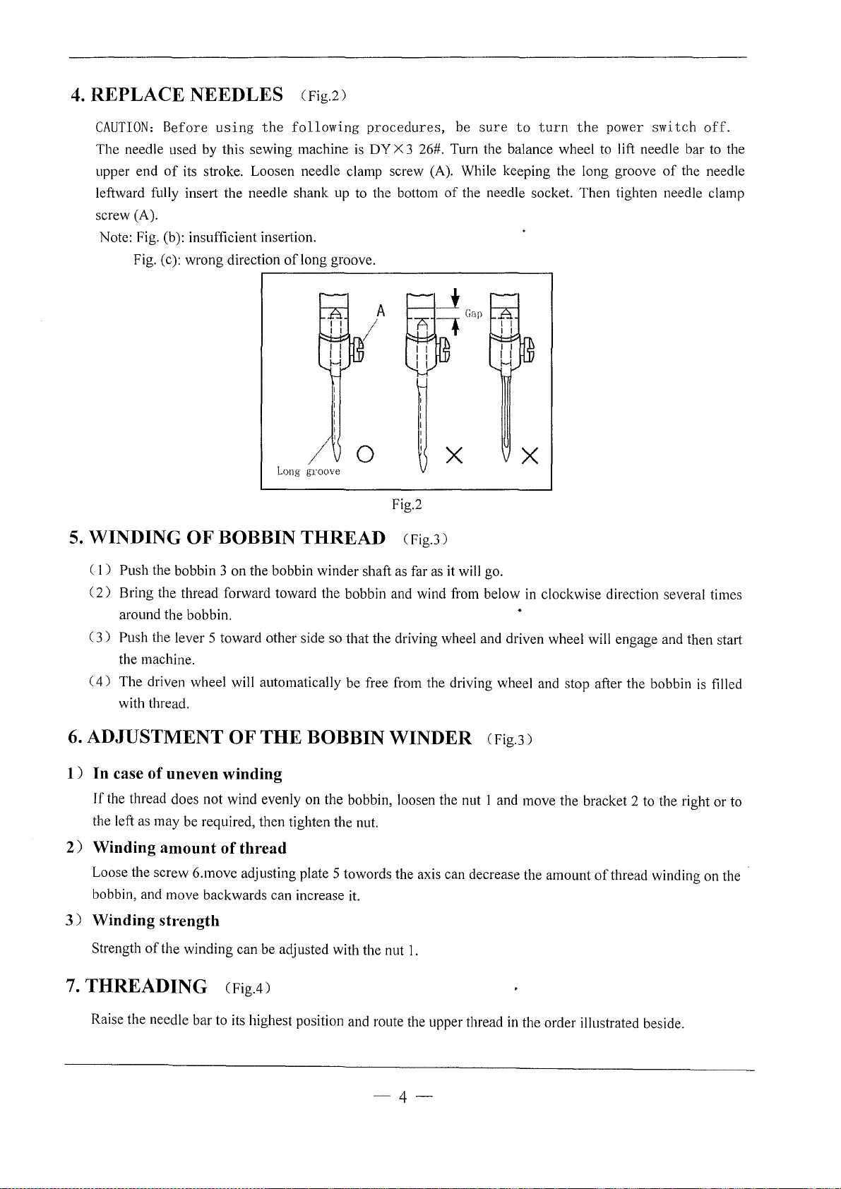
4.
REPLACE NEEDLES CFig.2)
CAUTION:
The
upper end
leftward fully insert the needle shank up to the bottom
screw (A).
Note: Fig. (b): insufficient insertion.
Before
needle used by this sewing machine
of
Fig. (c): wrong direction
using
its stroke. Loosen needle clamp screw (A). While keeping the long groove
the
of
following
long groove .
procedures,
is
DY
X 3 26#. Turn the balance wheel to lift needle bar to the
.-----------------------------,
Long
//
p·oove
0
Fig.2
be
sure
to
turn
the
power
of
the needle socket. Then tighten needle clamp
X
X
switch
of
the needle
off.
5.
WINDING OF BOBBIN THREAD CFig.3)
(
1)
Push the bobbin 3 on the bobbin winder shaft as far as it will go.
2)
Bring the thread forward toward the bobbin and wind from below in clockwise direction several times
(
around the bobbin.
C
3)
Push the lever 5 toward other side so that the driving wheel and driven wheel will engage and then start
the machine.
4)
The driven wheel will automatically be free from the driving wheel and stop after the bobbin
(
with thread.
6.
ADJUSTMENT OF THE BOBBIN WINDER CFig.3)
1)
In case
If
the left as may be required, then tighten the nut.
2)
Winding amount
Loose the screw 6.move adjusting plate 5 towards the axis can decrease the amount
bobbin, and move backwards can increase it.
3)
Winding strength
of
uneven winding
the thread does not wind evenly on the bobbin, loosen the nut I and move the bracket 2 to the right or to
of
thread
of
thread winding on the
is
filled
Strength
7.
THREADING CFig.4)
Raise the needle bar to its highest position and route the upper thread in the order illustrated beside.
of
the winding can be adjusted with the nut
1.
-4-
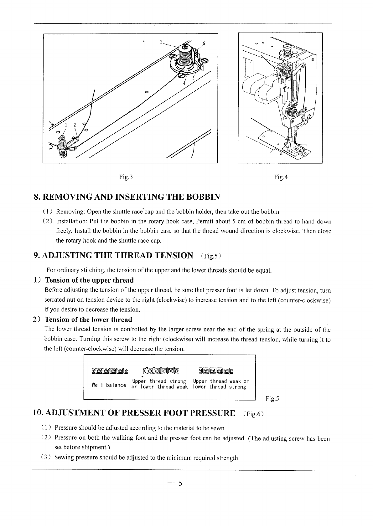
Fig.3
8.
REMOVING AND INSERTING THE BOBBIN
Fig.4
( 1 ) Removing:
(
2)
Installation: Put the bobbin
freely. Install the bobbin in the bobbin case so that the thread wound direction is clockwise. Then close
the rotary
9.
ADJUSTING THE THREAD TENSION CFig.5)
For ordinary stitching, the tension
1)
Tension
Before adjusting the tension
serrated nut
if
you desire to decrease the tension.
2)
Tension
The lower thread tension is controlled by the larger screw near the end
bobbin case. Turning this screw to the right (clockwise) will increase the thread tension, while turning
the left (counter-clockwise) will decrease the tension .
Open
the shuttle race' cap and the bobbin holder, then take
in
the rotary hook case, Permit about 5
hook
and the shuttle race cap.
of
the upper and the lower threads should be equal.
of
the upper thread
of
the upper thread, be sure that presser foot is let down. To adjust tension, turn
on
tension device to the right (clockwise) to increase tension and to the left (counter-clockwise)
of
the lower thread
out
the bobbin.
em
of
bobbin thread to hand down
of
the spring at the outside
.
Upper
Wei
I balance or
thread strong
lower
thread
weak
Upper
thread
lower
thread strong
weak
or
of
it
the
to
10. ADJUSTMENT OF PRESSER FOOT PRESSURE CFig.6)
Pressure should be adjusted according to the material to be sewn.
( 1 )
(
2)
Pressure
set before shipment.)
(
3)
Sewing pressure should be adjusted to the minimum required strength.
on
both the walking foot and the presser foot can be adjusted. (The adjusting screw has been
-5-
Fig.5
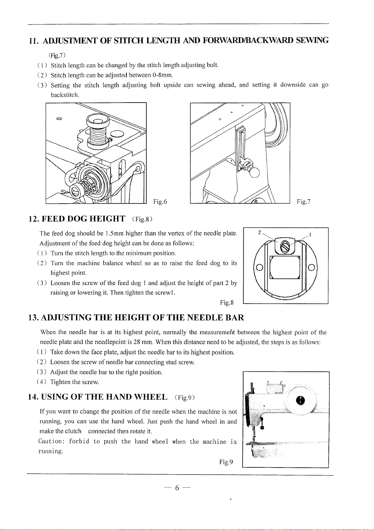
11.
ADIDS1MENT OF STITCH LENGTH AND
(Fig..7)
( 1 ) Stitch length can be changed by the stitch length adjusting bolt.
(
2)
Stitch length can be adjusted between 0-8mm.
(
3)
Setting the stitch length adjusting bolt upside can sewing ahead, and setting it downside can go
backstitch.
FORWARD/BACKWARD
SEWING
Fig.6
12. FEED
The feed dog should be 1.5mm higher than the vertex
Adjustment
( 1 ) Turn the stitch length to the minimum position.
2)
(
(
3)
13.
ADJUSTING
When the needle bar
needle plate and the needlepoint
( 1 ) Take down the face plate, adjust the needle bar to its highest position.
(
2)
3)
(
4)
(
DOG
Turn the machine balance wheel so as to raise the feed dog to its
highest point.
Loosen the screw
raising or lowering it. Then tighten the
Loosen the screw
Adjust the needle bar to the right position.
Tighten the screw.
HEIGHT
of
the feed dog height can be done as follows:
of
the feed dog 1 and adjust the height
THE
is
at its highest point, normally the measurement between the highest point
of
needle bar connecting stud screw.
CFig.8)
screwl.
HEIGHT
is
28 mm. When this distance need to be adjusted, the steps
OF
THE
of
the needle plate.
of
part 2 by
NEEDLE
Fig.8
BAR
Fig.7
is
as follows:
of
the
14. USING
If
you want to change the position
running, you can use the hand wheeL
make the clutch connected then rotate
Caution:
running.
OF
forbid
THE
to
HAND
push
the
WHEEL
of
the needle when the machine
just
it.
hand wheel when
CFig.9)
push the hand wheel in and
the
is
machine
Fig.9
-6-
not
is
•
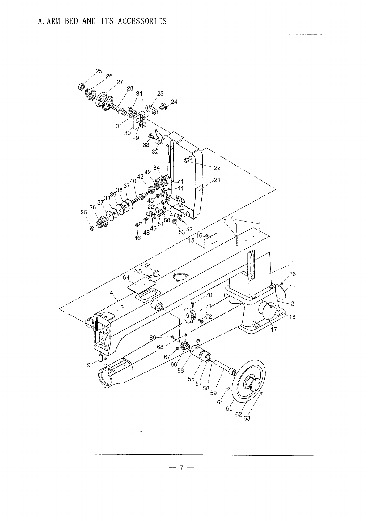
A.ARM
BED
ITS
AND
25
/ / 27
a;,
/ /
w
~~·~/24
ACCESSORIES
26
28
31
23
/~,,
31
~
30
29 /
33 /
~
-~,
(}
32
18
9
I
~~~~~
5S
I /
57
~
-7-
I , ·
5
59 1 ,
61
!"----17
60 1
62 63
'lP
1
I
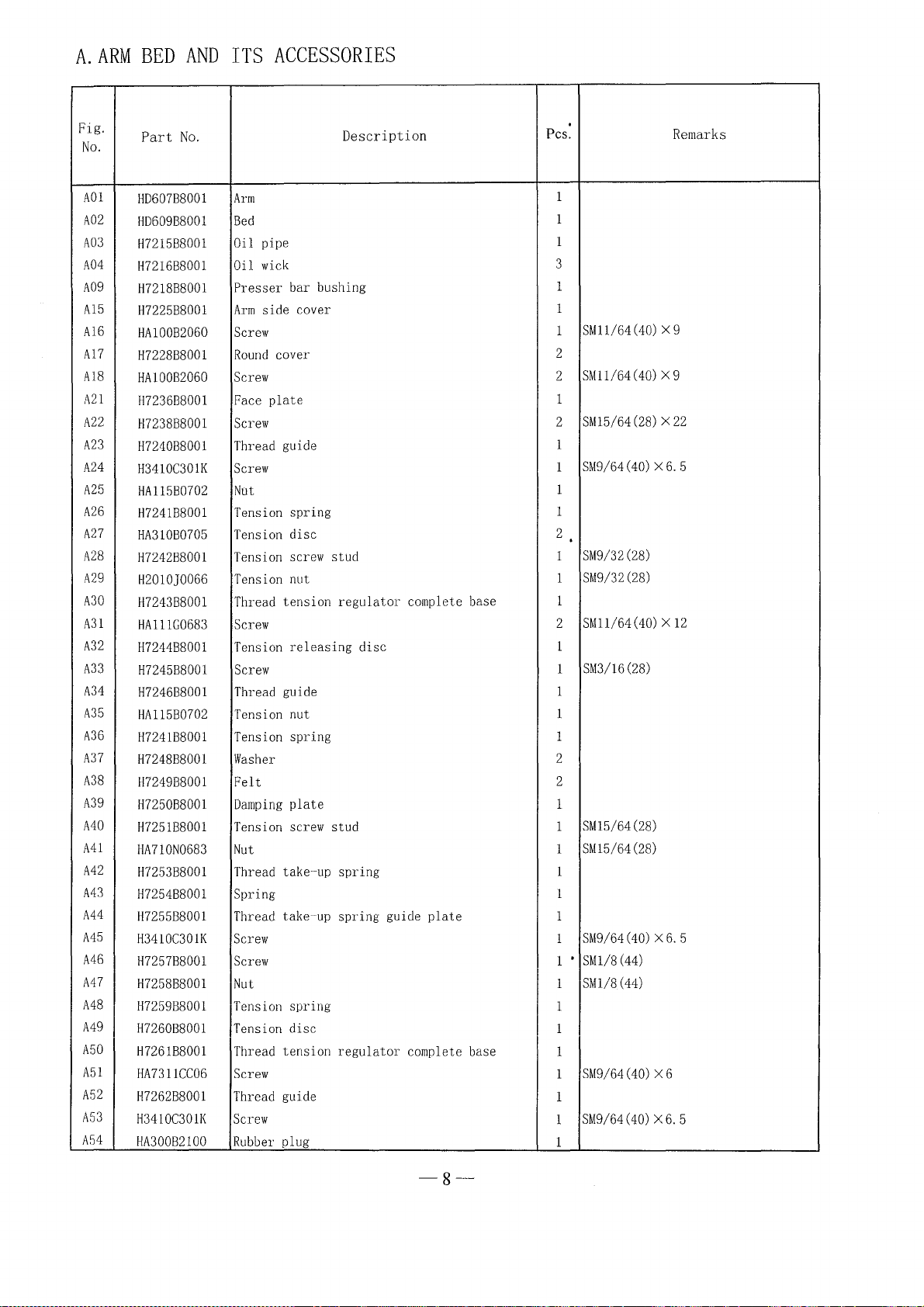
A.ARM
BED
AND
ITS
ACCESSORIES
Fig.
No.
A01
A02
A03
A04
A09
A15
A16
A17
A18
A21
A22
A23
A24
A25
A26
A27
A28
A29
A30
A31
A32
A33
A34
A35
A36
A37
A38
A39
A40
A41
A42
A43
A44
A45
A46
A47
A48
A49
50
A
A51
A
52
A
53
A
54
Part
No.
HD607B8001
HD609B8001
H7215B8001
H7216B8001
H7218B8001
H7225B8001
HA100B2060
H7228B8001
HA100B2060
H7236B8001
H7238B8001
H7240B8001
H3410C301K
HA115B0702
H7241B8001
HA310B0705
H7242B8001
H2010]0066
H7243B8001
HA111G0683
H7244B8001
H7245B8001
H7246B8001
HA115B0702
H7241B8001
H7248B8001
H7249B8001
H7250B8001
H7251B8001
HA710N0683
H7253B8001
H7254B8001
H7255B8001
H3410C301K
H7257B8001
H7258B8001
H7259B8001
H7260B8001
1-1726188001
HA7311CC06
1-1726288001
H3410C301K
HA300B2100
Description
Arm
Bed
Oil pipe
Oil
wick
Presser bar bushing
Arm
side cover
Screw
Round
cover
Screw
Face
plate
Screw
Thread guide
Screw
Not
Tension spring
Tension disc
Tension screw stud
Tension nut
Thread tension
Screw
Tension
Screw
Thread guide
Tension nut
Tension spring
Washer
Felt
Damping
Tension screw stud
Nut
Thread take-up spring 1
Spring 1
Thread
Screw
Screw
Nut
Tension spring
Tension disc
Thread tension
Screw
Thread guide
Screw
Rubber
releasing
plate
take-up spring guide
plug
regulator
disc
regulator
complete base
plate
complete base
Pes.
.
1
1
1
3
1
1
SMll/64
1
2
SMll/64
2
1
SM15/64
2
1
SM9/64(40)
1
1
1
2
.
SM9/32
1
SM9/32(28)
1
1
SM11/64(40) X 12
2
1
SM3/16(28)
1
1
1
1
2
2
1
SM15/64(28)
1
SM15/64
1
1
SM9/64(40)
1
'
SMl/8
1
1
1
1
1
1
1
1
1
(44)
SM1/8(44)
SM9/64(40)
SM9/64(40)
(40)
X 9
(40)
X 9
(28) X 22
X6.
(28)
(28)
X6.
X6
X6.
Remarks
5
5
5
-8-
 Loading...