

Page 1
HIGH
LEAD
GA2688-L
Long
Arm
Compound-Feed
Extral
Cylindrical Bed
Heavy Duty
Instruction Manual
Parts
Catalog
SHANGHAI HUIGONG
N0.3
SEWING MACHINE FACTORY
Page 2
1,
I'I~IT~l
~~r
1 J
(
2)
(
:1)
2,
VIAT\J
:1,
PREP.~RATION
4,
REPLACE
0,
111\DINGOFBOBBINTHREAD
fi,
:\D.Tl
(I)
(2)
C
:1)
7,
THRE:\DI"'G
i'L
I!I~Wl'v 1 ~c;
Y,
.\DJl'STI"iG
10,
11,
TIONS
SCi
f
~;tv
Precautions
Precautions
BEFORE
Precautions
before
for
SPECIFICATION
FOR
OPERATION
NEEDLES · .....
STMENT
In
case
OF
of
THE
uneven
Windingaruountofthread
Winding
strength
........................
AND
INSERTING
THE
THREAD
.\DWSTMENT
.\DJLSTMENT
OF
PRESSER
OF
WALKING
---
STARTING
.; · · · · · ·
OPERATION
;-.
· · · · · · · · · · •
Starting
Operating
Conditions
•·····•··•··•·••··
CONTENT
......................................................
.-.
· ·· · · · · · · · · · · · · · ·· · ·· · · · · · · · · · · · · · · · · · · · · · · · · · · · · · · · · · · · · · · · · · · · · · · · · · · · · 2
Operation
·•·••·•··•··•··•··•·•·•••··•··•··
·····································································
························•············································
---
······•··•··
···•····•
·····•···
..........................................................................................
···
......
•· · •·
· · · ·•· ·
......
··· ··· •··
......
•·· ··· ·· · ··· ···
•·
· ··· ···
...
•·
· ··· ··· ·
.............................................................................................
BOBBIN
WINDER
winding
•·
· · .. ··· ·· ·•··
.........
··· ... ··
....
··· ... · .. · .. · ·· · .. ·
....
.......................................................................................
..........................................................................................
...................................................................................................
··· ···
THE
TENSION
FOOT
FOOT
.......................................
BOBBIN
..............................................................................
.......................................................................................
PRESSURE
AND
.........
PRESSER
• ·
....... • ....
FOOT
...............................................................
· •
··· ···
.....................
.....
•·
· · · · .. · • .. · .. • · • · · · .. · · • · • · · •
···
............
•··
..................
.....
··•··· ··· •·· ... 4
· · .. •··
...........
•··
...............
..........
··· 2
2
2
2
3
4
· •·· 4
4
4
4
4
5
5
· ·.. 5
6
12,
ADjt:STMENT
1
:1,
FEED
14,
ADJUSTING
:l,
l S
I
DOG
I·\JG
HEIGHT
OF
THE
OF
THE
HAND
STITCH
.....
· ... ·
HEIGHT
WHEEL
LENGTH
AND
..... · ........
OF
THE
• .. · · ·
......
FORWARD/BACKWARD
·•·
............
NEEDLE
· .. · ·
BAR
........ · ....
•··
.................................
..................
· .. •
SEWING
..........
.............................. · ........
· · · · · · · .. · .. • · ·
··
...............................
• · · · · ·
.. · ....
· .. · .. · · · · · · ·
.... · .... · ......
.........
· .. ·
..............
•··
...
· · · · · · 6
· · ..
·..
6
6
7
-1-
Page 3
1.
PRECAUTIONS
1)
Safety Precautions:
(I)
When turning the power on, keep your hands and fingers away from the area around/under the needle
and the area around the balance wheel.
Power must
(2)
be
BEFORE
turned
off
STARTING OPERATION
when the machine is not in use, or when the operator leaves the seat.
Power must
(3)
the machine, or when replacing.
( 4) Avoid placing fingers, hairs, bars etc., near the balance wheel,
or motor when the machine is in operation.
Do
(5)
(
not insert fingers into the thread take-up cover, under/around the needle, or balance wheel when the
machine
6)
If
a belt cover, finger guard, eye guard are installed, do not operate
devices.
be
turned
is
in operation.
off
when tilting the machine head, installing
"V"
2) Precautions before Starting O.veration:
(I)
If
the machine's oil pan has an oil sump, never operate the machine before filling
(2)
lfthe
machine
(3) When a new sewing machine is first turned on, verify the rotational direction
the power on. (The balance wheel should rotate counter-clockwise
wheel)
( 4) Verify
the
is
lubricated
voltage and (single or three) phase with those given on the machine nameplate.
by
a drop oiler, never operate the machine before lubricating.
or
removing the
belt, bobbin winder balance wheel,
the
machine without these safety
ofthe
when
viewed from the balance
"V"
belt, adjusting
it.
balance wheel with
3) Precautions for Operating Conditions:
(I)
Avoid using the machine
lower) .
(2) Avoid using the machine in dusty conditions.
at
abnormally high temperature (
2 ~ MAIN SPECIFICATIONS
Max. Speed
Needle
Needle Bar Stroke
Thread Take-up Lever Stroke
Stitch Length
By
Hand
Presser-Foot Stroke
By Knee
35
800 rpm
DYX3
56
nnn
96
nnn
11
nnn
13
nnn
20nnn
·c
or higher) or low temperature ( 5
26#
·c
or
-2-
Page 4
3-..
PREPARATION
FOR
OPERATION
1 ) Cleaning the machine
Before leaving the factory, the machine parts are coated with rust-preventive grease, which may be
by
hardened and contaminated
2)
Examination
dust during storage and shipment. This grease must
be
removed with gasoline.
Though every machine
parts may be loose
performed after cleaning the machine. Turn the balance wheel
collision, uneven resistance or abnormal noise.
operation.
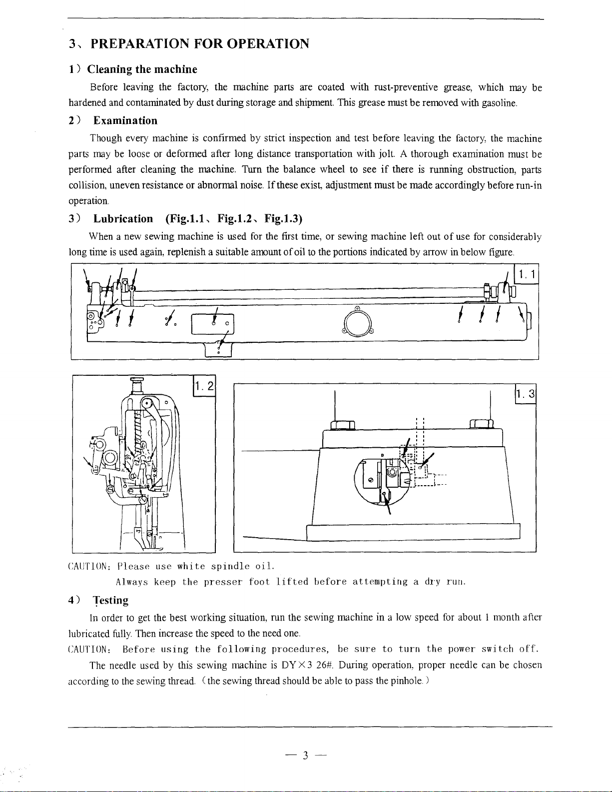
3)
Lubrication
When a new sewing machine
long time
is
used again, replenish a suitable amount
or
is
confirmed by strict inspection and test before leaving the factory, the machine
deformed after long distance transportation with jolt. A thorough examination must
If
these exist, adjustment must
(Fig.l.L
Fig.1.2-.. Fig.1.3)
is
used
for
the first time, or sewing machine left out
of
oil
to
the portions indicated by arrow in below figure.
to
see
0
if
there
is
running obstruction, parts
be
made accordingly before run-in
of
use for considerably
1.
be
3
CAUTION:
4)
lubricated
CAUTION:
according
Please
Always
use
keep
white
the
spindle
presser
oil.
foot
Testing
In
order
to
get the best working situation, run the sewing machine in a low speed
fully.
Then increase the speed
Before
The needle used by this sewing machine
to
the
using
sewing thread.
the
(the
to
the need
following
sewing thread should be able
lifted
one.
procedures,
is
DY
before
X 3
attempting
be
sure
26#.
During operation, proper needle can be chosen
to
pass the pinhole.)
-3-
to
turn
a
dry
run.
for
about 1 month after
the
power
switch
off.
Page 5
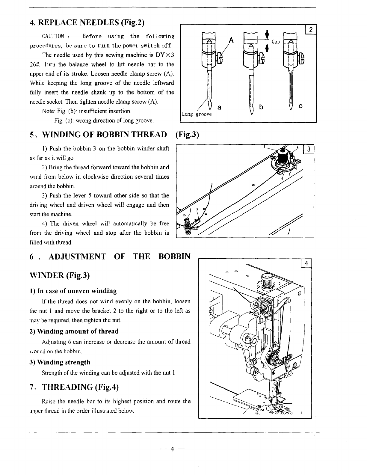
4.
REPLACE NEEDLES (Fig.2)
CAUTION
procedures,
The needle used
26#.
Turn the balance wheel to lift needle
upper end
While keeping the long groove
fully insert the needle shank up to the bottom
needle socket. Then tighten needle clamp screw (A).
5-.
as
far
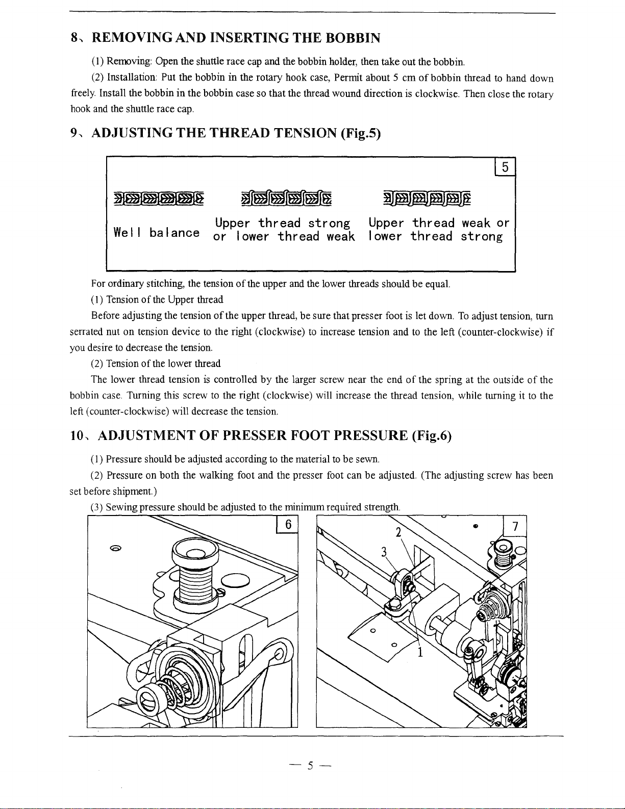
wind from below in clockwise direction several times
around the bobbin.
driYing
start the machine.
from
filled with thread.
of
its stroke. Loosen needle clamp screw (A).
Note: Fig. (b): insufficient insertion.
Fig. (c): wrong direction oflong groove.
WINDING
I) Push the bobbin 3 on the bobbin winder shaft
as
it will
2)
Bring the thread forward toward the bobbin and
3) Push the lever 5 toward other side so that the
wheel and driven wheel will engage and then
4) The driven wheel will automatically
the driving wheel and stop after the bobbin is
:
be
go.
Before
sure
to
by
OF
using
turn
this sewing machine is DY X 3
BOBBIN
the
following
the
power
switch
bar
of
the needle leftward
THREAD
be
off.
to the
of
free
the
(Fig.3)
Long
groove
A
b
2
c
6
-.
ADJUSTMENT OF THE BOBBIN
WINDER (Fig.3)
I)
In
case
of
uneven
lf
the thread does not wind evenly on the bobbin, loosen
the nut I and move the bracket 2 to the right or to the left as
may
be
required, then tighten the nut.
2) Winding
Adjusting 6 can increase or decrease the amount
\\OUnd
on
the bobbin.
amount
3) Winding strength
Strength
7..
THREADING (Fig.4)
Raise the needle bar to its highest position and route the
upper thread
of
the winding can be adjusted with the nut
in
the order illustrated below.
winding
of
thread
of
thread
1.
-4-
Page 6
8...
REMOVING AND INSERTING
(
1)
Removing: Open the shuttle race cap and the bobbin holder, then take out the bobbin.
(2) Installation:
freely.
Install the bobbin in the bobbin case so that the thread wound direction is clockwise. Then close the rotary
hook
and
the shuttle race cap.
9
...
ADJUSTING
Put the bobbin
THE
in
the rotary hook case, Permit about 5 em
THREAD TENSION (Fig.5)
THE
BOBBIN
of
bobbin thread to hand down
5
I ance
For ordinary stitching, the tension
(1) Tension
Before adjusting the tension
serrated nut
you desire
(2) Tension
The lower thread tension
bobbin case. Turning this screw
left (counter -clockwise) will decrease the tension.
10-.
ADJUSTMENT
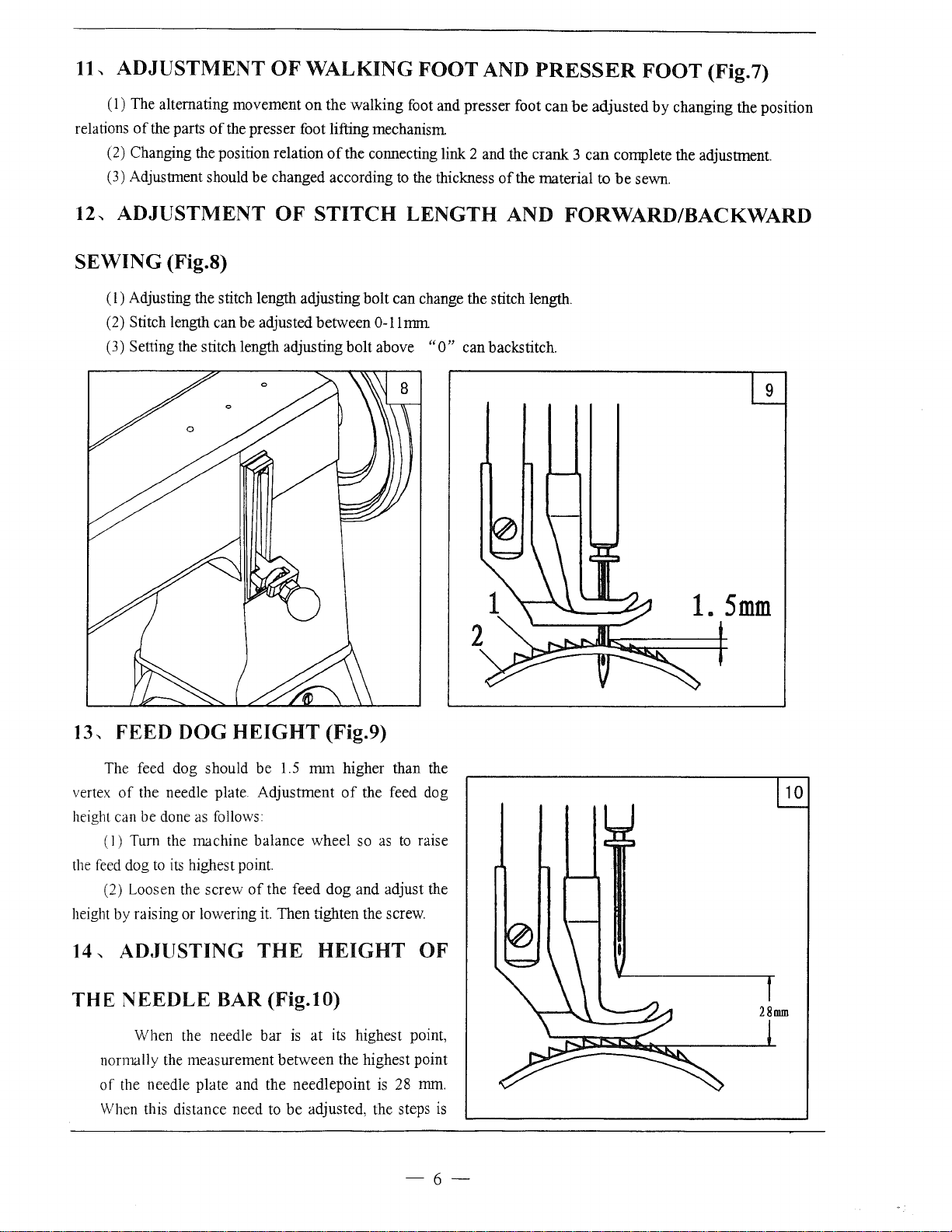
(I)
Pressure should
Pressure on both the walking foot and the presser foot can
(2)
set before shipment.)
Sewing pressure should be adjusted
(3)
of
the
Upper thread
on
tension device
to
decrease the tension.
of
the lower thread
be
or
of
the upper thread, be sure that presser foot
to
the right (clockwise)
is
controlled
to
the right (clockwise) will increase the thread tension, while turning it
OF
PRESSER
adjusted according to the material to
We
Upper
I I
ba
thread
lower
of
the upper and the lower threads should
by
to
the minimum required strength .
strong
thread
the larger screw near the end
FOOT
weak
to
increase tension and
PRESSURE (Fig.6)
.---------~~~--~~-------.--~
be
Upper
lower
sewn.
be
adjusted. (The adjusting screw has been
thread
thread
be
equal.
is
let down.
to
the left (counter-clockwise)
of
the spring at the outside
weak
or
strong
To
adjust tension, turn
of
to
if
the
the
-s-
Page 7
11"
ADJUSTMENT
OF
WALKING
FOOT
AND
PRESSER
FOOT
(Fig. 7)
(1) The alternating movement
relations
12.,
SEWING
of
the parts
(2) Changing the position relation
(3) Adjustment should be changed according
of
the presser foot lifting mechanism
ADJUSTMENT
(Fig.S)
(
1)
Adjusting the stitch length adjusting bolt can change the stitch length.
(2) Stitch length can be adjusted between
(3) Setting the stitch length adjusting bolt above
on
OF
the walking foot and presser foot can
of
STITCH
be
the connecting link 2 and the crank 3
to
the thickness
LENGTH
0-11
nnn
"0"
of
the material to
AND FORWARD/BACKWARD
can backstitch.
adjusted
can
by
changing the position
complete the adjustment.
be
sewn.
13, FEED DOG
The feed dog should be
vertex
of
the needle plate. Adjustment
height can be done
(I) Tum the machine balance wheel so
the
feed
dog
to
its
(2) Loosen the screw
height by raising or lowering
14
._
ADJUSTING
THE
NEEDLE
When the needle bar
normally the measurement between the highest point
of
the needle plate and the needlepoint
When this distance need to
HEIGHT
as
follows:
highest point.
of
the feed dog and adjust the
it.
THE
BAR (Fig.10)
(Fig.9)
1.5
mm
higher than the
of
the feed dog
as
Then tighten the screw.
HEIGHT
is
at its highest point,
is
be
adjusted, the steps
to
28
10
raise
OF
mm.
is
-6-
Page 8
as follows:
(
1)
Take down the face plate, adjust the needle
(2) Loosen the screw
(3) Adjust the needle
( 4) Tighten the screw.
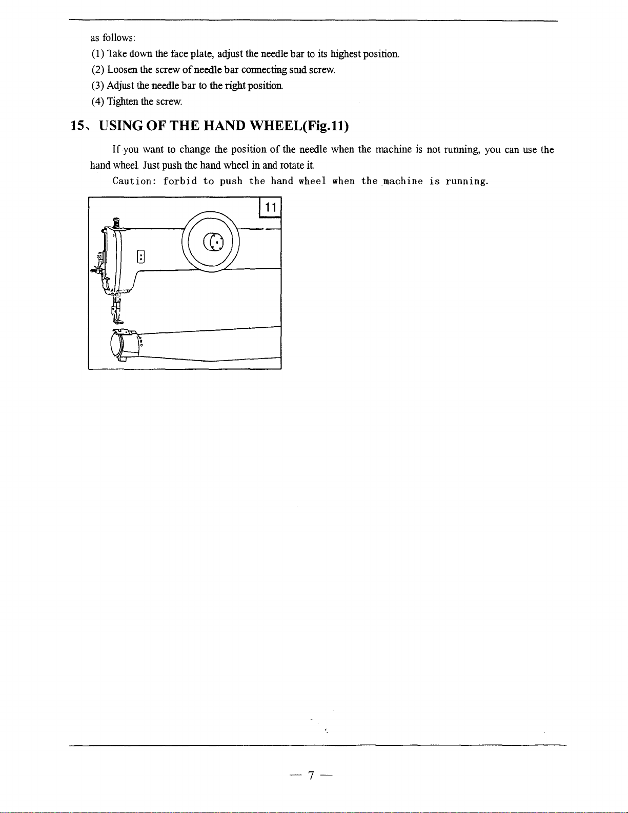
15-.
USING
If
hand wheel Just push the hand wheel in and rotate
OF
you want to change the position
Caution:
of
needle
bar
connecting stud screw.
bar
to
the right position.
THE HAND WHEEL(Fig.ll)
forbid
to
push
the
bar
to
its highest position.
of
the needle when the machine is not running, you can use the
it.
hand wheel
when
the
machine
is
running.
-7-
Page 9

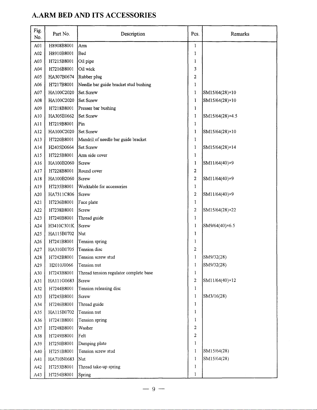
A.ARM BED AND ITS ACCESSORIES
25
/
(j)/'
26
2728
https://manualmachine.com/I
~/
31
~/24
/w..
31
--w
36
!
29 / f)
33 1
I
48
46
23
.......
,_
'·
32
-8-
2
18
Page 10
A.ARM BED AND ITS ACCESSORIES
Fig.
No.
A01
A02 H8910B8001 Bed 1
A03 H7215B8001
A04 H7216B8001
A05 HA307B0674 Rubber plug 2
A06 H7217B8001 Needle
A07 HA100C2020 Set Screw
A08 HA100C2020 Set Screw 1
A09 H7218B8001 Presser
A10 HA305E0662 Set Screw
All
Al2
Al3
A14
A15
A16
A17
A18
A19
A20
A21
A22
A23
A24
A25
A26
A27
A28
A29
A30
A31
A32
A33
A34
A35
A36
A37
A38
A39
A40
A41
A42
A43
Part No.
H8908B8001
H7219B8001 Pin
HA100C2020
H7220B8001
H2405D0664 Set Screw
H7225B8001 Ann side cover 1
HA100B2060
H7228B8001 Round cover
HA100B2060 Screw
H7235B8001 Worktable for accessories
HA7311C806 Screw
H7236B8001 Face plate
H7238B8001 Screw
H7240B8001 Thread guide
H3410C301K Screw
HA115B0702 Nut
H7241B8001 Tension spring
HA310B0705 Tension disc
H7242B8001
H2010J0066
H7243B8001
HA111G0683 Screw
H7244B8001
H7245B8001 Screw
H7246B8001 Thread guide
HA115B0702
H7241B8001
H7248B8001
H7249B8001 Felt
H7250B8001
H7251B8001
HA710N0683 Nut
H7253B8001
H7254B8001 Spring
Ann
pipe
Oil
wick
Oil
bar
guide bracket stud bushing 1
bar
bushing
Set Screw
Mandril.
Screw
Tension screw stud
Tension nut
Thread tension regulator complete base
Tension releasing disc
Tension nut
Tension spring
Washer
Damping plate
Tension screw stud
Thread take-up spring
of
needle bar guide bracket
Description
Pes.
Remarks
1
1
3
1 SM15/64(28)x10
SM15/64(28)xl0
1
1 SM15/64(28)x4.5
1
1 SM15/64(28)x10
1
1 SM15/64(28)x14
SM11/64(40)x9
1
2
2 SM11/64(40)x9
1
2 SM1l/64(40)x9
1
SM15/64(28) x22
2
1
SM9/64(40)x6.5
1
1
1
2
1 SM9/32(28)
1 SM9/32(28)
1
2 SM11/64(40)x12
1
1 SM3/16(28)
1
1
1
2
2
1
SM15/64(28)
1
SM15/G4(28)
1
1
1
-9-
Page 11
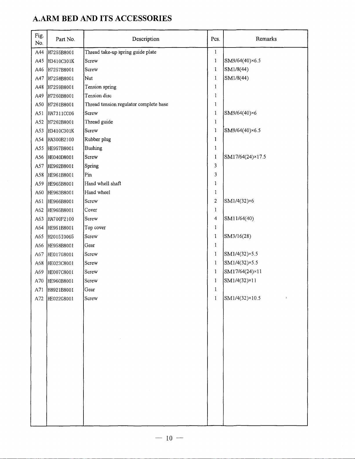
A.ARM BED AND ITS ACCESSORIES
Fig.
No.
A44
A45
A46
A47
A48
A49
ASO
A51
A 52
A53
Part
No.
H7255B8001
H3410C301K
H7257B8001
H7258B8001
H7259B8001
H7260B8001
H7261B8001
HA7311CC06
H7262B8001
H3410C301K
A 54 HA300B2100
A55
HE957B8001
HE040D8001
A56
A57
HE962B8001
A58
HE961B8001
A59
HE965B8001
A60 HE963B8001
A61
HE966B8001
A62
HE965B8001
A63
HA700F2100
A64
HE951B8001
A65
H2015I0065
A66
HE958B8001
A67
HE017G8001
A68 HE023C8001
A69
HE007C8001
A70 HE960B8001
A71
H8921B8001
A72
HE022G8001
Description
Thread take-up spring guide plate
Screw
Screw
Nut
Tension spring
Tension
Thread
Screw
Thread guide 1
Screw
Rubber
Bushing
Screw
Spring
Pin
Hand
Hand
Screw
Cover
Screw
Top cover
Screw
Gear
Screw
Screw
Screw
Screw
Gear
Screw
disc
tension
plug
whell
wheel
regulator complete base 1
shaft
Pes.
1
SM9/64(
1
1
SM1/8(44)
1
SMl/8(44)
1
1
SM9/64(
1
1
SM9/64(
1
1
SMI7/64(24)x17.5
1
3
3
1
1
SM1/4(32)x6
2
1
4
SMll/64(40)
1
SM3/16(28)
1
1
SMI/4(32)x5.5
1
SM1/4(32)x5.5
1
SM17
1
1
1
1
/64(24 )x
SM114(32)x11
SM1/4(32)x10.5
Remarks
40)x6.5
40)x6
40)x6.5
11
'
-10-
Page 12

B.NEEDLE BAR AND THREAD TAKE-UP MECHANISM
16
\d
~~
13 12
21~
-11-
Page 13

B.NEEDLE BAR AND THREAD TAKE-UP MECHANISM
Fig.
No.
B01
B02
B03
B04
B05
B06
B07
B08 H7210C8001
B09
B10 H4933K8001
Bll
B12
B13
B14 H7213C8001
B15
B16
B17
B18
B19
B20
B21
B22
B23
B24
B25
B26
B27
B28
B29
B30
B31
B32
B33
B34
B35
B36
B37 H7212B8001
B38
B39 H7211B8001
B40
Part
No.
H7204C8001
H7205C8001
H7206C8001
H8905C8001
HA108G0661
HA105D0662
H7209C8001
H403060120
H602040450
H7211C8001
H7212C8001
H7214C8001
H2010]0066
H007013050
H7215C8001
H2010]0066
H7216C8001
H7217C8001
H7218C8001
H7219C8001
HA700F2100
H7220C8001
H7222C8001
H7223C8001
H7224C8001
H7225C8001
H3208G0676
HA111G0683
H7226C8001
H415060140
H7213B8001
H2405D0664
H7214B8001
H2405D0664
H2405D0664
Description
Pulley
Screw
Screw
Arm
shaft
Collar
Set Screw
Thread take-up cam
Needle
bar
connecting base
Screw
Set
Screw
Pin
Thread take-up lever
Screw
Roller
Roller
pin
Nut
Retaining ring-E type
Needle bar connecting
Nut
Needle bar connecting
Needle bar connecting stud
Set Screw
Needle bar
Screw
Needle
Needle
bar
guide bracket
Needle bar guide bracket
Oil
wick
Needle
bar
guide bracket plate
Screw
Screw
Needle bar guide bracket plate base
Screw
Bushing
Set
Screw
Felt
Bushing
Set Screw
Bushing
Set Screw
link
link
link
screw
pin
screw
Pes. Remarks
1
SM5116(24)x19
1
SM5!16(24 )x 19
1
1
1
2
SM1/4(40)x6
1
1
GBff68
2
2 SM114(40)x10
GBff117
1
1
SM5116(24 )x7. 5
1
1
1
SM9/32(28)
1
GBff896
1
SM9/32(28)x11.5
1
SM9/32(28)
1
1
1
SM1/4(40)x4.5
2
1
SM11/64(40)x7
1
DY*3
1
1
1
1
1
SM15/64(28)x10.5
1
SM11/64(40)x12
1
1
GBff70.1
1
1
SM15/64(28)x14
1
3
1
SM15/64(28)x14
1
1
SM15/64(28)x14
1
M6x12
4x45
5
26#
M6x14
,
-12-
Page 14

C.LOWER SHAFT MECHANISM
19
20 \
\~
I/\/
0
40
---7
36
-
13-
~
\
\
31
Page 15

C.LOWER SHAFT MECHANISM
Fig.
No.
COl
C02
C03
C04
cos
C06
C07
cos
C09
C!O
Cll
C12
C13
C14
C15
C16
C17
Cl8
C!9
C20
C21
C22
C23
C24
C25
C26
C27
C28
C29 11722708001
C30 H602040180
C3!
C32 11722908001
C33
C34
C35
C36
C37 H72340800l
C38
C39
C40
C41
C42
C43
Part No. Description
8720408001
8720508001
8720608001
8415060250
H4728H8001
8723708001
8720708001
H2000B2050
8720808001
H720908001
H721008001
H721108001
H72!308001
H721408001
H721508001
H72!608001
H2000M0120
H721808001
H72!908001
H722008001
H722208001
H415080200
H722308001
H722408001
H2010J0066
H890508001
HA108G0661
H723908001
H722808001
H7230D8001
11723108001
H723208001
11723308001
1-1723508001
1-1723608001
1-1723488001
HA3411D308
HAlOOC2020
H7230B8001
Pes.
Eccentric 1
Set Srew
pin
Screw
Washer
Bearing 1
Eccentric cover
Screw
Crank
connecting rod 1
connecting
Crank
Pin
Screw
Shuttle shaft
Plate
Plate
Screw
Nut
Inside Shaft
Oil
wick
Rivet
Lower shaft crank
Screw
Shuttle shaft slide block
Screw
Nut
Lower shaft
Collar
Set Screw
Shuttle driver
Pin
Bobbin
Shuttle race body
Shuttle race back ring
Screw
Spring
Shuttle race cap
Screw
Spring
Screw
Bushing
Set Screw
Set Screw
Bushing
rod
pin
SM15/64(28)x12
1
2
GBff70.1
2
2
K43x48x17(N1N)
1
2
SM11/64(
1
1
SM3/16(32)x18
1
I
1
1
SM11/64(40)
2
SM11/64(40)
2
I
I
I
I
GB/T70.1
1
I
1
SM9/32(28)
1
1
1
SM1/4(
2
1
GBff117
I
1
1
1
SM3/16(32)
2
2
1
2
SMl/8(44)
2
SM3/32(56)
2
1
SM15/64(28)x7
1
SM15/64(28)x
1
1
Remarks
M6x25
40)x9
M8x20
40)x3.5
4x18
10
-14-
Page 16

C.LOWER SHAFT MECHANISM
Fig.
No.
C44
C45
C46
C47
C48
Part No.
H2405D0664
H7229B8001
H2405D0664
H7240D8001
H7228D8001
Description
Set Screw
Bushing 1
Set Screw
Shuttle hook complete
Bobbin
Pes.
SM15/64(28)x
1
SM15/64(28)x14
1
KSP-204N C
1
1
Remarks
14
-fti:)C)
-15-
Page 17

D.FEEDING
MECHANISM
45
38
40 39
\ \
~~
0'
~"
52
40
.
51
24
I 25
J~
49
50
/¥~
~
26
)5
24
16-
-
Page 18

D.FEEDING MECHANISM
Fig.
No.
DOl
D02
D03
D04
DOS
D06
D07
DOS
D09
DIO
Dll
D12
Dl3
Dl4
DIS
D16
Dl7
DIS
D19
D20
D21
D22
D23
D24
D2S
D26
D27
D28
D29
D30
D31
D32
D33
D34
D35
D36
D37
D3S
D39
D40
D41
D42
D43
Part
No.
H7205E800l
H7206E800l
H7207E8001
H2000B2050
H7208E8001
H7209E8001
H2010J0066
H7210E8001
H7211E800l
H415050140
H7212E8001
H7213E8001
HA104G0012
H7211D8001
H7214E800l
H7215E8001
H7216E8001
HE00001032
H7217E8001
H003008080
H7218E8001
H415060200
H7219E8001
H007013080
H8904E8001
HA!08G0661
H7239D8001
H7221E8001
H7222E8001
H7223E8001
H2013N0067
H7225E8001
H7226E8001
HA700F2100
H7219E8001
H007013080
H7227E8001
H7228E8001
H7239D8001
H7229E8001
H57!1G8001
H7230E8001
Description
Feed cam 1
Set Screw
Feed cam cover 1
Screw 2
Feed forked connection
Feed forked connection crank pin
Nut 1 SM9/32(2S)
Stitch length connecting link 1
Stitch length connecting link crank
Screw
Stitch length adjusting pin
Damping plate 1
Screw 2
Screw
Stitch length adjusting bolt
Stitch length limited plate 1
Nut
Metal ball 1
Spring
Plastic ball 1
Nut 1 GBff6172.1 MS
Feed driving rock shaft crank
Screw 2 GBfr70.1 M6x20
Feed driving rock shaft crank pin 2
Retaining ring-E type 2 GBfrS96 S
Feed driving rock shaft
Collar 1
Set Screw
Crank pin 1
Feed driving connecting link
Feed driving connecting link crank pin 1
Nut
Feed dog base 1
Feed dog 1
Screw
Feed lifting rock shaft crank pin
Retaining ring-E type 1 GBffS96 8
Feed lifting rock
Collar
Set
Screw
Feed dog base limited plate
Screw 2
Needle plate 1
shaH 1
pin
Pes.
SM1S/64(2S)x6
2
SM11/64(40)x9
1
1
1
1
GBfr70.1
MSxJ4
1
SM3/16(2S)x12
SM3/16(32)xJS
1
1
1
GBff30S 3.17S
1
JBff7271.1 MSx32
1
1
2 SM1/4(40)x3.S
1
1 SM1/4(24)
1 SM11/64(40)x7
I
1
2 SM1/4( 40)x3.5
1
SM!l/64(40)x6
Remarks
~~
-17-
Page 19

D.FEEDING MECHANISM
Fig.
No.
D44
D45 H7232E8001
D46 HA104F0654
D47
D48
D49
D50
D51
D52
Part
No.
H7231E8001
H7232B8001
HA100C2020
H7231B8001
HA3411D308
H7233B8001
H2405D0664
Description
Screw
Stitch length indicating plate
Screw
Bushing
Set Screw
Bushing 1
Set Screw 1
Bushing
Set Screw
Pes.
SM3/16(28)x9.5
2
1
SM15/64(28)x9
2
1
SM15/64(28)x
1
SM15/64(28)x7
1
SM15/64(28)x 14
1
Remarks
10
-
18-
Page 20

E.
UPPER SHAFT & PRESSER FOOT MECHANISM
7
~
8
20
21
19-------
6
5
11
22~
~
/~
fo
16
;!
5
8
4
13
-19-
Page 21

E.PRESSER FOOT MECHANISM
Fig.
No.
EOl H7204F8001
E02
E03
E04
E05 H7207F8001
E06 H7208F8001
E07 H7209F8001
E08 H7210F8001
E09
ElO
Ell
El2
El3
El4
E15
El6
El7
El8
E19
E20
E21
E22 H609030180
Part
No.
H7205F8001
HA710P0673
H7206F8001
H7211F8001
HA719B0709
H7212F8001
H7213F8001
H7214F8001
H7215F8001
H7217F8001
H7218C8001
H7219F8001
H7220F8001
H7221F8001
H7222F8001
Presser foot
Screw
Nut
Finger guard
Presser
bar
Presser
bar
spring
Thumb screw
Nut
Walking foot
Screw
Presser
bar
Screw
Presser
bar
lifting shaft
Washer
Collar
Set Screw
Plastic ball
Bolt
Presser
bar
guide bracket
Connecting rod
Screw
Pin
Description
Pes.
1
SM9/64(40)x14
1
SM9/64(40)
1
1
1
1
SMS/8(28)
1
SMS/8(28)
1
1
SM11/64(4Q)x7
1
1
SM9/64(40)
1
1
1
1
SM1/4(40)x4.5
2
JBm271.1
1
1
1
1
SMl/4(40)
1
GB!f879.1 3x18
1
Remarks
M6x20
-20-
Page 22

F. UPPER FEED LIFTING
7
~:
------
27
28
""
ROCK
---
9
~
SHAFT MECHANISM
4---_
I
I
L_
2 -
25
--
26
~
___
_
--?
/
3
'1
10
~
14
-21-
Page 23

F.
UPPER FEED LIFTING ROCK SHAFT MECHANISM
Fig.
No.
F01 H7204G8001
F02 HA307C0066
F03
F04 H7206G8001
FOS
F06
F07
F08
F09
FlO
F11
F12
F13
F14
F15
F16
F17
F18
F19
F2ll
F21
F22
F23
F24
F25
F26
F27
Fn
Part No.
H7205G8001
H7207G8001
H7208G8001
H7209G8001
H7210G8001
H7211G8001
H7212G8001
H415060140
H7213G8001
H7214G8001
11007013080
H7215G8001
H7214G8001
H7216G8001
HA104G0012
H7217G8001
H7221G8001
H7218G8001
H7219G800l
HA700B2060
H7220G800l
H7221B800l
HA3411D308
H7222B80lll
HA34llD308
Description
Presser foot lifting eccentric
Set
Screw
Eccentric connecting
Screw
Washer
Nut
Adjusting
Screw
Presser
Presser foot lifting shaft
Screw
Presser
Screw
Retaining ring-E type
Presser foot lifting lever
Screw
Presser
Screw
Roller
Bearing
Screw
Roller
Screw
Walking foot lifting connecting
Bushing
Set
Bushing
Set
crank
foot lifting shaft
foot lifting connecting
foot lifting lever
base
plate
Screw
Screw
link
crank
base
link
link
Pes.
1
SM114(40)x6
2
1
1
1
SM11/32(28)
1
1
SMS/16(18)
1
1
1
GBff70.1
1
1
2
GBff896
4
1
2
1
SM3116(28)x12
2
1
ISO
1
SM15/64(28)
1
1
SM3116(32)x8
2
1
1
SM15/64(28)x7
1
1
SM15/64(28)x7
1
Remarks
M6x14
8
K7
-22-
Page 24

G.NEEDLE BAR
19
20 \
ROCKING
8
\
MOTION
MECHANISM
9
\
13~
\o
\
18
~~
15
J'
18
I
17
1
-23-
Page 25

G.NEEDLE BAR ROCKING MOTION MECHANISM
Fig.
No.
GO!
G02 H7219E8001
G03 H007013080
G04 H7206H8001
G05
G06 H7208H8001
G07
G08 H8904H8001
G09 H7210H8001
G10 HA105D0662
G11 H7211H8001
G12 HA105D0662
G13
G14
GIS
Gl6
Gl7
G18
Gl9
G20
G21
G22
Part No.
H7204H8001
H7207H8001
H7210G8001
HA100C2070
H7212H8001
H7214G8001
H007013080
H7213H8001
H7214H8001
H7224B8001
HA3411D308
H7223B8001
HA3411D308
Description
Needle bar rocking connecting link
Screw
Retaining ring-E type
Adjusting crank
Adjusting crank base
Screw
Screw
Needle bar rock shaft
Collar
Set Screw
Needle bar rocking crank
Set Screw
Screw
Needle bar rocking connecting link
Screw
Retaining ring-E type
Screw base
Screw
Bushing
Set Screw
Bushing
Set Screw
Pes.
1
1
GB!T896
1
1
1
SM5/16(18)x24
1
SM5/16(18)x18
1
1
2
SM1/4(
4
1
SM1/4(40)x4.5
1
SM9/32(28)
1
1
2
GB!T896
2
1
SMll/64(
3
1
SM15/64(28)x7
1
1
SM15/64(28)x7
1
Remarks
8
40)x4.5
8
40)x4.5
-24-
Page 26

H.KNEE LIFTER MECHANISM
4
1
2
3
7
21
~1~
16~y
i
20
17
13
ft~llitl~lliJJ!IJ
f?.f!itlfj
IJ
-25-
Page 27

H.KNEE LIFTER MECHANISM
Fig.
No.
HOI
H02
H03
H04 H4910N8001
HOS
H06
H07
H08 H4921N8001
H09
HlO H8908I8001
Hll
Hl2
Hl3
H14
H15
Hl6
Hl7
Hl8
Hl9
H20
H21
H22
H23
H24
Part
No.
H8906I8001
H005008100
H007013060
H8907I8001
H005008080
H4922N8001
H4923N8001
H801045200
HA300J2230
H402040120
H005008040
H005005040
H8909I8001
H4915N8001
H4918N8001
H4924N8001
H402040300
H003002040
H8910I8001
H4917N8001
Description
Cylinder
Nut
Spring Washer
Cylinder
E type ring
Swing
Spring
Tube Fitting
Timing valve
PUTube
Bracket for filtration and decompression
Screw
Washer
Screw
Spring
Washer
Tube Fitting
Valve for filtration
Solenoid Valve
Silencer
Screw
Nut
PUTube
Tube Fitting
bar
Pin
Washer
washer
and
decompression 1
Pes.
1
GB!f6173
1
GB!f93
1
MAL25x50
1
GB!f896
1
1
1
GB!f93
<l>
1
1
<l>
2
<l>6(1.6m)
1
GB!T99 4.5x20
2
2
GB!f67
2
4
GB!f93
GB!T95 4
8
<1>8-1/4"
3
DC24V
1
2
GB!f67
2
4
GB!f6170
1
<l>
<l>
2
Remarks
M10x1.25
10
6
8
6-118"
6-1/8"
M4x12
4
M4x30
M4
8(0.2m)
6-1/4"
-26-
Page 28

I.KNEE
LIFTER
MECHANISM
7
\
9
1
~
6
5 3
-27-
Page 29

I.KNEE LIFTER MECHANISM
Fig.
No.
I01
I02
I03
I04 HA300J2280
lOS
I06
I07 H7205I8001
I08
I09 H7210I8001
IlO
Ill
Il2
l13
I14
Part No.
H7204!8001
H7205I8001
H7206I8001
H7207I8001
H8904I8001
H7209I8001
H7211I8001
H7212I8001
H7214I8001
HA300J2280
H7213I8001
Description
Knee lifter lever
Screw
Knee lifter lever base
Screw
Screw
Knee lifter rod
Screw
Coil spring
Screw
Screw
Washer
Knee lifter lever connecting plate
Screw
Screw
Pes.
2
SM15/64(28)x6
1
1
SM15/64(28)x8
2
SM15/64(28)
1
1
SM15/64(28)x6
2
1
SM11/64(40)x6
1
SM11/64(40)x4.5
1
1
1
SM15/64(28)x8
2
SM1/4(40)x3.5
1
Remarks
-28-
Page 30

J.BOBBIN WINDER MECHANISM
0-------------
1
11-----.
/29
~/30
31
14
19
----
Jf~~
-----32
~33
22~
:~~
~
#',/
e~,
r 4
24
I
/
/20
{[JJ]J
~23
5
9
-29-
Page 31

J.BOBBIN WINDER MECHANISM
Fig.
No.
JOl
J02 H6707N8001
J03 H6708N8001
]04
JOS
J06 H6713N8001
J07
J08
]09
JlO
Jll
Jl2
Jl3
Jl4
JlS
Jl6
J17
]18
J19
J20
J2l
J22
J23
J24
J25
J26
127
J28
J29
130
J3]
132
133
Part
No.
H6706N8001
H7210J8001
H7213J8001
H6714N8001
H6715N8001
H007013050
H7205J8001
H6717N8001
H6718N8001
H6719N8001
H6720N8001
HA100H2150
H7206J8001
H3200B2100
H6722N8001
H6723N8001
H6731N8001
H6732N8001
H6724N8001
H6725N8001
H7005D800l
H4723D800l
H3107G0662
H7208J8001
HA310B0705
HAll5B0702
HAll5B7010
H3300B2040
H6662B8001
H003008040
Description
Bobbin winder plate
Pin
Pin
Bobbin winder crank shaft
Bobbin winder crank
Bushing
Pin
Bobbin winder spring
Retaining ring-E type
Bobbin
winder
shaft
Bobbin base
Driven wheel
Friction rubber band
Bobbin winder lever
Screw
Winding length limited plate
Screw
Washer
Pin
Set Screw
Set Screw
Spring
Bobbin winder cam
Driving wheel
Set Screw
Screw
Screw
Tension disc
Nut
Limited plate
Spring
Thread guide
Nut
Pes.
1
1
1
1
1
2
1
1
GBtr896
2
1
1
1
1
1
SM9/64(40)x11
1
1
1
1
1
M5x6
1
GBtr
2
1
1
1
SM15/64(28)
2
SM11/64(40)
3
1
2
1
1
1
1
GBtr6172.1
2
80
Remarks
5
M3x4
M4
-30-
Page 32

K.ACCESSORIES(-)
7 8 7
1
5
6
~~4
$~3
9
13
I
17
~~~
I I I
10
15
11
12
20
0
-31-
~
/'
22
19~
21
~
Page 33

K.ACCESSORIES(-)
Fig.
'No.
K01
K02
K03
K04
KOS
K06
K07
K08
K09 HA800F2020
K10
Kll
K12
K13
K14
K15
K16
K17
K18
K19
K20
K21
K22
Part No.
H7207K8001
H7208K8001
H605030400
H34411C410
H7209K8001
H3215K0693
H7210K800l
H7211K8001
HB00001050
HB00001040
HB00001030
HA300J2070
HA300J2200
HA300J2210
HJ02090110
HJ02100130
H7228D8001
H7220C8001
HA200]2030
H200400069
H8904K8001
Description
Silicon oil
Cover
Pin
Screw
Spring
Screw
Thread guide
Nut
Screw
Hexagon socket screw key
Hexagon socket screw key
Hexagon socket screw key
Screw driver (size L)
Screw driver (size
Screw driver
Spanner
Spanner
Bobbin
Needle
Thread stand assy
Oiler
Vinyl cover
box
M)
(sizeS)
Pes.
1
1
GBffll9.2
1
SM9/64( 40)x4
1
1
SM9/64(40)x5
1
2
SM3/32(56)
2
SM15/64(28)
1
GBff5356
1
GBff5356
1
GBff5356
1
1
1
1
GBff4388
1
GBff4388
1
4
4
1
1
1
Remarks
3x40
5
4
3
9x11
10x13
-32-
Page 34

L.ACCESSORIES(
1
=)
11
13
2 5
3~~~~
. '
,_
-..::::~---14
''
'1
~----15
1!!1
-----16
1
2~~
r\\
I~
6
!
I ! I
~
t
1\r
~
10
'\
I 8
I
I
I
I
l__,
17
-33-
Page 35

L.ACCESSORIES(
=)
Fig.
No.
L01
L02
L03
L04
L05
L06
L07
L08
L09
LIO
L11
Ll2
Ll3
Ll4
LIS
Ll6
Ll7
Ll8
Ll9
L20
L21
Part No. Description
H415060140
Hl03080250
H8918K8001
H8917K8001
H415080160
H8924K7101
H8920K8001
H8913K8001
H8924K7101
H8918K8001
H8910K8001
Hl25100900
H8915K8001
H429120250
H005001100
H003002100
H8912K8001
Hl03120500
H005008120
H8916K8001
H8911K8001
Screw
Screw
Short rod
Long rod I
Screw
Large pedal 1
Long steel tube 1
Steel tube base
Small pedal
Short steel tube 1
Bedplate 1
Screw 4
Flange
Set Screw 4
Washer 4
Nut
Connecting steel tube 1
Screw
Spring washer 4
Flange
Operation base 1
Pes
..
GB/T70.1 M6x14
8
GB/T5782 M8x25
4
I
· GB/T70.1
4
2
1
GB/T14M10x9o
1
GB/T78 M12x25
GB/T97.1
GB/T6170 M1 0
4
GB/T5782
4
GB/T93
1
Remarks
M8x16
10
M12x50
12
-34-
Page 36

SHANGHAI HUIGONG
N0.3
SEWING MACHINE FACTORY
ADD: 1418, Yishan Road, Shanghai,
China
Zip Code: 201103
Overseas
Business: TEL: 86-21-64853303 FAX: 86-21-64854304
E-mail:highlead@online.sh.cn http://www.highlead.com.cn
The description covered
in
this manual is subject to change for improvement
of
the conunodity without notice
2004.2.
Printed
 Loading...