

Page 1

®
HIGH
LEAD
GA2688-1
Cylindrical Bed Extra-Heavy Duty
Compound-Feed Lockstitch Sewing Machine
Instruction
Man·ual
Parts
SHANGHAI HUIGONG
N0.3
Catalog
SEWING MACHINE FACTORY
Page 2

CONTENTS
1, Precautions befores
• Safety precautions . . . . . . . . . . . . . . . . . . . . . . . . . . . . . . . . . . . . . . . . . . . . • • . . . . . . . . . • • • • . . . . . 1
• Precautions before
• Precautions
2,
Specification
3,
PREPARATION
for
•.•.........•.......•........•..............•...........•...........••.
FOR
Starting
Starting
Operation Conditions
OPERATION
Operation
Operation . . . . • • • . . . . . . . . . . . . . . • . . . . . . . . . . • . . . • . . . • • • • • • 1
.•.•••....•......•••.......•..........•........•...•....••.
.................•........
.......•....•.........•.......•..•.•.•......•••
·
..•..................
1
1
1
2
•
• Cleaning the machine
• Examination
• Lubrication
• Testing
4,
HOW
TO
ATTACH A NEEDLE
5,
WINDING
6,
ADJUSTMENT.
• In case
•
Winding
•
Winding
7,
THREADING
OF
•.•.......•..••..............•...•.....•............................•..
•.............•.................•..••....•..........•............•.......
........•...........•.................•..•.••...•...........••..•......••...
BOBBIN
OF
THE
of
uneven winding. . . . . . . . . . . . . . . . . . . . . . . . . . . . . . . • . . . . . . . . • • • . . . . . . • . . . . • • • • . 3
amount
strength
. . • . . . . • . . • . . . . • . . . . . . . • . . . . . . . . . • . • . • • . . . . . . . . . . . . . . . . . . • • . . . . . . . . . . . . . • • . 4
of
.•...................................•...•..•...........•..••.
••.....
THREAD. ; .........••.••..•.........••....•..•.••....••.••.•.........
BOBBIN
thread . . . . . . . . . . . . . . . . . . . . . . . . . . . . . . . . . . . . . . . . . . . . . . . . . . . . . . • • . • . 3
. . . . . . . . . . . . . . . . . . . . . . . . . . . . . . . . . . . . . . . . . . . . . . . . . . . . . . . . . . . . . . . . . . . 3
·............•.......•.•....••.....•....••.•...........
WINDER
.....................................................
2
2
2
2
3
3
2
8,
REMOVING
•
Removing
•
Installation
9,
ADJUSTING
• Tension
• Tension
10,
ADJUSTMENT
11,
ADJUSTMENT
12,
ADJUSTMNET
AND
FORWARD/BACKWARD
13,
FEED
DOG
14,
ADJUSTING
AND
INSERTING
...•..........•.....................
..•.......................................•..........•.........•.......
THE
THREAD
of
the upper thread
of
the
lower thread
OF
PRESSER
OF
WALKING
OF
STITCH
HEIGHT
THE
HEIGHT
THE
BOBBIN.
TENSION
.................•.......•...........................•...
PRESSURE
FOOT
AND
LENGTH
SEWING.
•••••.•....•.........•.....
OF
THE
. . • . . . . • • . . . . . . . . . . . . . • • . . . . . . . . . . • • • • . . • • . . . . . . • . . 4
........................................................
................•................................
.....................................................
PRESSER
. . . . . . . . . . . . . . . . . . . . . . . . . . . . • . . • . . . • . . . . . . . . . . . . . . . . . . • . 6
NEEDLE
BAR..
:
...
: . . . . . . . . . . . . . . . . . . . . . . . . . . • . . . . . . . 4
FOOT
.•......•..........................•.....
;
..................•...•................
..
..
.. ..
.. .. ..
.. ..
..
.. ..
...
..
.. ..
..
.. .. ..
,
..•.•.•
..
..
4
4
5
5
5
6
6
7
•
Page 3

1. PRECAUTIONS BEFORES STARING OPERATION
1)
Safety precautions:
(I}
When
turning
and
the
area
around
(2)
Power
nmst
(3}
Power
must
the
machine,
(
the
machine
(5)
is
in
operation.
(
devices.
2)
Preca~tions
(1}
4)
6}
or
Avoid
is
Do
not insert
If
a belt
If
the
when
placing
in
machine's
the
power
the
pulley.
be
turned
be turned off when tilting
replacing.
fingers,
operation.
fingers
cover,
finger
on,
keep yom
off when the
hairs,
into the thread
guard, eye guard
bars
machine
etc.,
before starting operation:
oil pan
has
an oil
sump,
hands
the
near
take-up
are
never
and
is
not
in
machine
the
pulley,
cover,
installed,
operate
fingers
use,
under/aromid
away
or
when
head,
installing or removing
"V''
belt,
do
not operate
the
machine
from
the
operator
bobbin winder
the
n'eedle,
before
the area
or pulley
the
machine
fi11iDg
around/under
leaves
the
the
"V" belt, adjusting
pulley,
when
without
it
seat
or
the
motor
the
machine
these
needle
when
safety
(2)
If
the
power
(3)
When a new
on.
(The
(4)
Verity
machine
pulley
the
is
lubricated by a drop
sewing machine
should
voltage
rotate
and
is
counterclockwise
(single
or
three)
oiler,
first turned
phase
3) Precautions for operating conditions:
1)
Avoid
using
the
machine at abnormally high
lower) .
2)
Avoid
using
the
2,
SPECIFICATION
Max.
sewing
Needle
Thread
take-up
Stitch
machine
Needle
bar
length
speed
No.
stroke
lever
in dusty
(r.p.m)
(nnn)
stroke
(nnn)
conditions.
(nnn) 96
never
operate
on,
verify
when
viewed
with
those
temperatures
the
machine
the
rotational direction
from
the
pulley)
given on the
(
35
machine
·c
or higher) or low
DYX3
before
800
56
0-11
lubricating.
of
the
:Oameplate.
temperatures
r.p.m
26#
pulley with the
(
St
or
Presser-foot
stroke
By
Sbuttie
Lubrication
hook
hand
knee
(nnn)
(nnn)
KSP-204N
•
By
-I-
13
20
Manual
Page 4

3"'
PREPARATION
(
1)
Oeaning the machine
FOR
OPERATION
Before
hardened
(
2)
Though
parts
performed
uneven
operation.
(3)
When a new
long
time
CAUTION: Please use white spindle oil.
leaving the
and
contaminated
factory,
by
dust
the machine parts
during
Examination
every machine
may
be loose or deformed
after cleaning the
resistance
or
is
confirmed by strict inspection
after
machine.
abnormal noise.
long distance transportation with jolt. A thorough examination
Turn
If
Lubrication (Fig.l)
sewing machine
is
used
again,
replenish a suitable
Always keep the presser lifted before attempting a dry run.
is
used
storage
the pulley
these
for
the
amount
are
coated
and
shipment.
to
see
exist,
adjustment must be
first
time,
or
of
oil
to
the
with rust-preventive grease,
This
grease
must
be
removed
and
test before leaving the
if
there
is
running obstruction, parts collision,
made
accordingly before run-in
sewing
portions
machine left out of
indicated
by
arrow
with
factory,
use
in
below
which
gasoline.
the
for
considerably
figure.
may
be
machine
must
be
Fig.
I
(4)
Testing
In order to get the best working situation, run the
fully.
Then
lubricated
4"'
HOW TO ATTACH A NEEDLE (Fig.2)
CAUTION: Before using the following procedures, be sure to
The
needle
according
to
used
the
increase
by
sewing
this
the
speed
to
the
need
sewing machine
thread. (the sewing thread
is
DYX3
sewing
one.
26#o
should
machine
turn
During operation, proper needle can be
be able to pass
-2·-
in a
low
speed for
the power switch
the
pinhole.)
about
off.
1 month after
chosen
Page 5

Iasort
groove
the
needle upto the bottom
side
of
ncccJla forward
of
ocedle clamp
tho
left
and
dgbtcn
tho
scrow
koopiag tho
loq
5
...
WINDING
{1)
Push
shaft
{2)
Bring
Lcmggroovo
left
side
OF
the
bobbin ®
as
far
as
it will
the
thread
lllllatliciaat insertion
0
Fig.2
X
BOBBIN THREAD (Fig.3)
on
go.
forward
the bobbin
toward
winder
the
bobbin
Wrq
ctiJcction
X
and
wind
from
several
(3)
(
4)
from
is
6..
ADJUSTMENT
(1)
right or
Push
the
and
The
filled
In
If
times
the
lever ® toward other
driving
then
start the
driven
the
driving
with thread.
case
the
thread
to
the
(2) Winding amount
below
in
clockwise
around
wheel
wheel
of
the
bobbin.
and
driven
machine.
will automatically be
wheel
and
OF
THE
uneven winding
dose
not wind evenly
left
as
may be required, then
of
side
wheel
stop
after
thread
direction
so
that
will
engage
free
the bobbin
BOBBIN WINDER (Fig.3)
on
the
bobbin, loosen
tighten
the
nut.
the
nut
CD
and
Fig.3
move
the bracket ®
to
the
Adjusting ® can
increase
or
decrease
the
amount
of
thread
wound
(3) Winding strength
Strength
of
the
winding
can be
adjusted
with
the
nut
CD.
-3-
on
the
bobbin.
Page 6

7...
THREADING (Fig.4)
Raise
the
needle
bar
to
its
highest
position
and
route
the
upper
thread
in
the
order
illustrated
below.
8
...
REMOVING AND INSERTING
(1) Removing:
Open
the
shuttle
race
cap
and
the
(2) Installation:
Put
the
bobbin in the rotaly hook
the
bobbin
and
9...
ADJUSTING
For
ordinary
in the bobbin case
the
shuttle
stitching,
race
THE
so
that
cap.
THREAD TENSION (Fig.5)
the
tension
of
bobbin
case,
the
the
upper
Fig.4
THE
holder,
Permit
thread
and
BOBBIN
then
take
out
about 5 em
wound
the
direction
lower
the
bobbin.
of
bobbin thread to
is
clockwise.
threads
should
be
hand
Then
equal.
down
close
freely.
the
rotaly
Install
hook
-4-
Page 7

X
Upper
or
(1) Tension
Before
turn serrated nut on tension
if
you
desire
(2) Tension
The
lower thread tension is controlled by the larger screw near the end
bobbin
left
10
case.
(counter-clockwise)
..
ADJUSTMENT
(1)
Pressure
of
the
adjusting the tension
to
decrease
Turning
of
the
this
should
the
will
be adjusted
thread
lower
Upper
of
device
to the right (clockwise) to increase.tension and
tension.
lower
screw to the right
thread
decrease
OF
thread
thread
the upper thread, be sure that presser foot
the
tension.
PRESSER PRESSURE (Fig.6)
according
Fig.5
(clockwise)
to
the
is
too
is
will increase the thread tension, while turning it to the
-weak
too
strong
is
let
down.
To
adjust tension,
to
the left (counter-clockwise)
of
the spring at the outside of the
material
(2)
Pressure
presser
screw
(3)
Sewing
minimum
to be
sewn.
on
both
foot
can be
has
been set before
pressure
required
the
walking
adjusted.
shipment.)
should
be
strength.
foot
(The
adjusting
adjusted
and
to the
the
-5-
Fig.6
Page 8

11...
ADJUSTMENT
(1)
The
alternating
and
presser foot can be adjusted by
the
position relations
foot
lifting
mechanism.
(2)
Changing
link 2
(3) Adjustment should be changed according to the
the position relation
and
the crank 3
OF
movement
of
the parts
can
WALKING
on the wallfing foot
of
the presser
of
the
complete
the
FOOT
changing
connecting
adjustment.
AND
PRESSER
FOOT
(Fig.
7)
thickness
12
...
ADJUSTMENT
SEWING
(1) Adjusting the stitch length adjusting bolt can
change
(2)
Stitch
(3)
Setting
"0"
of
the material to be
OF
sewn..
STITCH
(Fig.8)
the stitch length.
length can be adjusted between 0-llmm.
the stitch length adjusting bolt
can backstitch.
LENGTH
above
AND
Fig.7
FORWARD/BACKWARD
Fig.8
13...
FEED
The
of
the
can be
(1)
Tum
to
its
(2)
height
DOG
feed
dog
needle plate.
done
the machine pulley so
highest
Loosen
the screw
by raising or lowering it.
should
as
follows:
point.
HEIGHT
be
1.5
Acljustment
of
(Fig.9)
mm
higher than the vertex
of
the feed
as
to raise the feed
the feed
dog
and
Then
dog
adjust the
tighten
height
the
screw.
dog
-6-
Fig.9
Page 9

14
...
ADJUSTING
When
the
the
measurement
needle
plate
needle
and
THE
bar
is
between
the
needlepoint
HEIGHT
at
its highest
tlie.highest
is
point,
28
point
mm.
OF
THE
normally
of
the
When
this
NEEDLE
BAR (Fig.lO)
distance
(1)
Take
its
highest
(2)
Loosen
screw.
(3)
Adjust
(4)
Tighten
need
down
position.
the
the
the
to
be
the
screw
needle
screw.
adjusted,
face
plate,
of
needle
bar to
the
the
steps
adjust
bar
right
is
as
follows:
the
needle
connecting
position.
bar to
stud
Fig.lO
-7-
Page 10
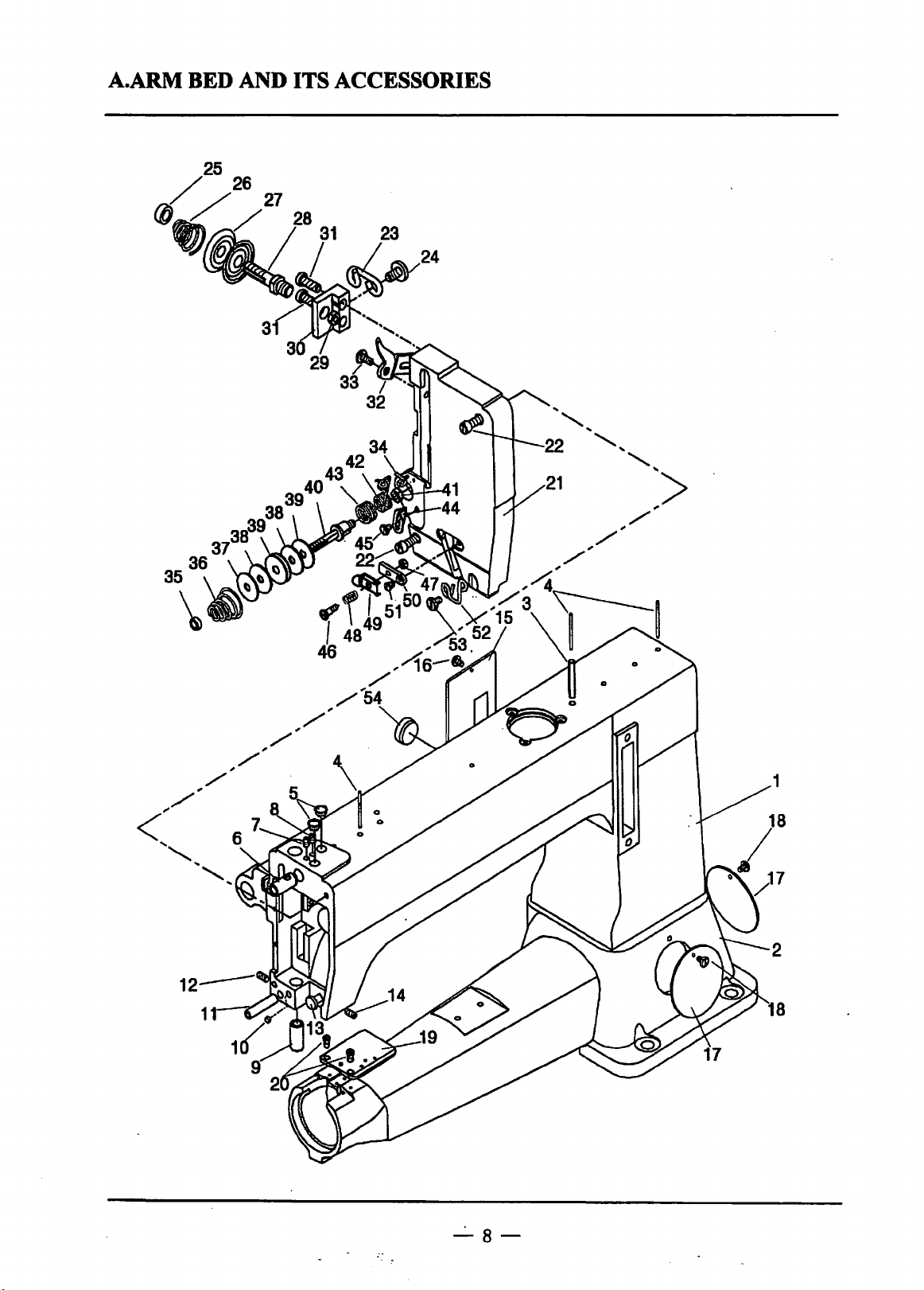
A.ARM BED AND ITS ACCESSORIES
_.
8-
Page 11

A.ARM
BED
AND
ITS
ACCESSORIES
Fig.
No.
A01
A02
A03
A04
AOS
A06
A07
AOS
A09
A10
All
A12
A13
A14
AlS
A16
A17
A18
A19
A20
A21
A22
A23
A24
A25
A26
A27
A28
A29
A30
A31
A32
A33
A34 H7246B8001
A35
A36
A37
A38
A39
A40
A41
A42
A43
Part
No.
H7208B8001
H7210B8001
H7215B8001
H7216B8001
HA307B0674
H7217B8001
HA100C2020
HA100C2020
H7218B8001
HA30SE0662
H7219B8001
HA100C2020
H7220B8001
H2405D0664
H722SB8001
HA100B2060
H7228B8001
HA100B2060
H7235B8001
HA7311C806
H7236B8001
H7238B8001
H7240B8001
H3410C301K
HA115B0702
H7241B8001
HA310B070S
H7242B8001
H2010J0066
H7243B8001
HA11100683
H7244B8001
H7245B8001
HA115B0702
H7241B8001
H7248B8001
H7249B8001
H72SOB8001
H72S1B8001
HA710N0683
H72S3B8001
H72S4B8001
Description
Arm
Bed
Oil pipe
Oil wick
Rubberp1ug
Needle
bar
guide bracket stud bushing
Screw
Screw
Presser
bar
bushing
Screw
Pin
Screw
Mandril
Screw
Arm side cover
Screw
Round
Screw
Worktable for accessories
Screw
Face plate
Screw
Thread guide
Screw
Nut
Tension spring
Tension disc
Tension screw stud
Tension nut
Thread tension regulator complete base
Screw
Tension releasing disc
Screw
Thread guide
Tension nut
Tension spring
Washer
Felt
Damping plate
Tension screw stud
Temsopmnut
Thread take-up spring
Spring
of
needle
cover
bar
guide bracket
Pes.
1
1
1
3
2
1
1
SM1S/6.4(28)x10
1
SM1S/64{28)xlO
1
...
1
SM15/64{28)x4.S
1
1
SM1S/64(28)xlO
1
1
SM1S/64(28)x14
1
1 SM11/64(40)x9
2
2 SM11/64(40)x9
1
2 SM11/64(40)x9
1
2 SM1S/64(28)x22
1
1
SM9/64(40)x6.S
1
1
2
1
1
SM9/32(28)
1
2 SM11164(40)x12
1
1
SM3/16"(28)
1
1
1
2
2
1
1
1
SM1S/64(28)
1
1
.,
Remarks
I
-9-
Page 12

A.ARM
BED
AND
ITS
ACCESSORIES
Fig.
No.
A44 H72SSB8001
A4S
A46
A47·
A48
A49
ASO
A51 HA7311CC06
A52
A53
A54
Part
No.
H3410C301K Screw
H7257B8001
H72~8B8001
H7259B8001
H7260B8001
H7261B8001
H7262B8001
H3410C301K
HA300B2100
Description
Thread
take-up spring guide plate
Screw
Nut
Tension spring
Tension disc
Thread
tension regulator complete base
Screw
Thread
guide
Screw
Rubber plug
Pes.
1
SM9/64(40)x6.5
1
1 SM118(44)
1 SMl/8(44)
1
1
1
1 SM9/64(40)x6
1
1 SM9/64(40)x6.5
1
Remarks
-10-
Page 13

B.NEEDLE BAR AND THREAD TAKE-UP MECHANISM
11
35
36
5
~~b
23
-11-
Page 14

B.NEEDLE
BAR
AND
THREAD
TAKE-UP
MECHANISM
Fig.
No.
BOt
B02
B03
B04
BOS
B06
B07
BOS
B09
B10
Bll
Bl2
B13
B14
B15
B16
B17
B18
B19
B20
B21
B22
B23
B24
B25
B26
B27
B28
B29
B30
B31
B32
B33
B34
B3S
B36
B37
B38
B39
B40
Part
H7204C8001
H7205C8001 Screw
H7206C8001
H7208C8001
HA10800661 Collar
HA105D0662 Screw
H7209C8001
H7210C8001
H403060120
H4933K8001
H602040450
H7211C8001
H7212C8001 Screw
H7213C8001
H7214C8001
H2010J0066
H007013050
H7215C8001
H2010J0066
H7216C8001
H7217C8001
H7218C8001 Screw
H7219C8001 Needle
HA700F2100 Screw
H7220C8001
H7222C8001
H7223C8001
H7224C8001
H722SC8001
H320800676 Screw
HA11100683 Screw
H7226C8001
H415060140 Screw
H7213B8001 Bushing
H240SD0664 Screw
H7214B8001
H7212B8001
H2405D0664 Screw
H7211B8001 Bushing
H2405D0664
No.
Description
Pulley
Screw
Arm
shaft
Thread
thke-up
cam
Needle
bar
connecting base link screw
Screw
Screw
Pin
Thread
take-up lever
Roller
RoUer
pin
Nut
Retaining ring-E type
Needle
bar
connecting link screw
Nut
Needle bar connecting link
Needle bar connecting stud
bar
Needle
Needle
bar
guide bracket
Needle bar guide bracket pin
Oil
wick
Needle
bar
guide bracket plate
Needle
bar
guide bracket plate
Felt
Bushing
Screw
baSe
Pes.
1
SMS/16(24)x22.4
1
SMS/16(24)x21.4
1
1
1
SM114(40)x6
2
1
1
2
0Bff68
2 SM114(40)x10
1
0Bff117
1
1
1
1
1 SM9/32(28)
1
0Bff8965
1
1 SM9/32(28)
1
1
SM1/4(40)x4.5
2
1
1 SM11/64(40)x7
1
DY•3
1
1
1
1
1 SM15/64(28)x10.5
1 SM11164(40)x12
1
1
0Bff70.1
1
1
SM 1 S/64(28)?<
3
1
1 SM15/64(28)X14
1
1
SM
M6x12
4x45
26#
M6x14
15/64{28)x 14
Remarks
14
-12-
Page 15

C.LOWER
SHAFf
MECHANISM
-13-
Page 16

C.LOWER
SHAFf
MECHANISM
Fig.
No.·
COl
C02
C03
C04
cos
C06
C07
cos
C09
ClO
Cll
Cl2
Cl3
Cl4
C15
Cl6
Cl7
Cl8
Cl9
C20
C21
C22
C23
C24
C25
C26
C27
C28
C29
C30
C31
C32
C33
C34
C35
C36
C37
C38
C39
C40
C41
C42
C43
Part
H7204D8001
H7205D8001
H7206D8001
H415060250
H4728H8001 Washer
H7237D8001
H7207D8001
H2000B2050
H7208D8001
H7209D8001
H7210D8001
H7211D8001
H7213D8001
H7214D8001
H7215D8001 Plate
H7216D8001 Screw
H2000M0120
H7218D80Q-l
H7219D8001
H7220D8001
H7222D8001
H415080200
H7223D8001
H7224D8001
H2010J0066
H7226D8001
HA108G0661
H7239D8001
H7227D8001
H602040220
H7228D8001
H7229D8001
H7230D8001
H7231D8001
H7232D8001
H7233D8001
H7234D8001
H7235D8001
H7236D8001
H7234B8001
HA3411D308
HA100C2020
H723o:esoo 1
No.
Description
Eccentric
Screw
pin
Screw
Bearing
Eccentric cover
Screw
Crank connecting rod
Crank connecting rod pin
Pin
Screw
Shuttle shaft
Plate
Nut
Inside Shaft
Oil wick
Rivet
Lower shaft crank
Screw
Shuttle shaft slide block
Screw
Nut
Lower shaft
Collar
Screw
Shuttle driver
Pin
Bobbin
Shuttle race body
Shuttle race back ring
Screw
Spring
Shuttle race cap
Screw
Spring
Screw
Bushing
Screw
Screw
Bushing
Pes.
1
SM15/64(28)Xl2
1
2
GBmO.l
2
2
K43x48Xl7(NTN)
1
1
SM11/64(40)x9
2
1
1
1
1 SM3/16(32)X
1
1
1
2
2
SMll/64(40)
1
1
1
1
GBmO.l
1
1
1
1 SM9/32(28)
1
1
SM114(40)x3.5
2
1
1
OB!f117
1
1
1
2 SM3/16(28)
2
1
2 SM1/8(44)
2
2 SM3/32(56)
1
1 SM15/64(28)x7
1
SM15/64(28)x10
1
M6x25
M8x20
4X22
Remarks
18
-14-
Page 17

C.LOWER
SHAFf
MECHANISM
Fig.
No.
C44
C4S
C46
C47
Part
No.
H2405D0664
H7229B8001
H2405D0664
H7240D7101
Screw
Bushing
Screw
Shuttle hook
Description
Pes.
1
SM15/64(28)xt4
1
1 SM15/64(28)xl4
1
KSP-204N(-itr:Jc)
Remarks
-15-
Page 18

D.FEEDING MECHANISM
11
7
5
6
8
46
"'x•
,.
.......
,..
. >
......
,..
,..,.. 28
·'·
-16-
Page 19

D.FEEDING MECHANISM
Fig.
No.
DOl
002
003
004
DOS
006
007
008
009
DlO
Dll
Dl2
013
D14
D15
016
Dl7
Dl8
019
020
021
022
023
024
025
026
027
028
029
030
031
032
033
034
035
036
037
038
039
D40 H7239D8001
041 H7229E8001
042
043
Part
No.
H7205E8001
H7206E8001
H7207E8001
H2000B2050
H7208E8001
H7209E8001
H2010J0066
H7210E8001
H7211E8001
H415050140
H7212E8001
H7213E8001
HA10400012
H7211D8001
H7214E8001
H7215E8001
H7216E8001
HE00001032
H7217E8001
HF01080320
H003008080
H7218E8001
H415060200
H7219E8001
H007013080
H7220E8001
HA10800661
H7239D8001
H7221E8001
H7222E8001
H7223E8001
H2013N0067
H7225E8001
H7226E8001 Feed dog
HA700F2100 Screw
H7219E8001
H007013080
H7227E8001
H7228E8001
H571108001
H7230E8001
Description
Feed cam
Screw
Feed cam cover
Screw
Feed forked counection
Feed forked counection crank pin
Nut
Stitch
length counecting link
Stitch
length counecting link crank pin
Screw
Stitch
length adjusting pin
Damping plate
Screw
Screw
Stitch length adjusting bolt
Stitch length limited plate
Nut
Metal ball
Spring
ball
Plastic
Nut
Feed driving rock shaft crank
Screw
Feed driving rock shaft
Retaining
Feed driving rock
Collar
Screw
Crank pin
Feed driving counecting link
Feed driving counecting link
Nut
Feed dog base
Feed lifting rock
Retaining ring-E type
Feed lifting rock shaft
Collar
Screw
Feed dog base limited plate
Screw
Needle plate
rin~-E
type
shaft
shaft
crank
pin
crank
crank pin
pin
Pes.
1
2
SM15/64(28)x6
1
2
SM11164(40)x9
1
1
1
SM9/32(28)
1
1
1
OBII70.1 M5x14
1
1
2 SM3/16(28)x12
1 SM3/16(32)xt8
1
1
1
1
OB!f308 3.175
1
1
JBm271.1
1 OB!f6172.1 M8
1
2
OBmO.l
2
2
OB!f8968
1
1
SM1/4(40)x3.5
2
1
1
1
1 SMl/4(24)
1
1
SM11/64(40)x7
1
1
1
OB!f8968
1
1
2 SM1/4(40)x3.5
1
SM11/64(40)x6
2
1
M6x20
Remarks
M8x32
-17-
Page 20

D.FEEDING
MECHANISM
Pig.
No.
D44
D45
D46
047
048
D49 H7231B8001 Bushing
050
051
052
Part
No.
H7231E8001 Screw
H7232E8001
HA104F0654 Screw
H7232B8001 Bushing
HA100C2020 Screw
HA3411D308 Screw
H7233B8001
H240SD0664
Stitch length outside plate
Bushing
Screw
Description
Pes.
2 SM3/16(28)x9.5
1
2 SM15/64(28)x9
1
SM15/64(28)x1o
1
1
1 SM15/64(28)x7
1
SM15/64(28)x 14
1
Remarks
-18-
Page 21

E.PRESSER FOOT MECHANISM
1
~
10
9
-19-
13
Page 22

~
E.PRESSER
FOOT
MECHANISM
Fig.
No.
E01
E02
E03
E04
EOS
E06
E07
E08
E09
E10 HA719B0709
Ell
E12
E13
E14
E1S
E16
E17
E18
E19
E20
E21
E22
Part
No.
H7204F8001
H720SF8001
HA710P0673
H7206F8001
H7207F8001
H7208F8001
H7209F8001
H7210F8001
H7211F8001
H7212F8001
H7213F8001
H7214F8001
H721SF8001
H7217F8001
H7218C8001
HF01080320
H7219F8001
H7220F8001
H7221F8001
H7222F8001
H609030180
Description
Presser foot
Screw
Nut
Finger
guard
Presser bar
Presser bar spring
Thumbscrew
Nut
Walking foot
Screw
Presser bar
Screw
Presser bar lifting
Washer
Collar
Screw
Plastic ball
Bolt
Presser bar guide bracket
Connecting rod
Screw
Pin
shaft
Pes.
1
1 SM9/64(40)x14
1 SM9/64(40)
1
1
1
1 SMS/8(28)
1
1
1 SM11/64(40)x7
1
1
1
1
1
2 SM1/4(40)x4.S
1
mm211.1
1
1
1
1 SM1/4(40)x40
1
0Bff879.1 3x18
Remarks
M6x2o
-20-
Page 23

F. UPPER FEED LIFTING
ROCK
SHAFT MECHANISM
14
-21-
Page 24

-F.UPPER
FEED
LIFTING
ROCK
SHAFf
MECHANISM
Fig.
No.
FOl
H720408001
F02
HA307C0066 Screw
F03
H720508001
F04
H720608001 Screw
FOS
H720708001 Washer
F06
H720808001
F07
H720908001
F08
H721008001
F09
H721108001
FlO
H7212G8001
Fll
Fl2
H721308001
Fl3
H721408001
Fl4
FlS
H721508001
Fl6
H721408001
Fl7
H721608001
Fl8
HA10400012
F19
H721708001
F20
H722108001
F21 H721808001
F22
H721908001
F23
HA700B2060
H722008001
F24
F25
H7221B8001
F26
HA3411D308 Screw
F27
H7222B8001
HA3411D308
F28
,··
Part
No.
H415060140
H007013080
Description
Presser foot lifting eccentric
Eccentric
Nut
Adjusting crank
Screw
Presser foot lifting
Presser foot lifting shaft crank
Screw
Presser
Screw
Retaining
Presser foot lifting lever
Screw
Presser foot lifting lever base
Screw
RoUer
Bearing
Screw
RoUer
Screw
Walking
Bushing
Bushing
Screw
connecting link
shaft
foot lifting connecting link
ring-E type
base plate
foot lifting connecting link
Pes.
1
2 SM1/4(40)x6
1
1
1
SMll/32(28)
1
1
1 SMS/16(18)
1
1
OBmO.l
1
1
2
4 OBfT896 8
1
2
1
SM3/16(28)xl2
2
1
ISOK7
1
1
SMl
1
SM3/16(32)x8
2
1
1
SMl
1
1
1 SM15/64(28)x7
M6xt4
5/64(28)
5/64(28)x7
Remarks
-22-
Page 25

G.NEEDLE BAR ROCKING MOTION MECHANISM
9
17
-23-
Page 26

G.NEEDLE
BAR
ROCKING
MOTION
MECHANISM
Fig.
No.
G01
G02
G03
G04
G05
G06
G07
G08
G09
G10
Gll
Gl2
Gl3
Gl4
Gl5
Gl6
G17
G18
Gl9
G20
G21
G22
Part
No.
H7204H8001
H7219E8001
H007013080 Retaining ring-E type
H7206H8001
H7207H8001
H7208H8001
H7210G8001
H7209H8001
H7210H8001
HA105D0662
H7211H8001
H7218C8001
HA100C2070 Screw
H7212H8001
H7214G8001
H007013080 Retaining ring-E type
H7213H8001
H7214H8001
H7224B8001
HA3411D308
H7223B8001
HA3411D308
Needle bar rocking connecting link
Screw
Adjusting
Adjusting
Screw
Screw
Needle bar rock shaft
Collar
Screw
Needle bar rocking crank 1
Screw
Needle bar rocking connecting link
Screw
Screw base
Screw
Bushing
Screw
Bushing
Screw
crank
crank
base
Description
Pes.
1
1
1
GB!f896 8
1
1
1
1
1
2
4 SMl/4(40)x4.5
SMl/4(40)x4.5
1
SM9/32(28)x
1
1
2
GB/f896 8
2
1
SM1l/64(40)x4.5
3
1
SM15/64(28)x7
1
1
SM
1
15/64(28)x7
'
Remarks
14
-24-
Page 27

H.KNEE
LIFI'ER
MECHANISM
-25-
Page 28

H.KNEE
LIFTER
MECHANISM
Pig.
No.
HOI
H02
H03
H04
HOS
H06
H07
H08
H09
H10
Hll
H12
H13
H14
Part
H720418001
H720518001
H720618001
HA300J2280 Screw
H720718001
H720818001
H720518001
H720918001
H721018001
H721118001
H721218001
H721418001
HA300J2280
H721318001
No.
Knee lifter lever
Screw
Knee lifter lever base
Screw
Knee lifter rod
Screw
Coil spring
Screw
Screw
Washer
Knee
lifter lever connecting plate
Screw
Screw
Description
Pes.
2
SM15/64(28)x6
1
1
2
SM
1 5/64(28)x6.5
SM
1
1
2
1
1
1 SM15/64(28)xt3
1
1
2 SMl 5/64(28)x6.5
1
1 5/64(28)x8
SM15/64(28)x6
SM1/4(40)x3.5
Remarks
-26-
Page 29

I.BOBBIN WINDER MECHANISM
15
10
11
~33
____./ 34
~'
-\j 6 I
35
22.~,
8
~
19
(~
5
9
12
-27-
Page 30

I.BOBBIN
WINDER
MECHANISM
Fig.
No.
101
102
103
104
lOS
106
107
108
109
110
Ill
112
113
114
us
116
117
118
119
120
121
122
123
124
I2S
126
127
128
129
130
131
132
133
134
135
Part
No.
H6706N8001
H6707N8001
H6708N8001
H7210J8001
H7213J8001
H6713N8001
H6714N8001
H671SN8001
H0070130SO
1f720SJ8001
H6717N8001
H7214J8001
H66S8B8001
H6720N8001
HA100H21SO
H720618001
H3200B2100
H6722N8001
H6723N8001
H6731N8001
H431030040
H6724N8001
H672SN8001
H700SD8001
H4723D8001
H310700662
H7208J8001
HA310B070S
HA11SB0702
HA11SB7010
H3300B2040
H6662B8001
H003008040
H67S6B8001
HASOOC2070
Description
Bobbin winder plate
Pin
Pin
Bobbin winder
Bobbin winder
Bushing
Pin
Bobbin winder spring
Retaining ring-E type
Bobbin winder shaft
Bobbin
Driwnwheel
Friction rubber band
Bobbin winder lever
Screw
Winding length limited plate
Screw
Washer
Pin
Screw
Screw
Spring
Bobbin winder cam
Driving wheel
Screw
Screw
Screw
Tension
Nut
Limited plate
Spring
Thread
Washer
Blade
Screw
base
diso
guide
crank
crank
shaft
Pes.
1
1
1
1
1
2
1
1
2 0Bfl'896 S
1
1
1
1
1
1 SM9/64( 40)x
1
1
1
1
MSX6
1
2
HRC34-48
1
1
1
SM1S/64(28)x4.S
2
3 SM11/64(40)x8
1
2
1
1
1
1
2
0Btr6172.1
1
2 SM9/64(40)xS
Remarks
11
-*iiiftHt~!l
M4
-28-
Page 31

J.ACCESSORIES
~<'(
I
10
1{
12
20·
13
1~
21
27
(
29
Page 32

J.ACCESSORIES
Fig.
No.
J01
J02
J03
104
J05 H7209K8001
J06
J07
J08
J09
110
Jll
Jl2
113
J14
115
116 HJ02090110
117
Jl8
J19
J20 HA200J2030
J21
J22
J23
J24
J2S
J26
J27
J28
Part
No.
H7207K8001 Silicon oil box
H7208K8001
H605030400
H34411C410 Screw
H3215K0693 Screw
H7210K8001
H7211K8001
HA800F2020
HB00001050
HB00001040
HB00001030
HA300J2070
HA300J2200
HA300J2210
HJ02100130
H7228D8001
H7220C8001 Needle
H200400069
H7212K8001 Head cover
H103100700
H003002100 Nut
H005001100
HP0100E202
H7235K8001
Description
Cover
Pin
Spring
Thread
guide
Nut
Screw
Hexagon
Hexagon socket screw
Hexagon socket screw key
Screw
Screw
Screw
Spanner
Spanner
Bobbin
Thread
Oiler
Screw
Washer
Hook
Hook
Chain
socket screw key
driver (size L)
driver (size
driver (size S)
stand assy
M)
key
Pes.
1
1
1
OB/fl19.23x40
1 SM9/64(40)x4
1
1 SM9/64(40)x5
2
2 SM3/32(56)
1 SM15/64(28)x13.5
OB/1'53565
1
1
OB/1'53564
OB/1'53563
1
1
1
1
1 OB/1'4388 9x11
OB/1'4388 10x13
1
4
4
DY*3 26#
1
1
Jl~M
1
JU\tZ.M
4 OB/1'5782 MIOx70
4
OB/1'6170 M10
8
OB/1'97.1 10
1
1
1100mm
1
Remarks
-30-
Page 33

SHANGHAI HUIGONG
N0.3
SEWING MACIDNE FACTORY
ADD: 1418, Yishan Road, Shanghai, China
Zip
Code: 201103
Overseas Business: TEL: 86-21-64853303 FAX: 86-21-64854304
E-mall:highlead@online.sh.cn http://www.highlead.com.cn
The description
covered
In
tlda
manual
Is
subject
to
change
lor
Improvement
ol
the
commodity without notice
2004.2.
Printed
 Loading...