

HF-LPT130A
Low Power WiFi Module User Manual
Overview of Characteristic
V 1.3
Support IEEE802.11b/g/n Wireless Standards
Based on Cortex-M4 SOC, 160MHz CPU, 352KB RAM for 1MB Flash Version, 448KB RAM
for 4MB Flash Version
Support UART Data Communication Interface
Support Work As STA/AP/AP+STA Mode
Support Smart Link Function (APP program provide)
Support WeChat Airkiss 2.0
Support Wireless and Remote Firmware Upgrade Function
Support Antenna
HF-LPT130A
Single +3.3V Power Supply
monopole antenna
Small Size:
HF-LPT130A
FCC/CE/SRRC/RoHS Certificated
High-Flying Electronics Technology Co., Ltd(www.hi-flying.com)
22mm x 14.3mm x 8mm, DIP10 package
- 1 -

HF-LPT130A Low Power WiFi Module User Manual
TABLE OF CONTENTS
LIST OF FIGURES ................................................................................................................................... 4
LIST OF TABLES .................................................................................................................................... 5
HISTORY .................................................................................................................................................. 6
1. PRODUCT OVE RVIEW ................................................................................................................ 7
1.1. General Description ................................................................................................................. 7
1.1.1 Key Application ................................................................................................................... 7
1.1.2 Device Paremeters ............................................................................................................. 8
1.2. Hardware Introduction ............................................................................................................. 9
1.2.1. HF-LPT130A Pins Definition ............................................................................................... 9
1.2.2. Electrical Characteristics ..................................................................................................10
1.2.3. HF-LPT130A Mechanical Size..........................................................................................11
1.2.4. HF-LPT130A On-board Chip Antenna ..............................................................................11
1.2.5. External Antenna ..............................................................................................................12
1.2.6. Evaluation Kit ....................................................................................................................12
1.2.7. Hardware Typical Application ...........................................................................................14
2. FUNCTION AL DESCRIPTION ..................................................................................................16
2.1. Wireless Networking ..............................................................................................................16
2.1.1. Basic Wireless Network Based On AP .............................................................................16
2.1.2. Wireless Network Based On STA .....................................................................................16
2.2. Work Mode : Transparent Transmission Mode ...................................................................17
2.3. Encryption ..............................................................................................................................17
2.4. Parameters Configuration .....................................................................................................17
2.5. Firmware Update ....................................................................................................................18
2.6. SOCKET B Function ..............................................................................................................18
2.7. Multi-TCP Link Connection ...................................................................................................18
3. OPER ATION GUID ELINE ..........................................................................................................20
3.1. Configuration ..........................................................................................................................20
3.1.1. Open Web Management Interface ...................................................................................20
3.1.2. System Page.....................................................................................................................21
3.1.3. Work Mode Page ..............................................................................................................22
3.1.4. STA Setting Page .............................................................................................................22
3.1.5. AP Setting Page ...............................................................................................................24
3.1.6. Other Setting Page ...........................................................................................................24
3.1.7. Account Management Page .............................................................................................25
3.1.8. Upgrade Software Page ...................................................................................................25
3.1.9. Restart Page .....................................................................................................................25
3.1.10. Restore Page ................................................................................................................26
3.1.11. Internal Webpage ..........................................................................................................26
High-Flying Electronics Technology Co., Ltd(www.hi-flying.com)
- 2 -

HF-LPT130A Low Power WiFi Module User Manual
3.2. Usage Introduction ................................................................................................................27
3.2.1. Software Debug Tools ......................................................................................................27
3.2.2. Network Connection .........................................................................................................27
3.2.3. Default Parameter Setting ................................................................................................27
3.2.4. Module Debug...................................................................................................................28
3.3. Typical Application Examples ..............................................................................................29
3.3.1. Wireless Control Application .............................................................................................29
3.3.2. Remote Management Application.....................................................................................30
3.3.3. Transparent Serial Port Application ..................................................................................30
High-Flying Electronics Technology Co., Ltd(www.hi-flying.com)
- 3 -

HF-LPT130A Low Power WiFi Module User Manual
LIST OF FIGURES
Figure 1. HF-LPT130A Pins Map .......................................................................................................... 9
Figure 2. HF-LPT130A Mechanical Dimension ...................................................................................11
Figure 3. HF-LPT130A suggested Module Placement Region ...........................................................12
Figure 4. HF-LPT230 EVK ...................................................................................................................13
Figure 5. HF-LPT130A EVK ................................................................................................................13
Figure 6. HF-LPT130A Order InformationTypical Application .............................................................14
Figure 7. HF-LPT130A Hardware Typical Application .........................................................................15
Figure 8. HF-LPT130A Basic Wireless Network Structure ..................................................................16
Figure 9. HF-LPT130A STA Network Structure...................................................................................16
Figure 10. Socket B function demo ....................................................................................................18
Figure 11. Multi-TCP Link Data Transmition Structure ......................................................................19
Figure 12. Open Web Management page ..........................................................................................20
Figure 13. 1MB Flash Version webpage ............................................................................................21
Figure 14. System Web Page ............................................................................................................21
Figure 15. Work Mode Page ..............................................................................................................22
Figure 16. STA Setting Page .............................................................................................................23
Figure 17. STA Scan Page ................................................................................................................23
Figure 18. AP Setting Page ...............................................................................................................24
Figure 19. Other Setting Page ...........................................................................................................25
Figure 20. Account Page....................................................................................................................25
Figure 21. Upgrade SW page ............................................................................................................25
Figure 22. Restart Page .....................................................................................................................26
Figure 23. Restore Page ....................................................................................................................26
Figure 24. Internal Webpage .............................................................................................................27
Figure 25. STA Interface Debug Connection .....................................................................................27
Figure 26. AP Interface Debug Connection .......................................................................................27
Figure 27. “CommTools” Serial Debug Tools ....................................................................................28
Figure 28. “TCPUDPDbg” Tools Create Connection .........................................................................28
Figure 29. “TCPUDPDbg” Tools Setting ............................................................................................29
Figure 30. “TCPUDPDbg” Tools Connection .....................................................................................29
Figure 31. Wireless Control Application .............................................................................................29
Figure 32. Remote Management Application.....................................................................................30
Figure 33. Transparent Serial Port Application ..................................................................................30
High-Flying Electronics Technology Co., Ltd(www.hi-flying.com)
- 4 -

HF-LPT130A Low Power WiFi Module User Manual
LIST OF TABLES
HF-LPT130A Module Technical Specifications ...................................................................... 8 Table1.
HF-LPT130A Pins Definition .................................................................................................. 9 Table2.
Absolute Maximum Ratings: .................................................................................................10 Table3.
Power Supply & Power Consumption: .................................................................................11 Table4.
HF-LPT130A External Antenna Parameters ........................................................................12 Table5.
HF-LPT130A Evaluation Kit Interface Description ...............................................................13 Table6.
HF-LPT130A Web Access Default Setting ...........................................................................20 Table7.
High-Flying Electronics Technology Co., Ltd(www.hi-flying.com)
- 5 -

HF-LPT130A Low Power WiFi Module User Manual
HISTORY
Ed. V0.2 07-25-2017 Internal Version.
Ed. V0.2 08-22-2017 Release Version
Ed. V1.1 13-10-2017 Add HF-LPT130A type module
Ed. V1.2 10-11-2017 Add HF-LPB130 type module
Ed. V1.3 03-01-2018 Update HF-LPT230 Pin,webpage config.
High-Flying Electronics Technology Co., Ltd(www.hi-flying.com)
- 6 -

HF-LPT130A Low Power WiFi Module User Manual
1. PRODUCT OVERVIEW
1.1. General Description
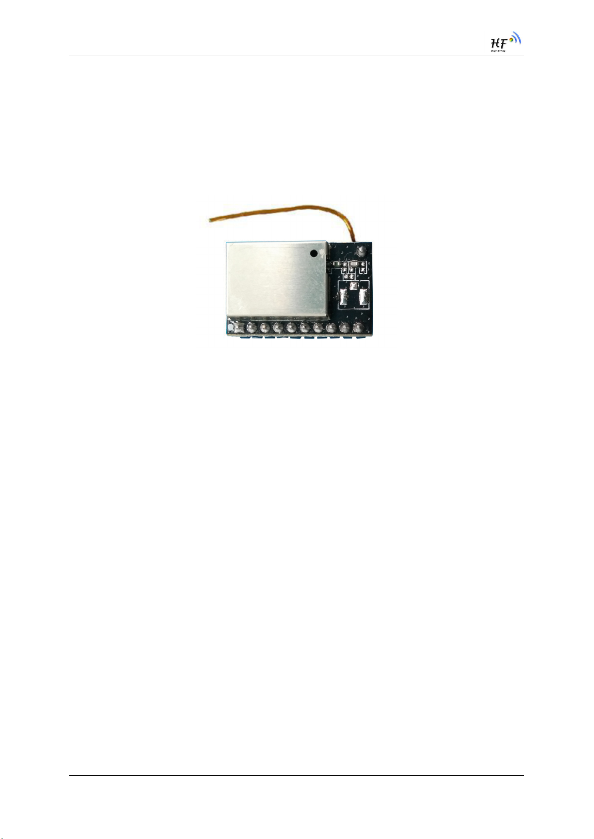
The HF-LPT130A is a fully self-contained small form-factor, single stream, 802.11b/g/n Wi-Fi module,
which provide a wireless interface to any equipment with a Serial interface for data transfer.HF-
LPT130A integrate MAC, baseband processor, RF transceiver with power amplifier in hardware and
all Wi-Fi protocol and configuration functionality and networking stack, in embedded firmware to make
a fully self-contained 802.11b/g/n Wi-Fi solution for a variety of applications.
The HF-LPT130A employs the world's lowest power consumption embedded architecture. It has been
optimized for all kinds of client applications in the home automation, smart grid, handheld device,
personal medical application and industrial control that have lower data rates, and transmit or receive
data on an infrequent basis.
1.1.1 Key Application
Remote equipment monitoring
Asset tracking and telemetry
Security
Industrial sensors and controls
Home automation
Medical devices
High-Flying Electronics Technology Co., Ltd(www.hi-flying.com)
- 7 -
HF-LPT130A Low Power WiFi Module User Manual
1.1.2 Device Paremeters
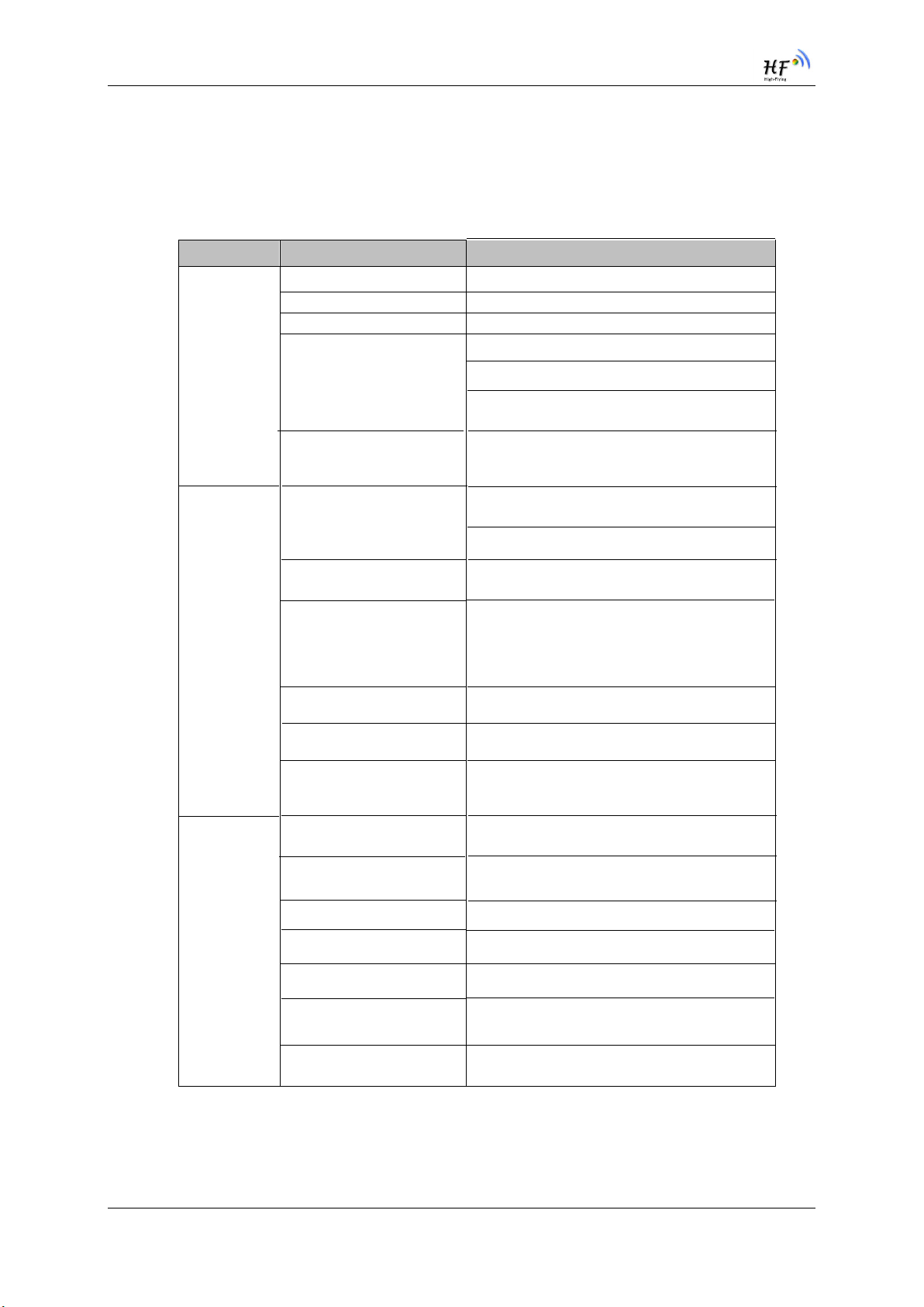
HF-LPT130A Module Technical Specifications Table1.
Class Item Parameters
Certification FCC/CE/SRRC/RoHS
Wireless standard 802.11 b/g/n
Frequency range 2.412GHz-2.462GHz
RF Power
Wireless
Parameters
Antenna
802.11b: 20.5dBm (@1Mbps)
802.11g: 22.0dBm (@6Mbps)
802.11n: 21.5dBm (@HT20, MCS0)
monopole antenna
Hardware
Parameters
Data Interface
Operating Voltage
Operating Current
Operating Temp.
Storage Temp.
Dimensions and Size
Network Type STA/AP/AP+STA
Security Mechanisms WEP/WPA-PSK/WPA2-PSK
Encryption
Update Firmware
UART
GPIO,SPI
2.9~3.6V
Peak (Continuous TX): 260Ma
Average(STA, No data): 27mA
Average(STA, Continuous TX): 35mA
Average(AP): 80mA
-25℃- 85℃
-40℃- 125℃
22mm(L) × 14.3mm(W) × 8mm(H)
WEP64/WEP128/TKIP/AES
Local Wireless, Remote OTA
Software
Parameters
High-Flying Electronics Technology Co., Ltd(www.hi-flying.com)
Customization
Network Protocol
User Configuration
Support SDK for application develop
IPv4, TCP/UDP/HTTP/TLS(SDK)
AT+instruction set. Android/ iOS
Smart Link APP tools
- 8 -
HF-LPT130A Low Power WiFi Module User Manual
Pin
Describtion
Net Name
Signal
Type
Comments
1
Ground
GND
Power
2
+3.3V Power
DVDD
Power
3
Multi-Function
nReload
I,PU
4
Module Reset
EXT_RESETn
I,PU
5
UART0
UART0_RX
I
6
UART0
UART0_TX
O,PU
7
GPIO25
GPIO25
I/O
GPIO25,PWM3
8
GPIO24
GPIO24
I/O
GPIO24,PWM2
9
Module Boot Up
Indicator
nReady
10
Wi-Fi Status
nLink O “0” – Wi-Fi connect to router
1.2. Hardware Introduction
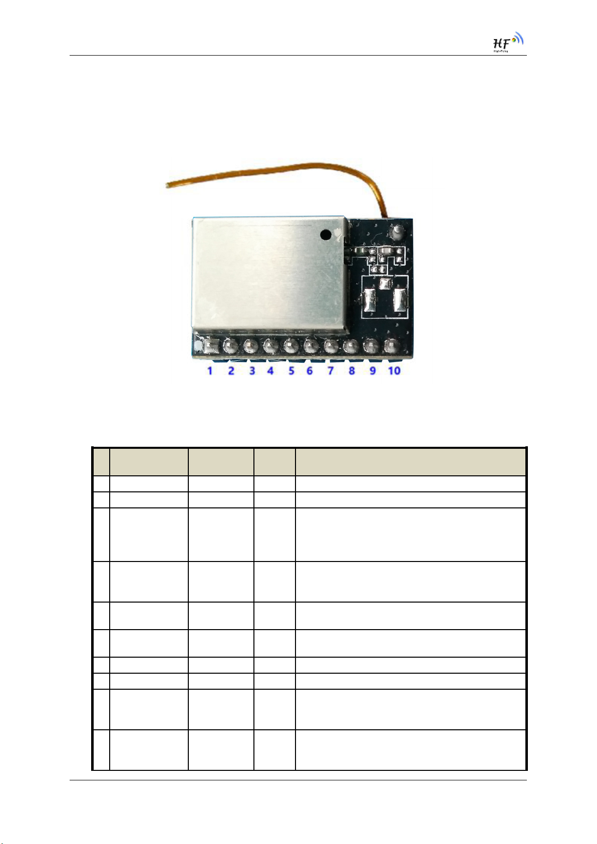
1.2.1. HF-LPT130A Pins Definition
Figure 1. HF-LPT130A Pins Map
HF-LPT130A Pins Definition Table2.
Detailed functions see <Notes>
There will be 2ms output low when bootup, after
then it works as input pull high.
“Low” effective reset input. There is RC reset
circuit internally. External pull-up resistor is not
3.3V UART0 Communication Input
GPIO3, PWM4
allowed.
GPIO1
High-Flying Electronics Technology Co., Ltd(www.hi-flying.com)
O “0” – Boot-up OK;
“1” – Boot-up No OK;
GPIO23, PWM1
“1” – Wi-Fi unconncted;
Detailed functions see <Notes>
- 9 -
HF-LPT130A Low Power WiFi Module User Manual
Pin
Describtion
Net Name
Signal
Type
Comments
GPIO22,PWM0
Parameter
Min.
Typ.
Max.
Unit
Storage temperature range
-40
125
°C
Maximum soldering temperature
IPC/JEDEC J-STD-020
260
° C
<Notes>
I — InputO — Output
PU—Internal Resistor Pull Up
Supply nReload Pin (Button) function
1. When this pin is set to “low” during module boot up, the module will enter wireless
firmware and config upgrade mode. This mode is used for customer manufacture.
(See Appendix to download software tools for customer batch configuration and
upgrade firmware during mass production)
After module is powered up, short press this button ( “Low” < 2s ) and loose to make
2.
the module go into “Smart Link “ config mode, waiting for APP to set password and
other information. (See Appendix to download SmartLink APP)
3. After module is powered up, long press this button ( “Low” > 4s ) and loose to make
the module recover to factory setting.
High-Flying strongly suggest customer fan out this pin to connector or button for
“Manufacture” and “ Smart Link” application.
I/O: Digital I/O Power—Power
nReady Pin (LED) function(Low effective)
1. OS initial finished indicator. Only after this pin output low, can the UART function be
used.
nLink Pin (LED) function(Low effective)
1. At wireless firmware and config upgrade mode , this LED used to indicate configure
and upgrade status.
2. At “Smart Link “ config mode, this LED used to indicate APP to finish setting.
3. At normal mode, it’s Wi-Fi link status indicator
High-Flying strongly suggest customer fan out this pin to LED.
PWM function
PWM0~PWM3 support 1
~4s period.
5us
UART1 Debug
1. Is used for debug log or firmware program.
2. Can be used for communication in SDK.
~100% duty, 5us~256speriod, PWM4 support 1~100% duty,
1.2.2. Electrical Characteristics
High-Flying Electronics Technology Co., Ltd(www.hi-flying.com)
Absolute Maximum Ratings: Table3.
Condition
- 10 -

HF-LPT130A Low Power WiFi Module User Manual
Supply voltage
0
3.6 V Voltage on any I/O pin
0
3.6
V
ESD (Human Body Model HBM)
TAMB=25°C
2.5
KV
ESD (MM)
TAMB=25°C
0.25
KV
Parameter
Condition
Min.
Typ.
Max.
Unit
Operating Supply voltage
2.9
3.3
3.6 V Supply current, peak
Continuous Tx
260
mA
Supply current,
STA No data transfer
27
mA
Supply current,
STA Continuous data
transfer
35
mA
Supply current,
80
mA
Power Supply & Power Consumption: Table4.
AP
1.2.3. HF-LPT130A Mechanical Size
HF-LPT130A modules physical size Unit: mm as follows:
1.2.4. HF-LPT130A On-board Chip Antenna
HF-LPT130A module support internal copper line antenna option. When customer select internal
antenna, you shall comply with following antenna design rules and module location suggestions:
For customer PCB, RED color region (copper line antenna area) can’t put componet or paste
GND net;
Antenna must away from metal or high components at least 10mm;
High-Flying Electronics Technology Co., Ltd(www.hi-flying.com)
Figure 2. HF-LPT130A Mechanical Dimension
- 11 -

HF-LPT130A Low Power WiFi Module User Manual
Antenna can’t be shieldedby any meal enclosure; All cover, include plastic, shall away from
antenna at least 10mm;
High-Flying suggest HF-LPT130A module better locate in following region at customer board, which to
reduce the effect to antenna and wireless signal, and better consult High-Flying technical people when
you structure your module placement and PCB layout.
Figure 3. HF-LPT130A suggested Module Placement Region
1.2.5. Evaluation Kit
High-Flying provides the evaluation kit to promote user to familiar the product and develop the detailed
application. The evaluation kit shown as below, user can connect to HF-LPT130A series module with
High-Flying Electronics Technology Co., Ltd(www.hi-flying.com)
- 12 -

HF-LPT130A Low Power WiFi Module User Manual
the RS-232 UART, USB (Internal USB to UART convetor) or Wireless interface to configure the
parameters, manage the module or do the some functional tests.
Figure 4. HF-LPT230 EVK
Figure 5. HF-LPT130A EVK
Notes: User need download USB to UART port driver from High-Flying web or contact with technical
support people for more detail.
The external interface description for evaluation kit as follows:
HF-LPT130A Evaluation Kit Interface Description Table6.
Function
External
Interface
LED
High-Flying Electronics Technology Co., Ltd(www.hi-flying.com)
Name Description
RS232 Main data/command RS-232 interface
USB USB to UART interface
DC5V DC jack for power in, 5V input.
Power Power LED
Ready nReady LED
Link nLink LED
- 13 -

HF-LPT130A Low Power WiFi Module User Manual
1.2.7. Har
Button
nReload
dware Typical Application
User Device
Restore factory default configuration after push this
pin more than 4s.
See 1.2.1
High-Flying Electronics Technology Co., Ltd(www.hi-flying.com)
- 14 -

HF-LPT130A Low Power WiFi Module User Manual
Figure 7. HF-LPT130A Hardware Typical Application
Notes:
nReset- Module hardware reset signal. Input. Logics “0” effective.
There is pull-up resister internal and no external pull-up required. When module power up or some
issue happened, MCU need assert nRST signal “0” at least 10ms, then set” 1” to keep module fully
reset.
nLink- Module WIFI connection status indication. Output.
(This pin is recommend to connect to LED, indicate status when the module in wireless
upgrade mode)
When module connects to AP (AP associated), this pin will output “0”. This signal used to judge if
module already at WiFi connection status. Thers is pull-up resister internal and no external pull-up
required. If nLink function not required, can leave this pin open.
nReady- Module boot up ready signal. Output. Logics “0” effective.
The module will output “0” after normal boot up. This signal used to judge if module finish boot up and
ready for application or working at normal mode. If nReady function not required, can leave this pin
open.
nReload- Module restore to factory default configuration.Input. Logics “0” effective.
(This pin is recommend to connect to button, is used to enter wireless upgrade mode)
User can de-assert nReload signal “0” more than 4s through button or MCU pin, then release, module
will restore to factory default configuration and re-start boot up process.. If nReload function not
required, can leave this pin open.
UART0_TXD/RXD- UART port data transmit and receive signal.
High-Flying Electronics Technology Co., Ltd(www.hi-flying.com)
- 15 -

HF-LPT130A Low Power WiFi Module User Manual
2. FUNCTIONAL DESCRIPTION
2.1. Wireless Networking
HF-LPT130A module can be configured as both wireless STA and AP base on network type. Logically
there are two interfaces in HF-LPT130A. One is for STA, and another is for AP. When HF-LPT130A
works as AP, other STA equipments are able to connect to HF-LPT130A module directly. Wireless
Networking with HF-LPT130A is very flexible.
Notes:
AP: that is the wireless Access Point, the founder of a wireless network and the centre of the network
nodes. The wireless router we use at home or in office may be an AP.
STA: short for Station, each terminal connects to a wireless network (such as laptops, PDA and other
networking devices) can be called with a STA device.
2.1.1. Basic Wireless Network Based On AP
Infrastructure: it’s also called basic network. It built by AP and many STAs which join in.
The characters of network of this type are that AP is the centre, and all communication between STAs
is transmitted through the AP. The figure following shows such type of networking.
Figure 8. HF-LPT130A Basic Wireless Network Structure
2.1.2. Wireless Network Based On STA
HF-LPT130A module support STA network mode.
Router
Serial service
server
Figure 9. HF-LPT130A STA Network Structure
High-Flying Electronics Technology Co., Ltd(www.hi-flying.com)
- 16 -

HF-LPT130A Low Power WiFi Module User Manual
2.2. Work Mode : Transparent Transmission Mode
HF-LPT130A module support serial interface transparent transmission mode. The benefit of this mode
is achieves a plug and play serial data port, and reduces user complexity furthest. In this mode, user
should only configure the necessary parameters. After power on, module can automatically connect to
the default wireless network and server.
As in this mode, the module's serial port always work in the transparent transmission mode, so users
only need to think of it as a virtual serial cable, and send and receive data as using a simple serial. In
other words, the serial cable of users’ original serial devices is directly replaced with the module; user
devices can be easy for wireless data transmission without any changes.
The transparent transmission mode can fully compatible with user’s original software platform and
reduce the software development effort for integrate wireless data transmission.
The parameters which need to configure include:
Wireless Network Parameters
Wireless Network NameSSID
Security Mode
Encryption Key
TCP/UDP Linking Parameters
Protocol Type
Link TypeServer or Client
Target Port ID Number
Target Port IP Address
Serial Port Parameters
Baud Rate
Data Bit
Parity (Check) Bit
Stop Bit
Hardware Flow Control
2.3. Encryption
Encryption is a method of scrambling a message that makes it unreadable to unwanted parties,
adding a degree of secure communications. There are different protocols for providing encryption, and
the HF-LPT130A module supports following:
WEP
WPA-PSK/TKIP
WPA-PSK/AES
WPA2-PSK/TKIP
WPA2-PSK/AES
2.4. Parameters Configuration
HF-LPT130A module supports two methods to configuration parameters: AT+instruction set.
High-Flying Electronics Technology Co., Ltd(www.hi-flying.com)
- 17 -

HF-LPT130A Low Power WiFi Module User Manual
AT+instruction set configuration means user configure parameters through serial interface command.
Refer to “AT+instruction set” chapter for more detail.
2.5. Firmware Update
HF-LPT130A module supports multiple upgrade methods:
UART upgrade
Local Network upgrade
2.6. SOCKET B Function
HF-LPT130A support double socket communication, the socket B function is disabled by default.
Figure 10. Socket B function demo
2.7. Multi-TCP Link Connection
When HF-LPT130A module SOCK A configured as TCP Server, it supports Multi-TCP link connection,
and maximum 5 TCP clients permitted to connect to HF-LPT130A module. User can realize multi-TCP
link connection at each work mode.
Multi-TCP link connection will work as following structure:
Upstream: All dates from different TCP connection or client will be transmitted to the serial port as a
sequence.
Downstream: All data from serial port (user) will be replicate and broadcast to every TCP connection
or client.
Detailed multi-TCP link data transmission structure as following figure:
High-Flying Electronics Technology Co., Ltd(www.hi-flying.com)
- 18 -

HF-LPT130A Low Power WiFi Module User Manual
Device 1#
User Device
Device 2#
Device 3#
Figure 11. Multi-TCP Link Data Transmition Structure
High-Flying Electronics Technology Co., Ltd(www.hi-flying.com)
- 19 -

HF-LPT130A Low Power WiFi Module User Manual
Parameters
SSID
IP Address
Subnet Mask
Account
Password
3. OPERATION GUIDELINE
3.1. Configuration
When first use HF-LPT130A series modules, user may need some configuration. User can connect to
HF-LPT130A module’s wireless interface with following default setting information and configure the
module through laptop.
HF-LPT130A Web Access Default Setting Table7.
Default Setting
HF-LPB130
HF-LPT230
HF-LPT130A
10.10.100.254
255.255.255.0
admin
admin
3.1.1. Open Web Management Interface
There is internal webpage and external webpage in modules. The external webpage is for web
management. The internal webpage is only for upgrading. 1MB Flash external webpage is different
from 4MB Flash version, but the internal webpage is the same.
Step 1: Connect laptop to SSID “HF-LPT230” of HF-LPT230 module via wireless LAN card;
Step 2: After wireless connection OK. Open Wen browser and access “http://10.10.100.254”;
Step 3: Then input user name and password in the page as following and click “OK” button.
Figure 12. Open Web Management page
The 1MB Flash version has the simple config page while the 4MB Flash version has the full config
page. 1MB Flash version webpage is as following(By default is Chinese language, upgrade via
internal webpage to upgrade English language).
High-Flying Electronics Technology Co., Ltd(www.hi-flying.com)
- 20 -

HF-LPT130A Low Power WiFi Module User Manual
Figure 13. 1MB Flash Version webpage
The HF-LPT130A web management page support English and Chinese language. User can select
language environment at the top right corner and click “Apply” button.
The main menu include nine pages: “System”, “Work Mode”, “STA Setting”, “AP Setting”, “Other
Setting”, “Account”, “Upgrade SW”, “Restart”, “Restore”.
3.1.2. System Page
At this page, user can check current device’s important information and status such as: device ID
(MID), software version, wireless work mode and related Wi-Fi parameters.
Figure 14. System Web Page
High-Flying Electronics Technology Co., Ltd(www.hi-flying.com)
- 21 -

HF-LPT130A Low Power WiFi Module User Manual
3.1.3. Work Mode Page
HF-LPT130A module can works at AP mode to simplify user’s configuration, can also works at STA to
connect remote server through AP router.
Figure 15. Work Mode Page
3.1.4. STA Setting Page
User can push “Scan” button to auto search Wi-Fi AP router nearby, and can connect with associate
AP through some settings. Please note the encryption information input here must be fully same with
Wi-Fi AP router’s configration, and then it can link with AP correctly.
High-Flying Electronics Technology Co., Ltd(www.hi-flying.com)
- 22 -

HF-LPT130A Low Power WiFi Module User Manual
Figure 16. STA Setting Page
Figure 17. STA Scan Page
High-Flying Electronics Technology Co., Ltd(www.hi-flying.com)
- 23 -

HF-LPT130A Low Power WiFi Module User Manual
3.1.5. AP Setting Page
When user select module works at AP and AP+STA mode, then need setting this page and provide
wireless and network parameters. Most of the system support DHCP to achieve IP address, so we
suggest to “Enable” DHCP server in most applications.
Figure 18. AP Setting Page
3.1.6. Other Setting Page
HF-LPT130A usually works at data transparent transmission mode. At this mode, the user device
which connected with HF-LPT130A will connect and communicate with remote PC or server. At this
page, user need setting serial port communication parameters and defines TCP related protocal
parameters.
High-Flying Electronics Technology Co., Ltd(www.hi-flying.com)
- 24 -

HF-LPT130A Low Power WiFi Module User Manual
Figure 19. Other Setting Page
3.1.7. Account Management Page
This page set web server’s user name and password.
Figure 20. Account Page
3.1.8. Upgrade Software Page
User can upgrade new software (firmware) version through Wi-Fi. After upgrade success, need reboot
it manually before new firmware valid.
Figure 21. Upgrade SW page
3.1.9. Restart Page
Most of the settting and configuration can only effective after system restart. User shall restart after
finish all setting.
High-Flying Electronics Technology Co., Ltd(www.hi-flying.com)
- 25 -

HF-LPT130A Low Power WiFi Module User Manual
Figure 22. Restart Page
3.1.10. Restore Page
After module restore factory default setting, all user configuration profile will lose.
User can access http://10.10.100.254 to set again, and user name and password is “admin”. HF-
LPT130A will restore to AP mode for factory default setting.
Figure 23. Restore Page
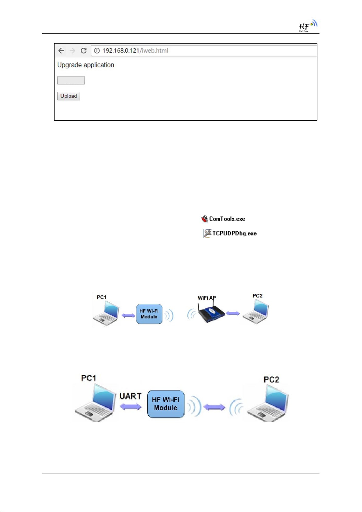
3.1.11. Internal Webpage
After wireless connection is OK. Open Wen browser and access “http://10.10.100.254/iweb.html”; It
is for upgrading application and external webpage..
High-Flying Electronics Technology Co., Ltd(www.hi-flying.com)
- 26 -
HF-LPT130A Low Power WiFi Module User Manual
Select file
No files were selected
Figure 24. Internal Webpage
3.2. Usage Introduction
3.2.1. Software Debug Tools
High-Flying use two common software tools debugging and applying HF-LPT130A module.
(User can also select other tools used to debug serial port).
Serial Debugging Software: ComTools
Ethernet Debugging Software: TCPUDPDbg
3.2.2. Network Connection
User can select two methods to connect HF-LPT130A module base on dedicated application.
Use HF-LPT130A STA interface. HF-LPT130A and debug PC2 connect to a wireless AP,
another PC1 (or user device) connect to HF-LPT130A module with serial port:
Figure 25. STA Interface Debug Connection
Use HF-LPT130A AP interface. Debug PC2 connect to HF-LPT130A through wireless
connection, another PC1 (or user device) connect to HF-LPT130A module with serial port.
Figure 26. AP Interface Debug Connection
3.2.3. Default Parameter Setting
Default SSID: HF-LPT130A;
High-Flying Electronics Technology Co., Ltd(www.hi-flying.com)
- 27 -
HF-LPT130A Low Power WiFi Module User Manual
Deault security mode: open,none;
User UART parameter setting:115200,8,1,None;
Default network parameter setting:TCP,Server,8899,10.10.100.254;
Module IP address: dhcp,0.0.0.0,0.0.0.0,0.0.0.0;
3.2.4. Module Debug
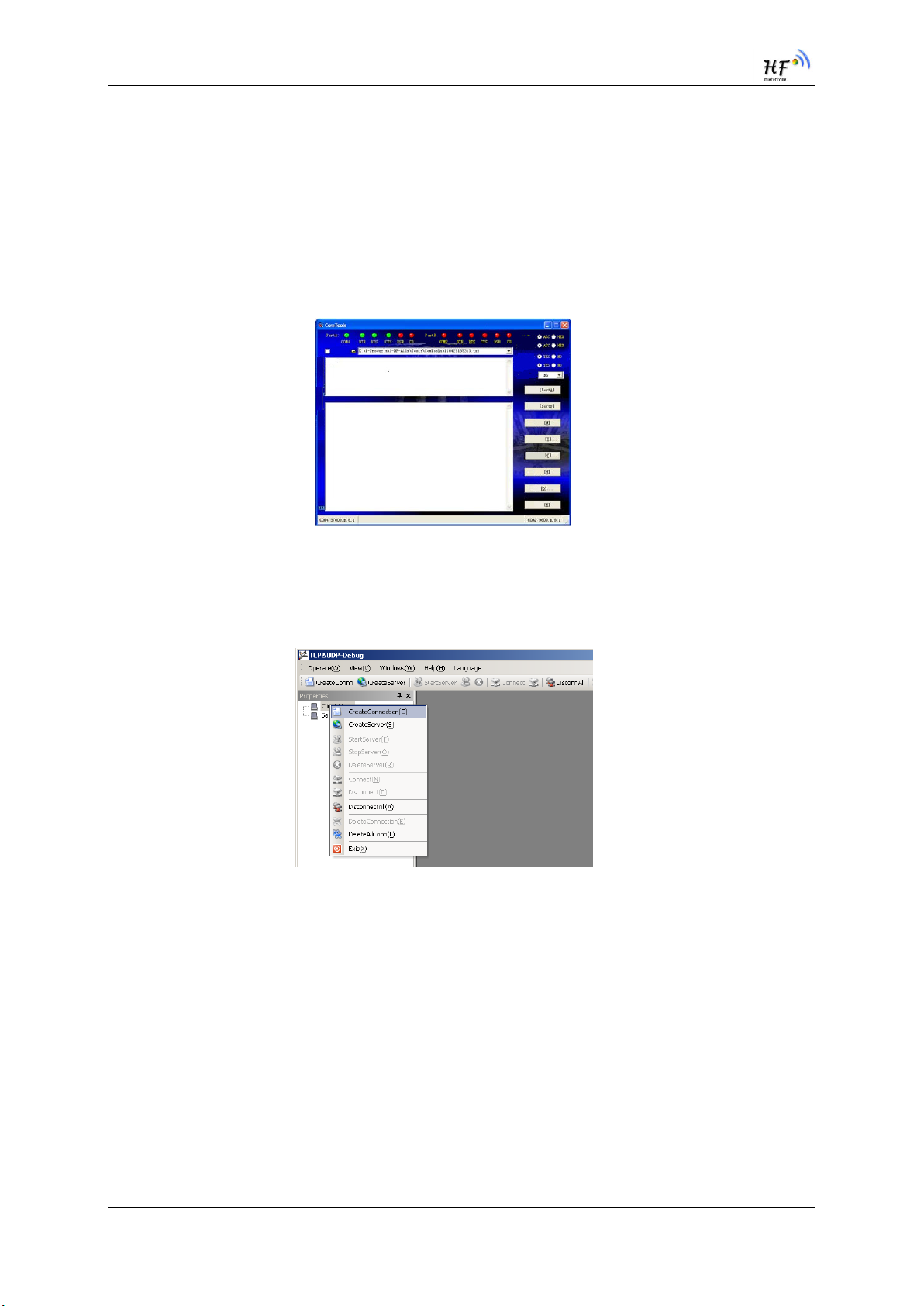
PC1 open “CommTools” program, setting the same serial port parameters with HF-LPT130A module
and open serial port connection.
Figure 27. “CommTools” Serial Debug Tools
PC2 open “TCPUDPDbg” program, and create a new connection. If HF-LPT130A configured as
Server mode, “TCPUDPDbg” Tools shall create “Client “mode connection. Or otherwise, create a
“Server” mode connection.
Figure 28. “TCPUDPDbg” Tools Create Connection
Then setting the TCP/UDP connection parameters. Default as following:
High-Flying Electronics Technology Co., Ltd(www.hi-flying.com)
- 28 -

HF-LPT130A Low Power WiFi Module User Manual
Figure 29. “TCPUDPDbg” Tools Setting
Then, click “Create” button to create a connection.
Figure 30. “TCPUDPDbg” Tools Connection
Now, in transparent transmission mode, data can be transferred from “CommTools” program to
“TCPUDPDbg” program, or in reverse. You can see data in receiver side will keep same as in sender
side.
3.3. Typical Application Examples
3.3.1. Wireless Control Application
Figure 31. Wireless Control Application
For this wireless control application, HF-LPT130A works as AP mode. Module’s serial port connects to
user device. So, control agent (Smart phone for this example) can manage and control the user device
through the wireless connection with HF-LPT130A module.
High-Flying Electronics Technology Co., Ltd(www.hi-flying.com)
- 29 -

HF-LPT130A Low Power WiFi Module User Manual
3.3.2. Remote Management Application
Figure 32. Remote Management Application
For this remote management application, HF-LPT130A works as STA mode and connects to Internet
through wireless AP. Module configured as TCP Client and communicates with remote TCP server at
Internet. Module’s serial port connects to user device.
So, user device’s data or sampling information can send to remote TCP server for storage or
processing. Also remote TCP server can send command to control and manage the user device
through the wireless network.
3.3.3. Transparent Serial Port Application
For this transparent serial port application, two HF-LPT130A modules connect as below figures to
build up a transparent serial port connection. One HF-LPT130A works as AP mode, another HF-
LPT130A works as STA mode. Make the STA device connects to AP.
Figure 33. Transparent Serial Port Application
High-Flying Electronics Technology Co., Ltd(www.hi-flying.com)
- 30 -

HF-LPT130A Low Power WiFi Module User Manual
© Copyright High-Flying, May, 2011
The information disclosed herein is proprietary to High-Flying and is not to be used by or disclosed to
unauthorized persons without the written consent of High-Flying. The recipient of this document shall respect the
security status of the information.
The master of this document is stored on an electronic database and is “write-protected” and may be altered only
by authorized persons at High-Flying. Viewing of the master document electronically on electronic database
ensures access to the current issue. Any other copies must be regarded as uncontrolled copies.
High-Flying Electronics Technology Co., Ltd(www.hi-flying.com)
- 31 -

FCC Statement
Any Changes or modifications not expressly approved by the party responsible for
compliance could void the user’s aut hority to operate the equipment.
This device complies with part 15 of the FCC Rules. Operation is subject to t he
following t wo conditions:
(1) This device may not cause harmful interference, and
(2) This device must accept any interference received, including int erference that
may cause undesired operation.
FCC Radiation Exposure Statement:
This equipment complies with FCC radiation exposure limits set forth for an
uncontrolled environment .This equipment should be installed and operated with
minimum distance 20cm between the radiator& your body.
FCC Label Instructions
The outside of final products that contains this module device must display a label
referring to the enclosed module. This exterior label can use wording such as: “Contains
Transmitter Module FCC ID:2ACSV-HF-LPT130A”,or “Contains FCC ID:2ACSV-HF-LPT130A”,
Any similar wording that expresses the same meaning may be used.
 Loading...