

Page 1

Mo
de
E
sc.
Hold
for
Automated Luminaire
User Manual
Version 1.0 — Revision C
Page 2

To view a list of ETC trademarks and patents, go to etcconnect.com/ip. All other trademark s,
both marked and not marked, are the property of their respective owners.
Information and specifications in this document are subject to change without notice.
Page 3

Table of Contents
Introduction
Contacting High End Systems 1
Headquarters
Technical Support
Patents 1
Terms and Conditions and Warranty Information 1
Product Modification Warning 2
Mise En Garde Contre La Modification Du Produit
Produktmodifikationswarnung
Av vertenza Sulla Modifi ca Del Prodotto
Advertencia De Modificatión Del Producto
Declaration of Conformity 3
Important Safety Information 4
Fixture Overview
1
1
1
2
2
2
2
5
Dimensions 6
Safety Considerations
General Operation and Use Guidelines 8
Install the Fixture
Power
Input and Power Factor 11
Connector Specification 11
DMX Control
DMX Connector Pinout 12
7
9
11
12
Table of Cont ents i
Page 4

Connect DMXCables to Fixture 12
DM X Control and Ethernet Output
Terminate DMX 13
Set the DMX Start Address 13
DMX Channels 13
LED Cell Layout 14
Ethernet Control
Connect EthernetCables to a Fixture 15
Ethernet Control and DMX Thru
Set the DMX Start Address 16
Set the Control Input and Universe 16
Configure the Fixture
Navigate the User Interface 17
13
15
16
17
DMX Address 17
Settings Menu 18
Set the Control Options
Set the Network Options
Set the Pan/Tilt Options
Set the Dimming Options
Set the Fan Options
Set the Display Options
Software Update
Calibration Options
Restore Defaults
18
18
19
19
20
20
20
20
20
Home/Test Menu 21
Home Options
Test Options
21
21
Diagnostics Menu 22
Set Time Options
View Errors
View Fan Speed
View Sensors
22
22
22
22
ii Tur boRay User Manual
Page 5

View Temperatures
View D MXMonitor
View Software Version
View D evice
23
23
23
23
Error Codes
Cleaning and Maintenance
24
27
Table of Cont ents iii
Page 6

Introduction
Congratulations on your purcha se of the TurboRay a utomated fixture. This manual provides
important informa tion for the safe installation, configuration, and maintenance of your
TurboRay fixture.
Contacting High End Systems
High End Systems, Inc. is an ETC company.
Headquarters
For Custome r Service or Sales support, please contact our company headquarte rs:
2105 Gracy Farms Lane
Austin, TX 78758 USA
Te l: 512.836.2242
Fax: 512.837.5290
Toll-free: 800.890.8989
Website: highend.com
Technical Support
If you are having difficultie s installing, configuring, or operating your TurboRay, your most
convenient resources are the references given in this manual. T o search more widely, try the
High End Systems, Inc. website at highend.com. Additional technical resources are ava ilable on
the support website support.etcconnect.com/HES.
If you have additional questions that cannot be answered within these resources, contact High
End Systems Technical Services directly a t the office nearest you. Emergency support is
available outside of regula r business hours. Contact information is a vailable at
highe nd.com/a bout/contact-us.
Patents
NO T ICE OF INTE LLEC TUAL P ROP ERT Y RIGHT S
High End Systems, Inc. products are prote cted by one or more patents listed on the High End
Systems, Inc. website: https://www.highend.com/pa tents and/or are subject to one or more
pending patents.
Terms and Conditions and Warranty Information
Complete te rms and conditions and warranty information can be found on the High End
Systems, Inc. website:https://www.highend.com/pub/products/HES-Warranty-Information.pdf.
1 Tur boRay User Manual
Page 7

Product Modification Warning
High End Systems products are designed and manufactured to me et the requirements of the
United States and International safety regulations. Modifications to the product could affe ct
safety and render the product non-compliant to relevant safety standards.
Mise En Garde Contre La Modification Du Produit
Les produits High End Systems sont conçus et fabriqués conformément aux exigences de
règlements internationaux de sé curité. Toute modication du produit peut entraîner sa non
conformité aux normes de sécurité en vigueur.
Produktmodifikationswarnung
Design und Hestellung von High End Systems e ntprechen den Anforderungen der U.S.
Amerika nische n und interna tionalen Sicherheithsvorschriften. Abänderungen dieses P roduk tes
können dessen Sicherheit beeinträchtigen und unter Umständen gegen die diesbezüglichen
Siche rheitsnormen verstoße n.
Avvertenza Sulla Modifica Del Prodotto
I prodotti di High End Systems sono stati progettati e fa bbricati per soddisfare i requisiti delle
normative di sicurezza statunitensi ed inte rnazionali. Qualsiasi modifica al prodotto potrebbe
pregiudicare la sicurezza e rendere il prodotto non conforme agli standard di sicurezza
pertinenti.
Advertencia De Modificatión Del Producto
Los productos de High End Systems están diseñados y fabricados para cumplir los re quisitos de
las reglamentaciones de seguridad de los Estados Unidos e internacionales. Las modificaciones
al producto podrían afectar la se guridad y dejar al producto fuera de conformidad con las
normas de seguridad relevantes.
Int roduct ion 2
Page 8

Declaration of Conformity
Declaration
of
Conformity
Manufacturer’s name: High End Systems, Inc.
Manufacturer’s address: 2105 Gracy Farms Lane
Austin, Texas 78758 USA
Distributor’s name: High End Systems, Inc.
Distributor’s address: 2105 Gracy Farms Lane
Austin, Texas 78758 USA
Product Name: Turbo Ray
Product Options: All
We hereby declare that the above referenced product complies with the essential requirements
of Council Directives 2014/30/EU (EMC), 2014/35/EU (LVD) and 2011/65/EC (RoHS) .
Safety: EN 60598-1: 2015 + A1:2018
EN 60598-2-17: 2018: 1991
EN62493 (2015)
EN62031:2008 +A1:2013 +A2:2015
EN62471 (2008)
EN61347-2-11: 2001;
EN61347-1: 2015
EMC: Emission: EN55032: 2015
EN61547:2009
EN 61000-3-2 (2014)
EN 61000-3-3
(2013)
3 Tur boRay User Manual
Page 9
Important Safety Information
Please read all instructions prior to assembling, mounting, and operating this equipment.
Continued and safe operation of this fixture is the responsibility of the ope rator. This manual will
give tips for that continued safe operation. At any time please contact High End Systems
technical support for any safety concerns.
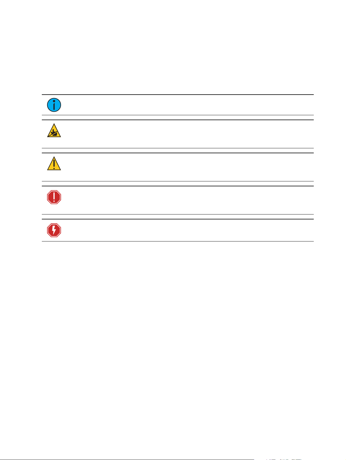
The following international note, caution, and warning symbols appear in ma rgins throughout
this manual to highlight important message s.
Note:
CAUTION:
surfaces may reach very high temperatures. A llow the fixture to cool before
handling or servicing.
CAUTION:
undefined or unwanted consequences of an action, potential for data loss or
an equipment probl em.
Notes are helpful hints and information that is supplemental to the main text.
This statement indicates that while operating, equipment
A Caution statement indicates situations where there may be
WARNING: A Wa rning stateme nt indica te s situa tions where damage ma y
occur, people ma y be harme d, or there are se ri ous or dangerous
consequence s of an a ction
WARNING: RISK OF ELECT RIC SH OCK! T his warning sta tement indicates
situa tions where the re is a risk of ele ctric shock.
Int roduct ion 4
Page 10
Fixture Overview
2
1
Mode
Esc.
Hold
for
•
•
7
5
4
6
3
•
•
•
•
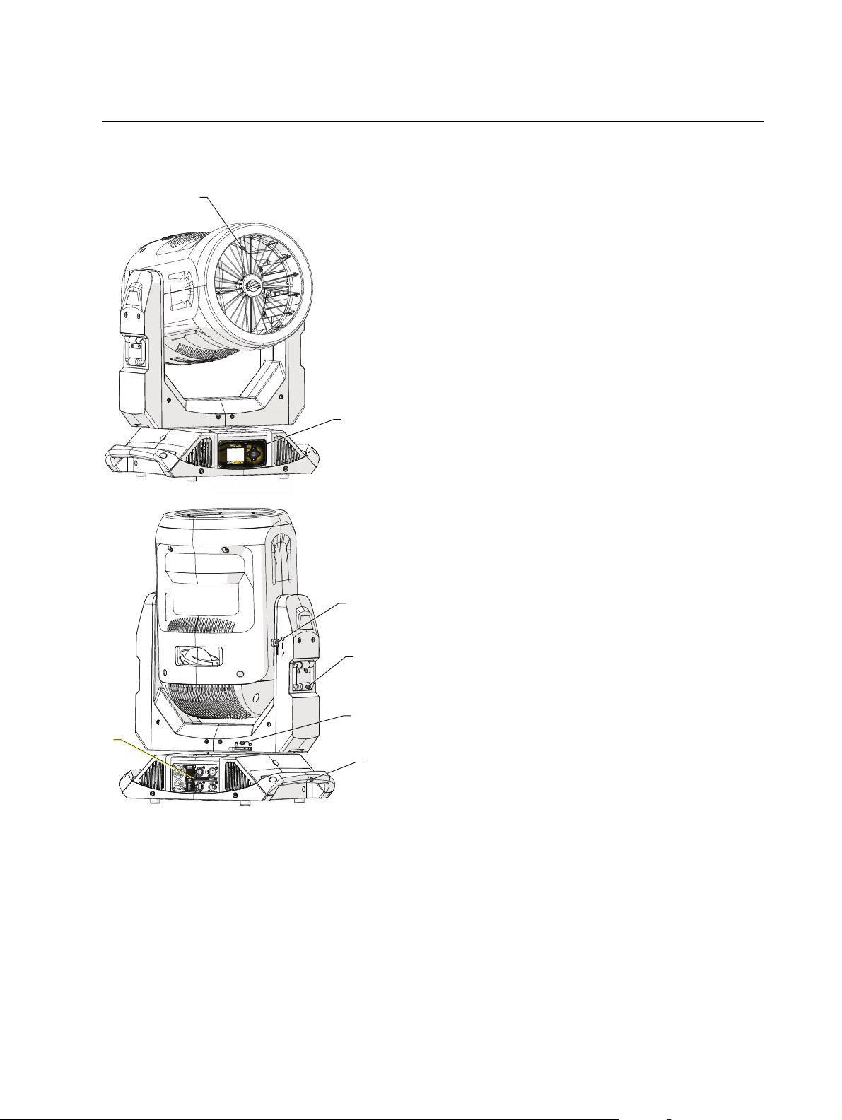
For technica l specifications of the TurboRay fixture, se e the technica l data sheetat
highe nd.com.
1. Primary (radial) diffusers (16-segments)
2. User interface
full-color graphical display
six-button navigational controls
3. Tilt lock
4. Yoke ha ndle
5. Pan lock
6. Input and Output panel
powerCON®TRUE1™ input and thru
DMX five-pin XLR input and thru
Ethernet input and thru (Art-Net)
USB
7. Enclosure handle
5 Tur boRay User Manual
Page 11
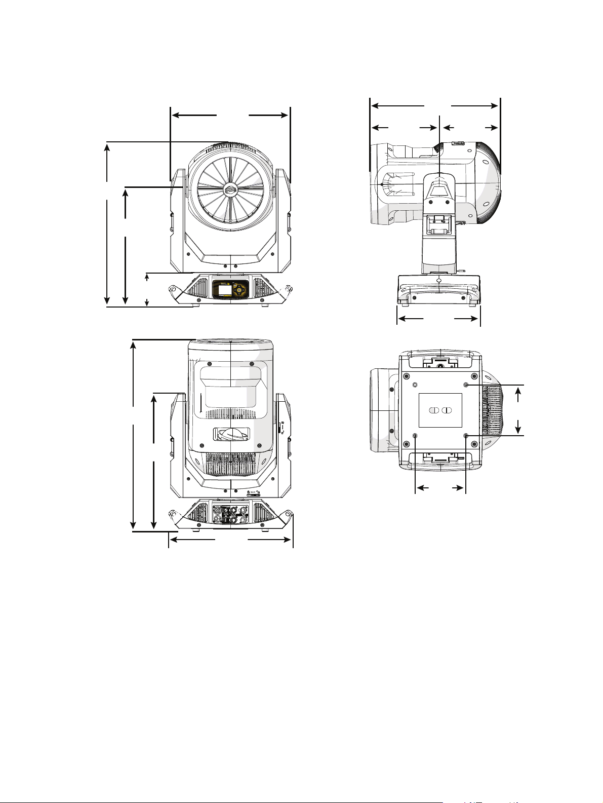
Dimensions
Mode
Esc.
Hold for
67 cm
(26.4 in)
41.4 cm
(16.3 in)
11.4 cm
(4.5 in)
66.3 cm
(26.1 in)
48 cm
(18.9 in)
47 cm
(18.5 in)
41.7 cm
(16.4 in)
29.7 cm
(11.7 in)
42.9 cm
(16.9 in)
24.3 cm
(9.8 in)
22.1 cm
(8.7 in)
18 cm
(7.1 in)
18 cm
(7.1 in)
Dimensions shown are listed as ce ntimeter (inch).
Fix ture Over view 6
Page 12

Safety Considerations
•
•
•
•
•
•
•
•
•
•
•
•
In order to ensure safe operation, follow the safety instructions a nd warning notes in this user
manual and any instructions from the manufacturer representative .
The TurboRay fixture is intended for professional use only. Not for residential use. Read
the entire manual be fore using this equipment.
Conta ct your High End Systems dealer or High End Systems technical support before
performing any service in order to maintain warranty coverage.
WARNING: For your safety, read the following warnings and notice s
before use :
This equipment i s designed for operation by qua lified pe rsonnel only.
Di sconnect the unit from power a nd DMX and data before servicing.
Mak e sure that the ava ilable v olta ge is within the sta ted range.
NE M A Type 1 enclosure, indoor use, dry locations only. Do not use
outdoors. This fixture is i ntended for use where humidity doe s not
exceed 90% (non-condensi ng).
Do not use this fixture with a da maged powe r le ad ( cord set) . If the
le a d is damaged, it must be replaced by a qua lifie d technician with an
equival ent type be fore use. Contact your loca l authorized de aler for
spa re powe r le a ds.
Do not use this fixture if the lens is damage d. Dama ged lenses must be
replace d before use . Contact your local authorize d dealer for a
replace ment.
When the fixture has be e n stored or tra nsported in cold te mperatures,
allow it to warm to room te mperature for a minimum of one hour
before applying power. Applying power to a cold fixture may cause
dama ge to the fixture and void the ma nufacturer warranty.
This is a Class 1 device and must be grounded. Follow na ti onal a nd
local codes.
Ke ep fixture he ad a t le a st 1.0 m awa y from any flammable materials.
Minimum distance to lighted obje cts:1.0 m.
CAUTION:
Hot Surfaces. Allow the fixture to cool completely before
handling and serv icing.
CAUTION:
Damages caused by the disregard of this user manual are not
subject to warranty. High End Systems, Inc. and its authorized dealers will not
accept liability for any resulting defects or problems.
7 Tur boRay User Manual
Page 13

General Operation and Use Guidelines
•
•
•
•
•
•
•
•
•
•
•
•
This fixture is only allowed to be operated with the maximum alternating current that is
stated in the te chnical spe cifications label provided on the fixture.
Lighting effects are not designed for perma nent operation. Consistent ope ration bre aks
may ensure that the fixture will serve you for a long time without defects.
Do not shake the fixture. Avoid brute force when installing or operating the fixture.
When choosing the installation location, make sure that the fixture is not exposed to
extreme heat, moisture, or dust.
If using the supplied Ome ga brackets with quick-locking thumb screws for fixture hanging,
ensure that the thumb screws have engaged a complete 90-degree positive latch.
Operate the fixture only after having familiarized yourself with its functions. Do not permit
other persons who are not qualified and familiar with its functions to operate the fixture .
Please use the original packaging if the fixture is to be transported. ETC and High End
Systems, Inc. will not be responsible for the fixture if packaging other than manufacturer
provided packa ging is used.
Do not modify the fixture. Any modifications will void the warranty.
This manual describes the proper installation and operation of this fixture. Using this
fixture in any way other than the intende d use may cause damage and may void the
warranty.
Misuse of this fixture or using it in a way different from the methods described in this
manual may lead to personal injury a nd/or equipment failure.
The light source of this fixture is not replaceable. When the light source reaches its end of
life, replace the fixture.
If you do not provide power to the fixture, the battery on the TurboRay may drain fully
after 7–10 days. After you provide power to the fixture, the battery will recharge within 3–
4 hours.
Safety Considerations 8
Page 14

Install the Fixture
•
•
•
•
•
•
•
•
•
•
WARNING:
The installation location must support a minimum point loa d of 1 0
times the we ight of the fixture.
The installation must always be se cured with a secondary safe ty
attachme nt. An appropriate safety ca bl e is supplied.
Sa fety cable atta chment must be ra ted by a sa fety factor of 10.
Use of third party clamps are permitted, but they should comply with,
and be approve d by, the Authority Havi ng Jurisdiction (AHJ) .
A supportive and sta ble surfa ce must be used when the fixture s are
placed on the feet.
The operating tempe ra ture ra nge for thi s fixture is 0-40°C. Do not
ope rate the fixture outside of this range.
Ne ver stand directly below the insta lled fixture when mounting,
removing, or se rv icing the fixture.
Al l sa fe ty a nd technica l aspe cts of fixture installa tion must be
approve d by a qualified pe rsonnel before operation.
The installation must be re gularly inspecte d by qua lified pe rsonnel.
Overhead rigging must be performed by qualified pe rsonnel.
CAUTION:
Follow all local codes and recommended practices by the
Authority Having Jurisdiction. The installation must only be carried out by
qualified personnel.
You can install the fixture in any of the orientations shown below.
9 Tur boRay User Manual
Page 15

1
2
3 5
1. Assemble the clamp (provided by others) to the Omega bracket and se cure toge ther using
appropriately sized hardware ( not provided).
2. Align the asse mbled Omega bra cket and quick-lock fasteners into the respective holes on
the bottom of the fixture upper enclosure.
3. Tighten each of the quick-lock fasteners fully, turning clockwise. You will hear and feel a
click when the fastener is fully se cured.
4. Repeat steps 1 through 3 for the se cond clamp and brack et.
5. Attach the provided safety cable through the attachment point on the bottom of the
fixture upper enclosure and secure to the trussing system or other safe installation point.
Follow local codes and recommende d safety standards for securing the fixture to the
installation location.
6. Attach the fixture to the installation location using the installed clamps, using the clamp
manufacturer's instructions for a secure fit. When using the Omega clamp, close the
safety and fully tighten the clamp wing nut until secure.
7. Inspect the installation prior to lifting the fixture overhe ad.
Inst all the Fixture 10
Page 16

Power
Input and Power Factor
VAC AMPS Hz Watts VA PF
100 4.29 50 428 430 0. 99
120 3.48 60 416 418 0. 99
200 2.06 50 400 413 0. 97
208 1.97 60 401 411 0. 97
220 1.87 50 398 412 0. 96
240 1.74 60 403 418 0. 96
Connector Specification
A fixture powe r cord with powerCON TRUE1 input to bare end is provided. Install a suitable
conne ctor to meet the installation requirements. See the following wire color code chart:
Wire Color Code
(EU)
Green/Yellow Green Ea rth/Ground
Blue White Neutral N
Brown Black Line (Live) L
Wire Color Code
(US)
Conne ction
type
Te rminal
WARNING: RISKOFEL ECT RICSHOCK! The powerCON T RUE 1 is a
connector system consisting of the cable conne ctor and the chassis
rece ptacle. A cable connector i nserted the incorre ct wa y could, in some
circumstances, le ad to conta ct be tween liv e wire s and the grounding conta ct
in the plug socket resulting in e quipme nt ma lfunction and/or personal
injury.
Che ck the condition of your powe rCON TRUE1 connector system ( cable
connector a nd chassis re cepta cle ) for cle ar signs of we ar a nd te ar.
Refere nce the Ne utrik Safety Notice powerCON TRUE1 for more safety
information.
11 Tur boRay User Manual
Page 17

DMX Control
DMX-512
(Belden 9729 or equivalent)
terminate DMX
with a 120 Ohm
resistor
DMX-512
control
source
The TurboRay fixture operates on standard DMX-512 control bus, controlled by a DMX console.
The fixture requires 53 channels of DMX-512 in standard mode.
Two XLR termination receptacles are available: one for connection of DMXInput, and one for
DMXThru (used when daisy-chaining to additional fixtures on the DMX control bus).
DMX Connector Pinout
For DMXInput, the DMX cable must have a ma le XLR connector on one end of the cable that
conne cts to the fixture. When daisy-chaining DMX to the next device, prepare a DMX cable with
a female XLR connector on one end and a male XLR connector on the other end. Terminate the
cable ends as indicated in the pinout image below.
Connect DMXCables to Fixture
The following instructions are guidelines for connecting DMX to your fixture. Your installation
may vary.
1. Conne ct the male XLR connector of a DMX data cable to the DMXThru connector on the
DMX control source.
2. Conne ct the female XLR connector of the DMX data cable to the DMX In connector of the
first fixture on the DMX control run.
3. Continue linking the remaining fixtures by connecting a cable from the DMXThru
conne ctor of a fixture to the DMXIn conne ctor of the next fixture on the control run.
Note:
when installed in a daisy-chain fashion.
A maximum of 32 DMX device s may be connected in any one DMX data run
DMX Cont rol 12
Page 18

DMX Control and Ethernet Output
You can use DMX-512 control and Ethernet output. When a fixture is set up to receive DMX-512
control input, it conve rts the signal to Art-Net on IP10 and sends the signal to the Ethernet port,
continuing the Art-Net on IP10 signal to the next fixture in the control run.
Terminate DMX
Use a DMX terminator or install a resistor on the last fixture of the DMXcontrol run to prevent
corruption (data reflection) of the digital control signal by ele ctrical noise.
A DMXterminator is an XLR plug with a 120 Ω resistor conne cted between pins 2 and 3 that can
be installed into the DMX output receptacle of the last fixture in the DMX control run. This plug
is ava ilable and sold separately. Contact your local High End dealer for ordering information
(visit highend.com/about/contact-us to locate a High End deale r).
Set the DMX Start Address
Give each fixture a unique DMX starting address so that the correct fixture re sponds to the
control signals. This DMX start address is the cha nnel number from which the fixture starts to
“listen” to the digital control informa tion sent out from the control source.
Modify the fixture DMX start address on the user inte rface, located on the upper enclosure. See
DMX Address on page17
Example: The TurboRay requires 53 channels of control in standa rd mode. If you set
the DMX starting address of the first fixture to 1, you could set the second fixture to 54
(53+1), the third to 108, a nd so on.
.
DMX Channels
The most current DMX Map data for the TurboRay can be found on the High End Systems, Inc.
website:
highe nd.com/docume ntation/TurboRay/TurboRay-protocol.pdf
13 Tur boRay User Manual
Page 19

LED Cell Layout
2 1
3 4
LED modules are arranged according to the image be low.
Notice in the above image how the fixture head is oriented in relation to the pan and tilt locks.
DMX Cont rol 14
Page 20

Ethernet Control
Ethernet
control
source
Cat 5e (or better) Cat 5e (or better)Cat 5e (or better)
The TurboRay fixture includes two Ethernet ports that allow sending and receiving of control
signals using the Art-Net protocol .
Use a Cat5e (or better) cable and terminate to RJ45 connectors following the TIA/EIA 568B
wiring standard.
Connect EthernetCables to a Fixture
The following instructions are guidelines for connecting Ethernet to your fixture. Your
installation may vary.
1. Conne ct a cable from the Ethernet control source to one of the Ethernet ports on the first
fixture in the E thernet control run.
2. Conne ct the first fixture to a second fixture by connecting a cable from the second
Ethernet port on the first fixture to one of the Ethernet ports on the second fixture.
3. Continue linking the remaining fixtures by connecting a cable from Ethernet port to
Ethernet port on the fixtures on the control run.
Note:
The Cat5e cable distance should not exceed 100 m, and you should not
conne ct more than 20 fixtures in one Ethernet control run when the fixtures are linked
together.
15 Tur boRay User Manual
Page 21

Ethernet Control and DMX Thru
Ethernet
control
source
Universe 1
Cat 5e (or better)
to Ethernet port
Universe 1
Belden 9729 (or equivalent)
to DMX In port
Universe 1
Belden 9729 (or equivalent)
to DMX In port
You can use Ethernet control and DMX Thru. When a fixture is set up to receive E thernet control
input, it automatically distribute s DMX via the DMX Thru port. T he DMX-512 signa l is sent as a
single universe that corresponds to the universe of the fixture that is receiving Ethernet control.
Set the DMX Start Address
Give each fixture a unique DMX starting address so that the correct fixture re sponds to the
control signals. This DMX start address is the cha nnel number from which the fixture starts to
“listen” to the digital control informa tion sent out from the control source.
Modify the fixture DMX start address on the user inte rface, located on the upper enclosure. See
DMX Address on the next page
.
Example: The TurboRay requires 53 channels of control in standa rd mode. If you set
the DMX starting address of the first fixture to 1, you could set the second fixture to 54
(53+1), the third to 108, a nd so on.
Set the Control Input and Universe
For Ethernet control, you must configure the control input (Art-Ne t) and set a universe (000-255)
for ea ch fixture. See
page18
for details.
Se t the Control Options on page18
and
Se t the Network Options on
Ethernet Cont rol 16
Page 22

Configure the Fixture
Mode
Esc.
Mode
Esc.
Mode
Esc.
You can configure TurboRay fixture through the onboard user interface.
Navigate the User Interface
1.
Press the [MODE /ESC] button (
when the fixture has no power.
2. Browse the menu by pressing the up, down, left, or right navigation buttons.
3.
Press the [Enter] button ( ) to se lect a me nu item.
4. Modify the selection by pressing the up, down, left, or right navigation buttons according
to the selection.
5.
Press the [Enter] button ( ) to confirm a modified selection.
6.
To exit the menu or selection, press the [MODE/ ESC] (
)to access the menu. The display is powered by battery
)button.
Note:
If you press the [Enter] button to confirm a se lection and push no othe r buttons,
the user interface returns to the default displa y a fter 10 seconds.
DMX Address
Na vigate:Main Me nu → DMX Address
Se t the DMX address for the fixture . The default value is 001.
17 Tur boRay User Manual
Page 23

Settings Menu
•
•
•
Na vigate:Main Me nu → Settings
The Settings menu provides access to configure and set up the TurboRay. See
Interface on the previous page
The fixture use r interface is supplied with an auxiliary battery which enables configuration and
menu navigation when AC power is removed.
for information about the na vigation buttons.
Navigate the User
Set the Control Options
Na vigate:Main Me nu → Settings → Control
Pa rameter Value Description
DMX Mode
Data Loss
Protocol
Standard (53)
Reduced (25)
Hold Last Look
Wait and Fade
DMX
Art-Net
Se ts the DMX control mode.
The default setting is Standard.
Se ts the control mode when DMX is not connected.
The default setting is Hold Last Look.
Se ts the control mode.
The default setting is DMX. When Art-Net is selecte d,
additional properties are require d in the Settings > Network
menu.
Set the Network Options
Note:
The Network me nu is hidden when the Control Protocol setting is DMX.
Na vigate:Main Me nu → Settings → Network
Pa rameter Value Description
When Art-Net is the
selected Control
Universe
IPAddress
Net (Art-Net only) 0-127 Se ts the Net value. The default setting is 0.
Protocol
any value from
0-255
When Art-Net is the
selected Protocol
2.XXX.XXX.XXX
10.XXX.XXX.XXX
Se ts the unive rse .
The default setting for Art-Net is 0.
Se ts the IPaddress.
The default setting for Art-Net is
2.000.000.000.
Configur e the Fixt ur e 18
Page 24

Set the Pan/Tilt Options
Na vigate:Main Me nu → Settings → Pan/Tilt
Pa rameter Value Description
Pa n Invert
Off
On
Off
Tilt Invert
On
Off
Pa n/Tilt Swap
On
Off
Pa n/Tilt Fee dback
On
When se t to On, inverts pan movement of the fixture to
the opposite direction. The default setting is Off.
When se t to On, inverts tilt movement of the fixture to
the opposite direction. The default setting is Off.
When se t to On, pan responds to the tilt channels and tilt
responds to the pan channels. The de fault setting is Off.
When se t to On, the pan and tilt encoder's will
feedback , correcting the fixture position when it has
been ma nually moved outside of control. You may want
to turn Pa n/Tilt Feedback to the Off setting when
working on a fixture so tha t you can move the pan and
tilt without correction. The default setting is On.
Set the Dimming Options
Na vigate:Main Me nu → Settings → Dimming
Pa rameter Value Description
Square Law
Curve
PW M Frequency
Red Shift
Inv Square Law
S Curve
Linea r
17.6 kHz
4.4 kHz
2.2 kHz
1.1 kHz
On
Off
Se t the dimming curve. The default setting is
Square Law.
Se t the frequency in Hz at which the LED array
pulses, or blinks, a s a function of Pulse Width
Modulation (PW M). The frequency is adjustable
in order to avoid visible flicker on video and
film. The default setting is 17.6 kHz.
When se t to On, the output replicate s the
warming of an incandescent filament's color
temperature change as it dims. The default
setting is Off.
19 Tur boRay User Manual
Page 25

Set the Fan Options
•
•
•
•
Na vigate:Main Me nu → Settings → Fan
Displa ys the fa n mode settings. O ptions include:Standard, Studio, Continuous, Studio
Continuous. The default setting is Standard.
Standard
Studio (reduces fan noise, but decrea ses fixture output by ~20%)
Continuous
Studio Continuous (fan runs continuously a t a reduced rate, but fixture output decreases
by ~20%)
Set the Display Options
Na vigate:Main Me nu → Settings → Display
Pa rameter Value Description
Timeout
Always On
30s Delay
Automatic
Flip
Flip
Brightness 1-100 (full)
Se t the display timeout. The default se tting is 30s
Delay which turns the display back light off after 30
seconds of inactivity.
Se t the display orientation. When set to Automatic,
the accelerometer in the fixture determines the
orientation. Use the Flip menu option to manually
override the current orientation, flipping the current
state 180°. The default setting is Automatic.
Se t the display ba ck light brightness.
The default setting is 100.
Software Update
Conta ct High End Systems, Inc. Technical Support for assistance to update software.
Calibration Options
Na vigate:Main Me nu → Settings → Calibration
This menu is passcode protected and reserved for authorized technician use only. Contact High
End Systems Technical Support for assistance.
Restore Defaults
Na vigate:Main Me nu → Settings → Restore Defaults
Se lecting and confirming this option restores the fixture to its factory default settings.
Configur e the Fixt ur e 20
Page 26

Home/Test Menu
•
•
•
•
•
•
•
•
•
•
•
•
•
Na vigate:Main Me nu → Home/Test
The Home/Test menu provides access to rehome and test the TurboRay fixture mechanical
features and attributes.
The fixture must be powered prior to rehoming or testing fe atures and attributes. If you do not
provide power, the fixture will use battery powe r to power only the user interfa ce.
Home Options
Na vigate:Main Me nu → Home/Test → Home
Home (reset) the selected features:
All - homes all mechanical features of the fixture including pan, tilt, color, gobo, diffusion,
and zoom
Pa n/Tilt - homes the pan and tilt
Color - homes the color wheel
Gobo - homes the gobo wheel
Diffusion - homes the primary (radial) diffuser
Zoom - homes the optics system
Test Options
Na vigate:Main Me nu → Home/Test → Test
Run a self-test program on feature s and attributes of the TurboRay fixture. When you run the
test, the display indicates "Running" and the fixture a utomatically runs a self-test proce dure,
testing each of the functions. Press [MODE/ESC] button to end the self-test and re turn the
display to the previous menu.
All - runs a self-test on all mecha nical features of the fixture including pan, tilt, color,
gobo, diffusion, and zoom
Pa n/Tilt - runs a self-test on the pan and tilt
Color - runs a self-test on the color wheel
Gobo - runs a se lf-test on the gobo wheel
Diffusion - runs a self-test on the primary (radial) diffuser
Zoom - runs a self-test on the optics system
Light Engines - runs a self-test on the LEDs
21 Tur boRay User Manual
Page 27

Diagnostics Menu
Na vigate:Main Me nu → Diagnostics
Set Time Options
Na vigate:Main Me nu → Diagnostics → Time
Pa rameter Value Description
Total Fixture Hours
Fixture Hours
Total LE DHours
LED Hours
Reset
read only
value in
hours
read only
value in
hours
Enter
Pa sscode
Total run time of the fixture, shown in hours (h). The
counter cannot be re set by the user.
Run time of the fixture since the last rese t, shown in
hours (h). The counter is reset only from the Rese t
option which is passcode protected.
Total run time of the LED engine, shown in hours
(h) . The counter cannot be reset by the user.
Run time of the LEDengine since the last reset,
shown in hours (h). The counter is reset only from
the Re se t option which is passcode protecte d.
This protected me nu provides access to reset Fixture
and LEDhours. As neede d, contact Technical
Support at High End Systems for access. See
Conta cting High End Systems on pa ge1
.
View Errors
Na vigate:Main Me nu → Diagnostics → Errors
Errors that are present in the fixture a re shown. Errors will a utomatically clear from the list as
they are mitiga ted.
View Fan Speed
Na vigate:Main Me nu → Diagnostics → Fan Speed
Displa ys the speeds (in %) of the fixture's fans. Information is available for the LEDlight engine
and the power supply unit (PSU).
View Sensors
Na vigate:Main Me nu → Diagnostics → Sensors
Displa ys the status of sensors, which can help you to determine whether the fixture is
recognizing move me nt and position of the fixture attribute. Attributes that report sensor sta tus
include pan, tilt, color, gobo, zoom 1, and zoom 2. The status of the sensor is shown as a green
or red icon that toggles a s the magne t passes the se nsor.
Configur e the Fixt ur e 22
Page 28

View Temperatures
•
•
•
Na vigate:Main Me nu → Diagnostics → Temperatures
Displa ys the current measured tempe rature for the internal fixture attributes (Main Menu →
Diagnostics → T e mperature s → P CB Tempe ratures) such as the display, motor driver, and LED
driver boards. Separately, temperature information is available for the LEDSensors (Ma inMenu
→ Dia gnostics → Temperatures → LE D S ensors) on each of the light engines.
View DMXMonitor
Na vigate:Main Me nu → Diagnostics → DMX Monitor
Displa ys the current DMXvalue for each of the fixture's channels (parameters of the fixture).
Scroll the list to view all available parameters. DMX da ta is not availa ble when DMX is not
conne cted.
View Software Version
Na vigate:Main Me nu → Diagnostics → Software Version
Displa ys the current software version for the fixture, including the display board, fixture pan /
tilt, motor driver boards, and the LED driver boards.
View Device
Na vigate:Main Me nu → Diagnostics → Device
Displa ys the fixture RDMand IP address information (read only).
RDMDevice Label - a compatible RDMcontroller can rea d and write the device label
RDM Device ID - this is a unique device ID
IP Address - this is the address assigned in the Main Me nu → Settings → Control →
Ne twork → Set IP Addre ss menu.
23 Tur boRay User Manual
Page 29

Error Codes
•
•
•
•
•
•
•
•
•
•
•
•
•
•
When you apply powe r to the fixture, it runs a ca libration (homing) sequence and displays a ny
errors that it detects.
Example: For example, when the display shows "Gobo Wheel Sensor", it mea ns the
gobo wheel se nsor was not pre sent when the calibration (homing) process occurred.
When multiple errors are present they will cycle on the display twice, and then the
fixture will reset (re start). Any errors that remain after two rese t cycles are not
correctable by a reset alone and will require service. Please contact support for
technical assistance.
Gobo Wheel Sensor
This message displays after the reset of the fixture if any of the following conditions exist:
the Hall sensor has malfunctioned
the magnet is missing from the gobo wheel
the motor or sensor wire harness is disconne cted or damaged
there is an obstruction, preventing the wheel from moving during homing
the drive motor has malfunctione d
the motor driver circuit has ma lfunctioned
Boot Diff
This message displays after the reset of the fixture if the bootloader for one of the Boot Sectors
does not match the copy of the bootloader stored in the system.
Color Wheel Sensor
This message displays after the reset of the fixture if any of the following conditions exist:
the Hall sensor has malfunctioned
the magnet is missing from the color whe el
the motor or sensor wire harness is disconne cted or damaged
there is an obstruction, preventing the wheel from moving during homing
the drive motor has malfunctione d
the motor driver circuit has ma lfunctioned
Driver Board 1 NR
This message displays after the reset of the fixture if any of the following conditions exist:
the drive r board has malfunctione d
the drive r board power or data wire harness is disconnected or damaged
EE-R Write
This message displays after the reset of the fixture if an error has been detected writing to the
internal setting memory. If this error is encountered, you may have a bad display PCB. Contact
technical support for assista nce.
Error Codes 24
Page 30

LED Driver 1 NR
•
•
•
•
•
•
•
•
•
•
•
•
•
•
•
•
•
•
•
•
•
•
•
This message displays after the reset of the fixture if any of the following conditions exist:
the drive r board has malfunctione d
the drive r board power or data wire harness is disconnected or damaged
LED Driver 2 NR
This message displays after the reset of the fixture if any of the following conditions exist:
the drive r board has malfunctione d
the drive r board power or data wire harness is disconnected or damaged
Pan and Ti lt NR
This message displays after the reset of the fixture if any of the following conditions exist:
the drive r board has malfunctione d
the drive r board power or data wire harness is disconnected or damaged
Pan Driver Fault
This message displays after the reset of the fixture if any of the following conditions exist:
the pa n driver board is above ope rating tempe rature
the drive r board power or data wire harness is disconnected or damaged
Pan Encoder
This message displays after the reset of the fixture if any of the following conditions exist:
the pa n lock is engaged
the magnetic encode r has malfunctioned
the motor driver circuit has ma lfunctioned
the drive motor has malfunctione d
the motor or encoder wire harness is disconnecte d or damaged
Pan Encoder Time Out
This message displays after the reset of the fixture if any of the following conditions exist:
there is an obstruction preventing the unit from correcting itself within 20 seconds
the pa n lock is engaged
the magnetic encode r has malfunctioned
the encoder wire harness is disconnected or damaged
Pan Sensor
This message displays after the reset of the fixture if any of the following conditions exist:
the Hall sensor has malfunctioned
the magnet for the Hall sensor is missing
the motor or sensor wire harness is disconne cted or damaged
the drive motor has malfunctione d
the drive motor circuit has malfunctioned
the pa n belt is broken
25 Tur boRay User Manual
Page 31

Tilt Driver Fault
•
•
•
•
•
•
•
•
•
•
•
•
•
•
•
•
•
•
•
•
•
•
•
•
•
•
•
•
•
This message displays after the reset of the fixture if any of the following conditions exist:
the tilt driver board is above operating temperature
the drive r board power or data wire harness is disconnected or damaged
Tilt Encoder
This message displays after the reset of the fixture if any of the following conditions exist:
the tilt lock is engaged
the magnetic encode r has malfunctioned
the motor driver circuit has ma lfunctioned
the drive motor has malfunctione d
the motor or encoder wire harness is disconnecte d or damaged
Tilt Encoder Ti me Out
This message displays after the reset of the fixture if any of the following conditions exist:
there is an obstruction preventing the unit from correcting itself too long
the tilt lock is engaged
the magnetic encode r has malfunctioned
the encoder wire harness is disconnected or damaged
Tilt Sensor
This message displays after the reset of the fixture if any of the following conditions exist:
the Hall sensor has malfunctioned
the magnet for the Hall sensor is missing
the motor or sensor wire harness is disconne cted or damaged
the drive motor has malfunctione d
the drive motor circuit has malfunctioned
the tilt belt is broken
Zoom 1 Sensor
This message displays after the reset of the fixture if any of the following conditions exist:
the Hall sensor has malfunctioned
the magnet for the Hall sensor is missing from the zoom slide
the motor or sensor wire harness is disconne cted or damaged
the drive motor has malfunctione d
the drive motor circuit has malfunctioned
the zoom 1 belt is broken
Zoom 2 Sensor
This message displays after the reset of the fixture if any of the following conditions exist:
the Hall sensor has malfunctioned
the magnet for the Hall sensor is missing from the zoom slide
the motor or sensor wire harness is disconne cted or damaged
the drive motor has malfunctione d
the drive motor circuit has malfunctioned
the zoom 2 belt is broken
Error Codes 26
Page 32

Cleaning and Maintenance
•
•
•
•
•
CAUTION:
Disconnect the fixture from mains power before starting any
maintenance procedures.
Keep the following in mind during regular service and inspection:
All screws for insta lling the device or parts of the device must be tightly connected and
must not be corroded.
There must not be any deformations to the housing, lenses, rigging, and installation points
(ceiling, suspension, trussing) .
Moving parts must not show any signs of wear and must move smoothly without issue.
The power supply cables must not show any damage, material fatigue, or se diment.
If spare parts are required, order only genuine parts from your local authorized dea ler.
To ensure that the device re ma ins in good work ing condition and does not fail prematurely,
regular maintenance is recommended.
CAUTION:
The lenses and the output window in the TurboRay fixture are
coated with a H azeFree lens coating technology (patent pending) that keeps
the lenses and output window clear when the fixture is used with theatrical
haze. Use of paper toweling or other abrasive, high-friction wipes and
ammonia-based glass cleaners may permanently damage the coating.
If the coating wears away, contact High End Systems, Inc. Technical Servi ces
for assistance.
1. Clean the lenses and the output window only when necessary, and only use a Silky
Microfiber Optical Cloth with purified water or an ammonia-free glass cleaner such as
Miller Stevenson MS-260 Glass Cleaner.
2. Clean the fans regularly to ensure maximum airflow and efficient cooling. This will ensure
that the light source operates in the best possible condition.
3. Have an approved electrician check the fixture each quarter to ensure that circuit contacts
are in good condition. This prevents poor circuit contacts and the overhea ting that results
from it.
27 Tur boRay User Manual
Page 33

Cleaning and Maintenance 28
Page 34

Headqu ar te rs n 2105 Gracy Farms Lane, Austin , TX, 78758 USA n Tel +512 836 2242 n Fax + 512 837 5290
Gl o bal Offi ces n Lo nd on , UK n Ho lzki rchen , DE n Ho ng Kong
Web hig hen d. co m n S upp ort s up po rt .etccon nect. com/H ES
© 2019 El ect ronic Theat re Co nt ro ls, Inc. n Pr oduct i nformat ion and s pecif icati on s su bj ect to ch ange.
ETCi nt ends th is d ocumen t t o be p ro vid ed i n it s ent iret y. n Trad emark and paten t in fo: etccon nect. co m/i p
2591M1200-1.0 Rev C Releas ed 2019-12
 Loading...