

Page 1

fi
User Manual
High End Systems, Inc.
2217 West Braker Lane
Austin, TX 78758 USA
(512) 836-2242
www.highend.com
p/n 60600115 Version 2.0
Page 2

ADDR
Page 3

Page 4

User Manual
© High End Systems, Inc. 1998, All Rights Reserved
Information and Specifications in this document are subject to change without notice.
High End Systems, Inc. assumes no responsibility or liability for any errors or
inaccuracies that may appear in this manual. The system software for the Status Cue
lighting console described in this manual is furnished under a license agreement and
may be used or copied only in accordance with the terms of the agreement.
Technobeam User Manual
P/N 60600115 Version 2.0 July 1999
Printed in the U.S.A.
®
Technobeam® User Manual i
Page 5

Trademarks
Trademarks used in this text: Lightwave Research, High End Systems, Technobeam, LAD,
Status Cue, Intellabeam, Emulator, Dataflash, Fusion Fire and LithoPatterns are registered
trademarks; Laser Aiming Device is a trademark of High End Systems, Inc.
Belden is a registered trademark of Belden, Inc. Philips is a registered trademark of
Philips Lighting Company. ETL and CETL are registered trademarks of Intertek Testing
Services. Other trademarks and trade names may be used in this document to refer to
either the entities claiming the marks and names or their products. High End Systems
disclaims any proprietary interest in trademarks and trade names owned by others.
Patents
Technobeam may use one or more of the following patents: US 4,962,687; US 5,078,039;
UK 2,043,769; US 5,331,822; US 5,402,326; US D 372550; UK 2292896; US D365165; US
5,430,629; US D360,404; US 5,455,748; 0475082; US 5,506,762; M9604224.9; US
5,515,254; US D370080; UK 2.291,814; US 5,545.951; UK 2055842; UK 2,292,530; UK
2294909; UK 2292896; MR 8621996; and US 5,580,164.
Additional patents pending.
FCC Information
This equipment has been tested and found to comply with the limits for a Class A digital
device, pursuant to part 15 of the FCC rules. These limits are designed to provide
reasonable protection against harmful interference when the equipment is operated in a
commercial environment. This equipment generates, uses, and can radiate radio
frequency energy and, if not installed and used in accordance with the instruction
manual, may cause harmful interference to radio communications. Operation of this
equipment in a residential area is likely to cause harmful interference in which case the
user will be required to correct the interference at his own expense.
ii Technobeam® User Manual
Page 6

Declaration of Conformity
according to ISO/IEC Guide 22 and EN45104
Manufacturer’s name:
Manufacturer’s address:
Distributor’s name:
Distributor’s address:
Declares that the product
Product Name:
Product Number:
Product Options:
conforms to the following EEC directives:
73/23/EEC, as amended by 93/68/EEC
89/336/EEC, as amended by 92/31/EEC and 93/68/EEC
Equipment referred to in this declaration of conformity first manufactured in
1997 in compliance with the following standards:
Safety:
EMC:
EN 60598-1 : 1993
EN 60598-2-17 : 1989
EN 60825-1, 1994
EN 55022, Class A ITE
IEC 801-2, 1991 Level 2 (4/8 kV)
IEC 801-3, Draft 5 Level 2 (3 V/m)
IEC 801-4, 1988 Level 2 (1 kV/0.5 kV)
Lightwave Research
2217 West Braker Lane
Austin, Texas 78758 U.S.A.
High End Systems Inc.
2217 West Braker Lane
Austin, Texas 78758 U.S.A.
Technobeam
All
All
A1-A3 : 1993
U.S.A., September 1, 1999
Kenneth Stuart Hansen
, Compliance Engineer
Technobeam® User Manual iii
Page 7

Important Safety Information
Instructions pertaining to continued protection against fire, electric shock, exposure to
excessive ultraviolet (UV) radiation, and injury to persons are found in Appendix D.
Please read all instructions prior to assembly, mounting, and operating this equipment.
IMPORTANT: INFORMATIONS DE SÉCURITÉ
Les instructions se rapportant à la protection permanente contre les incendies,
l’électrocution, l’exposition à un rayonnement ultraviolet (UV) excessif et aux blessures
corporelles se trouvent dans l’Annexe D.
Veuillez lire toutes les instructions avant d’assembler, de monter ou d’utiliser cet
équipement.
WICHTIGE SICHERHEITSHINWEISE
Sicherheitsanleitungen zum Schutz gegen Feuer, elektrischen Schlag, übermäßige UVStrahlung und Verletzung von Personen finden Sie in Anhang D.
Vor der Montage, dem Zusammenbau und der Inbetriebnahme dieses Geräts alle
Anleitungen sorgfältig durchlesen.
INFORMAZIONI IMPORTANTI DI SICUREZZA
Le istruzioni sulla protezione da incendi, folgorazione, esposizione eccessiva a raggi
ultravioletti (UV) e infortuni sono contenute nell’appendice D.
Si prega di leggere tutte le istruzioni prima di assemblare, montare e azionare
l’apparecchiatura.
INFORMACION IMPORTANTE DE SEGURIDAD
En el Apéndice D de este manual se encuentran instrucciones sobre protección continua
contra incendios, descarga eléctrica, exposición excesiva a radiación ultravioleta (UV) y
lesiones personales.
Lea, por favor, todas las instrucciones antes del ensamblaje, montaje y operación de este
equipo.
Product Modification Warning
High End Systems products are designed and manufactured to meet the requirements of
United States and International safety regulations. Modifications to the product could
affect safety and render the product non-compliant to relevant safety standards.
iv Technobeam® User Manual
Page 8

Mise En Garde Contre La Modification Du Produit
Les produits High End Systems sont conçus et fabriqués conformément aux exigences
des règlements internationaux de sécurité. Toute modification du produit peut entraîner
sa non conformité aux normes de sécurité en vigueur.
Produktmodifikationswarnung
Design und Herstellung von High End Systemen entsprechen den Anforderungen der
U.S.A. und den internationalen Sicherheitsvorschriften. Abänderungen dieses Produktes
können dessen Sicherheit beeinträchtigen und u. U. gegen die diesbezüglichen
Sicherheitsnormen verstoßen.
Avvertenz a Sull a Modifica De l Prodotto
I prodotti di High End Systems sono stati progettati e fabbricati per soddisfare i requisiti
delle normative di sicurezza statunitensi ed internazionali. Qualsiasi modifica al
prodotto potrebbe pregiudicare la sicurezza e rendere il prodotto non conforme agli
standard di sicurezza pertinenti.
Advertencia De Modificación Del Producto
Los productos de High End Systems están diseñados y fabricados para cumplir los
requisitos de las reglamentaciones de seguridad de los Estados Unidos e internacionales.
Las modificaciones al producto podrían afectar la seguridad y dejar al producto fuera de
conformidad con las normas de seguridad relevantes.
Warranty Information
Limited Warranty
Unless otherwise stated, your product is covered by a two (2) year parts and labor limited
warranty. The Laser Aiming Device (LAD™) for Technobeam is covered by a six (6) month
parts and labor limited warranty. Dichroic filters and LithoPatterns
glass gobos are not guaranteed against breakage or scratches to coating. It is the
owner’s responsibility to furnish receipts or invoices for verification of purchase, date,
and dealer or distributor. If purchase date cannot be provided, date of manufacture will
be used to determine warranty period.
®
high resolution
Returning an Item Under Warranty for Repair
It is necessary to obtain a Return Material Authorization number (RMA#) from your
dealer or point of purchase
will make the final determination as to whether or not the unit is covered by warranty.
Lamps are covered by the lamp manufacturer’s warranty.
Any Product unit or parts returned to High End Systems must be packaged in a suitable
manner to ensure the protection of such Product unit or parts, and such package shall be
Technobeam® User Manual v
BEFORE
any units are returned for repair. The manufacturer
Page 9

clearly and prominently marked to indicate that the package contains returned Product
units or parts and with a Return Material Authorization (RMA#) number. Accompany all
returned Product units or parts with a written explanation of the alleged problem or
malfunction. Ship returned Product units or parts to: 2227 West Braker Lane, Austin, TX
78758 USA.
Please Note:
Freight Damage Claims are invalid for fixtures shipped in nonfactory boxes and packing materials.
Freight
All shipping will be paid by the purchaser. Items under warranty shall have return
shipping paid by the manufacturer only in the Continental United States.
circumstances will freight collect shipments be accepted.
not include rush expediting such as air freight. Air freight can be sent customer collect
in the Continental United States.
REPAIR OR REPLACEMENT AS PROVIDED FOR UNDER THIS WARRANTY IS THE EXCLUSIVE
REMEDY OF THE CONSUMER. HIGH END SYSTEMS, INC. MAKES NO WARRANTIES, EXPRESS
OR IMPLIED, WITH RESPECT TO ANY PRODUCT, AND HIGH END SPECIFICALLY DISCLAIMS
ANY WARRANTY OF MERCHANTABILITY OR FITNESS FOR A PARTICULAR PURPOSE. HIGH
END SHALL NOT BE LIABLE FOR ANY INDIRECT, INCIDENTAL OR CONSEQUENTIAL
DAMAGE, INCLUDING LOST PROFITS, SUSTAINED OR INCURRED IN CONNECTION WITH
ANY PRODUCT OR CAUSED BY PRODUCT DEFECTS OR THE PARTIAL OR TOTAL FAILURE OF
ANY PRODUCT REGARDLESS OF THE FORM OF ACTION, WHETHER IN CONTRACT, TORT
(INCLUDING NEGLIGENCE), STRICT LIABILITY OR OTHERWISE, AND WHETHER OR NOT
SUCH DAMAGE WAS FORESEEN OR UNFORESEEN.
Warranty is void if the product is misused, damaged, modified in any way, or for
unauthorized repairs or parts. This warranty gives you specific legal rights, and you may
also have other rights which vary from state to state.
Prepaid shipping does
Under no
vi Technobeam® User Manual
Page 10

Table of Contents
Introduction
Features ........................................................................................intro-1
Symbols ........................................................................................intro-3
Document Conventions ................................................................intro-3
Contacting High End Systems ......................................................intro-4
Chapter 1 Preparing to Install Your Fixture
Specifications .....................................................................................1-2
Optional Accessories ..........................................................................1-5
Unpacking the Fixture ........................................................................1-6
Installing the Power Cord Cap ............................................................1-7
Installing the Yoke ..............................................................................1-8
Setting the Fixture Voltage .............................................................. 1-10
Setting the Beam Angle .................................................................... 1-12
Chapter 2 Setting Up Your Fixture
Powering On the Fixture .....................................................................2-2
Overview of Controller Operation ......................................................2-4
Linking the Fixtures to the Controller ................................................2-7
Mounting the Fixture ..........................................................................2-8
Configuring the Fixture ................................................................... 2-13
Upgrading Software ......................................................................... 2-18
Troubleshooting .............................................................................. 2-20
Chapter 3 Using the Menus
Menu System Overview ......................................................................3-2
Menu Map ...........................................................................................3-3
Menu Options .................................................................................. 3-10
Chapter 4 Preset Programming
Programming Overview ......................................................................4-2
Creating a Scene .................................................................................4-4
Synchronizing Preset Playback ...........................................................4-9
Capturing Presets ............................................................................ 4-11
Chapter 5 Using the Laser Aiming Device™ (LAD™)
Safety Precautions ..............................................................................5-2
Technobeam® User Manual vii
Page 11

Overview ............................................................................................5-3
Controlling the Laser ..........................................................................5-5
Troubleshooting .................................................................................5-6
Maintenance .......................................................................................5-8
Chapter 6 Servicing Your Fixture
Precautions .........................................................................................6-2
Replacing Fuses ..................................................................................6-2
Replacing Wheel Components ............................................................6-4
Replacing the Lamp ......................................................................... 6-11
Cleaning the Internal Components .................................................. 6-15
Technobeam Laser Aiming Device™ ................................................ 6-19
Appendix A DMX Protocols
General Information .......................................................................... A-1
Technobeam® Protocol ...................................................................... A-3
Technobeam-i™ Protocol ................................................................... A-7
MSpeed Movement Times ................................................................ A-12
Macro Channel Assignments ........................................................... A-15
Fixture Number to DMX Start Channel ............................................ A-16
Appendix B Factory-Installed Wheels
Technobeam™ Wheels ........................................................................B-1
Appendix C Important Safety Information
English Version .................................................................................. C-1
Appendice C IMPORTANT: INFORMATIONS DE SÉCURITÉ ................. C-2
Anhang C Wichtige Hinweise Für Ihre Sicherheit ............................. C-3
Appendice C Importanti Informazioni Di Sicurezza ........................ C-4
Apéndice C Información Importante De Seguridad .......................... C-5
Vigtig Sikkerhedsinformation - DANMARK ........................................ C-6
Index
viii Technobeam® User Manual
Page 12

Table of Figures
Figure 1-1. Identifying yoke components. ..................................................... 1-8
Figure 1-2. Installing the yoke on the fixture. ............................................... 1-9
Figure 1-3. Removing the door allows you to access the fixture’s voltage
selection switches, as well as wheels and optics. ................. 1-11
Figure 1-4. The three voltage selection switches located next to the LED
display. .................................................................................. 1-11
Figure 1-5. Setting the fixture’s voltage and frequency.............................. 1-11
Figure 1-6. The lens tube contains the zoom lenses. ................................. 1-12
Figure 1-7. Squeeze the two latches on each side of the lens tube to open
the cover................................................................................ 1-12
Figure 1-8. Components of the factory-installed 11 to 17 degree lens set. 1-13
Figure 2-1. The initial LED menu display shows the fixture’s software
version...................................................................................... 2-2
Figure 2-2. Location of the three status LEDs on the fixture’s access door... 2-3
Figure 2-3. Properly-constructed data cabling............................................... 2-5
Figure 2-4. Constructing a data cable terminator.......................................... 2-6
Figure 2-5. Location of the DMX data in (male) and DMX data Out (female)
ports on the fixture’s rear panel............................................... 2-7
Figure 2-6. Connecting fixtures to a controller. Make sure you terminate
the last fixture in the link......................................................... 2-8
Figure 2-7. Use a locking washer when attaching a fixture to a truss. ....... 2-10
Figure 2-8. Always use a safety cable when mounting the fixture. ............ 2-11
Figure 2-9. Location of the T-handle you use to adjust the yoke position. 2-11
Figure 2-10. You can slide the yoke all the way back to allow the fixture
to hang upside-down. ............................................................ 2-12
Figure 2-11. Menu navigation buttons........................................................ 2-13
Figure 2-12. This fixture has software version 3........................................ 2-20
Figure 2-13. Location of the fixture’s exhaust vent. ................................... 2-22
Figure 3-1. Technobeam navigation buttons. ................................................ 3-2
Figure 4-1. Making sure the shutter is open. ................................................. 4-5
Figure 4-2. A dot always appears in the LED display whenever preset
playback is on........................................................................... 4-9
Figure 4-3. When you set up fixtures for synchronized playback on a
DMX 512 link, one and only one fixture must be fixture
number 1 or DMX start channel 1. The last fixture on the
link must be terminated. ....................................................... 4-10
Figure 5-1. The laser light exits the through the same aperture as the
light beam................................................................................. 5-4
Figure 5-2. The ideal position of the laser is no more than 2” (5 cm)
directly above the center point of a perfectly round light
beam. ........................................................................................ 5-4
Figure 5-3. Removing the access door. .......................................................... 5-6
Figure 5-4. LAD wiring connections............................................................... 5-7
Technobeam® User Manual ix
Page 13

Figure 5-5. The laser aiming device circuit board. ........................................ 5-8
Figure 6-1. Removing the door allows you to access the fixture’s voltage
selection switches and fuses, as well as wheels and optics. .... 6-3
Figure 6-2. Locations of the three fuses on the circuit board........................ 6-4
Figure 6-3. Location of the wheels in Technobeam. ..................................... 6-5
Figure 6-4. Push the dichroic toward the large retaining tab to free it
from the wheel tabs. ................................................................. 6-6
Figure 6-5. You can easily tell which side of a dichroic is coated by placing
a pen or other object near the surface; on the coated side,
the reflection from the object will appear to touch the
object........................................................................................ 6-6
Figure 6-6. The rotating litho wheel and rotating effects wheel have
built-in plastic tabs that hold the spring in place. ................... 6-7
Figure 6-7. To replace a static litho in the rotating litho wheel, gently
separate the wheel and reach behind the wheel to push the
litho out. ................................................................................... 6-8
Figure 6-8. Location of the retaining tabs and slot that secure the static
litho in the rotating litho wheel. .............................................. 6-9
Figure 6-9. The gap between the two halves of the rotating litho wheel
must be uniform....................................................................... 6-9
Figure 6-10. An aperture ring, if required, must be placed on top of
the litho/effect and under the spring.................................... 6-10
Figure 6-11. When you replace a rotating litho or rotating effect, make
sure the tip of the spring is fully seated under the wheel
tabs; it cannot protrude from under the tabs........................ 6-10
Figure 6-12. Replacing a custom multi-colored litho in the metal holder. . 6-11
Figure 6-13. Loosening the lamp assembly screws gives you access to
the fixture lamp. .................................................................... 6-12
Figure 6-14. Removing the lamp assembly from the fixture. ..................... 6-12
Figure 6-15. Pull straight up on the lamp, grasping its ceramic base, to
remove it from the assembly................................................. 6-13
Figure 6-16. Hold the lamp by its ceramic base and gently press the two
base pins into the socket....................................................... 6-13
Figure 6-17. You can look at the lamp label text to make sure the lamp
plate is oriented correctly; incorrect orientation can result
in damage to the fixture and the lamp. ................................. 6-14
Figure 6-18. Lamp optimization screws...................................................... 6-15
Figure 6-19. Opening the fixture’s access door. ......................................... 6-16
Figure 6-20. Location of the anti-reflective glass, lenses and hot mirror... 6-17
Figure 6-21. The lens tube contains the zoom lenses. ............................... 6-17
Figure 6-22. Clean both sides of the hot mirror glass. ............................... 6-18
Figure 6-23. The ideal position of the laser is no more than 2” (5 cm)
directly above the center of a perfectly round light beam.... 6-19
Figure 6-24. High-voltage component location........................................... 6-20
Figure 6-25. Orient the fixture directly facing a wall no less than 10 ft.
(3 m) away.............................................................................. 6-21
x Technobeam® User Manual
Page 14

Figure 6-26. Locating the center point of the projected light beam. The
laser should be no more than 2” (5 cm) above the center. .... 6-24
Figure 6-27. The laser aiming device assembly has three screws that can
be used to adjust the position of the laser............................ 6-25
Figure B-1. Factory configuration of the Technobeam rotating litho wheel. . B-1
Figure B-2. Factory configuration of the Technobeam color wheel............... B-2
Figure B-3. Factory configuration of the Technobeam rotating effects
wheel......................................................................................... B-2
Table of Tables
Table 1-1. Optional Accessories .....................................................................1-5
Table 1-2. Beam Angles for Factory-Installed 11 to 17 Degree Lens Set ..... 1-14
Table 1-3. Beam Angles for Optional 8 to 12 Degree Narrow Angle Lens
Set ............................................................................................. 1-14
Table 2-1. Status LEDs ....................................................................................2-3
Table 2-2. Example: Determining the DMX Start Channel .......................... 2-16
Table 2-3. Example: Determining the Unique Fixture Number .................. 2-17
Table 2-4. Example of Wasted DMX Channels ............................................. 2-18
Table 3-1. Technobeam Menu Map ................................................................3-3
Table 6-1. Replacement Fuses ........................................................................6-2
Table 6-2. Fuse Failure Symptoms .................................................................6-3
Table A-1. Technobeam DMX Protocol .......................................................... A-3
Table A-2. Technobeam-i DMX Protocol ........................................................ A-8
Table A-3. MSpeed Movement Times .......................................................... A-13
Table A-4. Macro DMX Channel Assignments ............................................. A-15
Table A-5. Fixture Number to DMX Start Channel Conversion ................... A-16
Technobeam® User Manual xi
Page 15

xii Technobeam® User Manual
Page 16

Introduction
Features ........................................................................................intro-1
Symbols ........................................................................................intro-3
Document Conventions ................................................................intro-3
Contacting High End Systems ......................................................intro-4
Chapter 1 Preparing to Install Your Fixture
Specifications .....................................................................................1-2
Optional Accessories ..........................................................................1-5
Unpacking the Fixture ........................................................................1-6
Installing the Power Cord Cap ............................................................1-7
Installing the Yoke ..............................................................................1-8
Setting the Fixture Voltage .............................................................. 1-10
Setting the Beam Angle .................................................................... 1-12
Chapter 2 Setting Up Your Fixture
Powering On the Fixture .....................................................................2-2
Overview of Controller Operation ......................................................2-4
Linking the Fixtures to the Controller ................................................2-7
Mounting the Fixture ..........................................................................2-8
Configuring the Fixture ................................................................... 2-13
Upgrading Software ......................................................................... 2-18
Troubleshooting .............................................................................. 2-20
Chapter 3 Using the Menus
Menu System Overview ......................................................................3-2
Menu Map ...........................................................................................3-3
Menu Options .................................................................................. 3-10
Chapter 4 Preset Programming
Programming Overview ......................................................................4-2
Creating a Scene .................................................................................4-4
Synchronizing Preset Playback ...........................................................4-9
Capturing Presets ............................................................................ 4-11
Chapter 5 Using the Laser Aiming Device™ (LAD™)
Safety Precautions ..............................................................................5-2
Overview ............................................................................................5-3
Controlling the Laser ..........................................................................5-5
Troubleshooting .................................................................................5-6
Maintenance .......................................................................................5-8
i Ecodome User Manual
Page 17

Chapter 6 Servicing Your Fixture
Precautions .........................................................................................6-2
Replacing Fuses ..................................................................................6-2
Replacing Wheel Components ............................................................6-4
Replacing the Lamp ......................................................................... 6-11
Cleaning the Internal Components .................................................. 6-15
Technobeam Laser Aiming Device™ ................................................ 6-19
Appendix A DMX Protocols
General Information .......................................................................... A-1
Technobeam® Protocol ...................................................................... A-3
Technobeam-i™ Protocol ................................................................... A-7
MSpeed Movement Times ................................................................ A-12
Macro Channel Assignments ........................................................... A-15
Fixture Number to DMX Start Channel ............................................ A-16
Appendix B Factory-Installed Wheels
Technobeam™ Wheels ........................................................................B-1
Appendix C Important Safety Information
English Version .................................................................................. C-1
Appendice C IMPORTANT: INFORMATIONS DE SÉCURITÉ ................. C-2
Anhang C Wichtige Hinweise Für Ihre Sicherheit ............................. C-3
Appendice C Importanti Informazioni Di Sicurezza ........................ C-4
Apéndice C Información Importante De Seguridad .......................... C-5
Vigtig Sikkerhedsinformation - DANMARK ........................................ C-6
Ecodome User Manual ii
Page 18

Figure 1-1. Identifying yoke components. ..................................................... 1-8
Figure 1-2. Installing the yoke on the fixture. ............................................... 1-9
Figure 1-3. Removing the door allows you to access the fixture’s voltage
selection switches, as well as wheels and optics......................................... 1-11
Figure 1-4. The three voltage selection switches located next to the LED display.
1-11
Figure 1-5. Setting the fixture’s voltage and frequency.............................. 1-11
Figure 1-6. The lens tube contains the zoom lenses. ................................. 1-12
Figure 1-7. Squeeze the two latches on each side of the lens tube to open the cover.
1-12
Figure 1-8. Components of the factory-installed 11 to 17 degree lens set. 1-13
Figure 2-1. The initial LED menu display shows the fixture’s software version..
2-2
Figure 2-2. Location of the three status LEDs on the fixture’s access door... 2-3
Figure 2-3. Properly-constructed data cabling............................................... 2-5
Figure 2-4. Constructing a data cable terminator.......................................... 2-6
Figure 2-5. Location of the DMX data in (male) and DMX data Out (female) ports
on the fixture’s rear panel............................................................................... 2-7
Figure 2-6. Connecting fixtures to a controller. Make sure you terminate the last
fixture in the link. ........................................................................................... 2-8
Figure 2-7. Use a locking washer when attaching a fixture to a truss. ....... 2-10
Figure 2-8. Always use a safety cable when mounting the fixture. ............ 2-11
Figure 2-9. Location of the T-handle you use to adjust the yoke position. 2-11
Figure 2-10. You can slide the yoke all the way back to allow the fixture to hang
upside-down. ............................................................................................... 2-12
Figure 2-11. Menu navigation buttons........................................................ 2-13
Figure 2-12. This fixture has software version 3........................................ 2-19
Figure 2-13. Location of the fixture’s exhaust vent. ................................... 2-21
Figure 3-1. Technobeam navigation buttons. ................................................ 3-2
Figure 4-1. Making sure the shutter is open. ................................................. 4-5
Figure 4-2. A dot always appears in the LED display whenever preset playback
is on. ..................................................................................................... 4-9
Figure 4-3. When you set up fixtures for synchronized playback on a DMX 512
link, one and only one fixture must be fixture number 1 or DMX start channel 1.
The last fixture on the link must be terminated.......................................... 4-10
Figure 5-1. The laser light exits the through the same aperture as the light beam.
5-4
Figure 5-2. The ideal position of the laser is no more than 2” (5 cm) directly
above the center point of a perfectly round light beam................................. 5-4
Figure 5-3. Removing the access door. .......................................................... 5-6
Figure 5-4. LAD wiring connections............................................................... 5-7
Figure 5-5. The laser aiming device circuit board. ........................................ 5-8
Figure 6-1. Removing the door allows you to access the fixture’s voltage
selection switches and fuses, as well as wheels and optics. .......................... 6-3
Figure 6-2. Locations of the three fuses on the circuit board........................ 6-4
Figure 6-3. Location of the wheels in Technobeam. ..................................... 6-5
i Ecodome User Manual
Page 19

Figure 6-4. Push the dichroic toward the large retaining tab to free it from the
wheel tabs. ..................................................................................................... 6-6
Figure 6-5. You can easily tell which side of a dichroic is coated by placing a pen
or other object near the surface; on the coated side, the reflection from the
object will appear to touch the object............................................................ 6-6
Figure 6-6. The rotating litho wheel and rotating effects wheel have built-in
plastic tabs that hold the spring in place. ...................................................... 6-7
Figure 6-7. To replace a static litho in the rotating litho wheel, gently separate
the wheel and reach behind the wheel to push the litho out. ........................ 6-8
Figure 6-8. Location of the retaining tabs and slot that secure the static litho in
the rotating litho wheel. ................................................................................ 6-9
Figure 6-9. The gap between the two halves of the rotating litho wheel must be uniform.
6-9
Figure 6-10. An aperture ring, if required, must be placed on top of the litho/
effect and under the spring. ........................................................................ 6-10
Figure 6-11. When you replace a rotating litho or rotating effect, make sure the
tip of the spring is fully seated under the wheel tabs; it cannot protrude from
under the tabs.............................................................................................. 6-10
Figure 6-12. Replacing a custom multi-colored litho in the metal holder. . 6-11
Figure 6-13. Loosening the lamp assembly screws gives you access to the
fixture lamp. ................................................................................................ 6-12
Figure 6-14. Removing the lamp assembly from the fixture. ..................... 6-12
Figure 6-15. Pull straight up on the lamp, grasping its ceramic base, to remove
it from the assembly.................................................................................... 6-13
Figure 6-16. Hold the lamp by its ceramic base and gently press the two base
pins into the socket. .................................................................................... 6-13
Figure 6-17. You can look at the lamp label text to make sure the lamp plate is
oriented correctly; incorrect orientation can result in damage to the fixture and
the lamp. .................................................................................................. 6-14
Figure 6-18. Lamp optimization screws...................................................... 6-15
Figure 6-19. Opening the fixture’s access door. ......................................... 6-16
Figure 6-20. Location of the anti-reflective glass, lenses and hot mirror... 6-17
Figure 6-21. The lens tube contains the zoom lenses. ............................... 6-17
Figure 6-22. Clean both sides of the hot mirror glass. ............................... 6-18
Figure 6-23. The ideal position of the laser is no more than 2” (5 cm) directly
above the center of a perfectly round light beam. ...................................... 6-19
Figure 6-24. High-voltage component location........................................... 6-20
Figure 6-25. Orient the fixture directly facing a wall no less than 10 ft. (3 m) away.
6-21
Figure 6-26. Locating the center point of the projected light beam. The laser
should be no more than 2” (5 cm) above the center.................................... 6-24
Figure 6-27. The laser aiming device assembly has three screws that can be
used to adjust the position of the laser....................................................... 6-25
Figure B-1. Factory configuration of the Technobeam rotating litho wheel. . B-1
Figure B-2. Factory configuration of the Technobeam color wheel............... B-2
Figure B-3. Factory configuration of the Technobeam rotating effects wheel. B-
Ecodome User Manual ii
Page 20

2
iii Ecodome User Manual
Page 21

Ecodome User Manual iv
Page 22

Table 1-1. Optional Accessories .....................................................................1-5
Table 1-2. Beam Angles for Factory-Installed 11 to 17 Degree Lens Set ..... 1-14
Table 1-3. Beam Angles for Optional 8 to 12 Degree Narrow Angle Lens Set ..114
Table 2-1. Status LEDs ....................................................................................2-3
Table 2-2. Example: Determining the DMX Start Channel .......................... 2-16
Table 2-3. Example: Determining the Unique Fixture Number .................. 2-17
Table 2-4. Example of Wasted DMX Channels ............................................. 2-18
Table 3-1. Technobeam Menu Map ................................................................3-3
Table 6-1. Replacement Fuses ........................................................................6-2
Table 6-2. Fuse Failure Symptoms .................................................................6-3
Table A-1. Technobeam DMX Protocol .......................................................... A-3
Table A-2. Technobeam-i DMX Protocol ........................................................ A-8
Table A-3. MSpeed Movement Times .......................................................... A-13
Table A-4. Macro DMX Channel Assignments ............................................. A-15
Table A-5. Fixture Number to DMX Start Channel Conversion ................... A-16
i Ecodome User Manual
Page 23

Ecodome User Manual ii
Page 24

Introduction
Congratulations on your purchase of the Technobeam® automated
luminaire. Since 1989, High End Systems
within the professional lighting industry as the premier manufacturer
of intelligent lighting. This tradition of excellence is carried forward
with Technobeam.
For the first time ever, stunning light output and extended lamp life
are combined with superior photolithographic image projection quality
in a compact package destined to revolutionize intelligent lighting in
retail, themed environment, entertainment, architectural and other
applications.
Technobeam has a factory-installed standard lens set with 11° to 17°
beam angle, and an optional 8° to 12° narrow angle lens set. The
fixture’s remote focus provides razor sharp beam or image projection
at various trim heights and throw distances. As with all Lightwave
Research
controllable and programmable full optical dimming, fade-to-black,
and variable-speed strobe effects.
Features
Programming
• On-board sixteen scene memory for controller-free, stand-alone
operation.
• High-resolution DMX 512 control, with optional reduced-channel
protocol.
• DMX 512 protocol and onboard programming each feature 28
fixture-specific
simplify programming.
®
has enjoyed a reputation
®
intelligent luminaires, Technobeam includes remotely-
macros
(unique combinations of constructs) to
Optics and Effects
• Two-piece clear anodized elliptical/spherical reflector system
(patent pending) delivers a remarkable (>50%) gain in light output
compared with the elliptical reflectors used in other fixtures of this
type.
• Factory-installed 11° to 17° lens set.
• Optional 8° to 12° narrow angle lens set.
Technobeam® User Manual Introduction Intro-1
Page 25

• Mirror head providing 180° pan, 95° tilt.
• 12 saturated dichroic colors—including a 3000K color correction
filter—plus open position.
• Rotating 8-position LithoPatterns
positions plus open.
• Optional static litho in each of the 7 replaceable rotating litho
positions for layered moire and multi-focus effects.
• Effects wheel features five replaceable, rotating effects—including
frost, lenticular, and hammered.
• Optional open slot at one or more effects positions.
• Improved flat field beam performance.
®
wheel features 7 replaceable
Note
Construction
• Lens tube, wheel gears, front and rear bezels manufactured from
lightweight, rugged, engineering thermopolymer.
• Tough powder-coated aluminum side panels.
• Molded handles for easy transportation, lifting and mounting.
Lamp
High End Systems recommends you use an M series, GY9.5 base, 250watt metal halide arc lamp (such as the MSD 250-2) which provides
6500K stable operation and extended lamp life.
The lamp can be remotely switched off, conserving approximately 70%
of the power to the unit compared to the lamp being on.
Other features
• Remote focus
• Full dimming and fade-to-black
• Variable-speed strobe
• Yoke assembly features sliding track for mounting flexibility
• Available as standard in black or white
• Power factor correction
• Self-adjusting fan speed to compensate for ambient temperature
conditions
All beam angles are accurate to ±1°.
Intro-2 Introduction Technobeam® User Manual
Page 26
Symbols
This section explains symbols used in this manual:
Appears adjacent to Caution messages. A Caution is an advisory
provided to protect the equipment; failure to heed a Caution message
could result in damage to the equipment and possibly injury to
persons.
Appears adjacent to Electrical Shock hazards. Failure to heed these
messages could result in injury to persons.
Appears adjacent to Explosion warnings. Failure to heed these
messages could result in injury to persons.
Indicates that eye and hand protection is required. Failure to do so
could result in injury to persons.
Document Conventions
Convention Meaning
<key> Menu keys are indicated between braces. For example,
the <Enter> key on the fixture’s key pad.
BOLD BOLD
type is used to indicate selections you make in the
menu system.
Technobeam® User Manual Introduction Intro-3
Page 27

Contacting High End Systems
U.S. and the Americas Sales:
High End Systems, Inc.
2217 West Braker Lane
Austin, TX 78758
voice: (512) 836-2242
FAX: (512) 837-5290
Customer Service:
High End Systems, Inc.
2227 West Braker Lane
Austin, TX 78758
voice: (800) 890-8989
24-hour FAX: (512) 834-9195
24-hour voice mail: (512) 837-3063
or (800) 890-8989
West Coast:
High End Systems, Inc.
8200 Haskell Avenue
Van Nuys, CA 91406
voice: (818) 947-0550
FAX: (818) 908-8975
Singapore
Europe
World Wide Web
High End Systems Singapore PTE. LTd.
1 Tannery Road 06-05
Cencon 1
Singapore 1334
voice: +65 742 8266
FAX: +65 743 9322
High End Systems GmbH
Lohstrasse 22
D-85445 Schwaig
Germany
voice: +49 8122 9903-0
FAX: +49 8122 9903-33
http://www.highend.com
Intro-4 Introduction Technobeam® User Manual
Page 28

Chapter 1 Preparing to Install Your Fixture
Specifications ..................................................................................................1-2
Model Numbers ..................................................................................1-2
Dimensions (with yoke and handles) .................................................1-2
Weight (including yoke) ......................................................................1-2
Electrical Specifications .....................................................................1-2
Technobeam Laser Aiming Device™ (LAD™) ......................................1-2
LAD Safety Standards ............................................................1-3
Important Power Cord Information - U.K. Only ..................................1-3
Vigtig Sikkerhedsinformation - DANMARK ............................1-3
Dichroic, Litho and Effects Specifications ..........................................1-4
Safety Standards .................................................................................1-4
Electromagnetic Standards .................................................................1-4
Environmental Specifications .............................................................1-5
DMX Data Cabling ...............................................................................1-5
Controllers .........................................................................................1-5
Optional Accessories .......................................................................................1-5
Unpacking the Fixture .....................................................................................1-6
Save the Shipping Materials ...............................................................1-6
Inspecting the Contents .....................................................................1-7
Installing the Power Cord Cap ........................................................................1-7
Important Power Cord Cap Information - U.K. Only ...........................1-7
VIGTIG FIKKER HEDS INFORMATION - DANMARK ...............................1-8
Installing the Yoke ..........................................................................................1-8
Setting the Fixture Voltage ........................................................................... 1-10
Setting the Beam Angle ................................................................................ 1-12
Technobeam® User Manual 1-1
Page 29
Specifications
TM
Model Numbers
Model:
Manufacturer:
Distributor:
Technobeam
Lightwave Research
High End Systems, Inc.
2217 W. Braker Lane
Austin, Texas, 78758 USA
®
Dimensions (with yoke and handles)
in: 34 L x 13 H x 16 W
cm: 86 L x 33 H x 41 W
Note
The height of the fixture without the yoke is 9.6 in. (24
cm).
Weight (including yoke)
41 lbs (19 kg)
Electrical Specifications
•
Volta g es:
•
Rated power:
•
Power factor, 120V, 60 Hz:
•
Power factor, 230V, 50 Hz:
•Fuses:
•
—125V, 4.0A, Fast Blow Only (5mm x 20mm)
F1
•
—250V, 2.5A, Fast Blow Only (5mm x 20mm)
F2
•
—250V, 6.3A, Slow Blow Only (5mm x 20mm)
F3
100/120/230 V; 50 Hz; 3.75/3.13/1.6 A
100/120/208 V; 60 Hz; 3.75/3.13/1.8 A
375 W
0.96
0.90
Class I equipment - This equipment must be earthed.
Technobeam Laser Aiming
™
Device™ (LAD
The specifications below apply
the Laser Aiming Device (LAD) installed.
• Class 3a laser product
• Beam divergence angle: 0.2mRad to 0.3mRad
1-2 Specifications Technobeam® User Manual
)
to Technobeam fixtures that have
only
Page 30
• Maximum output (continuous): 5mW at 630-650nm
• Maximum output (pulsed): <2.5mW
• Pulse modulation: 4.25Hz to 255Hz @ 50% duty cycle
• Pulse duration: 1.96ms to 117ms
• Pulse energy: 9.8µJ to 585µJ
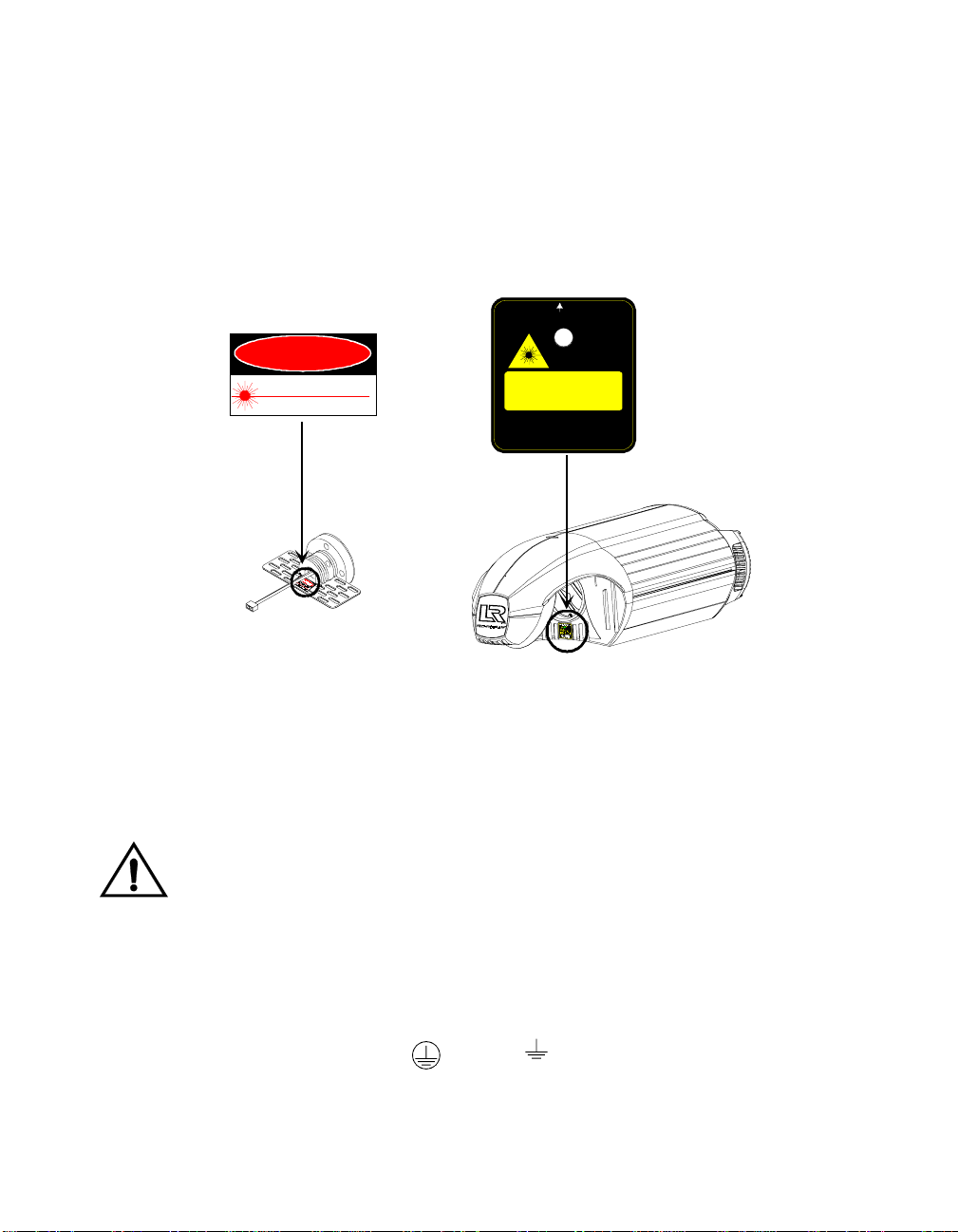
L AD Safety Standards
• EN60825-1, 1994
• 21 CFR 1040
AVOID EXPOSURE
Laser radiation is emitted from this aperture
Emission indicator
DANGER
LASER RADIATION - AVOID
DIRECT EYE EXPOSURE
Max output: 5mW at 630-650 nm
CLASS 3a LASER PRODUCT
Laser aiming device assembly
(inside fixture)
LASER RADIATION - DO NOT
STARE INTO BEAM OR
VIEW DIRECTLY WITH
OPTICAL INSTRUMENTS
Max output: 5mW at 630-650 nm
CLASS 3a LASER PRODUCT
Cert. to EN 60825-1, 1994
and 21 CFR 1040
Important Power Cord Information - U.K. Only
IMPORTANT
with the following code:
•
green and yellow:
•
blue:
•
brown:
This equipment must be earthed.
The cores in the mains lead are colored in accordance
earth
neutral
live
Vigtig Sikkerhedsin format ion - DANMARK
Advarsel: Beskyttelse mod elektrisk chock.
Vigtigt!
Lederen med gul/groen isolation maa kun tilsluttes en klemme maerket
eller
Technobeam® User Manual Specifications 1-3
Page 31

Dichroic, Litho and Effects Specifications
You can install any High End Systems-manufactured solid dichroic
filters, effects LithoPatterns lithos, ArtGlass, or Fusion Fire
as they were manufactured for use with Technobeam and not another
fixture; otherwise, the dichroics, lithos or effects might not fit in the
wheels properly.
You can also install gobos or lithos from other manufacturers as long
as they adhere to the following specifications:
Dichroics
• Diameter: 1.125” ± 0.010” (28.5 mm ± 0.25 mm)
• Thickness: 0.069” ± 0.010” (1.8 mm ± 0.25 mm)
Lithos
• Diameter/image area: 0.996”/0.860” ± 0.005” (25 mm/22 mm ±
0.13 mm)
• Maximum thickness (rotating litho only): 0.105” ± 0.005” (2.7
mm ± 0.13 mm)
• Thickness (static litho only): 0.069” ± 0.010” (1.8 mm ± 0.25
mm)
Rotating effects wheel
• Diameter/image area: 1.43”/1.04” ± 0.010” (36 mm/26 mm ±
0.25 mm)
• Maximum thickness: 0.175” ± 0.010” (4.4 mm ± 0.25 mm)
®
—as long
Safety Standards
Technobeam conforms to:
• EN 60598-1 : 1993
• EN 60598-2-17 : 1989
A1-A3 : 1993
• ANSI/UL-1572
• CAN/CSA C22.2 No. 9
Electromagnetic Standards
• EN 55022, Class A ITE
• IEC 801-2, 1991 Level 2 (4/8 kV)
• IEC 801-3, Draft 5 Level 2 (3 V/m)
• IEC 801-4, 1988 Level 2 (1 kV/0.5 kV)
1-4 Specifications Technobeam® User Manual
Page 32

Environmental Specifications
Maximum ambient temperature (Ta): 50° C (122° F)
Maximum exterior surface temperature: 70° C (158° F)
Minimum distance to flammable objects: 1.0 m (3.28 ft)
Minimum distance to lighted object: 1.0 m (3.28 ft)
DMX Data Cabling
•
DMX data cables:
specifications for EIA RS-485 applications) with characteristics
listed below:
• 2-conductor, twisted pair plus a shield
• maximum capacitance between conductors - 30 pF/ft.
• maximum capacitance between conductor & shield - 55 pF/ft.
• maximum resistance of 20 Ω/1000 ft.
• nominal impedance 100–140
• 22–24 AWG with insulation having a dielectric rating of 300
volts or higher
•
DMX data connectors:
•
DMX data terminators:
terminator between pins 2 and 3 (see Figure 2-4 on page 2-6)
Belden® 9841 or equivalent (meets
3-pin male and female XLR connectors
Male XLR connector with 120 ohm
Controllers
Technobeam may be controlled with any of the following:
•The Status Cue
• The Technobeam LCD controller
• Another DMX 512-compatible controller
®
lighting system
Optional Accessories
Ω
Table 1-1 below shows the optional accessories for Technobeam,
available from your High End Systems
®
dealer/distributor:
Table 1-1. Optional Accessories
Name Part Number
Optional lens sets Call*
Replacement MSD 250-2 lamp Call*
Custom color wheel dichroic filters Call*
LithoPatterns Call*
Technobeam® User Manual Optional Accessories 1-5
Page 33

Table 1-1. Optional Accessories
Name Part Number
Effects Call*
Technobeam LCD controller 29020001
Laser Aiming Device for Technobeam only
Status Cue System Call*
Heavy duty 3-pin XLR cable (10’) 55050005
Heavy duty 3-pin XLR cable (25’) 55050006
Heavy duty 3-pin XLR cable (50’) 55050007
Heavy duty 3-pin XLR cable (100’) 55050008
Deluxe C-clamp 55000004
Galvanized safety cable 12040001
Lightwave Research Upload Dongle 26040002
†
- You must obtain the Laser Aiming Device from High End Systems
Customer Service; see “Contacting High End Systems” on page Intro-4.
*
- Contact either your High End Systems dealer/distributor, High
Call
End Systems Sales, or the High End Systems World Wide Web site.
†
Unpacking the Fixture
Unpack the Technobeam box and verify that the contents arrived
complete and without any damage.
29060002
Save the Shipping Materials
Do not discard
and packing materials are specifically designed to protect the product
during transport.
High End Systems, Inc. assumes no responsibility for products
damaged during transport. Therefore, you should return a product for
repair in its original shipping carton and packing materials.
Note
1-6 Unpacking the Fixture Technobeam® User Manual
the shipping carton and packing materials. The carton
Before sending anything to the factory, call your HES
dealer/distributor for a Return Material Authorization
(RMA) number. The factory cannot accept any goods
shipped without an RMA number.
Page 34

Inspecting the Contents
Carefully unpack the carton and inspect the contents for damage. If
any items in the list below are missing or damaged you must notify
both the shipping agent and your sales agent immediately.
• One Technobeam fixture.
• Separate yoke packaging: one yoke, two yoke slide bezels, two
allen screws, two T-handles.
Installing the Power Cord Cap
IMPORTANT
with the following code:
•
green and yellow:
•
blue:
•
brown:
In some cases, you must obtain and install a power cord cap before you
can connect your fixture to a power outlet. The type of power cord cap
you must obtain depends on the location in which you will use
Technobeam; different locations (even within the same country) might
have different power cord cap requirements.
Note
The cores in the mains lead are colored in accordance
earth
neutral
live
Because of the wide variety of power cord caps used
worldwide, High End Systems, Inc. cannot make specific
recommendations for the particular power cord cap you
should use. Contact a local authority if you are unsure
which type of power cord cap you need.
Important P ower Cord C ap Information - U.K. Only
Since the colors of the cores in the mains lead of this equipment may
not correspond with the colored markings identifying the terminals in
your plug, proceed as follows:
• The core which is colored green and yellow must be connected to
the terminal in the plug which is marked with the letter “E” or by
the earth symbol , or colored green or green and yellow.
• The core which is colored blue must be connected to the terminal
which is marked with the letter “N” or colored black.
Technobeam® User Manual Installi ng th e Powe r Cord Cap 1-7
Page 35

• The core which is colored brown must be connected to the terminal
which is marked with the letter “L” or colored red.
Class 1 equipment: This equipment must be earthed.
VIGTIG FIKKER HEDS INFORMATION DANMARK
Advarsel:
Lederne med gul/groen isolation maa kun tilsluttes en klemme maerket
Beskyttelse mod elektrisk chock.
Vigtigt!
eller
Installing the Yoke
You will need: one 1/4” allen wrench
This section explains how to install the moving-track yoke. You can
adjust the yoke however you want to distribute the weight of the
fixture. You can even slide the yoke all the way to the end of the
fixture to hang it straight down.
1. Identify the components shown in Figure 1-1:
Yoke
Yoke slide bezel
(1 on each side)
T-handle
(1 on each side)
Allen screw
(1 on each side)
Side handle
(loosen 2 allen
screws to move yoke)
Mounting holes
(2 on each side)
Figure 1-1. Identifying yoke components.
1-8 Installing the Yoke Technobeam® User Manual
Page 36

2. Use a 1/4” allen wrench to attach one allen screw to each side of the
fixture (but do not fully tighten it), as shown in Figure 1-2.
you place a yoke slide bezel between the yoke and each side of the
fixture.
Make sure
Figure 1-2. Installing the yoke on the fixture.
3. Manually screw one T-handle into each side of the fixture. Do not fully
tighten the T-handles.
4. If you want to reposition the yoke, use a 1/4” allen wrench to loosen
the allen screws on the side handles shown in Figure 1-1 on page 1-8.
5. After loosening the side handle allen screws, slide the yoke to the
desired position. If you want to hang the fixture straight down, see the
section titled “Hanging the Fixture Straight Down” on page 2-12 now.
6. Make sure the yoke is even (i.e., the same distance from the rear of the
fixture on both sides).
7. Securely tighten the four side handle allen screws (two on each side).
8. Tilt the fixture to the desired angle, then securely tighten the other
allen screws and T-handle.
Technobeam® User Manual Installing the Yoke 1-9
Page 37

Setting the Fixture Voltage
Technobeam is shipped from the factory set for 230V, 50Hz and offer
the following switch-selectable voltage/frequency settings:
230 V, 50 Hz 208 V, 60 Hz
100 V, 50 Hz 100 V, 60 Hz
120 V, 50 Hz 120 V, 60 Hz
The recommended fuse F3 for all voltages and frequencies is:
F3 -
250V, 6.3A, Slow Blow Only.
WARNINGS (1) Check the voltage setting before
proceeding with equipment setup!
(2) The information in this section is
intended to assist qualified service
personnel because this fixture is to be
serviced by qualified service personnel
(3) Disconnect power before re-lamping or
servicing.
only
.
(4) Replace fuses with specified type and
rating only.
1. Make sure the fixture is disconnected from the power outlet before
proceeding.
2. Lay the fixture on its back and locate the door retaining screw, as
shown in Figure 1-3. Loosen the screw and remove the access door.
1-10 Setting the Fixture Voltage Technobeam® User Manual
Page 38

Door retaining screw
Access door
Figure 1-3. Removing the door allows you to access the fixture’s voltage
selection switches, as well as wheels and optics.
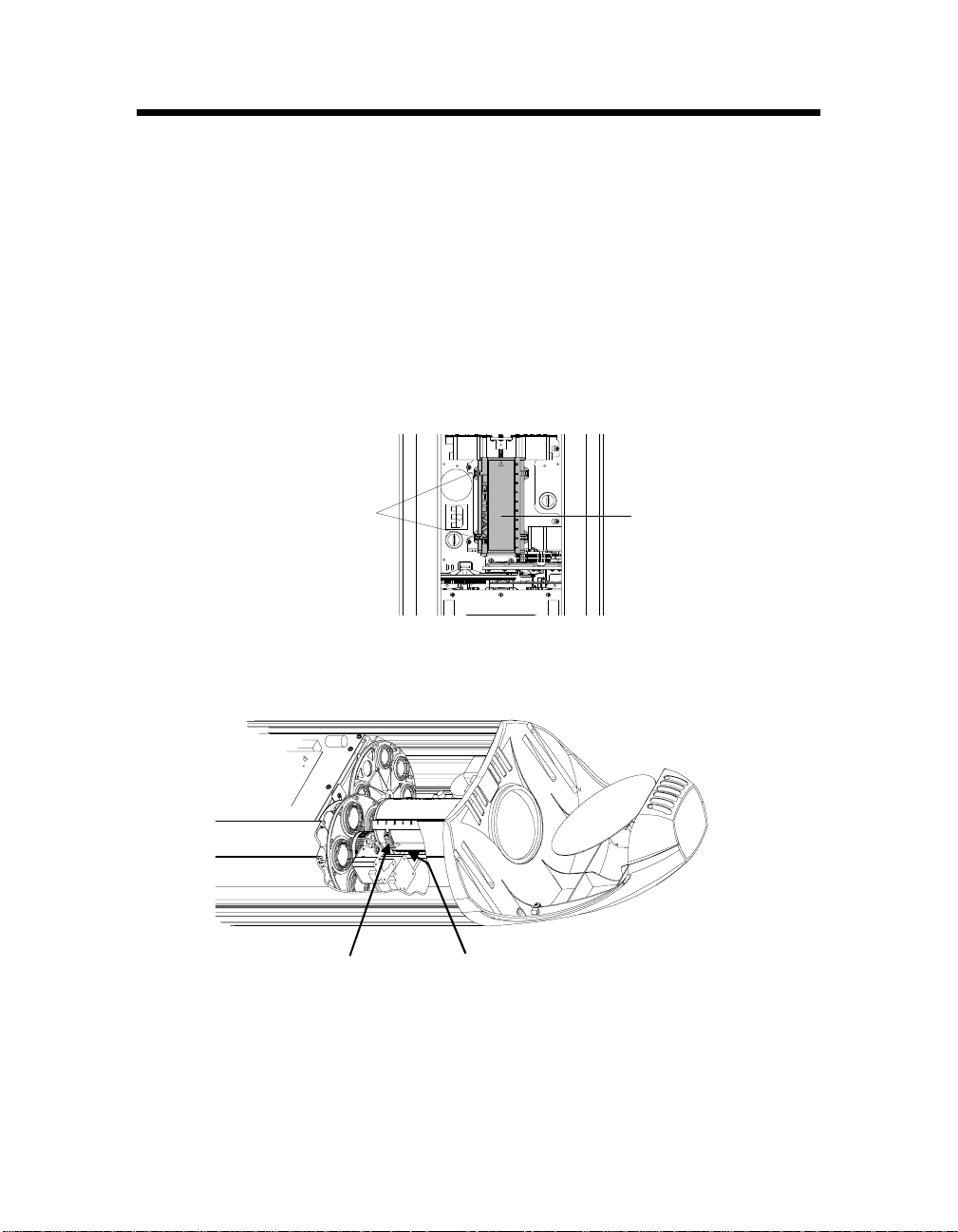
3. Locate the three switch blocks—labeled SW1, SW2 and SW3—by the LED
display, as shown in Figure 1-4:
Figure 1-4. The three voltage selection switches located next to the LED
display.
4. Choose a voltage/frequency setting as shown in Figure 1-5:
To p of
fixture
Figure 1-5. Setting the fixture’s voltage and frequency.
5. Replace the access door, unless you want to install the optional narrow
lens set or set the beam angle as shown in the next section.
Technobeam® User Manual Setting t he Fix ture Vo ltag e 1-11
Page 39
Setting the Beam Angle
This section explains how to set the fixture’s beam angle. (It also
shows how to install the optional 8 to 12 degree narrow angle lens set.)
You can change the beam angle, for example, if you are having trouble
focusing precisely on a very detailed image.
Selecting a larger beam angle results in a larger-diameter image, but
can also result in some loss of image resolution and light intensity.
Note
1. Unplug the fixture and remove the access door shown in Figure 1-3 on
page 1-11 if you have not done so already.
2. Lay the fixture on its back and locate the lens tube as shown in Figure
1-6.
Latches
(2 on each side)
Figure 1-6. The lens tube contains the zoom lenses.
3. The lens tube cover has two latches on each side that secure it in place;
see Figure 1-7. Squeeze the latches together to remove the lens tube
cover.
All beam angles are accurate to ±1°.
Lens tube
Squeeze latches
(2 on each side of
lens tube)
Figure 1-7. Squeeze the two latches on each side of the lens tube to open
the cover.
Focus drive screw
located under lens tube
(turn drive screw to move
lens tube for easier access)
1-12 Setting the Beam Angle Technobeam® User Manual
Page 40

Hint
e
If the latches are difficult to access, reach under the lens
tube and manually turn the focus drive screw to move
the lens tube toward the rotating effects wheel.
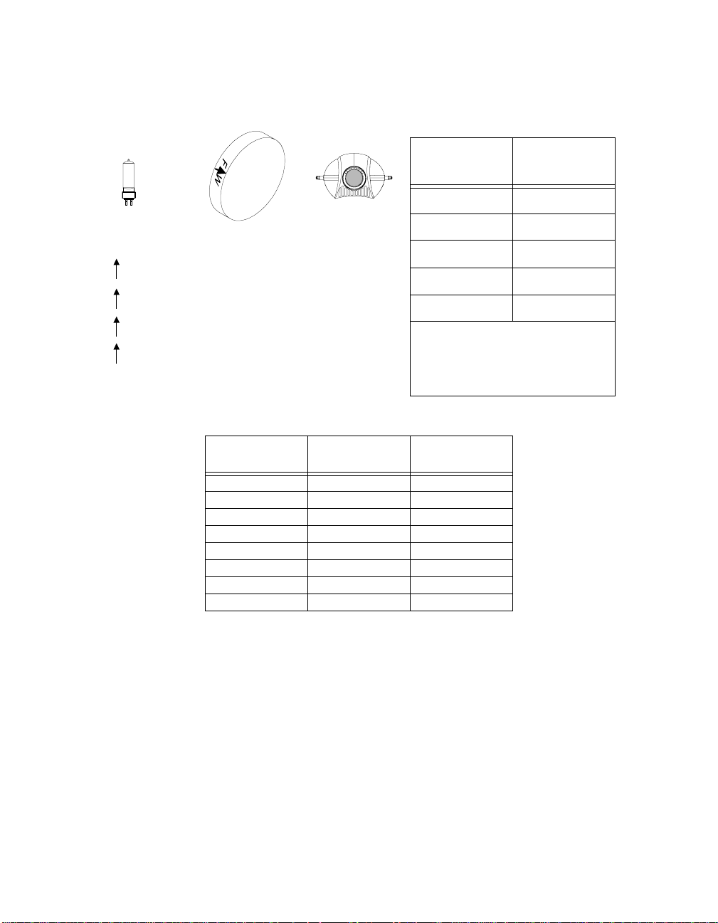
4. The factory-installed 11 to 17 degree lens set is shown Figure 1-8:
Lens tube cover
Rear lenses
(for 11 to 17
degree lens
set only)
Always leave
these lenses
in slot 1
Arrow points to
front of fixture
Front lens
Move this lens to cha ng
the beam angle
Figure 1-8. Components of the factory-installed 11 to 17 degree lens set.
5.
This step applies to the optional 8 to 12 degree narrow angle lens set
only.
a. Remove all lenses shown in Figure 1-8 and put them in a safe place
where they will not get scratched.
b. Use Table 1-3 on page 1-14 to install the two lenses in the 8 to 12
degree narrow angle lens set. The name and orientation of each
lens is printed on the side of the lens. The arrow printed on each
lens must point
toward the aperture
(i.e., away from the lamp).
6. Lens positions in the lens tube are numbered from 1 to 10, both on the
lens tube cover and on the bottom portion of the lens tube. Use those
numbers in either Table 1-2 on page 1-14 or Table 1-3 on page 1-14 to
move the lenses to correspond with the desired beam angle. The arrow
printed on the lens must point toward the front of the fixture (i.e.,
away from the lamp).
Caution Handle the lenses by the edge only.
Fingerprints can result in lower image
quality. Use only a soft, lint-free cotton
cloth to clean lenses. Use a mild glass
cleaning solution if necessary to clean builtup dust or dirt.
Technobeam® User Manual Setting the Beam Angle 1-13
Page 41
Lamp (arrow points
away from)
Aperture (arrow
points toward)
Table 1-2. Beam Angles for
Factory-Installed 11 to 17
Degree Lens Set
Beam Angle
11.5° 10
Front Lens
Position*
One of the following will be printed on each lens:
F W Front lens, factory-installed lens set
R W Rear lens, factory-installed lens set
F N Front lens, optional narrow angle lens set
R N Rear lens, optional narrow angle lens set
13.5° 8
15° 6
16.5° 4
17.5° 3
* - For the 11 to 17 degree lens
set, the rear lenses must always
be placed in slot 1 (see Figure
1-8 on page 1-13).
Table 1-3. Beam Angles for Optional 8 to 12 Degree Narrow Angle Lens Set
Beam Angle
8° 1 10
8.6° 2 10
9.1° 2 9
9.7° 2 8
10.3° 3 8
10.8° 3 7
11.4° 3 6
12° 3 5
7. When you are finished, replace the lens tube cover, making sure to
point the arrow on the cover toward the front of the fixture.
Rear Lens
Position
Front Lens
Position
1-14 Setting the Beam Angle Technobeam® User Manual
Page 42

Chapter 2 Setting Up Your Fixture
Powering On the Fixture .................................................................................2-2
Homing the Fixture .............................................................................2-2
LED Display ........................................................................................2-2
Status LEDs .........................................................................................2-3
Overview of Controller Operation ...................................................................2-4
What is DMX 512 Protocol? .................................................................2-4
What Kind of Cabling Should You Use? ..............................................2-4
Constructing Cabling .............................................................2-5
Terminators ...........................................................................2-5
Setting up the Link .............................................................................2-6
Linking the Fixtures to the Controller ............................................................2-7
Mounting the Fixture .......................................................................................2-8
Standing the Fixture on its End Handles ............................................2-9
Mounting the Fixture on a Truss or Other Support System ...............2-9
Hanging the Fixture Straight Down ................................................. 2-12
Configuring the Fixture ................................................................................ 2-13
Fixture Types ................................................................................... 2-13
Selecting a Control Method ............................................................. 2-14
DMX Start Channel Control Method .................................... 2-14
Fixture Number Control Method ......................................... 2-14
Assigning a Fixture Address ............................................................ 2-15
Channel Range .................................................................... 2-15
Determining the Unique DMX Start Channel ...................... 2-16
Determining the Unique Fixture Number ........................... 2-17
Wasted DMX Channels ........................................................ 2-17
Upgrading Software ...................................................................................... 2-18
Crossloading Software ..................................................................... 2-19
Troubleshooting ........................................................................................... 2-20
Troubleshooting DMX Data ............................................................. 2-24
Menu Error Messages ....................................................................... 2-25
Addr Lost ............................................................................ 2-25
Boot Diff ............................................................................. 2-25
EMEM Ack ............................................................................ 2-26
EMEM [message] .................................................................. 2-26
Erse Flsh ............................................................................. 2-26
ID Lost ................................................................................. 2-26
Lamp ................................................................................... 2-27
Link Busy ............................................................................ 2-27
Link Empty .......................................................................... 2-27
Over Temp .......................................................................... 2-28
PRST Lost ............................................................................ 2-28
PGRM Time .......................................................................... 2-28
Shut Down .......................................................................... 2-28
Technobeam® User Manual 2-1
Page 43

Powering On the Fi xt ure
Do all of the following before powering on the fixture:
1. Select the correct voltage and frequency settings for the power outlet
you will be using. See the section titled “Setting the Fixture Voltage” on
page 1-10.
2. Install the appropriate power cord cap as described in the section
titled “Installing the Power Cord Cap” on page 1-7.
3. Replace the access door shown in Figure 2-2 on page 2-3.
Homing the Fixture
Connect the fixture to an appropriately-rated power outlet; there is no
power switch. You will hear the sounds of the motors and gears as
they home.
LED Display
When the fixture has finished homing, the LED display should show the
fixture’s software version, similar to Figure 2-1:
This is normal
MENU ENTER
.
R
Figure 2-1. The initial LED menu display shows the fixture’s software
version.
Note
If the fixture fails to home, or if the menu displays an error message,
see the section titled “Troubleshooting” on page 2-20 now.
The LED display will alternate between the version
number (shown above) and the fixture number or DMX
start channel unless an error occurs during start-up.
2-2 Powering On the Fixture Technobeam® User Manual
Page 44

Status LEDs
Technobeam fixtures have three status LEDs located on the access
door, as shown in Figure 2-2:
Figure 2-2. Location of the three status LEDs on the fixture’s access door.
Door retaining screw
Access door
Table 2-1 describes the three status LEDs:
Table 2-1. Status LEDs
LED name State
Motor solid red No The motors are receiving adequate
OFF Yes Fuse or power failure. See below.
Transmit OFF Not necessarily* No data is being transmitted.
flickering yellow No A software crossload is taking place.
solid yellow Yes
Receive OFF Not necessarily* No data is being received.
flickering green No Fixture is receiving data.
If the LED states indicate a problem, see the section titled
“Troubleshooting” on page 2-20.
* - The Receive LED will not be ON unless the fixture is connected to a
DMX 512 link with a working controller. If you have already connected
Problem
Indication?
†
Description
voltage.
Software or hardware failure.
Technobeam® User Manual Powering On the Fixture 2-3
Page 45

the fixture to a controller and are sending DMX 512 commands to the
fixture, and the Receive LED is OFF, see the section titled
“Troubleshooting” on page 2-20.
† - Unless this fixture is crossloading, the yellow Transmit LED should
never be ON solid. (The Transmit LED will flicker yellow if you have
enabled preset playback
1 or DMX start channel 1. This is due to preset playback
synchronization, as described in “Synchronizing Preset Playback” on
page 4-9. Try unplugging the fixture, waiting a few minutes, then
plugging it back in. If the Transmit LED continues to be ON, contact
High End Systems Customer Service in one of the ways shown in the
section titled “Contacting High End Systems” on page Intro-4.
More information about crossloading software is shown in the section
titled “Upgrading Software” on page 2-18.
the fixture is set for either fixture number
and
Overview of Controller Operation
In order to coordinate the playback of multiple Technobeam fixtures
from a central location, you need to connect the fixtures to a DMX 512compatible controller using XLR data-grade cabling.
What is DMX 512 Protocol?
DMX 512 is an industry-standard protocol for controlling lighting
fixtures and other devices (such as lasers and hazers). Developed by
the United States Institute of Theatre Technology (USITT), DMX 512 is
supported by leading entertainment industry equipment
manufacturers.
DMX 512 (D for
channels per link) is a reliable, efficient and well-understood control
protocol. Its strength lies in its ability to control virtually any mix of
DMX-compatible devices on the same link using a DMX-compatible
controller.
digital, MX
for
multiplex
and
is the number of
512
What Kind of Cabling Should You Use?
There are two main types of cabling you can use: microphone cable
and data-grade cable. Although pin-compatible microphone cable is
suitable for small-scale designs, data cable is recommended, especially
for longer cable runs. Data cable is designed to carry a higher-quality
signal with less susceptibility to electromagnetic interference.
The cable you use should have the characteristics listed below:
• 2-conductor twisted pair plus a shield
• maximum capacitance between conductors - 30 pF/ft.
2-4 Overview of Controller Operation Technobeam® User Manual
Page 46

• maximum capacitance between conductor and shield - 55 pF/
ft.
• maximum resistance of 20 Ω/1000 ft.
• nominal impedance 100–140
• 22–24 AWG with insulation having a dielectric rating of 300
volts or higher
Ω
For example, Belden
EIA RS-485 applications and is highly recommended (or its equivalent)
for use with Technobeam.
Constructing Cabling
If you need to construct cabling, you must use a shielded, twoconductor cable with a male 3-pin XLR connector on one end and a
female 3-pin XLR connector on the other end. Pin 1 is the common
(cable shield), pin 2 is the data complement (negative), and pin 3 is the
data true (positive).
Figure 2-3. Properly-constructed data cabling.
®
9841 data-grade cabling meets specifications for
You should test each cable with a voltage/ohm meter (VOM) to verify
correct polarity and to make sure that the negative and positive pins
are not grounded or shorted to the shield or to each other. Also, make
sure that pin 1 is shielded.
Caution Do not connect anything to the ground lug
on the XLR connectors. Do not connect or
allow contact between the common (cable
shield) and the fixture’s chassis ground.
Grounding the common could cause a
ground loop and/or erratic behavior.
Terminators
The last device on each link must have a 120 ohm, 1/4 watt (minimum)
Technobeam® User Manual Overview of Controller Operation 2-5
Page 47

terminator attached to its Data Out connector.
You can construct terminators by following the instructions below:
1. Obtain a male XLR connector.
2. Disassemble the connector.
3. Solder a 120 ohm resistor, minimum
of 1/4 watt, between pins 2 and 3.
4. Reassemble the connector.
5. Install the terminator in the Data Out
port of the last device in the link.
Ω
0
2
1
Figure 2-4. Constructing a data cable terminator.
Setting up the Link
Follow the guidelines below when setting up the DMX link:
1. Do not allow the DMX channel ranges (boundaries) used by two
different devices on the link to overlap. Overlapping boundaries can
disable one or both devices. See Chapter 3 for more information about
channel boundaries for Technobeam. Consult the documentation
provided with the other devices for their DMX channel ranges.
2. You can assign two fixtures of the same type (for example, two
Technobeam fixtures both set to full protocol) to the same DMX
channel range if you want both fixtures to respond to control
commands in exactly the same way.
3.
Software uploads (updates):
non-High End Systems fixtures, optoisolators and serial data
distributors on the link if you want to perform software uploads or
crossloads as described in the section titled “Upgrading Software” on
page 2-18.
®
Dataflash
and Emulator
AF1000 xenon strobes, Intellabeam® automated luminaires,
®
laser simulators will stop software uploads to
Technobeam fixtures farther down the link. Make sure you put all of
the Intellabeam fixtures, Emulator fixtures and AF1000 fixtures
all of the Technobeam fixtures.
4. As long as you observe all of the rules above, you can use whatever
DMX channels and cabling scheme you want. You do not, for example,
have to assign the lowest DMX start channel to the fixture directly
connected to the controller. Use whatever channel and cabling scheme
is simplest and results in the least amount of cabling.
You must remove or bypass all controllers,
after
2-6 Overview of Controller Operation Technobeam® User Manual
Page 48
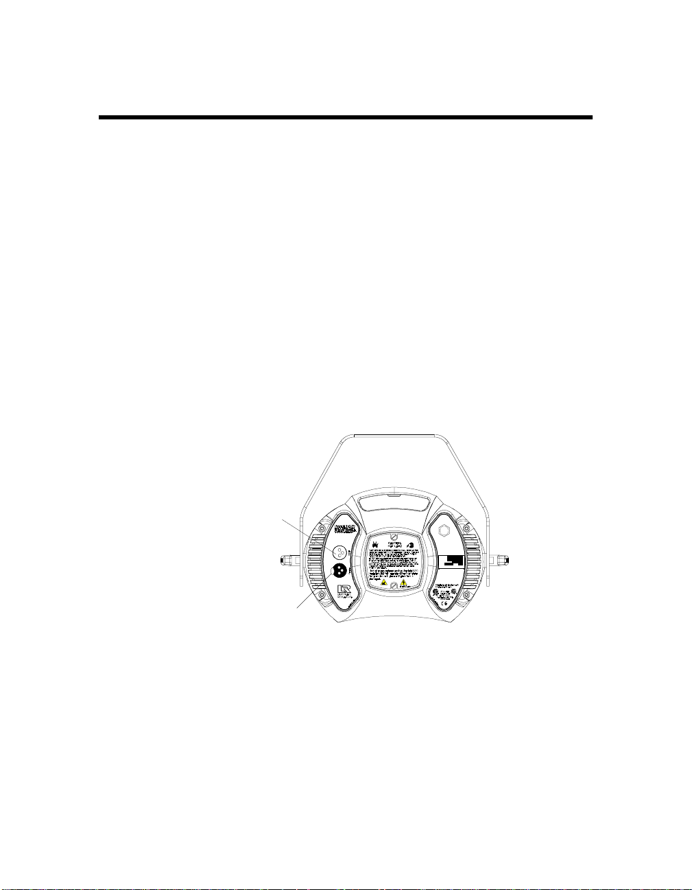
Linking the Fixtures to the Controller
Starting with the controller, link fixtures using the procedure below.
1. Consult the documentation provided with the controller for the
procedure to connect XLR cable to its Data Out connector.
2. Connect the female end of the XLR cable from the controller to the first
fixture’s male Data In connector.
3. Connect the male end of another XLR cable to the first fixture’s female
Data Out connector.
4. Continue connecting the Data Out connector from one fixture to the
Data In connector to the next fixture until you have linked all of the
Technobeam fixtures.
5. Connect other devices to the Technobeam fixtures as desired, using
the instructions in the documentation provided with those devices.
Place a male 120 ohm terminator on the female Data Out connector of
the last device in the link. The procedure for making a terminator can
be found in the section titled “Terminators” on page 2-5.
DMX data in (male)
TECHNOBEAM
MODEL
29FA000000
SERIAL
230V, 50Hz
FACTORY SET
1/28/98 TC
DATE
QC
Patents issued and pending. See user manual
for listings.
DMX data ou t (female)
Figure 2-5. Location of the DMX data in (male) and DMX data Out (female)
ports on the fixture’s rear panel.
Technobeam® User Manual Linking t he Fix ture s to the Co ntrol ler 2-7
Page 49

Data Out
Data In
Data Out
Data In
Controller
Data In
Data Out
Data In
Terminate the
Figure 2-6. Connecting fixtures to a controller. Make sure you terminate the
last fixture in the link.
Mounting the Fixture
You will need: - one 1/4” allen wrench
- clamps and safety cable as described in this
section
Your fixture is designed to be mounted in any orientation: you can
even hang it with its aperture pointing straight down or stand it on its
end handles. However you wish to mount the fixture, you must follow
the precautions and suggestions below:
• Verify the input voltage you are using matches the fixture’s voltage
selection switches (see the section titled “Setting the Fixture
Voltage” on page 1-10).
• Heed the warnings below to guard against personal injury and
damage to the fixture.
WARNINGS (1) This equipment for connection to a
branch circuit having a maximum overload
protection of 20 A.
(2) Class I Equipment - This fixture must be
earthed.
Data Out
2-8 Mounting the Fixture Technobeam® User Manual
Page 50

(3) Mount the fixtures and controllers in a
location that is away from direct heat and
protected from moisture. Do not mount on a
flammable surface.
(4) Maintain minimum distance of 1.0 meter
(3.28 feet) from combustible materials.
(5) Observe minimum distance to lighted
objects of 1.0 meter (3.28 feet). This means
the fixture must be positioned at least 1
meter away from the object it is
illuminating.
(6) Use a secondary safety cable when
mounting this fixture.
Standing the Fixture on its End Handles
The fixture’s end handles are designed to support its weight; however,
make sure you observe the following guidelines:
1. The fixture must be located away from moving objects that could
strike it and cause it to become unbalanced.
2. The fixture must be mounted on a sturdy, stable surface.
3. If the surface is above floor height, make sure you use safety cables as
described in the next section.
Mounting the Fixture on a Truss or Other Support System
If you are mounting the fixture on a truss or another type of support,
do all of the following:
1. Verify the truss or support will handle the weight of all the devices you
are mounting. Technobeam fixture weights are listed in the section
titled “Weight (including yoke)” on page 1-2.
2. The use of user-supplied safety cable is strongly recommended. You
must supply your own safety cable and you must verify the cable is
capable of supporting the weight of the fixture as listed in the section
titled “Weight (including yoke)” on page 1-2. You can order galvanized
safety cables from your High End Systems dealer/distributor (see
“Optional Accessories” on page 1-5).
3. You must supply your own clamps to attach the fixture to the support.
Verify that the clamp(s) you use are capable of supporting the weight
of the fixture as listed in the section titled “Weight (including yoke)” on
Technobeam® User Manual Mounting the Fixture 2-9
Page 51

page 1-2. You can order deluxe C-clamps for a two-inch truss from
your High End Systems dealer/distributor (part number 55000004).
Also see the section titled “Optional Accessories” on page 1-5.
o
4. Make sure the fixture
cannot
Allowing the fixture to rotate 360
be rotated all the way around (360
o
could loosen the clamp mounting
).
bolts.
Note
Because of the variety of conceivable lighting designs,
you should consider the procedure below as a
guideline
only. High End Systems, Inc. cannot make
suggested
specific recommendations for your particular lighting
design or venue.
Suggested mounting procedure:
1. Use two people to mount each fixture: one person to hold the fixture
while it is being secured in place, and one person to secure the fixture
to its support and to attach clamps and safety cables.
2. Always stand on a firm, stable surface when mounting a fixture to its
support. The fixture should be at a height where you can comfortably
work on it, and should either be resting on a stable surface or held in a
stable manner.
.
fixture
Do not allow one person to both support and mount the
3. Attach a suitable clamp through one of the holes on top of the yoke. If
you are attaching one clamp, use the middle hole on the yoke. If you
are attaching 2 clamps per fixture, attach one clamp to each of the
outer holes on the yoke.
attaching the clamp to the yoke
Use two locking washers per clamp when
.
Truss
Clamp securel y on truss
Use two (2) locking
washers
Insert bolt through hole in top of yoke
Figure 2-7. Use a locking washer when attaching a fixture to a truss.
2-10 Mounting the Fixture Technobeam® User Manual
Page 52

4. Tighten the clamp(s) firmly to the yoke and to the support.
5. Loop one or more suitable safety cables around the support and the
top of the yoke (see Figure 2-8).
Side view of yoke
Loop safety cable
through any of these
holes
TECHNOBEAM
MODEL
29FA000000
SERIAL
230V, 50Hz
FACTORY SET
1/28/98 TC
QC
DATE
Patents issued and pending. See user manual
for listings.
Figure 2-8. Always use a safety cable when mounting the fixture.
6. Loosen the T-handles on each side of the fixture (see Figure 2-9) and
orient the fixture to the desired tilt angle.
7. Tighten the T-handles to secure the fixture in the desired position.
8. When you have the fixture in the position you want, firmly tighten the
T-handles shown in Figure 2-9.
T-handle
Figure 2-9. Location of the T-handle you use to adjust the yoke position.
Technobeam® User Manual Mounting the Fixture 2-11
Page 53
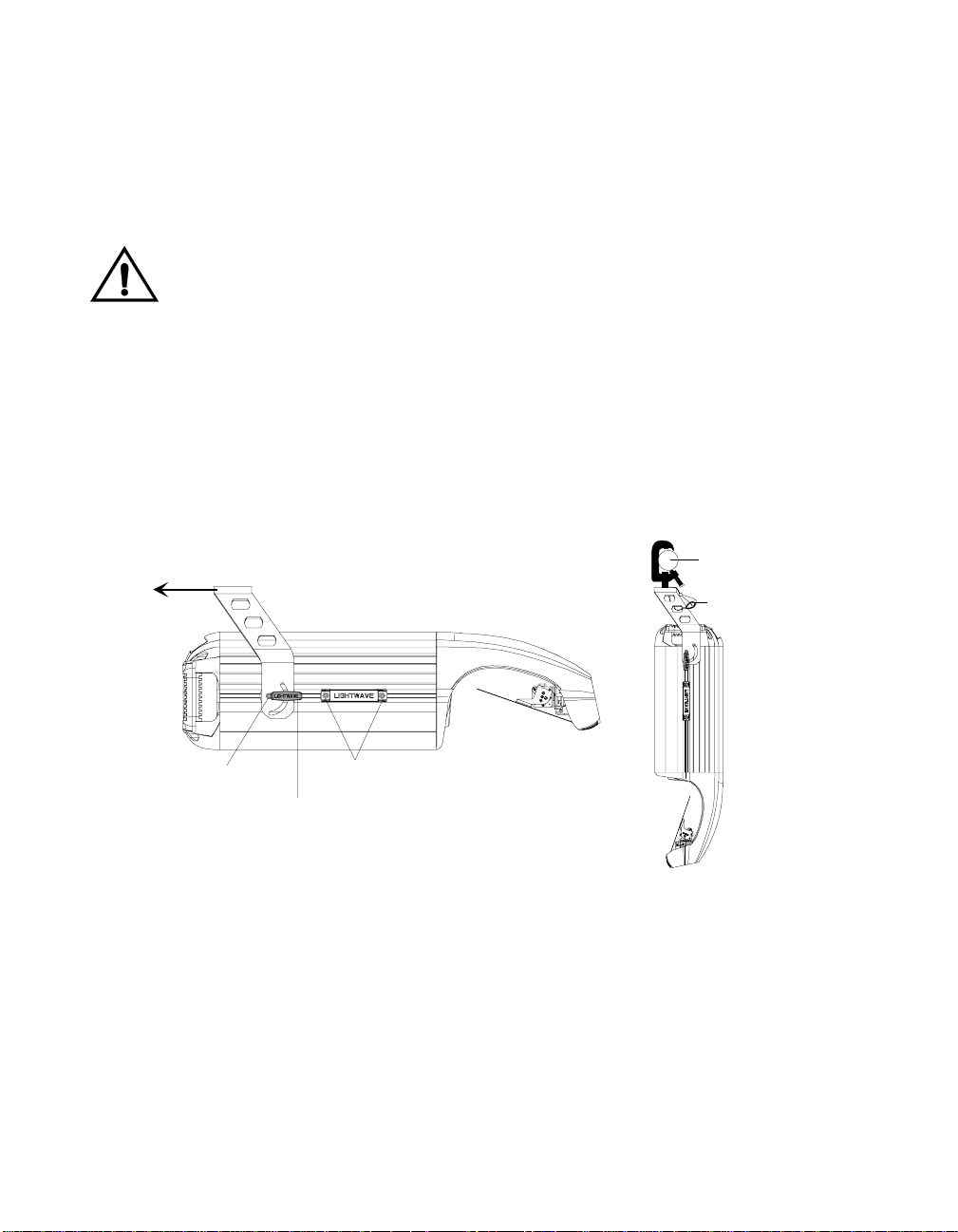
Hanging the Fixture Straight Down
Truss
Safety cable
You can mount Technobeam with the mirror head perpendicular to the
ground for projection onto a stage. This orientation also allows you to
economize truss space by hanging fixtures side by side close to each
other.
You must observe all of the precautions listed on the previous pages
regarding clamps and safety cables.
Caution You should adjust the yoke position while
the fixture is resting on a flat surface;
otherwise, the fixture may be damaged if it
slides backward.
1. Use a 1/4” allen wrench to loosen the two yoke allen screws (see Figure
2-10).
2. Use a 1/4” allen wrench to loosen the four handle allen screws (two on
each handle).
3. Slide the yoke to the rear of the fixture.
4. Loosen the T-handles on each side and rotate the yoke toward the rear
of the fixture.
Yoke allen screw
T-handle
Figure 2-10. You can slide the yoke all the way back to allow the fixture to
hang upside-down.
5. Tighten the allen screws and T-handles on both sides of the fixture,
then secure the fixture to the truss using a C-clamp with a locking
washer and safety cable as shown in Figure 2-10. When the fixture is
mounted like you want it, securely tighten the fixture’s T-handles.
Handle allen screws
2-12 Mounting the Fixture Technobeam® User Manual
Page 54

Configuring the Fixture
This section explains how to configure your fixture for operation by
selecting a fixture type and control method and assigning a fixture
address (either a DMX start channel or fixture number).
You must select a fixture type and control method and assign a fixture
address if you want to control the fixture with a DMX 512-compatible
controller. However, you can skip this section if you plan to use the
fixture in stand-alone mode (without a controller) and program the
fixture using preset programming, as shown in Chapter 3.
Configuring your fixture requires you to access the fixture’s menu
system via the alphanumeric LED display and four menu navigation
buttons on the fixture’s front panel (see Figure 2-11). For a detailed
description of the menu system, see “Using the Menus” on page 3-1.
alphanumeric LED display
MENU ENTER
<Up> arrow button: scroll upward
through menu items or options
<Down> arrow button: scroll downward
through menu items or options
<Menu> button: move back to the
previous menu level
(press and hold to enter the menu system)
Figure 2-11. Menu navigation buttons.
Fixture Types
Each fixture uses a fixture-specific protocol which determines the
number of DMX channels the fixture will use. To change the fixture
type, see “Setting the Fixture Type and Protocol (TYPE)” on page 3-15.
Available Technobeam fixture types and the number of DMX channels
used per fixture are listed below:
•
•
- Technobeam full protocol - uses 18 DMX channels per
TB F
fixture. The full protocol gives you more control over pan and tilt
position and litho spin speed and is for use with fixtures that
have an iris. You
not
the Laser Aiming Device™ (LAD™) or macros
- Technobeam reduced protocol - uses 14 DMX channels per
TB R
fixture. You should use this protocol if you need to conserve the
extra four DMX channels for other devices on the link, and your
fixtures
have an iris.
do not
<Enter> button: select the
curent menu item or option
select full protocol if you want to use
must
do
Technobeam® User Manual Configuring the Fixture 2-13
Page 55

•
•
- Technobeam iris protocol - uses 18 DMX channels per fixture.
TB I
This protocol should
- Technopro LCD protocol - uses 18 DMX channels per
TLCD
fixture. This protocol should
that are controlled with an LCD controller.
be used with fixtures that have an iris.
only
be used with Technopro fixtures
only
Selectin g a Control Method
You must select a control method for each fixture: either a DMX start
channel (recommended) or a fixture number (for a link with fixtures
that all use the same number of DMX channels).
Note
DMX Start Channel Control Method
If you plan to combine different types of devices (and/or protocols)
that use different numbers of channels on one DMX link, you should
use the DMX start channel control method. Using the DMX start
channel method to control your fixtures allows you to assign an
explicit start channel to each fixture, so no DMX channels are wasted.
For more information, see “Wasted DMX Channels” on page 2-17.
To select the DMX start channel control method:
1. Press and hold the <Menu> button until “ADDR” appears on the LED
display.
2. Using the <Up> and <Down> arrow buttons, scroll to the “SET” menu
and press the <Enter> button to select the “SET” menu.
3. Using the <Up> and <Down> arrow buttons, scroll to the “CHNL” menu
and press the <Enter> button to select the “CHNL” menu.
4. Using the <Up> and <Down> arrow buttons, scroll to the “DMX” option
and press the <Enter> button to select the “DMX” option.
Note
Once you choose a control method, you should use that
same control method for
You must select a control method for
fixture on the link.
the fixtures on a link.
all
Technobeam
each
Fixture Number Control Method
When you use the fixture number control method, each fixture “thinks”
all other devices on the link use the
it uses. Therefore, using the fixture number control method is a good
idea
DMX channels.
For example, assign fixture numbers if you have a link that
controls Technobeams set to iris protocol (or other devices that use 18
DMX channels), or a link that
protocol (or other devices that use 14 channels per link).
if you plan to link fixtures that all use the same number of
only
controls Technobeams set to reduced
only
2-14 Configuring the Fixture Technobeam® User Manual
number of DMX channels that
same
only
Page 56

To select the fixture number control method:
1. Press and hold the <Menu> button until “ADDR” appears on the LED
display.
2. Using the <Up> and <Down> arrow buttons, scroll to the “SET” menu
and press the <Enter> button to select the “SET” menu.
3. Using the <Up> and <Down> arrow buttons, scroll to the “CHNL” menu
and press the <Enter> button to select the “CHNL” menu.
4. Using the <Up> and <Down> arrow buttons, scroll to the “ADDR” option
and press the <Enter> button to select the “ADDR” option.
Note
You must select a control method for
fixture on the link.
Technobeam
each
Assigning a Fixture Address
The fixture’s address identifies each fixture’s channel range on the
DMX link. After you have selected a control method, you must assign a
DMX start channel or fixture number to each fixture:
• If you chose the DMX start channel control method for the fixture,
you must assign each fixture a DMX start channel.
• If you chose the fixture number control method, you must assign
each fixture a fixture number.
You must assign a
to respond
more fixtures to respond to controller commands in exactly the same
way, all fixtures must be the same type (for example two Technobeam
fixtures set to iris protocol) and must share the
independently
unique
fixture address to each fixture that you want
to controller commands. If you want two or
channel range.
entire
Channel Range
There are 512 available channels on each DMX link. These 512
channels are divided among
number of channels each fixture requires is called the fixture’s channel
range. The size of each fixture’s channel range is determined by the
fixture type (see “Fixture Types” on page 2-13).
Each Technobeam set to full, iris, or LCD protocol reserves a block of
18 contiguous channels. Each Technobeam set to reduced protocol
reserves a block of 14 contiguous channels. Therefore, you can control
up to 28 Technobeam fixtures set to full, iris, or LCD protocol (512
DMX channels available / 18 channels used = 28.4 fixtures per link) or
up to 32 Technobeam fixtures set to reduced protocol*.
*
Note
Although there are enough available DMX channels to
link up to 36 Technobeam fixtures in reduced protocol,
you must use a DMX splitter to connect more than 32
fixtures per link. The 32 device limit complies with the
EIA-485 standard. Connecting more than 32 devices per
Technobeam® User Manual Configuring the Fixture 2-15
the devices in a particular link. The
all
Page 57

link without a DMX splitter will eventually deteriorate
the digital signal.
The fixture’s channel range must not overlap any other device’s
channel range on the link. When two devices on the same DMX link
have overlapping channel ranges, one or both devices will be disabled
or behave erratically.
Note
The single exception to the non-overlapping rule is if the
fixtures are the same type (for example two
Technobeams set to iris protocol) and share the
channel range.
Determining the Uniqu e DMX Start Channel
The DMX start channel is the first channel available to a fixture in its
channel range. To determine each fixture’s DMX start channel in a link,
you must know the number of DMX channels used by each fixture (see
“Fixture Types” on page 2-13).
Knowing that the first fixture on the link will use DMX start channel 1,
you can determine the DMX start channel for each successive fixture by
adding the number of DMX channels used by the fixture to the fixture’s
DMX start channel. For example, in Table 2-2, 18 (channels used by the
Technobeam set to iris protocol) + 1 (DMX start channel for the first
fixture) = 19 (DMX start channel for the next fixture on the link).
Table 2-2. Example: Determining the DMX Start Channel
entire
Fixture
location on
Fixture name
the link*
First
Second
Third
Fourth
Fifth
1. Press and hold the <Menu> button until “ADDR” appears on the LED
Technobeam
(iris protocol)
Technobeam
(full protocol)
Technobeam
(reduced protocol)
Other Device
(using 12 channels)
Technobeam
(iris protocol)
*
Note
To assign a unique DMX start channel for the fixture:
display.
The fixture location on the link does not have to comply
with this example. The fixtures can be addressed in any
order on the link.
Number of DMX
channels used
per fixture
18 channels C001 1-18
18 channels C019 19-36
14 channels C037 37-50
12 channels C051 51-62
18 channels C063 63-80
DMX start
channel
Channel
range used
2-16 Configuring the Fixture Technobeam® User Manual
Page 58
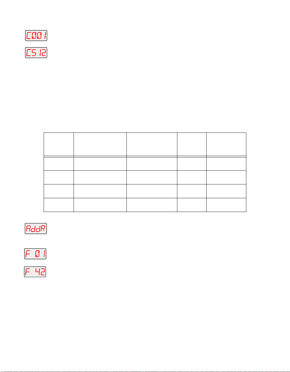
2. Press the <Enter> button to enter the “ADDR” menu.
3. Using the <Up> and <Down> arrow buttons, scroll to the desired DMX
t
start channel and press the <Enter> button to select the desired DMX
start channel.
Note
You must assign a unique fixture address to
Spot 250 or Studio Color 250 fixture that you wish to
respond independently to controller commands.
each
Determining the Unique Fixture Number
The fixture number is a number you assign that represents each
unique fixture’s channel range in the DMX 512 link. If you are using
one DMX link to control fixtures which all use the same number of DMX
channels (as recommended), you can assign fixture numbers in
ascending order (see Table 2-3).
Table 2-3. Example: Determining the Unique Fixture Number
Studio
Fixture
location
Fixture name
on the link
First
Second
Third
Fourth
1. Press and hold the <Menu> button until “ADDR” appears on the LED
2. Press the <Enter> button to enter the “ADDR” menu.
3. Using the <Up> and <Down> arrow buttons, scroll to the desired
t
Technobeam
(iris protocol)
Technobeam
(iris protocol)
Technobeam
(full protocol)
Other device
(using 18 channels)
To assign a unique fixture number to your fixture:
display.
fixture number and press the <Enter> button.
Note
You must assign a unique fixture address to
Technobeam fixture that you wish to respond
independently to controller commands.
Number of DMX
channels used
per fixture
18 channels F 01 1-18
18 channels F 02 19-36
18 channels F 03 37-54
18 channels F 04 55-72
Fixture
number
Wasted DMX Channels
If you mix different types of devices (which use different numbers of
channel ranges) on the same DMX link and assign fixture numbers
(instead of DMX start channels) to these devices, you would waste DMX
channels.
Channel
range used
each
Technobeam® User Manual Configuring the Fixture 2-17
Page 59

For example, in Table 2-4, if you assigned fixture number 2 (F 02) to the
Technobeam set to reduced protocol, it would assume that all other
fixtures on the link are also using 14 DMX channels, so it will
erroneously try to receive channel 15 as the first channel in its channel
range. This would create channel overlapping because fixture number
1 (Technobeam iris protocol) is already using channel 15 in its 18channel range.
In this example, to prevent overlapping channels, you must assign
fixture number 3 (F 03) to the Technobeam (reduced protocol), even
though it is physically the second fixture on the DMX link. While this
would prevent overlapping channels, it would result in wasted
channels that could not be used (see Table 2-4).
Table 2-4. Example of Wasted DMX Channels
Fixture
location
on the
link
First
Second
Third
Fourth
Therefore, if you choose to assign fixture numbers to different types of
devices (and/or protocols) on the same DMX link, refer to “Fixture
Number to DMX Start Channel” on page A-16, which shows the channel
ranges reserved for each Technobeam fixture type. This table will help
you determine the next available DMX start channel/fixture number for
successive Technobeam fixtures on the link.
Fixture name
Technobeam
(iris protocol)
Technobeam
(reduced protocol)
Technobeam
(iris protocol)
Technobeam
(reduced protocol)
Number of DMX
channels used
per fixture
18 channels
14 channels
18 channels
14 channels
Upgrading Software
Fixture number:
DMX channel range
used (to prevent
overlapping)
: 01-18
F 01
: 29-42
F 03
: 55-72
F 04
: 85-98
F 07
Resulting
channels
wasted
11 channels
wasted
(19-29)
13 channels
wasted
(43-54)
12 channels
wasted
(73-84)
There are three ways you can upgrade the
operational code) to Technobeam fixtures attached to a DMX link:
•
Uploading software from Status Cue.
updated software from High End Systems or a dealer/distributor.
Consult the
Status Cue User Manual
software
for instructions on uploading.
(fixture-specific
You will need to obtain
2-18 Upgrading Software Technobeam® User Manual
Page 60

•
Attaching a High End Systems upload dongle
. You will need an
upload dongle, 386-based (or faster) computer, MS DOS® version
3.3 (or later), and one MB of free disk space. To obtain an upload
dongle (with installation and operation instructions), contact your
HIgh End Systems dealer/distributor (see “Contacting High End
Systems” on page Intro-4).
•
Crossloading software between fixtures.
You will need one
Technobeam fixture with updated software and you can then load
the software across the DMX link to all other Technobeam fixtures
on the same link. For more information on crossloading software,
see the next section.
Crossloading Sof tware
The procedure that follows assumes you already have some familiarity
with the menu system; if not, see Chapter 3 and the menu map located
inside the back cover of this manual.
1. Remove or bypass all controllers, non-High End Systems fixtures,
optoisolators or serial data distributors on the link. These devices will
prevent crossloading.
2. If there are any Dataflash AF1000 xenon strobe fixtures, Emulator laser
simulators or Intellabeam automated luminaires on the same link,
make sure they are all
must bypass all AF1000s, Emulators or Intellabeams until the upload is
complete.
3. Determine which Technobeam fixture has the newest software. Skip to
Step 4 if you already know the software version on all your fixtures.
a. Navigate to the
INFO
b. Press <Enter> then use the <Up> or <Down> arrow keys to navigate
to the
VER
option.
c. Press <Enter>; the fixture’s software version will be displayed
similar to Figure 2-12:
all of the Technobeam fixtures. If not, you
after
menu.
R
MENU ENTER
Figure 2-12. This fixture has software version 3.
4. Once you are sure which fixture has the newest software (the
crossloading
fixture until the
5. Use the <Up> or <Down> arrow keys to navigate to the
fixture), press and keep pressing the <Menu> key on that
option is displayed.
ADDR
menu.
MODE
6. Press <Enter> and use the <Up> or <Down> arrow keys to navigate to
the
XLD
option.
Technobeam® User Manual Upgrading Software 2-19
Page 61

7. Press <Enter> to start the crossload. The Transmit LED on the
crossloading fixture will remain ON (or flicker) during the crossload.
The Transmit and Receive LEDs on other Technobeam fixtures on the
link will flicker while the crossload is in progress.
8. When the crossload has finished successfully, the following will
happen:
•
• All of the other Technobeam fixtures will home themselves.
9. Otherwise, if an error message is displayed, see the section titled
“Menu Error Messages” on page 2-25.
will appear briefly in the LED display of the crossloading
DONE
fixture, followed by MENU which will alternate with the fixture’s
fixture number or DMX start channel.
Troubleshooting
This section lists typical symptoms and solutions for problems you
might encounter when using your fixture. If you need additional help,
contact your dealer/distributor or High End Systems Customer Service
in one of the ways shown in the section titled “Contacting High End
Systems” on page Intro-4.
WARNING This information is intended to assist qualified
service personnel because this fixture is to be
serviced by qualified service personnel
only
.
Fixture does not work: no LEDs, fan, lamp, or other functionality
Possible causes and solutions:
1.
2.
Lamp does not strike
Possible causes and solutions:
1.
: No input power.
Cause
Solutions
a. Verify that the fixture is plugged into a working power supply.
b. Verify the integrity of the power cord and the wiring of the
Cause
Solution
Fuses” on page 6-2 to replace the necessary fuses.
Cause
Solution
a. Make sure the fixture is set for the same voltage as the power
: Do all of the following:
power cord cap as shown in the section titled “Installing the
Power Cord Cap” on page 1-7.
: One or more fuses have failed.
: Follow the directions in the section titled “Replacing
: Improper voltage setting or power cord cap wiring.
s: Do both of the following:
supply. See “Setting the Fixture Voltage” on page 1-10.
2-20 Troubleshooting Technobeam® User Manual
Page 62
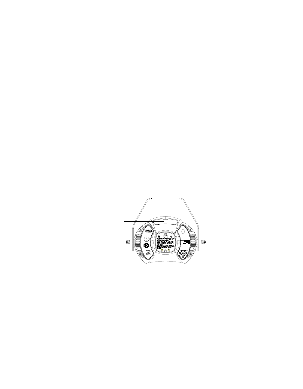
b. Make sure the power cord cap is wired correctly. See “Installing
the Power Cord Cap” on page 1-7.
2.
: One or more fuses have failed.
Cause
Solution
: Follow the instructions in the section titled “Replacing
Fuses” on page 6-2 to inspect the fuses and replace them if
necessary.
3.
: Bad lamp.
Cause
Solution
: Replace with a new or known good lamp.
Lamp shuts off
Possible causes and solutions:
1.
: Over-temperature. An over-temperature condition can be
Cause
confirmed by the message
display.
Solution
: See the section titled “Menu Error Messages” on page 2-
25.
2.
Fan has failed.
Cause:
Solution:
Home the fixture, either by unplugging the fixture and
plugging it back in, or by selecting
your hand over the exhaust vent shown in Figure 2-13. You should
feel a slight breeze from the fan. If not, the fan has failed. Contact
High End Systems Customer Service as shown in “Contacting High
End Systems” on page Intro-4.
OVER TEMP
HOME
on the fixture’s LED
from the Test menu. Put
Exhaust vent
MODEL
TECHNOBEAM
29FA000000
SERIAL
230V, 50Hz
FACTORY SET
1/28/98 TC
DATE
QC
Patents issued and pending. See user manual
for listings.
Figure 2-13. Location of the fixture’s exhaust vent.
3.
: Lamp socket is loose, causing arcing.
Cause
Solution
: Replace the lamp socket assembly. Call your High End
Systems dealer/distributor for more information.
4.
: Aging lamp.
Cause
Solution
: Replace with a new or known good lamp.
Technobeam® User Manual Troubleshooting 2-21
Page 63

Fixture is not responding to control commands—“Receive” LED does
not blink
Possible causes and solutions:
1.
2.
3.
Dim flags close, fixture does not respond to control commands, lamp
shuts off, fan turns off
: Faulty XLR cable.
Cause
Solutions
a. Replace XLR cables going to the fixture’s Data In and Data Out
b. Verify cable integrity using cable test equipment.
Cause
is not generating any output.
Solution
the controller is generating output by sending commands to a
known working device.
Also see the section titled “Troubleshooting DMX Data” on page 2-
24.
Cause
Solution
Fuses” on page 6-2 to inspect the fuses and replace them if
necessary.
: Do one or both of the following:
connectors with known good cables.
: There is no controller attached to the link, or the controller
: Verify that a controller is attached to the link. Verify that
: One or more fuses have failed.
: Follow the instructions in the section titled “Replacing
Possible causes and solutions:
1.
2.
Color wheel or litho wheel is not centered in the beam or is in the
wrong position
: Faulty XLR cable.
Cause
Solutions
a. Replace XLR cables going to the fixture’s Data In and Data Out
b. Verify cable integrity using cable test equipment.
c. See the section titled “Troubleshooting DMX Data” on page 2-
Cause
Solution
Fuses” on page 6-2 to replace the necessary fuses.
Cause:
specifications. A litho that is slightly under the recommended
thickness, for example, can turn in the wheel as the wheel rotates,
causing the litho to become uncentered.
: Do one or both of the following:
connectors with known good cables.
24.
: One or more fuses have failed.
: Follow the instructions in the section titled “Replacing
Non-High End Systems dichroic or litho does not meet
2-22 Troubleshooting Technobeam® User Manual
Page 64

Solution:
listed in the section titled “Specifications” on page 6-4.
Lithos or dichroic filters are cracking
Possible causes and solutions:
1.
Cause
Solution
a.
b.
c.
2.
Cause
Solution
scratches as shown in the section titled “Cleaning the Lenses and
Mirrors” on page 6-16.
3.
Cause:
Solution:
plugging it back in, or by selecting
your hands over the air exhaust shown in Figure 2-13 on page 2-21.
You should feel air movement. If not, the fan has failed. Contact
High End Systems Customer Service as shown in “Contacting High
End Systems” on page Intro-4.
Make sure all dichroics and lithos meet the specifications
: Improper installation.
:
General:
meet the specifications shown in the section titled
“Specifications” on page 6-4.
Lithos:
away from
toward
textured side away from the lamp and the flat side toward the
lamp.
Color wheel dichroic filters:
oriented with the coated side facing
glass (uncoated) side facing
page 6-6 shows how to tell which side is which.
: Faulty hot mirror allowing overheating inside the fixture.
Fan has failed.
Make sure you are using dichroics and lithos that
Lithos must be oriented with the coated side facing
the lamp and the glass (uncoated) side facing
the lamp. In the case of textured lithos, face the
: Visually inspect the hot mirror for cracks or deep
Home the fixture, either by unplugging the fixture and
Dichroic filters should be
toward
away from
HOME
the lamp and the
the lamp. Figure 6-5 on
from the Test menu. Put
Other components cracked or heat damaged
Possible causes and solutions:
1.
2.
: Faulty hot mirror allowing overheating inside the fixture.
Cause
Solution
scratches (see “Cleaning the Lenses and Mirrors” on page 6-16).
Cause:
Solution:
plugging it back in, or by selecting
your hands over the air exhaust shown in Figure 2-13 on page 2-21.
You should feel a slight breeze from the fan. If not, the fan has
failed. Contact High End Systems Customer Service as shown in
“Contacting High End Systems” on page Intro-4.
: Visually inspect the hot mirror for cracks or deep
Fan has failed.
Home the fixture, either by unplugging the fixture and
HOME
from the Test menu. Put
Technobeam® User Manual Troubleshooting 2-23
Page 65

Fixture will not accept software upload or crossload
Possible causes and solutions:
1.
2.
Low light output, fuzzy images
Possible causes and solutions:
1.
2.
3.
: Incorrect Status Cue configuration.
Cause
Solution
selecting the correct fixtures to upload, that you have the correct
software file, and are using the correct DMX channels for the
fixtures.
Cause
for all fixtures on the link when you are trying to perform the
crossload or upload).
Solution
fixtures, Emulator fixtures, non-High End Systems fixtures,
optoisolators or serial data distributors. These devices stop the
communication required for software crossloads or uploads. See
the section titled “Setting up the Link” on page 2-6 for more
information.
Cause:
Solution: Make sure you have installed the lenses in the correct
orientation, as shown in the section titled “Setting the Beam Angle”
on page 1-12.
Cause
Solution
Cause
Solution
glass as shown in the section titled “Cleaning the Internal
Components” on page 6-15.
: Consult the
: No return communication (indicated by Transmit LEDs OFF
: Make sure you bypass any AF1000 fixtures, Intellabeam
Incorrect lens installation.
: Aging lamp.
: Replace the lamp with a new or known good lamp.
: Dirty optical path.
: Clean all lenses, filters, lithos and the anti-reflective
Status Cue User Manual
to make sure you are
Troubleshooting DMX Data
This section explains how to use the DMX diagnostics built into
Technobeam to isolate the origin of data problems either in the fixture
or in the DMX 512 link. The instructions in this section should be
followed
protocol and the fixture’s menu system.
If you are having trouble with a fixture(s) on your DMX 512 link, you
should first review the following:
1. Are DMX 512 control commands being “misinterpreted” by the fixture?
If so, make sure the controller is configured for the correct fixture
type. For example, if you have a Technobeam set for full, 18-channel
2-24 Troubleshooting Technobeam® User Manual
by people with a good understanding of DMX 512
only
Page 66

protocol, but the controller is sending Technoray channel values, none
of the values you send from the controller will have the expected
effect. Continuing the same example, sending a value on channel 8
(which is effect wheel spin speed for Technoray) will result in selecting
a rotating litho wheel position on Technobeam.
2. Is more than one device affected? If so, and the devices are addressed
sequentially on the link, check to make sure addressing was done
properly on all affected devices. In particular, if you are using fixture
numbering, review the DMX channel boundaries for all affected
fixtures. Table A-5 on page A-16 shows fixture number to DMX channel
boundaries for Technobeam.
3. Make sure the last device on the link is terminated.
4. Are the gears and motors moving at all? If not, check for a loose cable
connection or a cable break somewhere on the link. If possible, verify
cable integrity or replace questionable cable with known good cable.
5. Make sure the controller is generating output. Consult the
documentation provided with the controller for more information.
6. Verify the DMX data for other fixtures on the link (see “Viewing DMX
Status and Construct Values (FIXT)” on page 3-24 or “Viewing DMX Data
for Another Device (DATA)” on page 3-26).
Menu Error Messages
This section lists the possible error messages that can appear on the
fixture’s LED display, as well as suggested actions. If the suggested
action does not solve the problem or if you have additional questions,
contact High End Systems Customer Service in one of the ways shown
in the section titled “Contacting High End Systems” on page Intro-4.
Addr Lost
The fixture’s software was unable to retrieve the fixture number or
DMX start channel from non-volatile storage. Try unplugging the
fixture, waiting a short time, then plugging it back in. If this error
message reoccurs, contact High End Systems Customer Service in one
of the ways shown in the section titled “Contacting High End Systems”
on page Intro-4.
Boot Diff
(Boot difference error.) This message may occur after a software
upload or crossload if new boot software has been included in the
upload. Selecting
the boot software storage area, and correct the cause of this error
message.
Technobeam® User Manual Troubleshooting 2-25
from the Test menu will copy the new boot to
BOOT
Page 67

EMEM Ack
This error may occur during data storage when an attempted write has
taken too long. Attempt the operation again. If this message reoccurs,
contact High End Systems Customer Service in one of the ways shown
in the section titled “Contacting High End Systems” on page Intro-4.
EMEM [message]
(Memory error.) This error indicates the fixture was unable to retrieve
one of the following from non-volatile storage:
•CHNL
•DPLY
•FHRS
•
•LHRS
•L/ST
•MODE
•PERS
•PINV
•TINV
•S/DN
•SWAP
•
The most likely cause is that an electrical event occurred and either
interrupted data storage or caused the non-volatile memory to be
corrupted. Try restoring the lost items manually. If the problem
persists, contact High End Systems Customer Service in one of the
ways shown in the section titled “Contacting High End Systems” on
page Intro-4.
—the fixture’s DMX start channel.
—LED display status (on, off, dim).
—number of fixture operating hours.
—lens set selection (NORM for factory-installed or optional
LENS
narrow angle set, WIDE for optional wide angle lens set).
—number of lamp operating hours.
—lamp strikes.
—preset playback status (ON/OFF/SCN).
—the fixture’s protocol (e.g., Technobeam full protocol).
—pan invert status.
—tilt invert status.
—shutdown time.
—pan/tilt swap status.
—time base (seconds, minutes, hours) for preset playback.
TIMB
Erse Flsh
Occurs during a crossload when the time required to erase a fixture’s
memory is excessive. Remove the fixture from the link and contact
High End Systems Customer Service. You might need to restart the
crossload as well.
ID Lost
The system software was unable to read the fixture’s ID number
(fixture number or DMX start channel) from its non-volatile storage
area. Try unplugging the fixture, waiting a short time, then plugging it
back in. If this error message reoccurs, contact High End Systems
Customer Service in one of the ways shown in the section titled
“Contacting High End Systems” on page Intro-4.
2-26 Troubleshooting Technobeam® User Manual
Page 68

Lamp
The word LAMP can appear on the display in two situations: one is an
error; the other is normal.
•
•
Link Busy
Occurs when the crossloading fixture detects that some other source is
driving data on the link. For crossloads to work properly, you must
remove or bypass all of the following if they are on the same link:
• Serial data distributors
•Optoisolators
• Non-High End Systems fixtures
• Controllers
• AF1000, Emulator or Intellabeam fixtures: Placing all AF1000,
After removing the offending device(s) from the data link, attempt the
crossload again.
Normal:
strike the lamp during fixture reset and homing. This is normal.
Not normal:
probably an electrical event—the fixture’s operating code loses
track of the lamp status, the lamp will turn off and the word
“LAMP” will appear in the LED display. Allow the fixture 5 to 10
minutes to cool before trying to turn the lamp on again.
Emulator or Intellabeam fixtures
good way to do this.
LAMP will be displayed when the fixture attempts to
If the lamp is running, and for some reason—
all Technobeam fixtures is a
after
Link Empty
Occurs when the crossloading fixture fails to find any other
Technobeam fixtures. If there are indeed other fixtures on the link, a
communication failure has occurred.
Possible causes include:
1. A bad data cable between the crossloading fixture and the first fixture
on the data link. Verify cable integrity with cable test equipment or
replace with known good cabling.
2. See “Link Busy” above.
3. One or more fixtures are powered off. Connect all fixtures on the link
to appropriately-rated power outlets and try again.
4. If none of the above solves the problem, the most likely cause is that
an electronics failure has occurred in the data section of one of the
fixtures on the data link. Try powering off one fixture at a time and
attempting the crossload. If you can isolate the crossload problem to
one fixture in particular, remove that fixture from the link and contact
High End Systems Customer Service in one of the ways shown in the
section titled “Contacting High End Systems” on page Intro-4.
Technobeam® User Manual Troubleshooting 2-27
Page 69

Over Temp
The internal fixture temperature has exceeded the maximum allowable
temperature. The lamp and the motors will shut down.
1. The primary external cause is high ambient air temperature. The
fixture’s maximum ambient temperature rating is shown in the section
titled “Environmental Specifications” on page 1-5. Unplug the fixture
and wait 5 to 10 minutes for it to cool before plugging it back in.
2. If allowing the fixture to cool does not solve the problem, check to
make sure the fan is working. Home the fixture, either by selecting
from the Test menu, or by unplugging the fixture and plugging
HOME
it back in. Place your hand over the air exhaust shown in Figure 2-13
on page 2-21. You should feel air movement. If not, the fan has failed.
Contact High End Systems Customer Service in one of the ways shown
in the section titled “Contacting High End Systems” on page Intro-4.
3. If the fan is working, unplug the fixture and verify the voltage setting
matches the power supply as shown in the section titled “Setting the
Fixture Voltage” on page 1-10. If the voltage setting is correct, contact
High End Systems Customer Service in one of the ways shown in the
section titled “Contacting High End Systems” on page Intro-4.
PRST Lost
(Preset Lost.) Scenes (presets) stored in the fixture’s onboard sixteenscene memory were lost.
The causes and solution for this error are the same as for “EMEM
[message]”.
PGRM Time
Occurs during a crossload when a receiving fixture has exceeded the
maximum allowable programming time. The crossloading fixture will
make a number of attempts to send new program data to each of the
receiving fixtures. If the receiving fixtures fails to respond properly
after a number of programming attempts have been made, the
crossloading fixture will drop the offending fixture from the upload
list, and display this error message.
Remove one fixture at a time from the link and attempt the crossload
again until you can isolate the crossload problem to a particular
fixture. Contact High End Systems Customer Service in one of the ways
shown in the section titled “Contacting High End Systems” on page
Intro-4.
Shut Down
The fixture has received a Shutdown command from the controller and
has shut down; i.e., the lamp and motors have been turned off.
Homing the fixture will bring it out of shutdown.
2-28 Troubleshooting Technobeam® User Manual
Page 70

Chapter 3 Using the Menus
Menu System Overview ...................................................................................3-2
Navigation Buttons .............................................................................3-2
Accessing the Menu System ...............................................................3-2
Menu Map ........................................................................................................3-3
Menu Options ............................................................................................... 3-10
Address Menu (ADDR) ..................................................................... 3-10
Set Menu (SET) ................................................................................. 3-11
Setting Factory Defaults (FACT) .......................................... 3-11
Swapping Pan and Tilt (SWAP) ............................................ 3-12
Inverting Tilt (T/IN) ............................................................ 3-12
Inverting Pan (P/IN) ............................................................ 3-12
Changing the Display Output (DSPL) .................................. 3-13
Inverting LED Characters (D/IN) ......................................... 3-13
Changing the Control Method (CHNL) ................................ 3-13
Setting the Lamp Warning Message (LMPL) ......................... 3-14
Changing the Lens Setting (LENS) ....................................... 3-14
Mode Menu (MODE) .......................................................................... 3-15
Setting the Fixture Type and Protocol (TYPE) ..................... 3-15
Setting the User Type (USER) .............................................. 3-16
Copying User Presets (PRST) ............................................... 3-17
Copying User Settings (SETT) ............................................. 3-18
Copying User Presets and Settings (ALL) ............................ 3-18
Crossloading Fixture Software (XLD) .................................. 3-19
Test Menu (TEST) ............................................................................. 3-20
Homing the Fixture (HOME) ................................................ 3-20
Turning the Lamp On or Off (LAMP) ................................... 3-20
Copying the Boot Code (BOOT) ........................................... 3-21
Performing Self Tests (SELF) ............................................... 3-21
Placing the Fixture in Setup Mode (S/UP) ........................... 3-22
Testing the LED Display (DISP) ........................................... 3-22
Information Menu (INFO) ................................................................. 3-22
Viewing the Logic Board Temperature (TEMP) .................... 3-23
Viewing the Current Lamp Hours (L/HR) ............................ 3-23
Viewing the Current Fixture Hours (F/HR) .......................... 3-23
Viewing the Number of Current Lamp Strikes (L/ST) ......... 3-24
Viewing the Current Software Version (VER) ...................... 3-24
Viewing DMX Status and Construct Values (FIXT) ............... 3-24
Viewing DMX Data for Another Device (DATA) ................... 3-26
Viewing Sensor Information (SENS) .................................... 3-26
Resetting Fixture Hours (F/RS) ........................................... 3-27
Resetting Lamp Hours (L/RS) .............................................. 3-27
Preset Menu (PRST) .......................................................................... 3-28
Setting Preset Playback (PLAY) ............................................ 3-28
Editing or Creating an On-Board Memory Scene (EDIT) ...... 3-29
Copying an On-Board Memory Scene (COPY) ...................... 3-29
Capturing a Preset Scene (CAPT) ......................................... 3-29
Enabling the Preset Default (DFLT) ..................................... 3-30
Technobeam® User Manual 3-1
Page 71

Menu System Overview
The Technobeam menu system allows you to:
• Configure your fixture for operation (discussed in Chapter 2)
• Access fixture options such as homing the fixture, crossloading
software, and performing self tests (discussed in this chapter)
• Use preset programming to create, store, and play back scenes
from the fixture’s onboard memory (see Chapter 4)
Navigation Buttons
The navigation buttons on the fixture’s display panel allow you to
navigate through the onboard menu system. As you navigate the menu
system, the alphanumeric display will show the menu items you select
from the menu map.
alphanumeric LED display
<Up> arrow button: scroll upward
through menu items or options
<Down> arrow button: scroll downward
MENU ENTER
through menu items or options
<Menu> button: move up
to the previous menu level
(press and hold to enter
the menu system)
Figure 3-1. Technobeam navigation buttons.
The alphanumeric display will flash when a new option is
pressing the <Up> and <Down> arrow buttons), and will stop flashing
when a new option is
Note
Pressing the <Menu> button returns you to the previous option or
menu
without changing
If you do not press the <Enter> button, the new option
you selected will not be stored.
<Enter> button: select the
curent menu item or option
entered
(by pressing the <Enter> button).
the value of an option.
Accessing the Menu System
To access the menu system, press and hold the <Menu> key until
“ADDR” appears on the LED display. The menu system is protected
against inadvertent menu changes by requiring the <Menu> button to
be held for a few seconds before allowing entry to the menus.
To exit the menu system, you must keep pressing the <Menu> button
to back out of each menu level until “MENU” appears on the LED
display. “MENU” will be replaced, after a few seconds, with the default
alternating display of the fixture’s software version and the fixture
number/DMX start channel.
selected
(by
3-2 Menu System Overview Technobeam® User Manual
Page 72

Menu Map
A complete menu map and explanations of the Technobeam menu
options are listed in this section. See individual subsections in this
addendum for descriptions of each menu item.
Chapter 4 has more information about using the menus to program the
fixture’s sixteen onboard scenes (presets).
Note
If your Technobeam-i does not have an iris and/or Laser
Aiming Device™ (LAD®), the iris and LAD-related menu
items listed below will have no functionality.
Although Technopro and Technoray fixtures have been
discontinued, their menu options still exist in the
protocol, and are listed below.
Table 3-1. Technobeam Menu Map
Menu
Level 1
ADDR Fxx/Cxxx
SET
Menu
Level 2
FACT
SWAP
T/IN
P/IN
DSPL
D/IN
CHNL
LMPL
LENS
Menu
Level 3
ON set factory defaults on
OFF
ON set pan/tilt swap on
OFF set pan/tilt swap off
ON set tilt invert on
OFF set tilt invert off
ON set pan invert on
OFF set pan invert off
ON set LED display on
OFF set LED display off
DIM dim LED display
ON invert LED display orientation
OFF set normal LED display orientation
DMX set control method to DMX start channel
ADDR set control method to fixture number
ON enable lamp hour warning message
OFF disable lamp hour warning message
NORM factory lens or narrow angle lens setting
WIDE wide angle lens setting
NARW
Menu
Level 4
Menu
Level 5
Description
change the existing fixture number/DMX start
channel
set factory defaults off
Note: Selecting this option has no affect on
individual preset values.
standard or narrow angle lens setting that
increases the distance the lens tube can move
to allow for a greater throw distance
Note: This option is not for use with wide angle
lenses.
Technobeam® User Manual Menu Map 3-3
Page 73

Table 3-1. Technobeam Menu Map
Menu
Level 1
MODE
TEST
INFO
Menu
Level 2
TYPE
XLD
USER
HOME home the fixture
LAMP
BOOT copy the boot sector
SELF
S/UP
DISP self test the alphanumeric LED display
CODE Factory use only
TEMP view the fixture’s current internal temperature
L/HR view the current number of lamp hours
F/HR view the current number of fixture hours
L/ST view the current number of lamp strikes
VER view the fixture’s software version
Menu
Level 3
TB F Technobeam full protocol (uses 18 channels)
TB R
TR F T echnoray full protocol (uses 14 channels)
TR R
TPRO Technopro protocol (uses 12 channels)
TB I Technobea m-i (uses 18 channels)
TLCD
A user A settings
B user B settings
COPY
LOFF extinguish the lamp
L ON strike the lamp
ALL self test all constructs
PAN self test mirror pan movement
TILT self test mirror tilt movement
COL self test color wheel movement
LTO self test litho wheel movement
FX self test effects wheel movement
FCUS self test lens tube movement
IRIS self tes t iris movem e n t
SHUT self test shutter strobe movement
DIM self test shutter dim flag movement
SET
NOW
Menu
Level 4
PRST
SETT
ALL
Menu
Level 5
Technobeam reduced protocol (uses 14
channels)
Technoray reduced protocol (uses 12
channels)
Technopro used with an LCD controller (uses
18 channels)
crossload fixture software to all other
Technobeam, Technoray, and Technopro
fixtures on the link
A -> B copy user A pres ets to user B
B -> A copy user B pres ets to user A
A -> B copy user A settings to user B
B -> A copy user B settings to user A
A -> B copy user A pres ets and settings to user B
B -> A copy user B pres ets and settings to user A
place the fixture in setup mode for mechanical
homing
Note: When the display shows “SET NOW,”
mechanically home the fixture, then press any
key to exit this menu option.
Description
3-4 Menu Map Technobeam® User Manual
Page 74

Table 3-1. Technobeam Menu Map
Menu
Level 1
INFO
PRST PLAY
Menu
Level 2
DMX FIXT
DMX
SENS
F/RS
L/RS
UNUM Customer Service use only
Menu
Level 3
FIXT
DATA
LTR
LTO
COLR
FX
OFF set preset playback off
ON set preset playback on
SCN display which scene is currently playing
Menu
Level 4
BRKS
FE
OV view the number of DMX overruns
STRT view the DMX start code value
PANH view the DMX high resolution pan value
PANL view the DMX low resolution pan value
TLTH view the DMX high resolution tilt value
TLTL view the DMX low resolution tilt value
COLC view the DMX color wheel control value
COL view the DMX fixed color wheel position value
LTOC view the DMX litho wheel control value
LTO view the DMX litho wheel position value
LTR view the DMX litho rotation value
FCUS view the DMX lens tube position value
FX view the DMX effects wheel position value
FXR view the DMX effects wheel rotation value
IRIS view the DMX iris position value
SHUT view the DMX shutter strobe value
DIM view the DMX shutter dim flag value
MSPD view the DMX MSpeed time value
LAD
CNTL view the DMX control channel value
C001 C512
ON
OFF
ON the litho wheel sensor is not obstructed
OFF the litho wheel sensor is obstructed
ON the color wheel sensor is not obstructed
OFF the color wheel sensor is obstructed
ON the effects wheel sensor is not obstructed
OFF the effects wheel sensor is obstructed
Menu
Level 5
Description
view the number of framing errors with zero
data (DMX breaks)
view the number of framing errors with nonzero data
view the DMX Laser Aiming Device (LAD)
value
view the DMX data for the selected DMX
channel
Note: You can only view DMX channels lower
than the last channel in the viewing fixture’s
channel range.
the litho rotate (within the wheel) sensor is not
obstructed
the litho rotate (within the wheel) sensor is
obstructed
reset fixture hours to zero (press and hold the
<Enter> button until the display shows “0000”)
reset lamp hours to zero (press and hold the
<Enter> button until the display shows “0000”)
Technobeam® User Manual Menu Map 3-5
Page 75
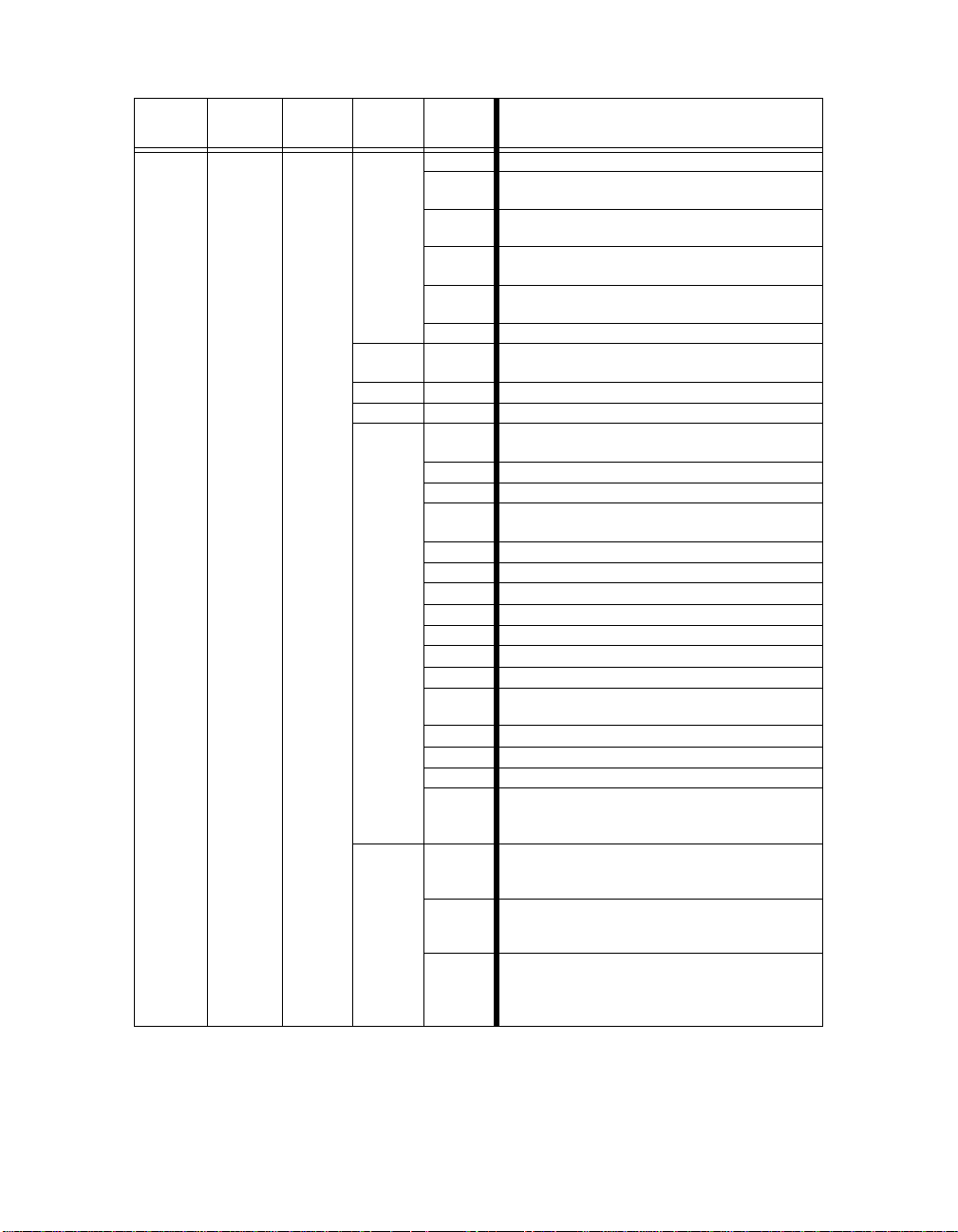
Table 3-1. Technobeam Menu Map
Menu
Level 1
PRST EDIT
Menu
Level 2
Menu
Level 3
SN01 SN16
Menu
Level 4
SHUT
DIM
PAN mirror pan from -89.9 to +89.9
TILT mirror tilt from -44.9 to +44.9
COLC
COL
Menu
Level 5
CLSD shutter closed
P 01 -
P 60
N 01 -
N 60
RS01 -
RS60
SR01 -
SR60
OPEN shutter open
D000 -
D255
IDX
FSP color wheel forward spin, full speed
RSP color wheel reverse spin, full speed
CON
SSC color wheel slow scanning, full speed
FSC color wheel fast scanning, full speed
RND color wheel random color positions, full speed
BLK color wheel blink selection, full speed
MIDX color wheel indexed position, MSpeed
MFSP color wheel forward spin, MSpeed
MRSP color wheel reverse spin, MSpeed
MCON
MSSC color wheel slow scanning, MSpeed
MFSC color wheel fast scanning, MSpeed
MRND color wheel random color positions, MSpeed
MBLK
C 1 C 13
HC 1 HC13
F000 F255
periodic shutter strobe at specified intervals,
slow (P 01) to fast (P 60)
random shutter strobe at random intervals,
slow (N 01) to fast (N 60)
shutter ramp open, slow (RS01) to fast (RS60),
snap shut
shutter snap open, ramp shut slow (SR01) to
fast (SR60)
select a dim value from dark (D000) to bright
(D255)
color wheel indexed position (wheel snaps to
center of color), full speed
color wheel continuously-variable position, full
speed
color wheel continuously-variable position,
MSpeed
blink selection (wheel snaps to center of color
and the shutter closes between positions),
MSpeed
select a full color position (only available if you
selected a COLC construct value of IDX or
MIDX)
select a half color position (only available if you
selected a COLC construct value of IDX or
MIDX)
select a forward color wheel spin speed from
none (F000) to fast (F255) (only available if
you selected a COLC construct value of FSP
or MFSP)
Description
3-6 Menu Map Technobeam® User Manual
Page 76

Table 3-1. Technobeam Menu Map
Menu
Level 1
PRST EDIT
Menu
Level 2
Menu
Level 3
SN01SN16
Menu
Level 4
COL
LTOC
LTO
Menu
Level 5
R000 R255
D000 D358
SC 1 SC26
FC 1 FC26
N000 N255
B 1 B 13
HB 1 HB13
IDX
FSP litho forward spin, full speed
RSP litho reverse spin, full speed
SC litho wheel scanning, full speed
BLK litho wheel blink selection, full speed
RND litho wheel random color positions, full speed
WSP litho wheel spin, full speed
MIDX litho wheel indexed position, MSpeed
MFSP litho forward spin, MSpeed
MRSP litho reverse spin, MSpeed
M SC litho wheel scanning, MSpeed
MBLK
MRND litho wheel random color positions, MSpeed
MWSP litho wheel spin, MSpeed
L 1 L 8
LF 1 LF 8
select a reverse color wheel spin speed from
none (R000) to fast (R255) (only available if
you selected a COLC construct value of RSP
or MRSP)
select a color wheel position in degrees from 0°
(D000) to 358° (D358) (only available if you
selected a COLC construct value of CON or
MCON)
slow scan of selected full color base position
(SC 1 - SC13) or half color base position
(SC14 - SC26) (only available if you selected a
COLC construct value of SSC or MSSC)
fast scan of selected full color base position
(FC 1 - FC 13) or half color base position
(FC14 - FC26) (only available if you selected a
COLC construct value of FC or MFC)
select a pause time between random color
wheel position changes, short (N000) to long
(N255) (only available if you selected a COLC
construct value of RND or MRND)
shutter blink on selected full color position (only
available if you selected a COLC construct
value of BLK or MBLK)
shutter blink on selected half color position
(only available if you selected a COLC
construct value of BLK or MBLK)
litho wheel indexed position (wheel snaps to
center of litho), full speed
litho wheel blink selection (wheel snaps to
center of litho and the shutter closes between
positions), MSpeed
select a litho wheel position (only available if
you selected a LTOC construct value of IDX or
MIDX)
select a forward spinning litho position (only
available if you selected a LTOC construct
value of FSP or MFSP)
Description
Technobeam® User Manual Menu Map 3-7
Page 77

Table 3-1. Technobeam Menu Map
Menu
Level 1
PRST EDIT
Menu
Level 2
Menu
Level 3
SN01SN16
Menu
Level 4
LTO
LTR
FCUS
FX
FXR
Menu
Level 5
LR 1 LR 8
SC 1 SC 8
B 1 B 8
RAND
WSPN
D000 D358
F000 F255
R000 R255
S000 S255
N000 N255
WF01 WF12
WR12 WR01
000 255
FX 1 FX 5
MFX1 MFX5
F001 F121
STIL effect does not spin
R001 -
R121
select a reverse spinning litho position (only
available if you selected a LTOC construct
value of RSP or MRSP)
scan selected litho base position (only
available if you selected a LTOC construct
value of SC)
select a litho wheel position (only available if
you selected a LTOC construct of BLK or
MBLK)
(because “Random” was selected for litho
control, no litho position can be assigned)
(because “Wheel Spin” was selected for litho
control, no litho position can be assigned)
select a litho angle from 0° (D000) to 358°
(D358) (only available if you selected a LTOC
construct value of IDX, BLK, MIDX, or MBLK)
select a litho’s forward spin speed from none
(F000) to fast (F255) (only available if you
selected a LTOC construct value of FSP or
MFSP)
select a litho’s reverse spin speed from none
(R000) to fast (R255) (only available if you
selected a LTOC construct value of RSP or
MRSP)
select a litho scan speed from slow (S000) to
fast (S255) (only available if you selected a
LTOC construct value of SC or MSC)
select a pause time between random litho
selections from long (N000) to short (N255)
(only available if you selected a LTOC
construct value of RND or MRND)
select a litho wheel forward spin speed from
slow (WF01) to fast (WF12) (only available if
you selected a LTOC construct value of WSP
or MWSP)
select a litho wheel reverse spin speed from
fast (WR12) to slow (WR01) (only available if
you selected a LTOC construct value of WSP
or MWSP)
select the lens tube position
select an effects wheel position, full speed
select an effects wheel position, MSpeed
select an individual effect’s forward spin speed
from fast (F001) to slow (F121)
select an individual effect’s reverse spin speed
from slow (R001) to fast (R121)
Description
3-8 Menu Map Technobeam® User Manual
Page 78

Table 3-1. Technobeam Menu Map
Menu
Level 1
PRST EDIT
Menu
Level 2
Menu
Level 3
SN01SN16
Menu
Level 4
IRIS
MSPD
XFAD
DLAY
MACR
TIME
ZERO OK
Level 5
OPEN fully open the iris
P 01 -
P 16
N 01 -
N 16
RS01 -
RS16
SR01 -
SR16
RR01 -
RR16
NR01 -
NR16
NS01 NS16
CLSD close the iris
I001 -
I127
0.15 -
252.7
X 0.1 -
X 9.9
X 10 -
X166
D 0.1 -
D 9.9
D 10 -
D166
MCOF set macro OFF
MC01 -
MC28
LROF set Laser Aiming Device (LAD™) OFF¹
LRON
LM01 LM30
SEC
MIN
HOUR
Menu
Description
select a speed to strobe the beam diameter,
from slow (P 01) to fast (P 16)
select a random frequency to strobe the beam
diameter, from less often (N 01) to more often
(N 16)
select the speed to ramp open, slow (RS01) to
fast (RS16), then snap shut
select the speed to snap open, then ramp shut
slow (SR01) to fast (SR16)
select the speed to ramp open, then ramp shut
slow (RR01) to fast (FF16)
select the random frequency to ramp open,
from less often (NS01) to more often (NS16),
then snap shut
select the random frequency to snap open,
then ramp shut from less often (NR01) to more
often (NS16)
select a beam diameter, from small (I001) to
large (I127)
select an MSpeed value in decimal seconds
from fast (0.15) to slow (252.7)
select the DIM and FCUS construct’s
crossfade time in increments of 0.1
select the DIM and FCUS construct’s
crossfade time in increments of 1
select the delay time in increments of 0.1
select the delay time in increments of 1
select a factory-programmed macro from 1 - 28
set Laser Aiming Device (LAD™) ON
continuously¹
select a LAD™ strobe speed from slow (4.25
per second - LM01) to fast (255 per second LM30)¹
select seconds as the units of time used for the
XFAD and DLAY constructs
select minutes as the units of time used for the
XFAD and DLAY constructs
select hours as the units of time used for the
XFAD and DLAY constructs
erase any programming of the current scene
by voiding all construct values / mark the end
of a loop
Technobeam® User Manual Menu Map 3-9
Page 79

Table 3-1. Technobeam Menu Map
Menu
Level 1
PRST
Menu
Level 2
COPY
CAPT
DFLT OK?
Menu
Level 3
FROM
TO
SN01 SN16
Menu
Level 4
FA01 FA16
FB01FB16
TA01 TA16
TB01
TB16
Menu Options
The sections below explain how to access the individual menu options
shown in the fixture’s menu map.
Address Menu (ADDR)
Use the Address menu to quickly change the current fixture number/
DMX start channel. Using this menu option, you can only change the
fixture number to another fixture number, or the
Be sure you do not overlap fixture channel ranges when
changing the fixture number/DMX start channel.
or
existing
start channel to another DMX start channel.
If you want to change the way you identify the fixture (i.e. change to a
fixture number instead of a DMX start channel, or vice versa), complete
the procedure described in “Changing the Control Method (CHNL)” on
page 3-13.
To change the current fixture number or DMX start channel:
1. Press and hold the <Menu> button until “ADDR” appears on the LED
display.
2. Press the <Enter> button to select the “ADDR” menu.
3. Use the <Up> and <Down> arrow buttons to select a new DMX start
channel (C001 - C512) / fixture number (F 01 - F xx). The LED display
will flash when a new option is selected.
4. Press the <Enter> button to accept the new fixture number / DMX start
channel. The LED display will stop flashing when a new option is
entered. If you do not press the <Enter> button, the new option you
selected will not be stored.
Note
Menu
Level 5
Description
select a scene to copy from (source scene) for
user A
select a scene to copy from (source scene) for
user B
select a scene to copy to (destination scene)
for user A
select a scene to copy to (destination scene)
for user B
select a scene to capture a pre-programmed
scene to (from your DMX controller)
enable the factory-programmed 16 preset
scene sequence - erases any preset scenes
previously programmed
existing
DMX
3-10 Menu Options Technobeam® User Manual
Page 80

Set Menu (SET)
The Set menu allows you to change the control method from a fixture
number to a DMX start channel or vice versa, and either set all factory
options to their default settings or change the factory options
individually. The procedures below are listed in the order that they
appear in the menu map.
Setting Facto ry Defaults (FACT)
Technobeam-i fixtures are shipped from the factory with the following
preset options set to the following defaults:
• Pan/tilt swap = off
• pan invert = off
• tilt invert = off
•preset playback = off
• LED display = on and bright
• LED display invert = off
• lamp hour warning = off
To return
5. Press and hold the <Menu> button until “ADDR” appears on the LED
display.
6. Using the <Up> and <Down> arrow buttons, scroll to the “SET” menu
and press the <Enter> button to select the “SET” menu.
7. Using the <Up> and <Down> arrow buttons, scroll to the “FACT” menu.
(This will be the first menu displayed.) Press the <Enter> button to
select the “FACT” menu.
8. Using the <Up> and <Down> arrow buttons, choose “ON” to set the
factory option defaults on and press the <Enter> button to select the
desired option.*
*Note
preset options to their factory defaults settings:
all
Although “OFF” is an available option in the FACT menu,
selecting the “OFF” option will have
individual preset values. To change the value of any of
the individual presets listed above, you must access
each preset’s corresponding menu item. When you
change any of the preset default values individually, this
menu item will
automatically
be turned off.
no effect
on the
Technobeam® User Manual Menu Options 3-11
Page 81
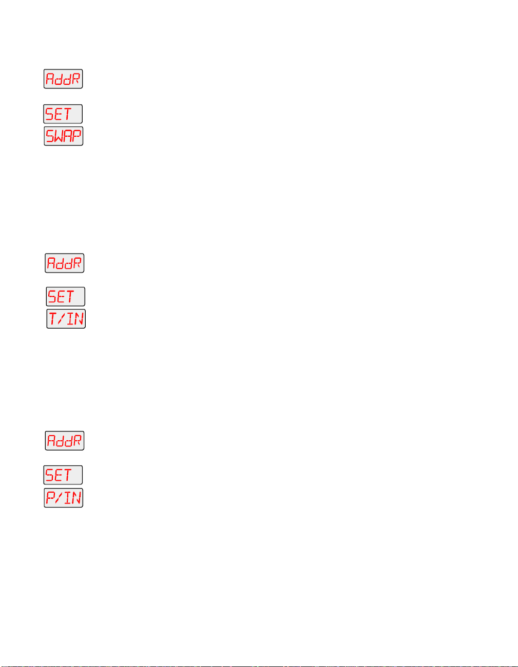
Swapping Pan and Tilt (SWAP)
To swap the fixture’s pan and tilt motion:
1. Press and hold the <Menu> button until “ADDR” appears on the LED
display.
2. Using the <Up> and <Down> arrow buttons, scroll to the “SET” menu
and press the <Enter> button to select the “SET” menu.
3. Using the <Up> and <Down> arrow buttons, scroll to the “SWAP” menu
and press the <Enter> button to select the “SWAP” menu.
4. Using the <Up> and <Down> arrow buttons, choose the “ON” option to
swap the fixture’s pan and tilt motion, or the “OFF” option to return the
fixture’s pan and tilt motion to their normal orientation. Press the
<Enter> button to select the desired option.
Inverting Tilt (T/IN)
To invert the direction of the fixture’s tilt motion:
1. Press and hold the <Menu> button until “ADDR” appears on the LED
display.
2. Using the <Up> and <Down> arrow buttons, scroll to the “SET” menu
and press the <Enter> button to select the “SET” menu.
3. Using the <Up> and <Down> arrow buttons, scroll to the “T/IN” menu
and press the <Enter> button to select the “T/IN” menu.
4. Using the <Up> and <Down> arrow buttons, choose the “ON” option to
invert the fixture’s tilt motion, or the “OFF” option to return the
fixture’s tilt motion to normal orientation. Press the <Enter> button to
select the desired option.
Inverting Pan (P/IN)
To invert the direction of the fixture’s pan motion:
1. Press and hold the <Menu> button until “ADDR” appears on the LED
display.
2. Using the <Up> and <Down> arrow buttons, scroll to the “SET” menu
and press the <Enter> button to select the “SET” menu.
3. Using the <Up> and <Down> arrow buttons, scroll to the “P/IN” menu
and press the <Enter> button to select the “P/IN” menu.
4. Using the <Up> and <Down> arrow buttons, choose the “ON” option to
invert the fixture’s pan motion, or the “OFF” option to return the
fixture’s pan motion to normal orientation. Press the <Enter> button to
select the desired option.
3-12 Menu Options Technobeam® User Manual
Page 82

Changing the Display Output (DSPL)
This menu item allows you to change the appearance of the fixture’s
alphanumeric LED display. You can set the display on or off, or you
can dim the display to reduce visibility.
To change the display output:
1. Press and hold the <Menu> button until “ADDR” appears on the LED
display.
2. Using the <Up> and <Down> arrow buttons, scroll to the “SET” menu
and press the <Enter> button to select the “SET” menu.
3. Using the <Up> and <Down> arrow buttons, scroll to the “DSPL” menu
and press the <Enter> button to select the “DSPL” menu.
4. Using the <Up> and <Down> arrow buttons, choose the “ON” option to
set the LED display to normal intensity, the “OFF” option to turn the
LED display off, or the “DIM” option to reduce the LED display visibility.
Press the <Enter> button to select the desired option.
Note
If you set the LED display off, the LED display will be
turned off only when you exit the menu system.
Inverting LED Characters (D/IN)
This menu item allows you to invert the orientation of the LED
display’s alphanumeric characters. This option is useful if your fixture
is standing upright (i.e., resting on its bottom panel on the floor).
To invert the LED display:
1. Press and hold the <Menu> button until “ADDR” appears on the LED
display.
2. Using the <Up> and <Down> arrow buttons, scroll to the “SET” menu
and press the <Enter> button to select the “SET” menu.
3. Using the <Up> and <Down> arrow buttons, scroll to the “D/IN” menu
and press the <Enter> button to select the “D/IN” menu.
4. Using the <Up> and <Down> arrow buttons, choose the “ON” option to
invert the fixture’s alphanumeric characters, or the “OFF” option to
return the fixture’s alphanumeric characters to normal orientation.
Press the <Enter> button to select the desired option.
Changing the Control Method (CHNL)
Use this menu item if your fixture is currently set to the fixture
number control method and instead, you want to use the DMX start
channel control method, or vice versa. To simply change an existing
fixture number to a different fixture number (or DMX start channel to a
different DMX start channel), see “Address Menu (ADDR)” on page 3-10.
Technobeam® User Manual Menu Options 3-13
Page 83

To change the control method:
1. Press and hold the <Menu> button until “ADDR” appears on the LED
display.
2. Using the <Up> and <Down> arrow buttons, scroll to the “SET” menu
and press the <Enter> button to select the “SET” menu.
3. Using the <Up> and <Down> arrow buttons, scroll to the “CHNL” menu
and press the <Enter> button to select the “CHNL” menu.
4. Using the <Up> and <Down> arrow buttons, choose either the “DMX”
or
option to address the fixture using a DMX start channel, or the “ADDR”
option to address the fixture using a fixture number. Press the
<Enter> button to select the desired option.
Note
After changing the control method, you must assign a
specific DMX start channel (C001 - C512) or fixture
number (F 01 - F xx) to each fixture (see “Address Menu
(ADDR)” on page 3-10).
Setting the Lamp Warning Message (LMPL)
Use this menu item to enable your fixture to display the warning
message “LAMP LIFE ERR” when the current lamp hours exceed 2,000.
With this option enabled, after the current lamp hours exceed 2,200
hours, the fixture will display the warning message “LAMP OUT ERR.”
Once the lamp is extinguished, the fixture will no longer strike the
lamp until the current lamp is replaced and the current lamp hours are
reset to zero (see “Replacing the Lamp” on page 6-11 or “Resetting
Lamp Hours (L/RS)” on page 3-27).
To enable the lamp warning message:
1. Press and hold the <Menu> button until “ADDR” appears on the LED
display.
2. Using the <Up> and <Down> arrow buttons, scroll to the “SET” menu
and press the <Enter> button to select the “SET” menu.
3. Using the <Up> and <Down> arrow buttons, scroll to the “LMPL” menu
and press the <Enter> button to select the “LMPL” menu.
4. Using the <Up> and <Down> arrow buttons, choose the “ON” option to
or
enable the lamp warning message, or the “OFF” option to disable the
lamp warning message. Press the <Enter> button to select the desired
option.
Changing the Lens Setting (LENS)
Use this menu item if you change the lenses in your fixture. Available
lens sets include standard, narrow angle, and wide angle lenses. To
obtain a different lens set, contact your High End Systems dealer/
distributor.
3-14 Menu Options Technobeam® User Manual
Page 84

To change the lens setting:
1. Press and hold the <Menu> button until “ADDR” appears on the LED
display.
2. Using the <Up> and <Down> arrow buttons, scroll to the “SET” menu
and press the <Enter> button to select the “SET” menu.
3. Using the <Up> and <Down> arrow buttons, scroll to the “LENS” menu
and press the <Enter> button to select the “LENS” menu.
4. Using the <Up> and <Down> arrow buttons, choose the “NORM” option
or
or
for standard or narrow angle lenses, the “WIDE” option for wide angle
lenses, or the “NARW” option for standard or narrow angle lenses with
increased lens tube travel for a greater throw distance.
Note
5. Press the <Enter> button to select the desired option.
The “NARW” option is
for use with wide angle lenses.
not
Mode Menu (MODE)
The Mode menu allows you to set the fixture type and protocol and
crossload software versions from one fixture to all other Technobeam-i
fixtures on the link. The procedures below are listed in the order that
they appear on the menu map.
Setting the Fixture Type and Protocol (TYPE)
Use this menu item to change the fixture type and protocol. The
protocol is specific to the fixture and determines the number of DMX
channels the fixture will use.
Note
Available protocols are listed below:
•
TB F
•
TB R
Although Technopro and Technoray fixtures have been
discontinued, their menu options still exist in the
protocol.
(Technobeam full protocol) - for use with Technobeam
fixtures without an iris. This protocol uses 18 DMX
channels and is recommended, unless you need to
conserve the extra four DMX channels for other devices on
the link. The full protocol gives you more control over pan
and tilt position and litho spin speed. This protocol allows
you to access the Laser Aiming Device™ (LAD) or macros.
(Technobeam reduced protocol) - for use with Technobeam
fixtures only. This protocol uses 14 DMX channels. You
should use this protocol if you need to conserve the extra
four DMX channels for other devices on the link, and your
fixtures
do not
have an iris.
Technobeam® User Manual Menu Options 3-15
Page 85

•
TR F
•
TR R
•
TPRO
•
TB I
•
TLCD
To set the fixture type and protocol:
1. Press and hold the <Menu> button until “ADDR” appears on the LED
display.
2. Using the <Up> and <Down> arrow buttons, scroll to the “MODE” menu
and press the <Enter> button to select the “MODE” menu.
3. Using the <Up> and <Down> arrow buttons, scroll to the “TYPE” menu.
(This will be the first menu displayed). Press the <Enter> button to
select the “TYPE” menu.
4. Using the <Up> and <Down> arrow buttons, choose the desired option
(listed above) and press the <Enter> button to select the desired
option.*
*Note
(Technoray full protocol) - for use with Technoray fixtures
only. This protocol uses 14 channels and is recommended,
unless you need to conserve the extra two DMX channels
for other devices on the link. The full protocol gives you
more control over the rotating litho wheel position and
litho spin speed and allows you to access the macros.
(Technoray reduced protocol) - for use with Technoray
fixtures only. This protocol uses 12 DMX channels.
(Technopro protocol) - for use with Technopro fixtures
only. This protocol uses 12 DMX channels.
(Technobeam-i protocol) - for use with Technobeam-i
fixtures (fixtures with an iris). This protocol uses 18 DMX
channels and allows you to access the Laser Aiming
Device™ (LAD) or macros.
(Technopro LCD protocol) - for use with Technopro fixtures
controlled with an LCD controller. This protocol uses 18
DMX channels and allows you to access the macros.
This option has a 5-second delay to avoid inadvertent
changes. To change the fixture type, you must press and
hold the <Enter> button for at least 5 seconds.
Setting the User Ty pe (U SE R)
Use this menu item to change the fixture’s user type from user A to
user B or vice versa. Each user type includes 16 different presets
(scenes) and the following fixture settings:
• Fixture Address
• Pan Invert
• Tilt Invert
• Pan/Tilt Swap
• Control Method (addressing via fixture number or DMX start
channel)
• Display Settings (On, Off, or Dim)
3-16 Menu Options Technobeam® User Manual
Page 86

• Display Character Invert
• Lamp Warning Message
Changing the user type allows you to access 16 different scenes, and
allows you to access a set of “default” fixture settings. For example, if
your fixture’s settings (listed above) are designed for a specific
location in your truss and you need to move the fixture to a new
location, you could change the user type to user “B” for the settings
needed at the new location, and change the user type back to user “A”
when you move the fixture back to its original location.
To change the user type:
1. Press and hold the <Menu> button until “ADDR” appears on the LED
display.
2. Using the <Up> and <Down> arrow buttons, scroll to the “MODE” menu
and press the <Enter> button to select the “MODE” menu.
3. Using the <Up> and <Down> arrow buttons, scroll to the “USER” menu
and press the <Enter> button to select the “USER” menu.
4. Using the <Up> and <Down> arrow buttons, choose the “A” option to
or
select user A settings, or the “B” option to select user B settings. Press
the <Enter> button to select the desired option.
Copying User Presets (PRST)
Use this menu item to copy the fixture’s user preset scenes from user A
to user B or vice versa. Each user type includes 16 different presets
(scenes) which can be copied to a different user type.
Note This options copies
an individual scene, see “Copying an On-Board Memory
Scene (COPY)” on page 3-29.
16 presets at one time. To copy
all
To copy user presets:
1. Press and hold the <Menu> button until “ADDR” appears on the LED
display.
2. Using the <Up> and <Down> arrow buttons, scroll to the “MODE” menu
and press the <Enter> button to select the “MODE” menu.
3. Using the <Up> and <Down> arrow buttons, scroll to the “USER” menu
and press the <Enter> button to select the “USER” menu.
4. Using the <Up> and <Down> arrow buttons, scroll to the “COPY” menu
and press the <Enter> button to select the “COPY” menu.
5. Using the <Up> and <Down> arrow buttons, scroll to the “PRST” menu
and press the <Enter> button to select the “PRST” menu.
Technobeam® User Manual Menu Options 3-17
Page 87

6. Using the <Up> and <Down> arrow buttons, choose the “A
to copy user A presets to user B, or the “B
or
presets to user A. Press the <Enter> button to select the desired
option.
Copying User Setti ngs (SETT)
Use this menu item to copy the fixture’s user settings from user A to
user B or vice versa. The user settings for each user type are listed in
the section titled “Setting the User Type (USER)” on page 3-16.
This options copies
or
Note
To copy user settings:
1. Press and hold the <Menu> button until “ADDR” appears on the LED
display.
2. Using the <Up> and <Down> arrow buttons, scroll to the “MODE” menu
and press the <Enter> button to select the “MODE” menu.
3. Using the <Up> and <Down> arrow buttons, scroll to the “USER” menu
and press the <Enter> button to select the “USER” menu.
4. Using the <Up> and <Down> arrow buttons, scroll to the “COPY” menu
and press the <Enter> button to select the “COPY” menu.
5. Using the <Up> and <Down> arrow buttons, scroll to the “SETT” menu
and press the <Enter> button to select the “SETT” menu.
6. Using the <Up> and <Down> arrow buttons, choose the “A
to copy user A settings to user B, or the “B
settings to user A. Press the <Enter> button to select the desired
option.
” option to copy user B
Α
→
user settings at one time.
all
A” option to copy user B
→
” option
Β
→
B” option
→
Copying User Presets and Settings (ALL)
Use this menu item to copy the fixture’s 16 user presets and fixture
settings from user A to user B or vice versa. The user settings for each
user type are listed in the section titled “Setting the User Type (USER)”
on page 3-16.
Note
To copy user presets and settings:
1. Press and hold the <Menu> button until “ADDR” appears on the LED
display.
2. Using the <Up> and <Down> arrow buttons, scroll to the “MODE” menu
and press the <Enter> button to select the “MODE” menu.
3. Using the <Up> and <Down> arrow buttons, scroll to the “USER” menu
and press the <Enter> button to select the “USER” menu.
This options copies
one time.
3-18 Menu Options Technobeam® User Manual
user settings and
all
16 presets at
all
Page 88

4. Using the <Up> and <Down> arrow buttons, scroll to the “COPY” menu
and press the <Enter> button to select the “COPY” menu.
5. Using the <Up> and <Down> arrow buttons, scroll to the “ALL” menu
and press the <Enter> button to select the “ALL” menu.
6. Using the <Up> and <Down> arrow buttons, choose the “A
or
to copy all user A presets and settings to user B, or the “B
to copy all user B presets and settings to user A. Press the <Enter>
button to select the desired option.
Crossloading Fixture Software (XLD)
If you have a Technobeam-i fixture with a newer software version, you
can crossload the newer software to all other Technobeam-i fixtures on
the link.
To crossload software:
1. Disconnect or bypass any controllers, serial data distributors, data line
optoisolators, and any fixtures using RS-422 communications (such as
Dataflash
laser simulators). These devices will block communication between
your crossloading fixture and any other Technobeam-i fixtures on the
link.
2. On the crossloading fixture
until “ADDR” appears on the LED display.
3. Using the <Up> and <Down> arrow buttons, scroll to the “MODE” menu
and press the <Enter> button to select the “MODE” menu.
4. Using the <Up> and <Down> arrow buttons, scroll to the “XLD” option
and press the <Enter> button to select the “XLD” option.* The fixture
will upload its software to all other Technobeam-i fixtures on the link.
*Note
®
AF1000 xenon strobes, Intellabeam® fixtures, and Emulator®
, press and hold the <Menu> button
only
This option has a 5-second delay to avoid inadvertent
changes. To crossload fixture software, you must press
and hold the <Enter> button for at least 5 seconds.
B” option
→
A” option
→
The Transmit LED on the
The Transmit and Receive LEDs on
the crossload is in progress, and “UPLD” will appear on the
alphanumeric display as each fixture receives the software upload.
When the crossload has finished successfully, “DONE” will appear
briefly in the LED display of the crossloading fixture, and all other
fixtures will home.
Note
If a new boot code was included with the latest software,
the LED will display a “BOOT DIFF” error. To correct the
boot code, you must copy the new boot code for each
fixture (see “Copying the Boot Code (BOOT)” on page
3-21).
crossloading
fixture will remain on (or flicker).
receiving
fixtures will flicker while
Technobeam® User Manual Menu Options 3-19
Page 89

Test Menu (TEST)
The Test menu allows you to manually home the fixture, turn the lamp
on or off, store new boot code information, perform fixture self tests,
and place the fixture in setup mode. If you are experiencing problems
that you suspect are mechanical, performing fixture self tests will help
to determine where the problem originates. The procedures below are
listed in the order that they appear on the menu map.
Note
Homing the Fixture (HOME)
This menu item allows you to manually home the fixture. If you want
to remotely home the fixture (using a DMX controller), use the control
channel (DMX channel 18) (see Table 1 on page A-3 or Table 2 on page
A-8).
To manually home the fixture:
1. Press and hold the <Menu> button until “ADDR” appears on the LED
display.
2. Using the <Up> and <Down> arrow buttons, scroll to the “TEST” menu
and press the <Enter> button to select the “TEST” menu.
3. Using the <Up> and <Down> arrow buttons, scroll to the “HOME”
option. (This will be the first option displayed.)
4. Press the <Enter> button to select the “HOME” option. The LED will
alternately display “RST” and “HOME” while the fixture homes.
To see the effects of the self tests, the lamp must be on.
If the lamp is off when you run the self test, the LED will
display “STRK” to indicate that the lamp is not struck,
and the fixture will attempt to strike the lamp
automatically.
Turning the Lamp On or Off (LAMP)
You can manually turn the lamp on and off using either the TEST menu
or the SET menu.
To manually turn the lamp on or off via the TEST menu:
1. Press and hold the <Menu> button until “ADDR” appears on the LED
display.
2. Using the <Up> and <Down> arrow buttons, scroll to the “TEST” menu
and press the <Enter> button to select the “TEST” menu.
3. Using the <Up> and <Down> arrow buttons, scroll to the “LAMP” menu
and press the <Enter> button to select the “LAMP” menu.
4. Using the <Up> and <Down> arrow buttons, choose the “ON” option to
strike the lamp, the “OFF” option to extinguish the lamp.
3-20 Menu Options Technobeam® User Manual
Page 90
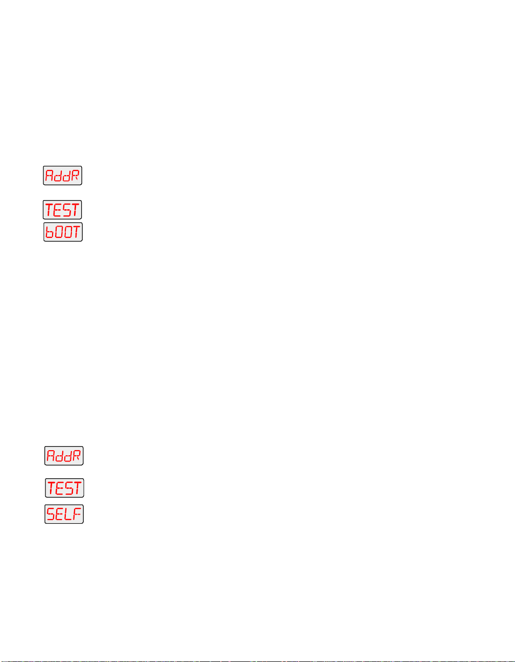
5. Press the <Enter> button to select the desired option.
Copying the Boot Code (BOOT)
When you upload new software to Technobeam-i fixtures, the new
software may contain a new boot code which must be copied to each
fixture. This is apparent if the LED displays a “BOOT DIFF” error.
not remove power from the fixture while performing a boot copy
can copy the new boot code using either the TEST menu or the SET
menu.
To accept and store the new boot code using the TEST menu:
1. Press and hold the <Menu> button until “ADDR” appears on the LED
display.
2. Using the <Up> and <Down> arrow buttons, scroll to the “TEST” menu
and press the <Enter> button to select the “TEST” menu.
3. Using the <Up> and <Down> arrow buttons, scroll to the “BOOT” option
and press the <Enter> button to select the “BOOT” option. The fixture
will store the new boot code, then automatically home.
Performing Self Tests (SELF)
This menu item performs the appropriate self tests for the following:
• ALL - performs all of the self tests listed below
• PAN - moves the pan motor from 0° to 180°
• TILT - moves the tilt motor from 0° to 95°
• COL - tests color wheel movement
• LTO - tests litho wheel movement
• FX - tests effects wheel movement
• FCUS - tests lens tube movement
• IRIS - tests iris movement
• SHUT - tests shutter strobe functions
• DIM - tests shutter dim flag movement
Do
. You
To perform a self test:
1. Press and hold the <Menu> button until “ADDR” appears on the LED
display.
2. Using the <Up> and <Down> arrow buttons, scroll to the “TEST” menu
and press the <Enter> button to select the “TEST” menu.
3. Using the <Up> and <Down> arrow buttons, scroll to the “SELF” menu
and press the <Enter> button to select the “SELF” menu.
4. Using the <Up> and <Down> arrow buttons, scroll to the desired option
(listed above). Press the <Enter> button to select the desired option.
The fixture will perform the selected self test.
5. Press the <Menu> button to exit the test.
Technobeam® User Manual Menu Options 3-21
Page 91
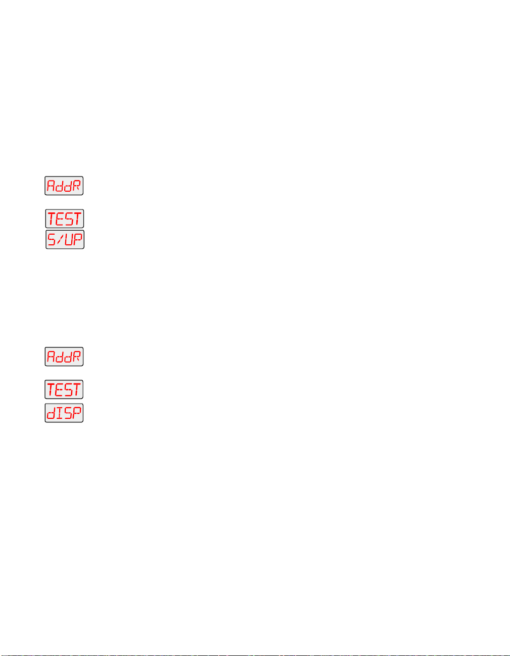
Note
The self tests will run continuously until you press the
<Menu> button to exit the test.
Placing the Fixture in Setup Mode (S/UP)
This menu item allows you to place the fixture in setup mode so that
you can mechanically home your fixture. If the fixture is out of home
(i.e., the iris or dim flags lose position), will emit an unusually loud
clicking noise when strobing or electronically homing. For more
information on how to mechanically home the fixture, contact High
End Systems customer service.
To place the fixture in setup mode:
1. Press and hold the <Menu> button until “ADDR” appears on the LED
display.
2. Using the <Up> and <Down> arrow buttons, scroll to the “TEST” menu
and press the <Enter> button to select the “TEST” menu.
3. Using the <Up> and <Down> arrow buttons, scroll to the “S/UP” option
and press the <Enter> button to select the “S/UP” option.
4. When the LED displays “SET NOW,” mechanically home the fixture.
5. After mechanically homing the fixture, press any button. This causes
the fixture to electronically home.
Testing the LE D Di spl ay (DISP)
To perform a self-test on the alphanumeric LED display:
1. Press and hold the <Menu> button until “ADDR” appears on the LED
display.
2. Using the <Up> and <Down> arrow buttons, scroll to the “TEST” menu
and press the <Enter> button to select the “TEST” menu.
3. Using the <Up> and <Down> arrow buttons, scroll to the “DISP” option
and press the <Enter> button to select the “DISP” option. The LED will
run through its self test.
4. Press the <Menu> button to exit the test.
Note
The self test will run continuously until you press the
<Menu> button to exit the test.
Infor matio n Menu (INFO)
The Information menu allows you to view current fixture information
such as internal temperature, lamp hours, total fixture hours, lamp
strikes, software version, DMX errors, sensor information, and DMX
data for any other device on the link. You can also reset the lamp
3-22 Menu Options Technobeam® User Manual
Page 92

hours or fixture hours. The procedures below are listed in the order
that they appear on the menu map.
Viewing the Logic Board Temperature (TEMP)
To view the current logic board temperatures:
1. Press and hold the <Menu> button until “ADDR” appears on the LED
display.
2. Using the <Up> and <Down> arrow buttons, scroll to the “INFO” menu
and press the <Enter> button to select the “INFO” menu.
3. Using the <Up> and <Down> arrow buttons, scroll to the “TEMP” option.
(This will be the first menu displayed.) Press the <Enter> button to
select the “TEMP” option.
4. The LED will display the temperature of the fixture’s logic board in
degrees centigrade.
The maximum temperature reading for the logic board is 76° C. If this
maximum temperature is exceeded, the fixture’s lamp, LAD, and
motors will shut down and the LED panel will display “OVER TEMP.”
Viewing the Current Lamp Hours (L/HR)
To view the number of hours the lamp has been on since this option
was reset:
1. Press and hold the <Menu> button until “ADDR” appears on the LED
display.
2. Using the <Up> and <Down> arrow buttons, scroll to the “INFO” menu
and press the <Enter> button to select the “INFO” menu.
3. Using the <Up> and <Down> arrow buttons, scroll to the “L/HR” option
and press the <Enter> button to select the “L/HR” option. The LED will
display the number of hours the lamp has been on since this option
was reset.
Viewing the Current Fixture Hours (F/HR)
To view the number of hours the fixture has been on since this option
was reset:
1. Press and hold the <Menu> button until “ADDR” appears on the LED
display.
2. Using the <Up> and <Down> arrow buttons, scroll to the “INFO” menu
and press the <Enter> button to select the “INFO” menu.
3. Using the <Up> and <Down> arrow buttons, scroll to the “F/HR” option
and press the <Enter> button to select the “F/HR” option. The LED will
display the number of hours the fixture has been on since this option
was reset.
Technobeam® User Manual Menu Options 3-23
Page 93

Viewing the Number of Current Lamp Strikes (L/ST)
To view the number of times the fixture has attempted to strike (turn
on) the current lamp:
1. Press and hold the <Menu> button until “ADDR” appears on the LED
display.
2. Using the <Up> and <Down> arrow buttons, scroll to the “INFO” menu
and press the <Enter> button to select the “INFO” menu.
3. Using the <Up> and <Down> arrow buttons, scroll to the “L/ST” option
and press the <Enter> button to select the “L/ST” option. The LED will
display the number of times the fixture has struck the current lamp.
Note
Lamp strikes are automatically reset when the lamp
hours are reset (see “Resetting Lamp Hours (L/RS)” on
page 3-27 below).
Viewing the Current Software Version (VER)
To view the current software version:
1. Press and hold the <Menu> button until “ADDR” appears on the LED
display.
2. Using the <Up> and <Down> arrow buttons, scroll to the “INFO” menu
and press the <Enter> button to select the “INFO” menu.
3. Using the <Up> and <Down> arrow buttons, scroll to the “VER” option
and press the <Enter> button to select the “VER” option. The LED will
display the fixture’s current software version.
Note
The software version is also displayed when you exit the
menu system and the normal alphanumeric display
cycles between displaying the software version, the
fixture name, and the fixture address.
Viewing DMX Status and Construct Values (FIXT)
This menu option allows you to view DMX status and construct values
for the fixture. You should follow this procedure if you are having a
particular problem with a fixture; for example, a color wheel that does
not respond to commands from the controller.
The following DMX status information is available for viewing:
• BRKS - number of DMX breaks (framing errors with zero data)
• FE - number of framing errors with a non-zero value (errors in data
transmission)
• OV - overruns (changing values could indicate data link/connector
problems)
•STRT - start code
3-24 Menu Options Technobeam® User Manual
Page 94
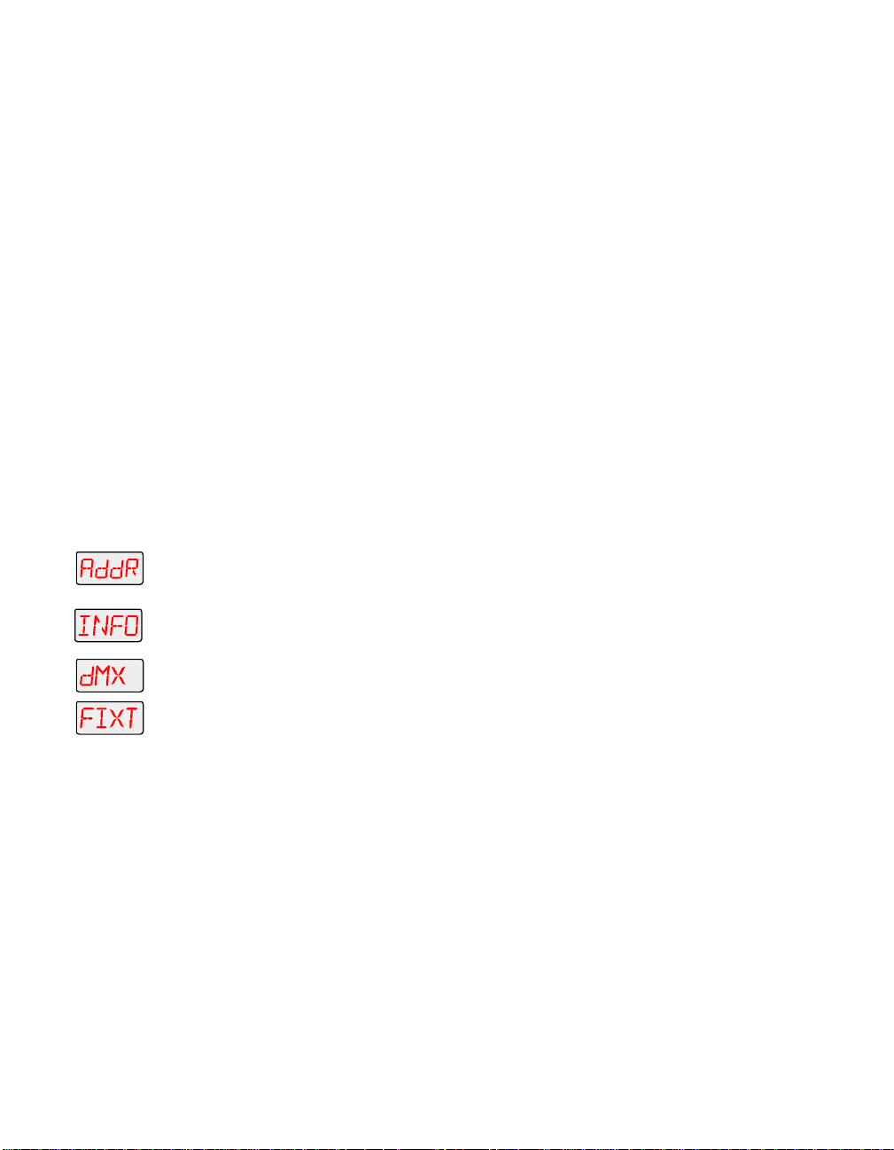
The following construct values are available for viewing:
• PANH - high 8-bit pan
• PANL - low 8-bit pan
• TLTH - high 8-bit tilt
•TLTL - low 8-bit pan
• COLC - color control channel
• COL - color wheel position
• LTOC - litho control channel
• LTO - litho wheel position
• LTR - litho rotation
• FCUS - lens tube position
• FX - effects wheel position
• FXR - effects wheel rotation
• IRIS - iris position*
• SHUT - shutter strobe
• DIM - shutter dim flag
• MSPD - MSpeed time
• LAD - Laser Aiming Device*
• CNTL - control channel
*
Note
To view the DMX status and construct values:
1. Press and hold the <Menu> button until “ADDR” appears on the LED
display.
2. Using the <Up> and <Down> arrow buttons, scroll to the “INFO” menu
and press the <Enter> button to select the “INFO” menu.
3. Using the <Up> and <Down> arrow buttons, scroll to the “DMX” menu
and press the <Enter> button to select the “DMX” menu.
4. Using the <Up> and <Down> arrow buttons, scroll to the “FIXT” menu
and press the <Enter> button to select the “FIXT” menu.
5. Using the <Up> and <Down> arrow buttons, scroll to the desired DMX
status or construct (listed above) and press the <Enter> button to
select the desired option. The LED will display the selected DMX status
or construct value.
If you are having a particular problem with the fixture, follow the steps
above to select a construct and view its value. After noting the value of
the construct you selected, use your controller to change that
construct’s value.
If the value changes on the fixture’s LED display, but the fixture still
does not respond, contact High End Systems customer service.
However, if the value does not change on the fixture’s LED display,
remove the fixture from the DMX link and try to change the construct’s
If your Technobeam-i does not have an iris and/or Laser
Aiming Device (LAD), the iris and LAD-related constructs
will have no functionality.
Technobeam® User Manual Menu Options 3-25
Page 95
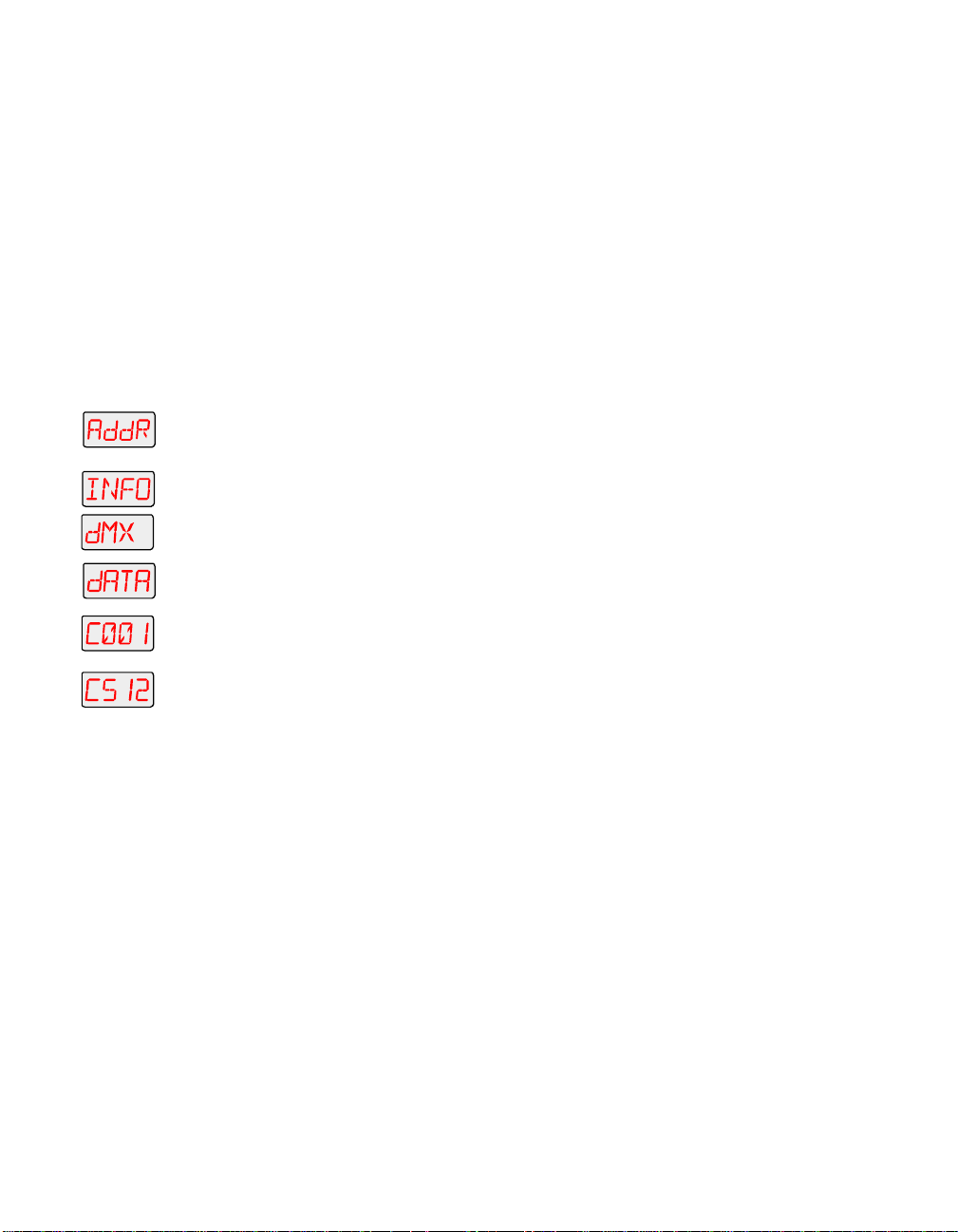
value using the fixture’s menu system. If the fixture then functions
normally, the problem was likely with the DMX link. Otherwise,
contact High End Systems customer service.
Viewing DMX Data for Another Dev ice (DATA)
This procedure allows you to use an Technobeam-i fixture to view DMX
channel values for other devices on the DMX link. You should use this
procedure either for testing devices that do not have built-in DMX
diagnostics, or for fixtures that are physically inconvenient to monitor
directly.
You can only view DMX channel values for devices which
have a channel range less than the viewing fixture’s
channel range.
to
Note
To view DMX data for another device on the DMX link:
1. Press and hold the <Menu> button until “ADDR” appears on the LED
display.
2. Using the <Up> and <Down> arrow buttons, scroll to the “INFO” menu
and press the <Enter> button to select the “INFO” menu.
3. Using the <Up> and <Down> arrow buttons, scroll to the “DMX” menu
and press the <Enter> button to select the “DMX” menu.
4. Using the <Up> and <Down> arrow buttons, scroll to the “DATA” menu
and press the <Enter> button to select the “DATA” menu.
5. Using the <Up> and <Down> arrow buttons, scroll to the desired DMX
channel (C001 - C512) and press the <Enter> button to select the
desired DMX channel. The LED will display the selected channel’s DMX
value.
If you are experiencing a particular problem with a device on the link,
follow the steps above to select a DMX channel in the device’s channel
range and view its DMX value. After noting the value of the channel
you selected, use your controller to change that channel’s value.
If the value of the DMX channel you selected does not change, there
may be a problem with the DMX cable or your transmitting device (i.e.
controller).
However, if the DMX channel value changes, but the device does not
respond, the device may be faulty. Consult the documentation
provided with that device for more information.
Viewing Sensor Information (SENS)
This menu option allows you to view whether a specified sensor if
working correctly. If you receive a “SENS ERR” error message on the
alphanumeric LED display, this information may help you determine
where the problem originates.
3-26 Menu Options Technobeam® User Manual
Page 96

The following sensor information is available:
• LTR - view whether the litho rotate (within the wheel) sensor is
obstructed (“OFF”) or is not obstructed (“ON”)
• LTO - view whether the litho wheel sensor is obstructed (“OFF”) or
is not obstructed (“ON”)
• COLR -view whether the color wheel sensor is obstructed (“OFF”) or
is not obstructed (“ON”)
• FX - view whether the effects wheel sensor is obstructed (“OFF”)
or is not obstructed (“ON”)
To view the specified sensor information:
1. Press and hold the <Menu> button until “ADDR” appears on the LED
display.
2. Using the <Up> and <Down> arrow buttons, scroll to the “INFO” menu
and press the <Enter> button to select the “INFO” menu.
3. Using the <Up> and <Down> arrow buttons, scroll to the “SENS” menu
and press the <Enter> button to select the “SENS” menu.
4. Using the <Up> and <Down> arrow buttons, scroll to the desired option
(listed above) and press the <Enter> button to select the desired option
to view its sensor information.
Resetting Fixture Hours (F/RS)
This menu item allows you to track the number of hours the fixture has
been operating.
To reset the fixture hours to zero:
1. Press and hold the <Menu> button until “ADDR” appears on the LED
display.
2. Using the <Up> and <Down> arrow buttons, scroll to the “INFO” menu
and press the <Enter> button to select the “INFO” menu.
3. Using the <Up> and <Down> arrow buttons, scroll to the “F/RS” option
and press the <Enter> button to select the “F/RS” option*. The LED will
display “0000” when the fixture hours are reset.
*
Note
This option has a 5-second delay to avoid inadvertent
changes. To reset the fixture hours, you must press and
hold the <Enter> button for at least 5 seconds.
Resetting Lamp Hours (L/RS)
This menu item allows you to track the number of hours the lamp has
been operating. You should reset the lamp hours every time you
change the lamp.
Technobeam® User Manual Menu Options 3-27
Page 97

To reset the current lamp hours to zero:
1. Press and hold the <Menu> button until “ADDR” appears on the LED
display.
2. Using the <Up> and <Down> arrow buttons, scroll to the “INFO” menu
and press the <Enter> button to select the “INFO” menu.
3. Using the <Up> and <Down> arrow buttons, scroll to the “L/RS” option
and press the <Enter> button to select the “L/RS” option*. The LED will
display “0000” when the lamp hours are reset.
*Note
This option has a 5-second delay to avoid inadvertent
changes. To reset the lamp hours, you must press and
hold the <Enter> button for at least 5 seconds.
Preset Menu (PRST)
The Preset menu allows you to turn preset playback off or on, view
which scene is currently playing, and create/edit a scene using the onboard memory to program the fixture for stand-alone operation. This
menu also allows you to copy a scene within the fixture’s on-board
memory, capture a scene from your DMX controller to the fixture’s onboard memory, and enable the fixture’s factory-programmed preset
sequence (self demo).
Setting Preset Playback (PL AY)
This menu option allows you to turn preset playback on or off and
view which scene is currently playing in preset playback mode.
To set preset playback on or off, or to view the current scene:
1. Press and hold the <Menu> button until “ADDR” appears on the LED
display.
2. Using the <Up> and <Down> arrow buttons, scroll to the “PRST” menu.
Press the <Enter> button to select the “PRST” menu.
3. Using the <Up> and <Down> arrow buttons, scroll to the “PLAY” menu.
(This will be the first option displayed). Press the <Enter> button to
select the “PLAY” menu.
4. Using the <Up> and <Down> arrow buttons, scroll to the “ON” option to
set preset playback on, the “OFF” option to set preset playback off, or
the “SCN” option to display which scene is currently playing. Press the
<Enter> button to select the desired option.
Note
Scene 1
back scenes.
be programmed before the fixture can play
must
3-28 Menu Options Technobeam® User Manual
Page 98

Editing or Creating an On-Board Memory Scene (ED IT)
This menu item allows you to edit or create a scene using the fixture’s
on-board scene memory. Using this menu option, you can change the
value of any construct in any of the on-board scenes. For detailed
information on editing or creating a scene, see Chapter 4.
To edit/create a scene:
1. Press and hold the <Menu> button until “ADDR” appears on the LED
display.
2. Using the <Up> and <Down> arrow buttons, scroll to the “PRST” menu
and press the <Enter> button to select the “PRST” menu.
3. Using the <Up> and <Down> arrow buttons, scroll to the “EDIT” menu
and press the <Enter> button to select the “EDIT” menu.
to
4. Using the <Up> and <Down> arrow buttons, scroll to the scene (“SN01”
to “SN16”) that you want to edit or create and press the <Enter> button
to select the desired scene.
Copying an On-Board Memor y Scene (COPY)
1. Press and hold the <Menu> button until “ADDR” appears on the LED
display.
2. Using the <Up> and <Down> arrow buttons, scroll to the “PRST” menu
and press the <Enter> button to select the “PRST” menu.
3. Using the <Up> and <Down> arrow buttons, scroll to the “COPY” menu
and press the <Enter> button to select the “COPY” menu.
4. The LED will display “FROM.” Press the <Enter> button to enter the
“FROM” menu.
5. Using the <Up> and <Down> arrow buttons, scroll to the scene that you
to
to
want to copy from (source scene) for either user A (“FA01” - “FA16”) or
user B (“FB01” - “FB16”). Press the <Enter> button to select the desired
scene.
6. The LED will display “TO.” Press the <Enter> button to enter the “TO”
menu.
7. Using the <Up> and <Down> arrow buttons, scroll to the scene that you
want to copy to (destination scene) for either user A (“TA01” - “TA16”)
or user B (“TB01” - “TB16”). Press the <Enter> button to select the
desired scene.
The fixture will copy the desired scene to the selected scene location.
When the fixture finishes the copy successfully, “DONE” will appear
briefly in the fixture’s LED display.
Capturing a Preset Scene (CAPT)
Preset capturing is a way to automate the creation of scenes on
multiple Technobeam-i fixtures connected to a DMX 512 link. Use a
Technobeam® User Manual Menu Options 3-29
Page 99

to
DMX controller to create a scene, then save (capture) the scene into a
fixture’s presets to play back the scene without the controller.
After creating a scene with your DMX controller, follow the instructions
below for each fixture on which you want to capture preset scenes:
1. Press and hold the <Menu> button until “ADDR” appears on the LED
display.
2. Using the <Up> and <Down> arrow buttons, scroll to the “PRST” menu
and press the <Enter> button to select the “PRST” menu.
3. Using the <Up> and <Down> arrow buttons, scroll to the “CAPT” menu
and press the <Enter> button to select the “CAPT” menu.
4. Using the <Up> and <Down> arrow buttons, scroll to the scene you
want to copy the preset scene to (destination scene) and press the
<Enter> button.
Pressing the <Enter> button will copy the DMX-512 controller’s preset
scene to the selected scene on your fixture’s on-board 16 scene
memory. When the fixture finishes the capture successfully, “DONE”
will appear briefly in the fixture’s LED display.
Note
You must use the fixture’s on-board scene memory to
manually
constructs, since a DMX controller will not transmit
those construct values. For more information on using
the fixture’s on-board scene memory, refer to the
Technobeam
select values for the XFAD, DLAY, and TIME
®
User Manual
.
Enabling the Preset Default (DFLT)
This menu item enables the factory-programmed 16 preset sequence
or fixture self demo. Enabling this menu item will
programmed scenes
memory for either user A or user B.
To enable the self-demo:
1. Press and hold the <Menu> button until “ADDR” appears on the LED
display.
2. Using the <Up> and <Down> arrow buttons, scroll to the “PRST” menu
and press the <Enter> button to select the “PRST” menu.
3. Using the <Up> and <Down> arrow buttons, scroll to the “DFLT” menu
and press the <Enter> button to select the “DFLT” menu. The LED
display will show “OK?”
4. Press the <Enter> button to enable the self-demo or press <Menu> to
exit the menu option.
Note
or construct values on your fixture’s on-board
To play the fixture’s self-demo, you must set preset
playback on (see “Setting Preset Playback (PLAY)” on page
3-28).
3-30 Menu Options Technobeam® User Manual
erase any pre-
Page 100

Chapter 4 Preset Programming
Programming Overview ...................................................................................4-2
What is a “Scene”? ...............................................................................4-2
Stand-alone Operation vs. a Controller ..............................................4-2
Macros ................................................................................................4-2
Preset Playback Options .....................................................................4-3
General Information ...........................................................................4-3
Subject to Change ..................................................................4-3
Enter and Menu Keys .............................................................4-3
MSpeed vs. Fast Changes .......................................................4-3
Selecting Constructs and Values ...........................................4-4
Creating a Scene ..............................................................................................4-4
Orienting and Powering On the Fixture ..............................................4-4
Turning on the Lamp ..........................................................................4-4
Opening the Shutter ...........................................................................4-5
Positioning the Mirror ........................................................................4-6
Focusing on a Litho ............................................................................4-6
Selecting Color Wheel Constructs ......................................................4-6
Selecting a Color Wheel Pause Time ...................................................4-7
Selecting Effects Constructs ...............................................................4-7
Refocusing the Fixture .......................................................................4-7
Setting a Delay Time ..........................................................................4-7
Creating Scene 2 .................................................................................4-8
Playing Back Both Scenes ...................................................................4-8
Synchronizing Preset Playback .......................................................................4-9
Setting Up the Fixtures .......................................................................4-9
Adding Fixtures ............................................................................... 4-11
Capturing Presets ......................................................................................... 4-11
Technobeam® User Manual 4-1
 Loading...