

Page 1

Automated Luminaire
User Manual
Version 1.1 — Revision B
Page 2

To view a list of ETC trademarks and patents, go to etcco n n ect .co m/ip. All othe r trademarks,
both marked and not marked, are the property of the ir respective owne rs.
Information and specifications in this document are subject to change without notice. High End
Systems assumes no responsibility or liability for any errors or inaccuracies that may appea r in
this manual.
Page 3

Table of Contents
Introduction
Contacting High End Systems
Headquarters
Technical Support
Patents
Terms and Conditions and Warranty Information
Product Modification Warning
Mise En Garde Contre La Modification Du Produit
Produktmodifikationswarnung
Av vertenza S ul la Modifica Del Prodotto
Advertencia De Modifi catión Del Producto
Important Safety Information
Fixture Overview
Dimensions
1
1
1
1
1
1
1
2
2
2
2
3
4
5
Safety Considerations
General Operation and Use Guidelines
Install the Fixture
Power
DMX Control
DMX Connector Pinout
Considerations for Ethernet (Art-Net) Connectors
Connect DMXCables to Fixture
Terminate DMX
Set the DMX Start Address
6
7
8
10
11
11
11
12
13
13
Table of Cont ents i
Page 4

DMX Channels
13
Configure the Fixture
Navigate the User Interface
Set Fixture Parameters
DM X Address
Info Menu
Set Menu
Test Menu
Preset Menu
Error Codes
Cleaning and Maintenance
14
14
15
15
15
17
20
21
23
26
ii SolaSpot 3000
Page 5

Introduction
Congratulations on your purcha se of the SolaSpot 3000 automated framing fixture. This manual
provides important information for the sa fe installation, configuration, and maintenance of your
SolaSpot 3000 fixture.
Contacting High End Systems
High End Systems, Inc. is an ETC company.
Headquarters
For Custome r Service or Sales support, please contact our company headquarte rs:
2105 Gracy Farms Lane
Austin, TX 78758 USA
Te l: 512.836.2242
Fax: 512.837.5290
Toll-free: 800.890.8989
Website: high end.com
Technical Support
If you are having difficulties installing, configuring, or operating your SolaSpot 3000, your most
convenient resources are the references given in this manual. To search more widely, try the
High End Systems, Inc. we bsite a t hig h end.com.
24-hour emergency support is a vailable. Contact High End Technical Services at
+1 (512) 836-2242.
Patents
NO T ICE OF INT E LLE CTUAL PROPERTY R IGHT S
High End Systems, Inc. products are protected by one or more patents listed on the High End
Systems, Inc. website: h ttps://www.hig h end.com/patents and/ or are subject to one or more
pending patents.
Terms and Conditions and Warranty Information
Complete te rms and conditions and warranty information can be found on the High End
Systems, Inc. website:h ttps://www.hig h end.com/pub /products/HES-W arran t y-
Information.pd f .
Product Modification Warning
High End Systems products are designed and manufactured to me et the requirements of the
United States and International safety regulations. Modifications to the product could affect
safety and render the product non-compliant to relevant safe ty standards.
Int roduct ion 1
Page 6

Mise En Garde Contre La Modification Du Produit
Les produits High End Systems sont conçus et fabriqués conformément aux exigences de
règlements internationaux de sécurité. Toute modication du produit peut entraîner sa non
conformité aux normes de sécurité en vigueur.
Produktmodifikationswarnung
Design und Hestellung von High End Systems e ntprechen den Anforderungen der U.S.
Amerika nische n und interna tionalen Sicherheithsvorschriften. Abände runge n dieses Produktes
können dessen Sicherheit beeinträchtigen und unter Umständen gegen die diesbezügliche n
Siche rheitsnormen verstoße n.
Avvertenza Sulla Modifica Del Prodotto
I prodotti di High End Syste ms sono stati progetta ti e fabbricati per soddisfare i requisiti delle
normative di sicurezza statunitensi ed inte rnazionali. Qualsiasi modifica al prodotto potrebbe
pregiudicare la sicurezza e rendere il prodotto non conforme agli standard di sicurezza
pertinenti.
Advertencia De Modificatión Del Producto
Los productos de High End Systems están diseñados y fabricados para cumplir los re quisitos de
las reglamentaciones de seguridad de los Estados Unidos e inte rnacionales. Las modificaciones
al producto podría n afectar la segurida d y de jar al producto fuera de conformidad con las
normas de seguridad relevantes.
2 SolaSpot 3000
Page 7
Important Safety Information
Please read all instructions prior to assembling, mounting, and operating this equipme nt.
Continued and safe operation of this fixture is the responsibility of the operator. This ma nual will
give tips for that continued safe operation. At any time plea se contact High End Systems
technical support for any safety concerns.
The following international note, ca ution, and warning symbols appear in margins throughout
this manual to highlight important messages.
Note: Notes are helpful hints and information that is supplemental to the main text.
CAUTION: T his statement ind icates that wh ile operating , equipme nt su r faces
may reach ve ry h igh t emp eratu r es. Allo w t h e fixture to coo l befo r e handlin g o r
servicing .
CAUTION: A Cau t ion sta tement indicat es situat ions where t h ere may be
undefine d o r unwanted consequen ces o f an act ion, potent ial for data loss or an
eq u ipment p r oble m.
WA RNING: A W arning st atemen t indica tes sit u atio ns wh ere d amage may
occur, people may be h armed, o r there are serio u s o r dange rous co n se quences of
an a ction
WA RNING: RIS K OF ELE CTR IC SHOCK! This warning statemen t ind icates
sit u atio ns wh ere there is a risk o f elect r ic shock.
Int roduct ion 3
Page 8
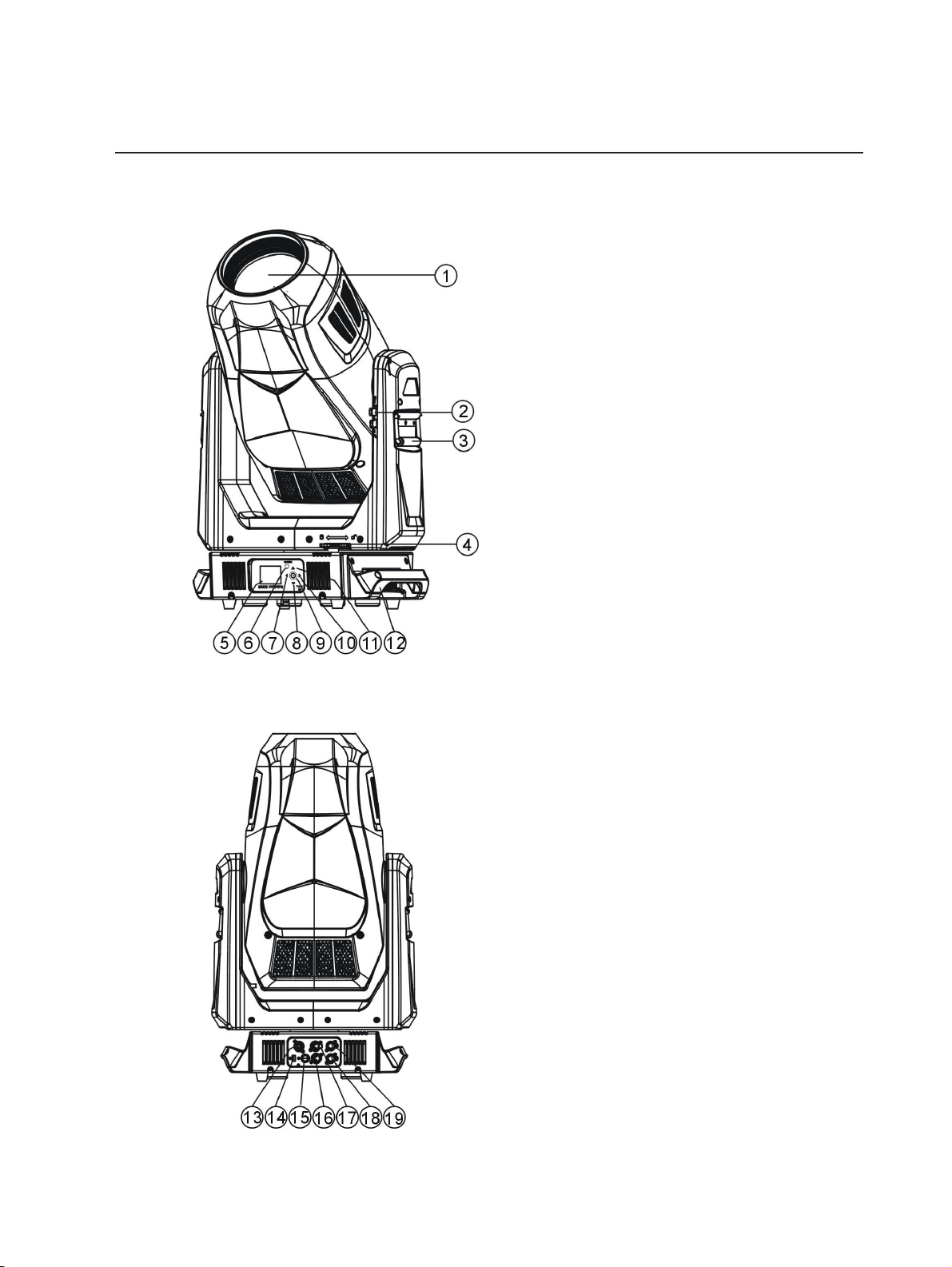
Fixture Overview
For technica l specifications of the SolaSpot 3000 fixture, see the technical data sheet:
https://www.highend.com/documentation/SolaSpot3000/SolaSpot-3000-Datasheet.pdf
1: Lens
2: Tilt lock
3: Retractable yoke handle
4:Pan lock
5: Display
6: [MODE/ESC] button
7: Left button
8: Down button
9: [Enter] button
10: Right button
11: Up button
12: Handle
13: Power in
14: USB
15: Fuse
16: DMXout
17: DMX in
18: Art-Net out
19: Art-Net in
4 SolaSpot 3000
Page 9
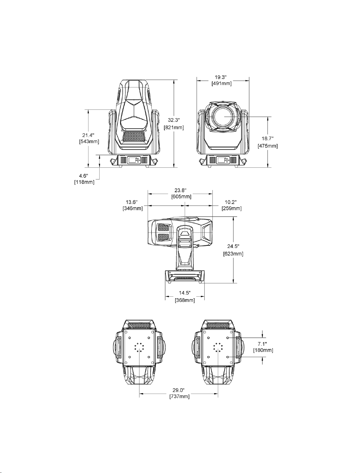
Dimensions
Dimensions shown are listed as inches [millimeters].
Fix ture Over view 5
Page 10
Safety Considerations
•
•
•
•
•
•
•
•
•
•
•
•
•
•
•
In order to ensure safe operation, follow the safety instructions and warning notes in this user
manual and any instructions from the manufa cturer re presentative.
The SolaSpot 3000 fixture is intended for professional use only. Not for residential use .
Read the entire manual before using this equipment.
Conta ct your High End Systems dealer or High End Systems technical support before
performing any service in order to maintain warranty coverage .
WA RNING: For your saf ety, read t he follo wing warn ings an d n otices bef ore
use:
Th is equ ipment is designed f o r opera tio n b y qualifie d personnel only.
Disco n n ect t he unit from power and DMX befor e servicing.
Rep lace f u ses with t h e specified t ype and r atin g o nly.
Make su r e that t h e availab le voltage is within t h e stated r ange.
NEMA Typ e 1 Enclo sur e, indoor use, dry locations only. Do n ot use
outd o o rs. This fixture is intend ed for u se wh ere h umidity d oes not exceed
90% (non-co ndensing).
Do n ot use this f ixture with a damaged p ower lead (cor d set). If t h e lead is
damag ed, it must be r eplaced by a qualif ied t ech n ician with a n equivalen t
type bef o re use. Cont act your local author ized dea ler f or sp are p ower leads.
Do n ot use this f ixture if t h e lens, prote ction scre en, or ult r aviolet scr een is
damag ed. Damage d len ses mu st b e replaced bef o re use. Cont act your local
au t h orized d ealer for a replacement.
When the f ixture h as been sto r ed or t r ansported in cold temperat ures, allow
it to warm to r o o m t emperat ure f o r a minimu m o f o n e hour b efore applying
power . Ap p lying p ower to a cold fixture may cause damag e to the f ixture
an d void the man u fact urer warrant y.
Th is is a Class I d evice and must b e groun d ed.
Do n ot project t he beam o nto co mbu stible su bst ances.
Keep f ixture h ead at le ast 0.1 m (0 .33 ft) away from an y flamma ble
mater ials.
Minimu m d istance to lig hted o b jects:2 m (6.5 6 f t).
When you p o wer on the fixture, you may notice smoke or odor. This is
normal and sho u ld d ecr ease grad ually. If smoke or odor p ersists, d iscon n ect
the fixture f rom power and co n tact your Hig h End Syst ems d ealer o r High
En d Systems technica l suppo r t.
WA RNING: RIS K OF ELE CTR IC SHOCK! Do n o t opera te this device wit h t he
co ver o pen.
CAUTION: Hot Surf aces. Allo w t he fixture t o cool co mpletely before h andling
an d ser vicing.
6 SolaSpot 3000
Page 11

CAUTION: Damages caused b y the disreg ard of this u se r man ual are not
•
•
•
•
•
•
•
•
•
•
•
•
subject to warran t y. The a uthorized d ealer will n ot accep t liabilit y for any
resultin g d efects or problems.
General Operation and Use Guidelines
This fixture is only allowed to be operated with the maximum alternating current that is
stated in the te chnical specifications labe l provided on the fixture.
Lighting effects are not designed for permanent operation. Consistent operation breaks
may ensure that the fixture will serve you for a long time without defects.
Do not shake the fixture. Avoid brute force when installing or operating the fixture.
When choosing the installation location, make sure that the fixture is not exposed to
extreme heat, moisture or dust.
If using the supplied Ome ga brackets with quick-locking thumb scre ws for fixture hanging,
ensure that the thumb screws have engaged a comple te 90-degree positive latch.
Operate the fixture only after ha ving familia rized yourself with its functions. Do not permit
other persons who are not qualified and familiar with its functions to operate the fixture.
Most damages are the result of unprofessional operation.
Please use the original packaging if the fixture is to be transported. ETC and High End
Systems, Inc. will not be responsible for the fixture if pack aging other than manufacturer
provided packa ging is used.
Do not modify the fixture. Any modifications will void the manufacturer warra nty.
This manual describes the proper installation and operation of this fixture. Using this
fixture in any way other than the intende d use may cause damage and may void the
factory warranty.
Misuse of this fixture or using it in a way different from the methods described in this
manual may lead to personal injury a nd/or equipment failure.
The light source of this fixture is not replaceable. When the light source re aches its end of
life, replace the fixture.
If you do not provide power to the fixture, the battery on the SolaSpot 3000 may drain
fully after 7–10 days. After you provide power to the fixture, the ba ttery will recharge
within 3–4 hours.
Safety Considerations 7
Page 12

Install the Fixture
•
•
•
•
•
•
•
•
•
•
•
WA RNING:
Th e installation location must su p p ort a minimum point lo ad of 10 t imes the
weight of t h e fixtur e.
Th e installation mu st alwa ys be se cur ed with a se cond ary sa fety att ach men t .
An approp r iat e safety ca ble is supplied .
Sa fety cable attachment must b e rated b y a sa fety factor o f 1 0.
Use of third part y clamps ar e permit ted, but they sh ould comply wit h t h e
local ju risdiction a nd be a pproved by the Author ity Ha ving Jurisd ictio n .
A su p portive and stab le su r face mu st b e used when t he fixtur es are placed
on t h e fee t.
Th e opera tin g t emp erat u re ran g e for t h is fixtu r e is - 1 0 °C–4 5 °C (14°F–
113°F). Do n o t operate the fixture outside of this r ange.
Neve r st and directly below the installed fixtur e wh en mounting, r emo ving,
or ser vicing.
All safet y and t ech nical aspects of fixtu r e in sta llation sh all be approved b y a
qualifie d person b efore o perat ion .
Th e installation mu st b e reg u lar ly in spected b y a q ualified p erson.
Overhead riggin g must b e perfo r med by q u alified p ersonnel.
Please con sider GB7000.1-2015, GB700 0 .217-2 0 0 8, an d o t her n atio nal
norms during the installation.
CAUTION: Follow all local co d es and r ecommended p r act ices by t he Au t h orit y
Having Jurisd iction . The installa tion must only be carr ied ou t b y a q u alified
per son .
You can install the fixture in any of the orientations shown below.
8 SolaSpot 3000
Page 13
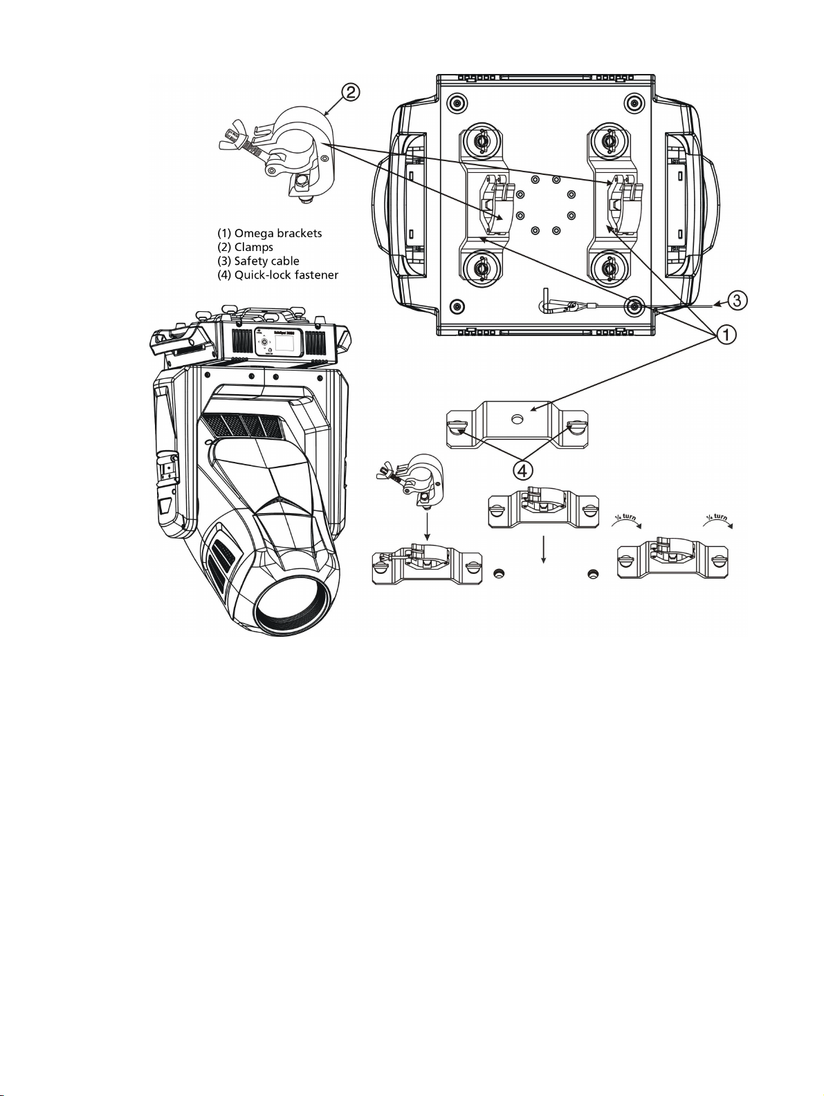
1. Assemble the third-party clamp or Omega clamp to the O mega bracket and secure
together using appropriately sized hardware (not provided).
2. Align the assembled Omega bracket and quick-lock fasteners into the respective holes on
the bottom of the fixture upper enclosure.
3. Tighten each of the quick-lock fasteners fully, turning clockwise. You will hear and feel a
click when the fastener is fully secured.
4. Repeat steps 1 through 3 for the second clamp and bracket.
5. Attach the provided safety cable through the attachment point on the bottom of the
fixture upper enclosure and secure to the trussing system or other safe installation point.
Follow local codes and recomme nded safety standards for securing the fixture to the
installation location.
6. Attach the fixture to the installation location using the installed clamps, using the clamp
manufacturer's instructions for a secure fit. When using the Omega clamp, close the
safety and fully tighten the clamp wing nut until secure.
7. Inspect the installation prior to lifting the fixture overhe ad.
Inst all the Fixture 9
Page 14

Power
VAC Amps Hz Watts VA PF Cr est Factor
100 14.7 50 1471 1461 0.99 1.40
120 11.8 60 1420 1416 0.99 1.41
200 6.6 50 1323 1322 0.99 1.49
208 6.3 60 1322 1326 0.99 1.47
220 6.0 50 1321 1346 0.99 1.51
240 5.5 60 1316 1324 0.98 1.50
CAUTION: Using t h is fixtu r e below 100V on a 1 5 A breaker may cau se t h e
breaker t o t r ip. Ensure t hat the circuit can handle the f ixture's maximum potential
draw before you connect it .
10 SolaSpot 3000
Page 15

DMX Control
The SolaSpot 3000 fixture operates on standard DMX512 control bus, controlled by a DMX
console. A SolaSpot 3000 fixture requires 47 channels of DMX512.
Attach the fixture to the control bus using a two-core, shielde d cable with a 5-pin XLR connector
(Be lden 9729 is preferred).
Two XLR termination receptacles are available: one for connection of DMXInput, and one for
DMXOut (used when daisy-cha ining to additional fixtures on the DMX control bus).
DMX Connector Pinout
For DMXInput, the DMX cable must have a ma le XLR conne ctor on one end of the cable. When
daisy-chaining DMX, the other end of the cable must have a female XLR connector. Terminate
the cable ends as indicated in the pinout image below.
Considerations for Ethernet (Art-Net) Connectors
For fixtures connected via Ethernet (Art-Net), cable distance should not excee d 100m, and no
more than 20 fixtures should be connected in a da isy chain.
DMX Cont rol 11
Page 16
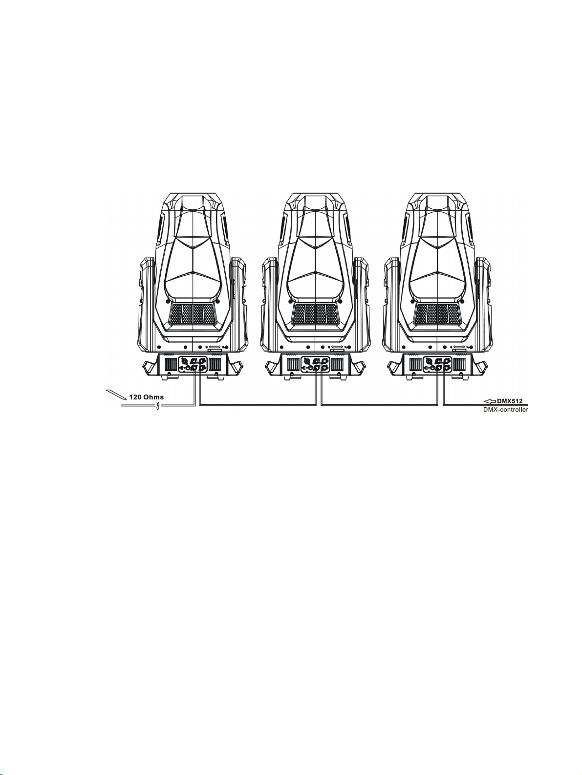
Connect DMXCables to Fixture
The following instructions are guidelines for connecting DMX to your fixture. Your installation
may vary.
1. Conne ct the male XLR connector of a DMX data cable to the DMX Out connector on the
DMX control source.
2. Conne ct the female XLR connector of the DMX data cable to the DMX In connector of the
first fixture on the DMX control run.
3. Continue linking the remaining fixtures connecting a cable from the DMXOut connector
of each fixture to the DMXIn connector of the next fixture on the control run.
12 SolaSpot 3000
Page 17

Terminate DMX
For installations with a long DMX control run or an electrically noisy environment, we
recommend tha t you use a DMX terminator or install a resistor on the last fixture of the
DMXcontrol run to prevent corruption (data reflection) of the digital control signal by electrical
noise.
A DMXterminator is an XLR plug with a 120 Ω resistor connected between pins 2 and 3, which
can be installed into the DMX output receptacle of the last fixture in the DMX control run. This
plug is available and sold separately. Contact your loca l High End dealer for ordering
information (visit https://www.highend.com/a bout/conta ct-u s to locate a High End dealer).
Alternatively, terminate the link by installing a 120 Ω , 1/4 watt (minimum) re sistor in the
fixture’s DMX Out (female) cable connector in the la st fixture on each DMX control run.
1. Disassemble a male XLR connector.
2. Solder a 120 Ω resistor, minimum 1/4 watt, between pin 2 and pin 3.
3. Reassemble the XLR connector.
5-pin terminator
Set the DMX Start Address
Give each fixture a unique DMX starting addre ss when using a DMX control signal so that the
correct fixture responds to the control signals. This DMX start address is the channel number
from which the fixture starts to “listen” to the digital control information sent out from the DMX
control source.
Modify the fixture DMX start address on the user interface, located on the upper enclosure. See
DMX Ad d r ess o n p age1 5
Exa mple : The SolaSpot 3000 has 47 channels. If you set the DMXstarting address of
the first fixture to 1, you could se t the second fixture to 48 (47+1), the third to 95
(48+47), and so on.
.
DMX Channels
The most current DMXControl Protocol data for the SolaSpot 3000 can be found on the High
End Systems, Inc. website:
https://www.highend.com/documentation/SolaSpot3000/SolaSpot3000-protocol.pdf
DMX Cont rol 13
Page 18
Configure the Fixture
Mode
Esc.
Mode
Esc.
Mode
Esc.
You can configure SolaSpot 3000 fixtures through the onboard user inte rface.
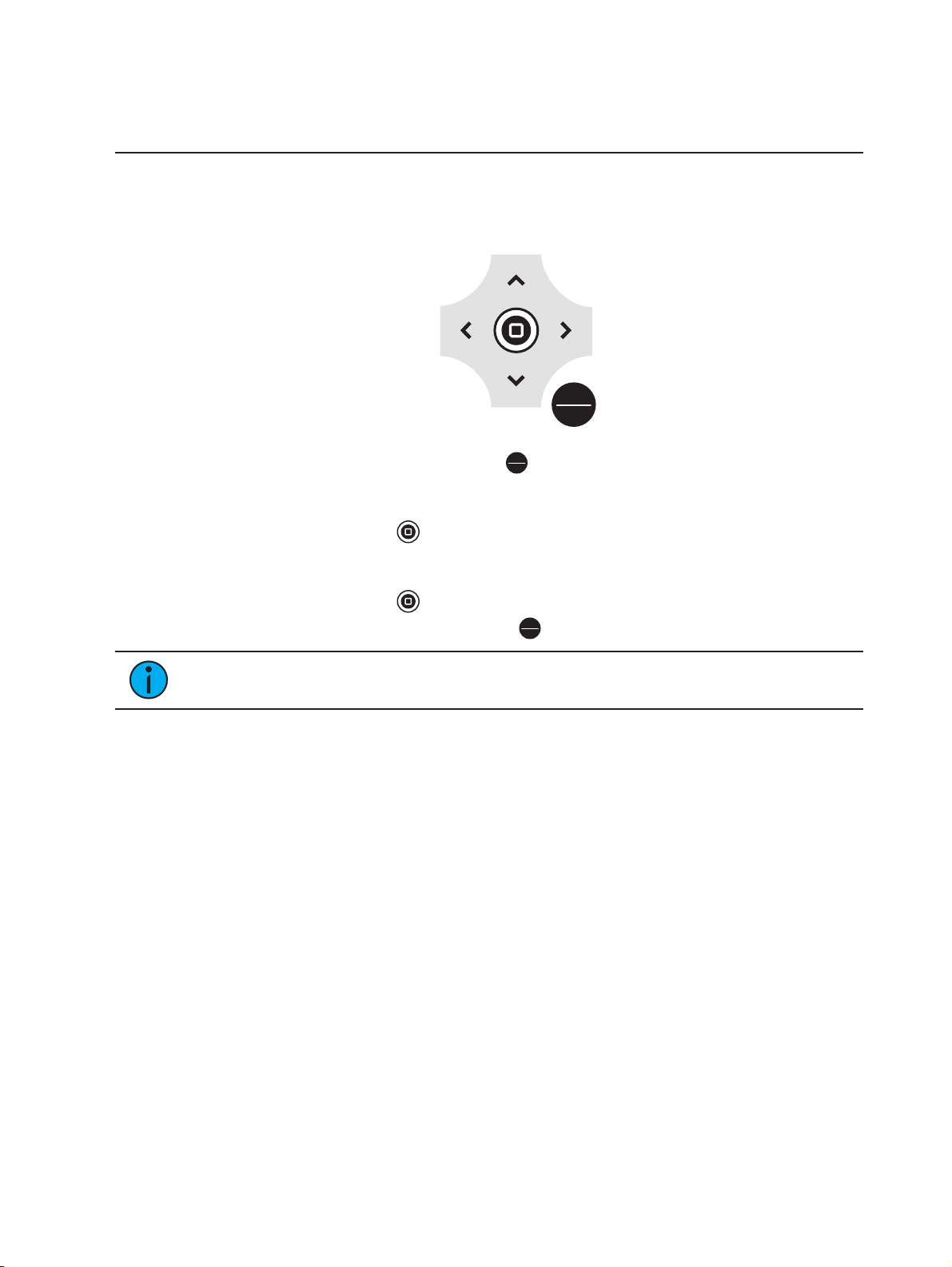
Navigate the User Interface
1.
Press and hold the [MODE/ESC] button (
powered by battery when the fixture has no power.)
2. Browse the menu by pre ssing the up, down, left, or right navigation buttons.
3.
Press the [Enter] button ( ) to se lect a me nu item.
4. Modify the selection by pressing the up, down, left, or right navigation buttons according
to the selection.
)until the display flashes. (The display is
5.
Press the [Enter] button ( ) to confirm a modified selection.
6.
To exit the menu, press the [MODE/ESC] (
)button.
Note: If you press the [Enter] button to confirm a selection and push no other
buttons, the user interface returns to the default display after 10 seconds.
14 SolaSpot 3000
Page 19

Set Fixture Parameters
•ON•
•ON•
This section provides instructions to configure and set up the Sola Spot 3000. See
User Inter face on the p r evious pag e
Provide power to the fixture before configuring it. If you do not provide power, the fixture will
use battery power to power the user interface.
for information on the navigation buttons.
Navigate t he
DMX Address
Na vigat e : Main Menu → Address
Se t the DMX address for the fixture. The default value is 001.
Info Menu
Set the Time Informa tion
Na vigat e : Main Menu → Info → Time Info
Pa rameter Value Descriptio n
Running time of the fixture from the last time that
Curre nt Time XXXX (Hours)
Ttl Life Hrs XXXX (Hours) Total running time of the device, shown in hours (h).
Last Run Hrs XXXX (Hours)
the fixture was powered on, shown in hours (h). The
counter resets after the fixture is turned off.
Running time of the fixture from the last time that
the fixture was powered on, shown in hours (h).
LEDHours XXXX(Hours)
TimerPIN Pa ssword = XXX
Clr Last Run
LEDTime PIN Password = XXX
Clear LE D T ime
OFF
OFF
Total running time of the fixture LEDs, shown in
hours (h).
Enter the Time r PIN. The default Timer PINis 038.
You must enter the Timer PIN in order to access the
Clr Last Run parameter.
You must enter the Timer PIN to access this para meter. Select ON to clear the va lue for the Current
Time parameter for the fixture.
Enter the LED Time PIN. The default LED Time PINis
038. You must enter the LEDTime PIN in order to
access the Clear LEDTime parameter.
Please contact technical support at High End
Systems, Inc. before using this parame ter to clear
the LEDHours value. Se e
Systems o n p age1
You must enter the LEDTime Pin to access this
parameter.
Se lect ONto clear the value for the LED Hours
parameter.
Co ntacting Hig h End
.
Configur e the Fixt ur e 15
Page 20

View Fixture E rrors
Na vigat e : Main Menu → Info → Error Info
Displa ys any curre nt fixture errors.
View DMX Values for Channels
Na vigat e : Main Menu → Info → DMX Value
View the DMX value of each of the fixture's channels (parameters of the fixture). Scroll to the
parameter that you want to view (Pan, Tilt, etc. ) and vie w the va lue.
View Fixture H ead T emperature
Na vigat e : Main Menu → Info → Head Temp.
Displa ys the current fixture tempe rature as read from the fixture head (near the CMYfilter).
View P ower T e mperature
Na vigat e : Main Menu → Info → Power Temp.
Displa ys the current temperature as read from the power supply in the fixture base, which can
help you to determine if the power supply is overheating.
View Fan S pee ds
Na vigat e : Main Menu → Info → Fan Speed
Displa ys the speeds of the fixtures fans (in RPM).
View S e nsor Status
Na vigat e : Main Menu → Info → LED Sensor.
Displa ys the status of the se nsors, which can help you to determine whether the fixture is
recognizing the movement and position of the whe el. The display toggles be tween ON and OFF
as the magnet passe s the sensor.
View E therne t IP Addre ss
Na vigat e : Main Menu → Info → Ethernet IP
Displa ys the Ethernet IP address for the fixture. You can modify this value in the Set menu. See
Access Service Set ting s o n p age18
.
View S oftware Version
Na vigat e : Main Menu → Info → Software Ver
Displa ys the software version for the fixture.
16 SolaSpot 3000
Page 21
Set Menu
•
•
•
•ON•
•ON•
•
•
•ON•
•
•
•
•
•
•
•
•
•
•
•ON•
Set the Sta tus Options
Na vigat e : Main Menu → Set → Status
Pa rameter Value Descriptio n
No DMX Mode
Pa n Reverse
Tilt Reve rse
Pa n Degree
Encoders
Pa n/Tilt Spd 1–4
Close
Hold
Auto
OFF
OFF
630
540
OFF
Control mode when DMXis absent. The de fault
value is Hold.
Reverse the pa n movement of the fixture. The
default value is OFF.
Reverse the tilt movement of the fixture. The default
value is OFF.
Change the pan rotation of the fixture from the
default setting of 540 degrees to 630 degrees.
Turn on or off the encode r feedback for pan and tilt
movement. You may want to turn off encoders when
working on a fixture so that you can move pan and
tilt without the fixture automatically moving back to
position.
Se t the speed (scan mode) of pan and tilt movement. The default value is 1. Use this parameter to
make fine adjustments to pan and tilt movement in
order to correct for mis-stepping when the fixture is
installed on its side (side-hung, or "Outrig").
Hibernation mode forces the LEDs and stepper
Hibernation
OFF
1–99 minute s
motors to power off when the fixture loses DMX control signal for a set period of time. The de fault time
setting is 15 minutes.
Se t when the Defogger (heater for the front lens)is
turned on:
Defogger
Defog OnOP
Defog OnPwr
Defog Off
Defog OnOP :Turn on Defogger when LEDs are
above 0% inte nsity
Defog OnPwr: Turn on Defogger when the fixture
is powered (default value)
Defog Off:Turn off Defogge r
Dimming Mode
Standard
Theatrical
Se t the dimming curve. The default value is Standard.
Turn on when the fixture is installed on its side (side
Out Rig Mode
OFF
hung, or "Outrig"). T his parameter reduces the
speed of pan and tilt movement to correct for misstepping.
Configur e the Fixt ur e 17
Page 22

Sele ct Input
•
•
•
•
•ON•
•
•
•
•
Na vigat e : Main Menu → Set → Select Input
Se lect the control input for the fixture:
DMX Only
Art-Net on IP2
Art-Net on IP10
sACN
Set Unive rse for Art-Net
Na vigat e : Main Menu → Set → Set Universe
When using Art-Net control input, se t the universe (000–255).
Acce ss S e rv ice S e ttings
Na vigat e : Main Menu → Set → Service Setting
Pa rameter Value Descriptio n
Enter the Service PIN. The default Service PINis
Se rvice PIN Pa ssword = XXX
050. You must enter the Service PIN in order to
access the other Service Setting parameters.
You must enter the Service PIN to access this
parameter.
Ethernet IP XXX.XXX.XXX. XXX
Modify the IP address. The default IP address is
002.142.058.034.
You must enter the Service PIN to access this
Ethernet
MaskIP
XXX.XXX.XXX.XXX
parameter.
Modify the IP subnet ma sk . The default IP subnet
mask is 255.000.000.000.
You must enter the Service PIN to access this
parameter.
Clr Err Info
OFF
Se t this para meter to ON in order to clear error
messages after you have fixed the errors. Default
setting is OFF.
Set the Fans Mode
Na vigat e : Main Menu → Set → Fans Mode Setting
Se lect the fan mode for the fixture:
Standard
Studio (reduces fan noise, but decrea ses fixture output by ~20%)
Continuous
Studio Continuous (fa n runs continuously at a reduce d rate, but fixture output decreases
by ~20%)
18 SolaSpot 3000
Page 23

Set Display Se ttings
•ON•
•ON•
•
•
•
•
•
Na vigat e : Main Menu → Set → Disp. Setting
Pa rameter Value Descriptio n
Enter the amount of time the fixture waits after the
Shutoff Time 02–60 minutes
last user interface button press until the display goes
to sle ep. The default value is 5 minutes.
Flip Display
OFF
Flip the display 180° when the fixture is mounted ve rtically. The default value is OFF.
Lock the user interfa ce. The default value is OFF.
Key Lock
OFF
To unlock the user interface buttons when locked,
press and hold the [MODE/ESC] button for thre e
seconds.
Set the Temperature Scale
Na vigat e : Main Menu → Set → Temp. C/F
Se lect the temperature scale for the fixture:
Celsius (default value)
Fahrenheit
Update Fix ture Firmware Using the US B P ort
Na vigat e : Main Menu → Set → USB Update
Fixture firmware updates are available on the High End Systems, Inc. website at highend .co m.
1. Sa ve the firmware upda te file to a US B drive.
2. Insert the USBdrive in the fixture base (see
Fixture O ver view on pag e4
for the USB port
location).
3. On the Main Menu, select Set → USB Update. The fixture reads the USBdrive and
displays a list of any firmware update files on the USB drive.
4. Se lect the appropriate file and then press the [Enter] button.
5. The software prompts you to confirm the update with the message "Update fixture?" Use
the na vigation buttons to select "Yes," and then press the [Enter] button.
The firmware upda te begins. A progress monitor shows you the progress of the
update.
The fixture restarts when the update is complete, and the fixture performs a data
check to verify the update.
The firmware upda te is complete when the display re turns to its default state.
6. Remove the USBdrive from the fixture.
Rese t Fixture to Factory De fault Settings
Na vigat e : Main Menu → Set → Reset Default
Se lect ON to reset the fixture to the factory default settings.
Configur e the Fixt ur e 19
Page 24

Test Menu
Rese t (H ome) the Mechanical P ositions on the Fixture
Na vigat e : Main Menu → Test → Home
Reset ("home") all features on the fixture, including, pan, tilt, colors, gobos, etc.
Test the Fixture
Na vigat e : Main Menu → Test → Se lf Test
Run a self-test program on the fixture. When you run the test, the display indicates "Running"
and the fixture automatically runs a self-test procedure, testing each of the functions. Press
[MODE/ESC] button to end the self-test and return the display to the previous menu.
Test a n Indiv idual Channel
Na vigat e : Main Menu → Test → Te st Channel
Run a self-test program on individual cha nnels. The default value is Control. Select a different
channel to run a self-test on that cha nnel.
Manually Set an Indiv idual Channel
Na vigat e : Main Menu → Test → Manual Ctrl.
Se lect an individual channel on the fixture a nd ma nually set the cha nnel value. While in Manual
Control mode, all effects are cance led, the shutter opens, and the dimme r intensity is set to
100%.
Re-Calibrate an Individua l Fe a ture
Na vigat e : Main Menu → Test → Calibration
Please contact technical support at High End Systems, Inc. before using this parameter. Se e
Co ntacting Hig h End Systems on pag e1
You must enter the Calibration PIN to access this parameter. The default Calibration PINis 050.
Se lect an individual feature on the fixture and manually calibrate it to a new "home" setting.
.
20 SolaSpot 3000
Page 25

Preset Menu
•
•
•
Set the Playback Setti ngs
Na vigat e : Main Menu → Preset → PlayBack
Playback settings allow you to run an Auto Program as a Master fixture or in stand-alone mode,
or to receive playback information from a different Master fixture.
Prese t programming require s one fixture to act as the Master. All other SolaSpot 3000 fixtures
that are connected to the designated Master fixture can then receive Auto Programs from the
Master fixture.
Exa mple : You edit groups of scenes into Programs 1– 10 on the Master fixture.
- Program 2 is assigned to Part 1
- Program 4 is assigned to Part 2
- Program 6 is assigned to Part 3
* Fixtures assigned as Slave 1 will play back Part 1
* Fixtures assigned as Slave 2 will play back Part 2
* Fixtures assigned as Slave 3 will play back Part 3
Se lect the appropriate playback setting:
DMX Control: Return the fixture to DMXcontrol from another playback mode.
Se t To Slave:Fixture will play back the Auto Program that is de fined on the Master fixture .
Auto Program:Fixture runs an Auto Program either in stand-alone mode or as a Ma ste r
fixture. Use the Select Prog parameter to select the program (see
Pr o g ram below
).
Se lect an Auto
Sele ct an Auto Program
Na vigat e : Main Menu → Preset → Select Prog.
Se lect the Auto Program that the fixture will run either in stand-alone mode or as a Master
fixture.
Pr o g ram Ran g e Default Valu e
Prog. Part 1 Program 1–Progra m 10 Program 1
Prog. Part 2 Program 1–Progra m 10 Program 2
Prog. Part 3 Program 1–Progra m 10 Program 3
Edit an AutoP rogra m
Na vigat e : Main Menu → Preset → Edit Program
Create the Auto Program that the fixture will run either in stand-alone mode or as a Ma ste r
fixture (see
Se lect an Auto Program above
).
Navigate to the Auto Program tha t you want to edit (Program 1, Program 2, etc.), and then set
the Scene (SC001, SC002, etc.)for each ste p (Ste p 01, Step 02, etc.) in the Auto Progra m. You
can set a maximum of 64 steps. T he SolaSpot 3000 fixture provides 250 pre-programmed
Scenes, or you can customize scenes using the Edit Sce nes parameter (see
Capture (Record) a Scene o n t he next page
).
Ed it a Scen e or
Configur e the Fixt ur e 21
Page 26

Edit a Scene or Capture (Record) a Scene
Na vigat e : Main Menu → Preset → Edit Scenes
The SolaSpot 3000 fixture provides 250 pre-programmed Scenes that you can use or edit to build
an Auto Program. Each Scene is a snapshot of a set of fixture pa rameters (for example, color,
beam quality a nd pattern, intensity, focus, etc.) tha t you can assign to a step in an Auto
Program. Select the Scene (Scene 001, S cene 002, etc.) that you want to edit, and then set the
parameters for the Scene or capture the parameters for the Scene from the current DMX input.
In addition to standard SolaS pot 3000 features (pa n, tilt, etc.), S cene parameters include the
following options.
Pa rameter Value Descriptio n
Fade Time 0–255 seconds
Scene Time
Input By Outside
0.2–99.9
seconds
Enter the crossfade time applied to pa rameters when
the Scene plays.
Enter how long the Scene will play before the next
Scene plays. The default value is 0.3 seconds.
Capture the paramete r va lues for the Scene from the
current DMX input.
Capture (Record) Multiple Scenes
Na vigat e : Main Menu → Preset → Scene s Input
You can capture DMXdata and record those paramete rs as a series of Scenes. Select the sta rt
and end Scene numbers for the range of Scenes that you want to record. The fixture records the
incoming DMXdata into the se lected Scenes, with each change in DMX data triggering the next
Scene in the range. When all Scenes in the range have been recorded, the display re turns to the
main me nu.
Note: W hile capturing the DMX data, the SolaSpot 3000 fixture does not pla y back
the DMXinput; it only captures the data. You must edit or play back the Scene after
recording is complete to verify the results. We suggest that you prepare the Scenes on a
DMX controller with a zero crossfade for all parameters betwee n steps. Remembe r that
any change of a DMXvalue will automatically advance to the next Scene during
capture.
22 SolaSpot 3000
Page 27

Error Codes
•
•
•
•
•
•
•
•
•
•
•
•
•
•
•
When you apply powe r to the fixture, it runs a calibration (homing) sequence and displays a ny
errors that it detects.
Animation Wheel
This message displays afte r the reset of the fixture if any of the following conditions exist:
Animation_ Rot Whe e l
This message displays afte r the reset of the fixture if any of the following conditions exist:
Blade Rot
This message displays afte r the reset of the fixture if any of the following conditions exist:
if the magnetic-inde xing circuit malfunctions (optical or magnetic sensor failure)
if the stepper motor is defe ctive or the related IC driver on the main PCB has failed
if the Blade Rotation movement is not loca ted in the default position after the reset
Color Wheel
This message displays afte r the reset of the fixture if any of the following conditions exist:
if the fixture head's magnetic-indexing circuit malfunctions (optical or magnetic sensor
failure)
if the stepper motor is defe ctive or the related IC driver on the main PCB has failed
if the Color wheel movement is not located in the default position after the re se t
CTO Whee l
This message displays afte r the reset of the fixture if any of the following conditions exist:
CMY Wheel
This message displays afte r the reset of the fixture if any of the following conditions exist:
if the fixture head's magnetic-indexing circuit malfunctions (optical or magnetic sensor
failure)
if the stepper motor is defe ctive or the related IC driver on the main PCB has failed
if the CMY movement is not located in the default position after the reset
Focus Whe e l
This message displays afte r the reset of the fixture if any of the following conditions exist:
if the magnetic-inde xing circuit malfunctions (optical or magnetic sensor failure)
if the stepper motor is defe ctive or the related IC driver on the main PCB has failed
if the Focus movement is not located in the default position after the reset
Frost Wheel
This message displays afte r the reset of the fixture if any of the following conditions exist:
if the magnetic-inde xing circuit malfunctions (optical or magnetic sensor failure)
if the stepper motor is defe ctive or the related IC driver on the main PCB has failed
if the Frost movement is not located in the default position after the reset
Error Codes 23
Page 28

Gobo Rot 1
•
•
•
•
•
•
•
•
•
•
•
•
•
•
•
•
•
•
This message displays afte r the reset of the fixture if any of the following conditions exist:
if the magnetic-inde xing circuit malfunctions (optical or magnetic sensor failure)
if the stepper motor is defe ctive or the related IC driver on the main PCB has failed
if Gobo Rotating Wheel 1 is not located in the default position after the reset
Gobo Wheel 1
This message displays afte r the reset of the fixture if any of the following conditions exist:
if the magnetic-inde xing circuit malfunctions (optical or magnetic sensor failure)
if the stepper motor is defe ctive or the related IC driver on the main PCB has failed
if Gobo Wheel 1 is not located in the default position after the reset
Gobo Wheel 2
This message displays afte r the reset of the fixture if any of the following conditions exist:
Pan movement
This message displays afte r the reset of the fixture if any of the following conditions exist:
if the yoke’s magnetic-indexing circuit malfunctions (optical or ma gnetic sensor failure)
if the stepper motor is defe ctive or the related IC driver on the main PCB has failed
if the Pan movement is not located in the default position after the reset
Prism Wheel mov ement
This message displays afte r the reset of the fixture if any of the following conditions exist:
if the fixture head magnetic-indexing circuit ma lfunctions (optical or magnetic sensor
failure)
if the stepper motor is defe ctive or the related IC driver on the main PCB has failed
if the Prism movement is not located in the default position after the rese t
Prism_Rot Wheel moveme nt
This message displays afte r the reset of the fixture if any of the following conditions exist:
if the fixture head magnetic-indexing circuit ma lfunctions (optical or magnetic sensor
failure)
if the stepper motor is defe ctive or the related IC driver on the main PCB has failed
if the Prism_Rot movement is not located in the default position after the reset
Tilt moveme nt
This message displays afte r the reset of the fixture if any of the following conditions exist:
if the fixture head magnetic-indexing circuit ma lfunctions (optical or magnetic sensor
failure)
if the stepper motor is defe ctive or the related IC driver on the main PCB has failed
if the Tilt movement is not located in the default position after the reset
24 SolaSpot 3000
Page 29

Zoom Wheel
•
•
•
This message displays afte r the reset of the fixture if any of the following conditions exist:
if the magnetic-inde xing circuit malfunctions (optical or magnetic sensor failure)
if the stepper motor is defe ctive or the related IC driver on the main PCB has failed
if the Zoom movement is not located in the de fault position after the reset
Error Codes 25
Page 30
Cleaning and Maintenance
•
•
•
•
•
Keep the following in mind during regular service and inspection:
All screws for insta lling the device or parts of the device must be tightly connected and
must not be corroded.
There must not be any deformations to the housing, lenses, rigging, and installation points
(ceiling, suspe nsion, trussing).
Motorize d parts must not show any signs of wear and must move smoothly without issue.
The power supply cables must not show any damage, material fatigue or sediment.
If spare parts are required, order only genuine parts from your local authorized dealer.
CAUTION: Disconnect the fixtur e f rom ma ins power b efore st artin g any
main tenan ce p r oced ures.
In order to ensure that the device remains in good working condition and does not fail
prematurely, regula r maintenance is recommended.
1. Clean the inside and outside lens re gularly using a moist, lint-free cloth to avoid loss of
output due to accumulation of dust/dirt on the lens. Never use alcohol or solvents.
2. Clean the fans regularly to ensure maximum airflow and efficie nt cooling. This will ensure
that the light source operates in the best possible condition.
3. Have an approved electrician check the fixture each quarter to ensure that circuit contacts
are in good condition. This pre vents poor circuit contacts and the overheating that results
from it.
26 SolaSpot 3000
Page 31

Cleaning and Maintenance 27
Page 32

Head quarters n 2105 Gracy Farms Lane, Austin, TX, 75758 USA
Tel +512 836 2242 n Fax +512 837 5290 n 24 Hour Urgent Support: +512 836 2242
Web: highend.com n © 2019 Electronic Theatre Controls, Inc.
Product information and specifications subject to change. ETCintends this document to be
provided in its entirety.
SolaSpot 3000 User Manual n Version 1.1 n Rev B n Released 2019-01
 Loading...