

Page 1

User Manual
Version 1.3 --- Revision A
Page 2

b
Page 3

TOC
TOC i
Welcome 1
Contacting High End Systems® 2
Patents 6
Terms and Conditions and Warranty Information 7
Important Safety Information 8
Fixture Overview 9
Features 11
Safety Considerations 13
Warnings 14
General Guidelines 15
Installation Instructions 16
Dimensional Drawings 17
Mounting Orientations 18
Linking Fixtures 19
DMX Start Address 21
Fixture Control Board 22
Control Board Functions 25
Preset Programming and Playback 39
DMX Control Protocol 44
Error Codes 50
i
Page 4

This page intentionally left blank to ensure new
chapters start on right (odd number) pages.
ii
Page 5

Welcome
Notice
© High End Systems, 2017, All Rights Reserved
Information and specifications in this document are subject to change without notice. High End Systemsassumes no responsibilityor
liability for any errors or inaccuraciesthat may appear in this manual. T rademarks used in this text: High End Systems, Wholehog,
and Lithopatterns, and intellaspot are registered tr ademarks. Internal Effects, the High End Systems globe logo and the Hog logo
are trademarks of High End Systems, Inc. Belden is a registered trademar k of Belden, Inc.
Other trademarks and trade names may be used in this document to r efer to either the entitiesclaiming the marks and names or their
products. High End Systems disclaims any proprietary interest in trademarks and trade names owned by others.
1
Page 6

Contacting High End Systems ®
Sales Department High End Systems,Inc.
2105 Gracy F arms Lane
Austin, TX 78758 USA
voice: 512.836.2242
fax: 512.837.5290
Toll F ree: 800.890.8989
Cust omer Service High End Systems, Inc.
2105 Gracy F arms Lane
Austin, TX 78758 USA
voice: 800.890.8989
fax: 512.834.9195
toll free: 800.890.8989
email: support@highend.com
World Wide Web http://www.highend.com
234
Page 7
Page 8
Page 9

5
Page 10

Patents
NOTICE OF INT ELLECTUAL PROPERTY RIGHTS
For a listing of patents go to the web address:
https://www.highend.com/patents
6
Page 11
Terms and Conditions and Warranty Information
Complete Terms and Conditions and Warranty information can be found on the website https://www.highend.-
com/pub/products/HES-War ranty-Information.pdf.
7
Page 12
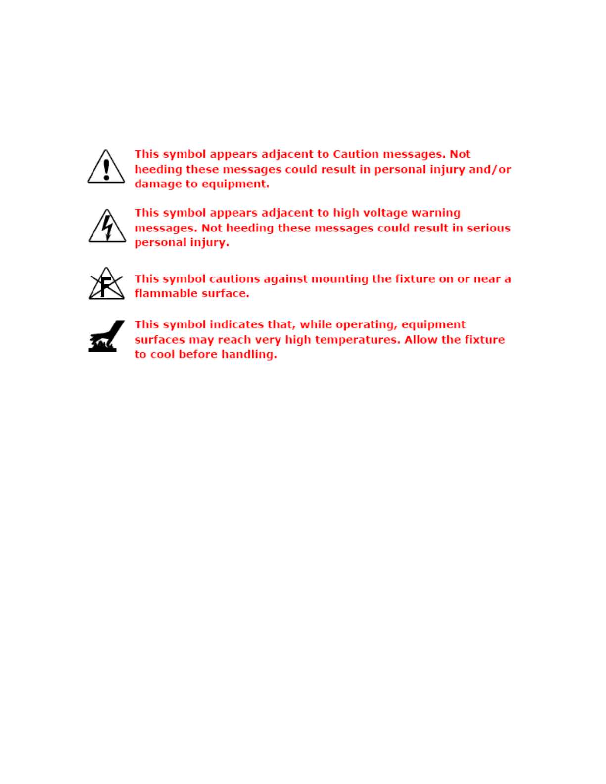
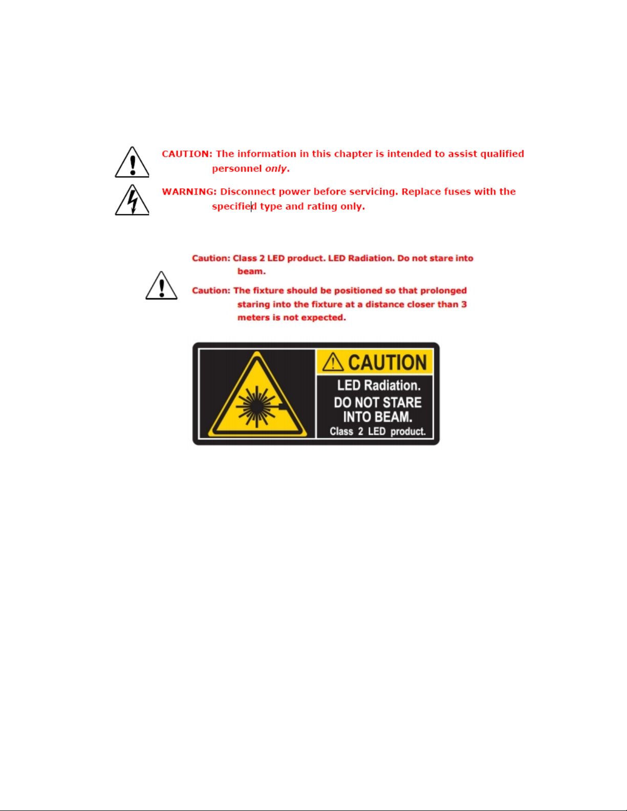
Important Safety Information
Instructions pertaining to continued protection against fire, electric shock, and injury to persons are found throughout this manual.
Please read all instructions prior to assembling, mounting, and operating this equipment.
The following international caution and warning symbolsappear in margins throughout this manual to highlight messages.
8
Page 13
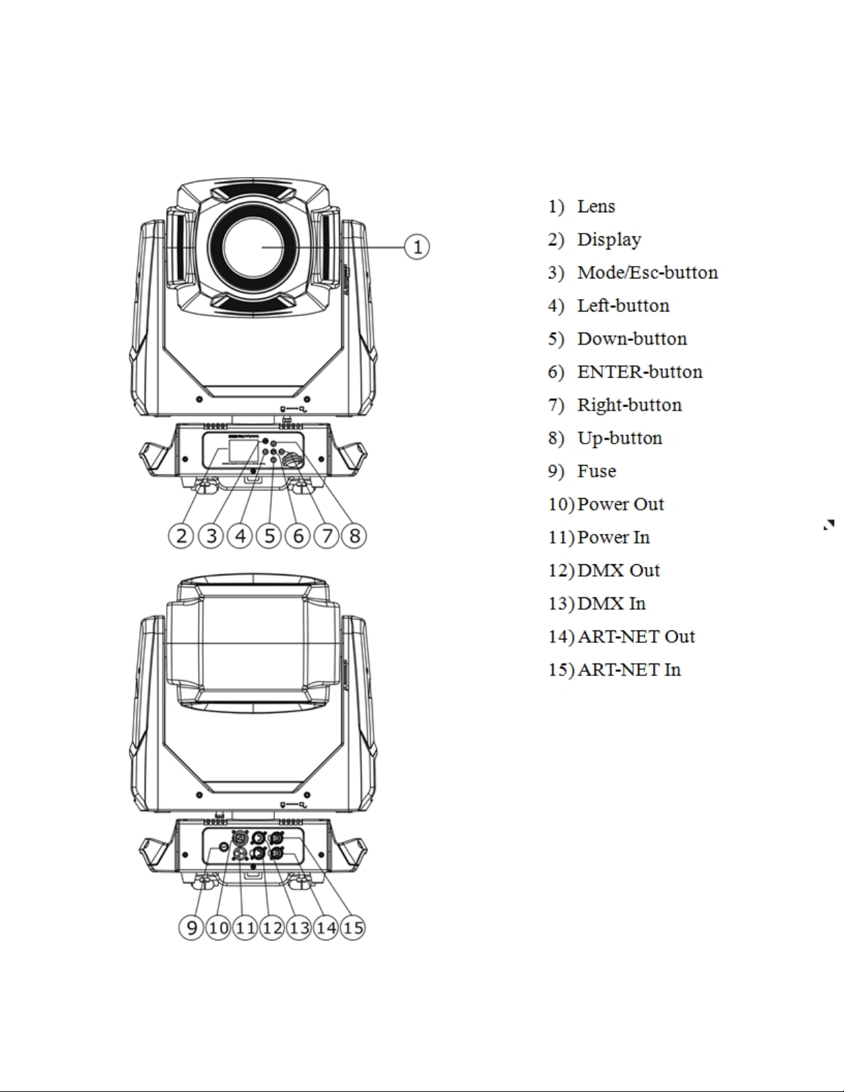
Fixture Overview
9
Page 14

This page intentionally left blank to ensure new
chapters start on right (odd number) pages.
10
Page 15

Features
l Modular Construction, Fast Ser vice Design
l ElectronicCooling System Control, Active Thermal Control
l Fan Modes- Normal / Continuous / Studio
l LED Type- 440W Bright White Engine
l LED Hours- 70% Luminous output, 50,000 hrs.
l Control Options- DMX 512 / RDM / Art- Net
l DMX Channels- 39
l 5-Pin DMX/RDM Connector
l Art-Net Connector
l “PowerCON TRUE1” Connector
l Pan and tilt movement: 8 and 16 bit r esolution, for smooth and precise motion
l Movement: Pan: 540°
l Movement: Tilt: 265°
l Max Speed Pan- 360 (seconds)- 2.27
l Max Speed Tilt- 180 (seconds)- 1.31
l Motorized focus
l Motorized Zoom - ~12-40
l Strobe/shutter: High speed shutter, 0-13 Hz or random strobe
l Dimmer intensity from 0%~100%
l Zoom - ~11deg - 35deg linear zoom
l Step-less Iris, 5-100% linear change iris, pulse iris effect
l Control boar d with full color LCD graphic displayand touch-keyboard
l Internal battery for displayand config. Enables users to enter menu for setting start address and other functions.
l Display: Can be changed 180° reverse to fit for different installation position.
l 7 Position color wheel, plus open white. Two directional rainbow effects
l CMY & CTO Variable Color Mixing for Infinite Color Possibilities
l Rotation gobo: 6 interchangeable, rotating gobos plus open
l Static gobo: 7 interchangeable, with variable speed Gobo shake and Gobo Indexing
l Animation flame effect
l Frost effect
l Position memory, auto correction after unexpected movement
l Software-upload by optional accessory dongle via DMX line
l Pan and Tilt Locks
l Road Case Included (Single)
11
Page 16

TECHNICAL SPECIFICATIONS
l Power supply: AC 100-240V~, 50/60Hz
l Power consumption: 700W
l Net weight: 30 KGS
12
Page 17
Safety Considerations
This device has left the factory in perfect condition. In order to maintain this condition and to ensure a safe operation, it is absolutely
necessary for the user to follow the safety instructions and warning notes written in this user manual.
Important:
Damages caused by the disregard of this user manual are no t subject to warranty. The dealer will not accept liab ility
for an y resulting d efects or problems.
13
Page 18

Warnings
l If the fixture has been exposed to temperature changes due to environmental changes, do not switch it on immediately. The
condensation that could form could cause internal damage. Leave the fixture switched off until it has r eached room temperature.
l This fixture fallsunder protection-Class I. Therefore it is essentialthat the device be ear thed.
l The electrical connection must carry out by a qualifiedperson.
l Make sure that the available voltage is within stated range.
l Make sure the power cord is never crimped or damaged by a sharp edge. Replace cable immediately if damaged, this work
must be done by an authorized dealer.
l Alwaysdisconnectfrom power, when the device is not in use or before cleaning it. Only handle the power cord by the plug.
Never pull out the plug by tugging the power cord.
l Don't project the beam onto combustible substances, this could cause a safety hazard and/or start a fire.
l Please be aware that damages caused by modifications to the fixture will void warranty.
l Keep away from children and non- professionals.
l Maintenance should be performed by a qualified individual.
l There are no serviceable parts inside the device. T he following points have to be considered when inspecting the fixture for
maintenance:
l Allscrews for installing the devicesor par ts of the device have to be tightly connected and must not be corr oded.
l Mechanically moved parts must not show any traces of wear and must not rotate freelywithout unbalance.
l The electric power supply cables must not show any damage, material fatigue or excessive dirt.
14
Page 19

General Guidelines
l This device is a lighting effect for professional use on stages, theaters, or other professional installations, etc., the device was
designed for indoor use only.
l This fixture is only allowed to be operated with the max alternating current (ACVoltage)which stated in the technicalspe-
cifications printed on the fixture.
l Lighting effects are not designed for permanent operation. Operation breaks ensure that the devicewill perform longer
without failure
l Do not shake the device. Avoid brute force when installing or operating the device.
l While choosing the installation-spot, please make sure that the device isnot exposed to extreme heat, moisture or dust.
Please don't project the beam onto combustible substances. The minimum distance between light-output fr om the projector
and the illuminated surface must be more than 0.5 meter or 1.6 ft.
l If you use the quick-lock cam to hang thisfixture, be sure to properly insert the fasteners in the quicklockholes corr ectly. Do
not hang this fixture without a safety cable.
l Operate the device onlyafter having familiarized with its functions. Do not permit operation by unqualified persons, damages
can occur due to unprofessional operation.
l Please use the original packaging if the deviceis to be transported.
l For safety reasons, please be aware that all modificationson the device are forbidden.
l If this device willbe operated in any way different to the one described in this manual, the product may suffer damages and
the warranty becomes void. Furthermore, misuse may lead to short-circuit, burns, electricshock, lamp explosion, crash, and
other damage to the fixture or persons.
15
Page 20

Installation Instructions
l The installation must always be secu red with a seco nd ary safety attachment, e.g. an appropriate safety
cable.
l Never stand directly belo w the device when mounting, removing or servicing the fixture.
l The operator has to make sure the safety and technical installations are app roved by an expert before tak-
ing u sing this fixture in the field for the first time.
l Fixed installat ion s must be inspected by a skilled person on a regular b asis.
l Overhead mounting requires extensive experience, including amongst others calculating working lo ad lim-
its, installation material being used, and periodic safety inspection of all inst allation material and th e device.
If you lack these qualificatio ns, d o not at tempt the installation yourself. Improper installation can result in
serious bod ily inju ry.
Attachment Instructions.
l Attach the Omega clamp on the bracket by tighten the M12 bolt on the bracket to the hole in the middle of the bracket.
l Insert the quick-lockfasteners of the bracket into the respective holes on the bottom of the fixture.
l Tighten the quick-lockfasteners fully clockwise.
l Installthe second Omega clamp.
l Attach the safety-cablethrough the holes on the bottom of the base. Attach to the trussing system or other safe fixation
point.
l Be sure the safety is fullylooped, the quick-linkis attached and fully tighten
l Inspect for complete attachment before lifting over-head
16
Page 21

Dimensional Drawings
Dims listed ar e mm and (inches)
17
Page 22

Mounting Orientations
Be sure this fixture is kept at least 0.5m (1.6ft) away from any flammable materials (decoration etc.). Always use and install the supplied safety cable as a safety measure to prevent accidental damage and/or injury in the event the clamp is improperly installed or
fails.
Overhead mounting requires extensive experience, including amongst others calculating working load limits, a detailed knowledge of
the installation materials being used, and per iodic safety inspection. This safety inspection must cover all installation material, trussing, hardwar e and the fixture. If you lack these qualifications, do not attempt the installation yourself. Improper installation can result
in sever injury and possible death if struck by a falling fixture.
18
Page 23

Linking Fixtures
The SolaSpot 1000 fixture operates on standard DMX512 linkcontrolled by a DMX console. The number of fixtures on a link will be
determined by the combined number of channelsrequired by all the fixtures. A SolaSpot 1000 fixture requires a 39 channel footprint
on a standard DMX512 link.Attach the fixture to the link using data-grade cable and 5- pin or 3-pin XLR cable connectors
Cable Connectors
The SolaSpot 1000 fixture accepts both 3-pin and 5-pin XLR cableconnectors. Cabling must have a male XLR connector on one end
of the cable and a female XLR connector on the other end.
19
Page 24

Con necting to the Link
To link one or more fixtures to a DMX controller:
l Con nect the male XLR connector of a DMX Data cable to the controller’s DMX Data Out con nector.
l Con nect the Data cable’s female XLR connector t o the Data In connector of the first (or n ext) fixture on the
DMX link.
l Con tin ue linking the remaining fixtures connecting a cable from t he Data Out connector of each f ixtu re to
the Data In connector of the next fixture on the link.
DMXTermination
For installations where the DMX cable has to run a long distance or is in an electrically noisy environment, a DMX terminator on the
last fixture of the link prevents data r eflection, which can corrupt the data communication on the link.
Terminate the linkby installing a 120 ohm, 1/4 watt (minimum) terminator in the fixture’s Data Out (female) cableconnector in the last
fixture on each DMX link.
20
Page 25

DMX Start Address
Allfixtures should be given a unique DMX starting addresswhen using a DMX signal, so that the correct fixture responds to the correct control signals. This DMX start addr ess is the channel number from which the fixture starts to “listen” to the digital control information sent out from the DMX controller. The setting of this start address is achieved by setting the correct number on the display
located on the base of the device.
You can set the same starting addr ess for all fixtures or a group of fixtures, or make use different addresses for each fixture individually.
If you set the same addr ess, all the units willstart to “listen” to the same control signal from the same channel number. In other words,
changing the settings of one channel willaffect all the fixtures simultaneously.
If you set a different address, each unit willstart to “listen” to the channel number you have set, based on the quantity of control channels of the unit. That means changing the settingsof one channel will affect only the selected fixture.
In the case of thisfixture, which isa 39 channel fixture, you should set the starting addressof the first unit to 1, the second unit to 40
(39+ 1), the third to 79(40+ 39), and so on.
21
Page 26

Fixture Control Board
The Control Board offers several features: you can simply set the starting address , run the pre-progr ammed program or make
other changes.
The main menu is accessed by pressing the [Mod e / ESC] button untilthe displayis visible.
Browse through the menu by pressing the [UP] button ,[Down] button , [Left] button or [Rig ht] button.
Press the [ Enter] button in order to select the desired menu.
You can change the selection by pressing the directional buttons. ie. the [UP] button ,[Down] button , [Left] button or [Rig ht ]
Confirm every selection by pressing the [Enter].
You can leave every mode by pressing the [Mode / Esc ]button.
The functions provided are described in the following sections. The menu item will disappear after 10 seconds after the last key
press. The functions provided are described in the following sections.
222324
Page 27

Page 28

Page 29

Control Board Functions
Add ress
With this function, you can adjust the desired DMX start address via the Control Board.
1.Access the main menu.
2.Tap the <Up/Down>button until “Address” is displayed.
3.PressENTER, the displaywillshow “Address”.
4.Tap the <Up/Down> button, the displaywill show “A001~AXXX”
5.PressENTER to confirm or press<MODE/ESC> to return to the main menu
Time Info
Current Time
With this function, you can displaythe running time from last power on. The displayshows “XXXX”, “XXXX” stands for the number of
hours. The counter is reset after power-off.
1.Tap <MODE/ESC> button, accessthe main menu,
l Tap the <Up/Down>button until"Info” isdisplayed. Press ENTER, the displaywillshow “Info.”.
l Tap the <Up/Down>button untilthe displaywill show “T ime Info.”.
l Press ENTER, the display will show “ Time Info.” .
2.Press<Up/Down>, the display willshow “Current Time”.
3.Press<ENTER>, the display will show “Current Time”.
4.The display will show “XXXX” (Hours) ;
5.Press<ENTER> to confirm or press <MODE/ESC> to return to the main menu.
Total Run Time
With this function, you can displaythe total running time of the fixture. The displayshows “XXXX”, “XXXX” stands for the number of
hours.
1.Tap <MODE/ESC> button, accessthe main menu,
l Tap the <Up/Down>button until"Info” isdisplayed. Press ENTER, the displaywillshow “Info.”.
l Tap the <Up/Down>button untilthe displaywill show “T ime Info.”.
l Press ENTER, the display will show “ Time Info.” .
2.Press<Up/Down>, the display willshow “T tl Life Hrs”.
3.Press<ENTER>, the display will show “Ttl Life Hrs”.
4.The display will show “XXXX” (Hours) ;
5.Press<ENTER> to confirm or press <MODE/ESC> to return to the main menu.
25
Page 30

Last Run T ime
With this function, you can displaythe last running time of the fixture. The display shows “XXXX”, “XXXX” stands for the number of
hours.
1.Tap <MODE/ESC> button, accessthe main menu,
l Tap the <Up/Down>button until"Info” isdisplayed. Press ENTER, the displaywillshow “Info.”.
l Tap the <Up/Down>button untilthe displaywill show “T ime Info.”.
l Press ENTER, the display will show “ Time Info.” .
2.Press<Up/Down>, the display willshow “Last Run Hrs”.
3.Press<ENTER>, the display will show “Last Run Hrs”.
4.The display will show “XXXX” (Hours) ;
5.Press<ENTER> to confirm or press <MODE/ESC> to return to the main menu.
LEDHrs
With this function, you can displaytotal running time of the LED. The displayshows “ XXXX”, “XXXX” stands for the number of hours.
1.Tap <MODE/ESC> button, accessthe main menu,
l Tap the <Up/Down>button until"Info” isdisplayed. Press ENTER, the displaywillshow “Info.”.
l Tap the <Up/Down>button untilthe displaywill show “T ime Info.”.
l Press ENTER, the display will show “ Time Info.” .
2.Press<Up/Down>, the display willshow “LEDHours”.
3.Press<ENTER>, the display will show “LEDHours”.
4.The display will show “XXXX” (Hours) ;
5.Press<ENTER> to confirm or press <MODE/ESC> to return to the main menu.
Timer PIN
With this function, you can displaythe timer password. The time password is 038.
1.Tap <MODE/ESC> button, accessthe main menu,
l Tap the <Up/Down>button until"Info” isdisplayed. Press ENTER, the displaywillshow “Info.”.
l Tap the <Up/Down>button untilthe displaywill show “T ime Info.”.
l Press ENTER, the display will show “ Time Info.” .
2.Press<Up/Down>, the display willshow “T imer PIN”.
3.Press<ENTER>, the display will show “Timer PIN”, the time password is 038.
4.Press<ENTER> to confirm or press <MODE/ESC> to return to the main menu.
26
Page 31

Clr Last Run
With this function, you can clear last run time of the fixture. The display shows “OFF” or “ON”, Press “Enter” to confirm.
1.Tap <MODE/ESC> button, accessthe main menu,
l Tap the <Up/Down>button until"Info” isdisplayed. Press ENTER, the displaywillshow “Info.”.
l Tap the <Up/Down>button untilthe displaywill show “T ime Info.”.
l Press ENTER, the display will show “ Time Info.” .
2.Press<Up/Down>, the display willshow “Clr Last Run”.
3.At “T imer Password” menu input a correct password, pr ess< ENTER>, the displaywill show “Clr Last Run”,
4.The display will show “OFF”or“ON” .
5.Press<ENTER> to confirm or press <MODE/ESC> to return to the main menu.
Timer PIN
With this function, you can displaythe timer password. The time password is 038.
1.Tap <MODE/ESC> button, accessthe main menu,
l Tap the <Up/Down>button until"Info” isdisplayed. Press ENTER, the displaywillshow “Info.”.
l Tap the <Up/Down>button untilthe displaywill show “T ime Info.”.
l Press ENTER, the display will show “ Time Info.” .
2.Press<Up/Down>, the display willshow “LEDTime PIN” .
3.Press<ENTER>, the display will show “LEDTime PIN”, the time password is 038.
4.Press<ENTER> to confirm or press <MODE/ESC> to return to the main menu.
Clean LEDTime
With this function, you can clear the running time of the LED engine (this should not be done unless an engine has been replaced)
1.Tap <MODE/ESC> button, accessthe main menu,
l Tap the <Up/Down>button until"Info” isdisplayed. Press ENTER, the displaywillshow “Info.”.
l Tap the <Up/Down>button untilthe displaywill show “T ime Info.”.
l Press ENTER, the display will show “ Time Info.” .
2.Press<Up/Down>, the display willshow “Clean LEDTime”.
3.At “T imer Password” prompt, input a correct password, press<ENTER>, the display willshow “Clean LEDTime”,
4. The display will show "Off" or "On"
5.Press<ENTER> to confirm or press <MODE/ESC> to return to the main menu.
27
Page 32

Value Displayed
NONE
With this function, you can choose to turn off display of DMX Control channel values.
1.Tap <MODE/ESC> button, accessthe main menu,
l Tap the <Up/Down>button until“Info” is displayed.
l Press ENTER, the display will show “ Info”.
2.Press<Up/Down>, the display willshow “Value Disp”.
3.Press<ENTER>, the display will show “Value Disp”.
4.The display show “None”.
5.Press<ENTER> to confirm or press <MODE/ESC> to return to the main menu.
ALL , PAN
With this function you can displaythe DMX 512 value of each channel. If allis selected, the display willautomatically show a channel
that is changing.
1.Tap <MODE/ESC> button, accessthe main menu,
l Tap the <Up/Down>button until“Info” is displayed.
l Press ENTER, the display will show “ Info”.
2.Tap the <Up/Down>button until “Value Disp” is displayed.
3.PressENTER, the displaywillshow “Value Disp”.
4.Tap the <Up/Down> button, choose each channel.
5.PressENTER to confirm or press<MODE/ESC> to return to the main menu.
Head Temp.
With this function you can displaythe temperature on the display board of the base ( near CMY-filter) in Celsius.
1.Tap <MODE/ESC> button, accessthe main menu,
l Tap the <Up/Down>button until“Info” is displayed.
l Press ENTER, the display will show “ Info”.
2.Press<Up/Down>, the display willshow “Head Temp.”.
3.Press<ENTER>, the display will show “Head Temp.”.
4.The display show “XXX °C/ °F”.
5.Press<ENTER> to confirm or press <MODE/ESC> to return to the main menu.
Fan Speed
With this function you can displaythe RPMof various fans inside the fixture.
1.Tap <MODE/ESC> button, accessthe main menu,
l Tap the <Up/Down>button until“Info” is displayed.
l Press ENTER, the display will show “ Info”.
2.Press<Up/Down>, the display willshow “F an Speed.”.
3.Press<ENTER>, the display will show “Fan 1: xxxRPM", Fan 2: xxxRPM" ....”
4.Press<ENTER> to confirm or press <MODE/ESC> to return to the main menu.
28
Page 33

Ethernet IP
With this function, you can displaythe IPaddress of the fixture.
1.Tap <MODE/ESC> button, accessthe main menu,
l Tap the <Up/Down>button until“Info” is displayed.
l Press ENTER, the display will show “ Info”.
2.Press<Up/Down>, the display willshow “Ether net IP”.
3.Press<ENTER>, the display will show “Ethernet IP”.
4.The display show “Ethernet IPxxx.xxx.xxx.xxx”.
5.Press<ENTER> to confirm or press <MODE/ESC> to return to the main menu.
Soft ware Ver
With this function, you can displaythe software version of the device.
1.Tap <MODE/ESC> button, accessthe main menu,
l Tap the <Up/Down>button until“Info” is displayed.
l Press ENTER, the display will show “ Info”.
2.Press<Up/Down>, the display willshow “Software Ver”.
3.Press<ENTER>, the display will show “Software Ver”.
4.The display show “Ver x.x”.
5.Press<ENTER> to confirm or press <MODE/ESC> to return to the main menu.
Set
Statu s
No DMX Mode
With this function, when DMX is not connected, it runs automatic, closed, hold and music. T he default is hold.
1.Tap <MODE/ESC> button, accessthe main menu,
l Tap the <Up/Down>button until“Set” isdisplayed.
l Press ENTER, the display will show “ Set”.
l Tap the <Up/Down>button untilthe displaywill show “Status”.
l Press ENTER, the display will show “ Status”.
2.Press<Up/Down>, the display willshow “No DMX Mode”.
3.Press<ENTER>, the display will show “No DMX Mode”.
4.The display show “Hold”, Press <Up/Down>, the display will show “Close”, “Auto”, “Music”.
5.Press<ENTER> to confirm or press <MODE/ESC> to return to the main menu.
29
Page 34

Pan Reverse
With this function you can reverse the Pan- movement.
1.Tap <MODE/ESC> button, accessthe main menu,
l Tap the <Up/Down>button until“Set” isdisplayed.
l Press ENTER, the display will show “ Set”.
l Tap the <Up/Down>button untilthe displaywill show “Status”.
l Press ENTER, the display will show “ Status”.
2.Press<Up/Down>, the display willshow “Pan Reverse”.
3.Press<ENTER>, the display will show “Pan Reverse”.
4.The display show “OFF ”, Press <Up/Down>, the displaywill show “ON” .
5.Press<ENTER> to confirm or press <MODE/ESC> to return to the main menu.
Tilt Reverse
With this function you can reverse the T ilt-movement.
1.Tap <MODE/ESC> button, accessthe main menu,
l Tap the <Up/Down>button until“Set” isdisplayed.
l Press ENTER, the display will show “ Set”.
l Tap the <Up/Down>button untilthe displaywill show “Status”.
l Press ENTER, the display will show “ Status”.
2.Press<Up/Down>, the display willshow “T ilt Reverse”.
3.Press<ENTER>, the display will show “Tilt Reverse”.
4.The display show “OFF ”, Press <Up/Down>, the displaywill show “ON” .
5.Press<ENTER> to confirm or press <MODE/ESC> to return to the main menu.
Encoders
With this function, you can change the feedback of the pan movement or tilt movement.
1.Tap <MODE/ESC> button, accessthe main menu,
l Tap the <Up/Down>button until“Set” isdisplayed.
l Press ENTER, the display will show “ Set”.
l Tap the <Up/Down>button untilthe displaywill show “Status”.
l Press ENTER, the display will show “ Status”.
2.Press<Up/Down>, the display willshow “Encoders”.
3.Press<ENTER>, the display will show “Encoders”.
4.The display show “ON”, Press <Up/Down>, the display will show “OFF” .
5.Press<ENTER> to confirm or press <MODE/ESC> to return to the main menu.
30
Page 35

Pan/Tilt Spd
With this function, you can select modes from 1 to 4.
1.Tap <MODE/ESC> button, accessthe main menu,
l Tap the <Up/Down>button until“Set” isdisplayed.
l Press ENTER, the display will show “ Set”.
l Tap the <Up/Down>button untilthe displaywill show “Status”.
l Press ENTER, the display will show “ Status”.
2.Press<Up/Down>, the display willshow “Pan/T ilt Spd”.
3.Press<ENTER>, the display will show “Pan/Tilt Spd”.
4.The display show “Speed 1” , Press <Up/Down>, the display willshow “Speed 2” , “Speed 3”, “Speed 4”.
5.Press<ENTER> to confirm or press <MODE/ESC> to return to the main menu.
Hibernatio n ——Standby mode
The lamp and step motors willbe power off if the fixture stay without DMX signal for 15 mins (Factory default). The fixture will Home
once it receive DMX signal again.
1.Tap <MODE/ESC> button, accessthe main menu,
l Tap the <Up/Down>button until“Set” isdisplayed.
l Press ENTER, the display will show “ Set”.
l Tap the <Up/Down>button untilthe displaywill show “Status”.
l Press ENTER, the display will show “ Status”.
2.Press<Up/Down>, the display willshow “Hibernation”.
3.Press<ENTER>, the display will show “Hibernation”.
4.The display show “15M” , Press <Up/Down>, the display willshow “01M”,“02M” …. “99M” or“ OFF ”.
5.Press<ENTER> to confirm or press <MODE/ESC> to return to the main menu.
Defo gg er
With this function, you can select ON / OFF, or OnPwr.
1.Tap <MODE/ESC> button, accessthe main menu,
l Tap the <Up/Down>button until“Set” isdisplayed.
l Press ENTER, the display will show “ Set”.
l Tap the <Up/Down>button untilthe displaywill show “Defogger”.
l Press ENTER, the display will show “ Defogger”.
2.Press<Up/Down>, the display willshow “Defog ON”.
3.Press<ENTER>, the display will show “Pan/Tilt Spd”.
4.The display show “Speed 1” , Press <Up/Down>, the display willshow “Speed 2” , “Speed 3”, “Speed 4”.
5.Press<ENTER> to confirm or press <MODE/ESC> to return to the main menu.
31
Page 36

Select Inp ut
1.Tap <MODE/ESC> button, accessthe main menu,
l Tap the <Up/Down>button until“Set” isdisplayed.
l Press ENTER, the display will show “ Set”.
2.Press<Up/Down>, the display willshow “Select Input”.
3.Press<ENTER>, the display will show “Select Input” .
4.The display show “DMX Only”, Press <Up/Down>, the display will show “Art-Net On IP02”,“Art-Net On IP10”.
5.Press<ENTER> to confirm or press <MODE/ESC> to return to the main menu.
Set Universe
1.Tap <MODE/ESC> button, accessthe main menu, then tap the <Up/Down>button until“Set” isdisplayed. Press ENTER, the display will show “Set”.
2.Press<Up/Down>, the display willshow “Set Universe”.
3.Press<ENTER>, the display will show “Set Universe”.
4.The display show “000~255”.
5.Press<ENTER> to confirm or press <MODE/ESC> to return to the main menu.
Service PIN
Service PIN——The Password for thisfunction is “50”.
RDM PID—— To take advantage of the technicalcapabilities of the RDM system, each fixture must have a unique RDM PID, this
unique identifying number isused by the controller to manage an individualfixture. There cannot be duplicate RDM PID on the same
DMX cable run, this willresult in a data collision, and the controller may or may not notifyof this issue. Ensure that all fixtures have a
unique RDM PID if RDM functionalityis to be used.
If DMX splitters are used and RDM control is to be used, these splitters must support RDM.
The number and type of RDM parameters depend on the RDM controller being used.
To Set the RDMPID
Navigate to: Set -> Service Settings -> Service PIN Press <UP> button to select 050 and press <ENTER.>
Navigate to RDM PID: Press the <UP> button to select unique ID’s for each fixture and press <ENTER.>
Disp.Settin g
Shut of f Time
With this function you can shut off the color LCD display after 2 to 60 minutes. Tur n the encoder in order to select the desired shut off
time. T he default is 2 minute.
32
Page 37

Flip Display
With this function you can rotate the displayby 180°.
1.Tap <MODE/ESC> button, accessthe main menu,
l Tap the <Up/Down>button until“Set” isdisplayed.
l Press ENTER, the display will show “ Set”.
2. Tap the <Up/Down>button until the display will show “Disp.Setting”.
3. Press ENTER, the display willshow “Disp.Setting”.
2.Press<Up/Down>, the display willshow “F lip Display”.
3.Press<ENTER>, the display will show “Flip Display”.
4.The display show “OFF ”, Press <Up/Down>, the displaywill show “ON” .
5.Press<ENTER> to confirm or press <MODE/ESC> to return to the main menu.
Key Lock
With this function you can activate the automatic keylockstatus. If this function is activated, the keys will be locked automatically after
exiting the edit mode for 15 seconds. keeping press the<MODE/ESC> key for 3seconds if you do not need this function.
1.Tap <MODE/ESC> button, accessthe main menu,
l Tap the <Up/Down>button until“Set” isdisplayed.
l Press ENTER, the display will show “ Set”.
2.Press<Up/Down>, the display willshow “Key Lock”.
3.Press<ENTER>, the display will show “Key Lock”.
4.The display show “ON”, Press <Up/Down>, the display will show “OFF” .
5.Press<ENTER> to confirm or press <MODE/ESC> to return to the main menu.
Temp. C/F
With this function, Display the temperature for Celsiusor Fahrenheit.
1.Tap <MODE/ESC> button, accessthe main menu,
l Tap the <Up/Down>button until“Set” isdisplayed.
l Press ENTER, the display will show “ Set”.
2.Press<Up/Down>, the display willshow “T emp. C/F ”.
3.Press<ENTER>, the display will show “Temp. C/F” .
4.The display show “Celsius”, Press <Up/Down>, the display willshow “Fahrenheit”.
5.Press<ENTER> to confirm or press <MODE/ESC> to return to the main menu.
33
Page 38

Reset Default
With this function, you can reset all settingsto factory default.
1.Tap <MODE/ESC> button, accessthe main menu,
l Tap the <Up/Down>button until“Set” isdisplayed.
l Press ENTER, the display will show “ Set”.
2.Press<Up/Down>, the display willshow “ResetDefault”.
3.Press<ENTER>, the display will show “ResetDefault”.
4.The display show “OFF ”, Press <Up/Down>, the displaywill show “ON” . (ON = Restore to Factory Default)
5.Press<ENTER> to confirm or press <MODE/ESC> to return to the main menu.
Test
Home
With this function you can reset the fixture, and r eset the Control Boards. You can select the different reset functions by choosing different items in the menu.
1.Tap <MODE/ESC> button, accessthe main menu,
l Tap the <Up/Down>button until“Test” is displayed.
l Press ENTER, the display will show “ Test”.
2.Tap the <Up/Down>button until the display will show “ Home” . Press ENTER, the display will show “Home”.
3.The display show “All”, Press <Up/Down>, the displaywillshow “Pan&Tilt”,"Colors", “Shutter”, “ Others”.
4.Press<ENTER> to confirm or press <MODE/ESC> to return to the main menu.
Test Channel
With this function you can test each channel on its (correct) function.
1.Tap <MODE/ESC> button, accessthe main menu,
l Tap the <Up/Down>button until“Test” is displayed.
l Press ENTER, the display will show “ Test”.
2.Press<Up/Down>, the display willshow “T est Channel”.
3.Press<ENTER>, the display will show “Test Channel”.
4.The display will show “Pan Moving” first channel, Press <Up/Down>, to choose another channel.
5.Press<ENTER> to confirm or press <MODE/ESC> to return to the main menu.
Manual Ctrl.
With this function, you can adjust the fixture more easily. All effects will be canceled, the shutter opens and the dimmer intensity will be
set to 100 %. With the individual functions, you can focus the light on a flat surface (wall) and perform various fixture adjustments.
1.Tap <MODE/ESC> button, accessthe main menu,
l Tap the <Up/Down>button until“Test” is displayed.
l Press ENTER, the display will show “ Test”.
2.Press<Up/Down>, the display willshow “Manual Ctrl.”.
3.Press<ENTER>, the display will show “Manual Ctrl.”.
4.The display show “PAN=XXX”.
5.Press<ENTER> to confirm or press <MODE/ESC> to return to the main menu.
34
Page 39

Calibration
With this function, you can calibrate and adjust the effect wheels to their correct positions.The password is 050.
1.Tap <MODE/ESC> button, accessthe main menu,
l Tap the <Up/Down>button until“Test” is displayed.
l Press ENTER, the display will show “ Test”.
2.Press<Up/Down>, the display willshow “Calibration”.
3.Press<ENTER>, the display will show “Calibration”.
4.The display show “Password=XXXX”.
5.Press<ENTER> to confirm or press <MODE/ESC> to return to the main menu.
Preset
In this menu, user can select different channels list by different sequence:
For example, after the user enter thismanual, if select Auto Program = CH 22, means in this User’s mode, the “ Dimmer” is in Channel 16.
PlayBack
DMX Con trol
To set the fixture to be controlled via DMX.
1.Tap <MODE/ESC> button, accessthe main menu,
l Tap the <Up/Down>button until“Preset” is displayed. PressENTER, the displaywillshow “Preset”.
l Tap the <Up/Down>button untilthe displaywill show “PlayBack”.
l Press ENTER, the display will show “ PlayBack”.
2.Tap the <Up/Down>button until “DMX Contr ol” is displayed.
3.PressENTER, the displaywillshow “DMX Control”.
4.Tap the <Up/Down> button, choose each channel.
5.PressENTER to confirm or press<MODE/ESC> to return to the main menu.
Set To Slave
With this function, you can define the device as slave.
1.Tap <MODE/ESC> button, accessthe main menu,
l Tap the <Up/Down>button until“Preset” is displayed. PressENTER, the displaywillshow “Preset”.
l Tap the <Up/Down>button untilthe displaywill show “PlayBack”.
l Press ENTER, the display will show “ PlayBack”.
2.Tap the <Up/Down>button until “Set To Slave” is displayed.
3.PressENTER, the displaywillshow “Set To Slave”.
4.Tap the <Up/Down> button, the displaywill show “Slave1”, ”Slave2”, ”Slave3”.
5.PressENTER to confirm or press<MODE/ESC> to return to the main menu.
35
Page 40

Auto Program
With this function, you can run the internal program. You can selectthe desired program under “Select program”. You can set the
number of stepsunder “ Edit program”. You can edit the individual scenes under “Edit scenes”. With this function, you can run the individualscenes manually or automatically, with the adjusted Step- Time.
1.Tap <MODE/ESC> button, accessthe main menu,
l Tap the <Up/Down>button until“Preset” is displayed. PressENTER, the displaywillshow “Preset”.
l Tap the <Up/Down>button untilthe displaywill show “PlayBack”. Press ENT ER, the display will show “PlayBack”.
2.Tap the <Up/Down>button until “Auto Program” is displayed.
3.PressENTER, the displaywillshow “Auto Program” .
4.Tap the <Up/Down> button, the displaywill show “Master1”, ” Alone”.
5.PressENTER to confirm or press<MODE/ESC> to return to the main menu.
Music Ct rl.
With this function, you can run the internal program sound-controlled.
1.Tap <MODE/ESC> button, accessthe main menu, then tap the <Up/Down>button until“Preset” is displayed. PressENTER, the
display will show “Preset”. Tap the <Up/Down>button until the display will show “ PlayBack”. Press ENTER, the displaywill show
“PlayBack”.
2.Tap the <Up/Down>button until “MusicCtrl.” is displayed.
3.Press<ENTER>, the display will show “Music Ctrl.”.
4.Tap the <Up/Down> button, the displaywill show “Master”, ” Alone”.
5.Press<ENTER> to confirm or press <MODE/ESC> to return to the main menu.
Select Prog.
With this function, you can select the program for the Program Run.
Edit Prog .
With this function, you can edit the internal programs.
Edit Scenes
With this function, you can edit the scenes of the internal programs.
Rec. Controller
This fixture features an integrated DMX-recorder by which you can transmit the programmed scenes from your DMX-controller to
the fixture. Adjust the desired scene numbers via the encoder (from – to) . When you callup the scenes at your controller, they will
automaticallybe transmitted to the moving head.
Example:
A Master unit can send up to 3 different data groups to the Slave units, i.e. a Master unit can start 3 different Slave units, which run 3
different programs. The Master unit sends the 3 program parts in a continuous loop.
36
Page 41

To start an Auto Program :
1. Slave-Sett ing :
• Select “Function Mode” by navigating with the arrow key.
• Press the Enter button to confirm.
• Select “Set to slave” by navigating with the arrow key.
• Press the Enter button to confirm.
• Select “Slave 1”, “Slave 2” or “Slave 3”.
• Press the Enter button to confirm.
• Press the MODE/ESC button in order to return to the main menu.
2. Automatic Program Ru n
• Select “Function Mode” by navigating with the arrow key.
• Press the Enter button to confirm.
• Select “Auto Program” by navigating with the arrow key.
• Press the Enter button to confirm.
• Select “Master” or “Alone”. The selection "Alone" means Stand Alone-mode and "Master" that the device is defined as master.
• Press the Enter button to confirm.
• Press the MODE/ESC button in order to return to the main menu.
3. Program selection for Auto Pro Part
• Select “Edit program” by navigating with the arrow key.
• Press the Enter button to confirm.
• Select “Select programs” by navigating with the arrow key.
• Press the Enter button to confirm.
• Select “Auto Pro Part 1”, “Auto Pro Part 2” or “Auto Pro Part 3”, and then select which Slave program is to be sent. Selection “Part
1” means, that the Slave unit runs the same program as the master units.
• Press the Enter button to confirm.
• Press the MODE/ESC button in order to return to the main menu.
4. Program selection for Edit Program
• Select “Edit program” by navigating with the arrow key.
• Press the Enter button to confirm.
• Select “Edit program” by navigating with the arrow key.
• Press the Enter button to confirm.
• Select the desired pr ogram. With this function you can edit specific scenes into a specific program.
• Press the Enter button to confirm.
• Press the MODE/ESC button in order to return to the main menu.
37
Page 42

5. Automatic Scene Recording
• Select “Edit program” by navigating with the arrow key.
• Press the Enter button to confirm.
• Select “Edit scenes” by navigating with the arrow key.
• Select the desired scene numbers. You can program a maximum number of 250
• Press the Enter button to confirm.
• Press the MODE/ESC button in order to return to the main menu.
Example:
Program 2 includesscenes:10, 11, 12, 13
Program 4 includesscenes:8, 9, 10
Program 6 includesscenes:12, 13, 14, 15
Auto Pro Part 1 isProgram 2;
Auto Pro Part 2 isProgram 4;
Auto Pro Part 3 isProgram 6
The 3 Slave groups run the Auto Program in certain time segments, as shown in the following picture:
38
Page 43

Preset Programming and Playback
SolaSpot 1000 fixtures can be programmed through the on board menu system using Preset Programming. This
section describes how to program your fixtures for stand-alone operation using the on-boar d memory in each fixture to create and store scenes.
Preset Programming Overview
Presets are built fr om combining scenes into pr ograms and then assigning the programs to Program Partitions for
playbackby a fixture designated as the Master and, if desired, groups of slave fixtures assigned to a Program Partition. SolaSpot 1000 fixtures ship with factory programmed scenesand programs ready for you to use or edit.
Creatin g presets con sists of performing the fo llowing steps:
l Designating a fixture as the Master
l Selecting/Editing Scenes
l Sequencing Scenes into Programs
l Sequencing Programs into Program Partitions
l Configuring slave fixtures on the link to playback a Program Partition from the master
Navigating to the Preset Menu
To enter the Preset Menu:
l Press the [ MODE/ESC] button to enter the first level of the menu system. The displaywillshow Address and Info as the first
two options in the top menu level.
l The r ed star [*] indicates the current menu.
l Using the [ UP],[DOWN] buttons, scrollto Preset.
l Press the [ Enter] button to select.
Master and Slave
The following example shows the relationship between scenes, programs and partitions
programmed on the Master and how slave groups are assigned.
l Groups of scenes are edited into Programs 1– 6 on the fixture designated as Master
l Program 2 is assigned to Part 1
l Program 4 is assigned to Part 2
l Program 6 is assigned to Part 3
l Fixtures assigned as Slave 1 playback Part 1
l Fixtures assigned as Slave 2 playback Part 2
l Fixtures assigned as Slave 3 playback Part 3
l Scene 4 Scene 5 Scene 6 Scene 7
39
Page 44

Preset Menu
Playback Settings
Preset progr amming requires one fixture to act as the Master. All other SolaSpot 1000 fixtures on the link can then
be set as laves to playback the Master presets. Slave fixtures receive all their preset parameter and timing information from the master fixture. Playback settings designate a fixture as a master or a slave and also allow you to
revert from Auto Programming to DMX control from console or set a fixture in Master or standalone mode for audio
control.
Automatic Prog ram Run
This Playback option lets you designate a fixture to playback in Standalone mode or as a Master. Alon e is the default setting.
To designate a fixture as a Master:
l Navigate to and select the Preset menu.
l Use the[UP],[DOWN] buttons to scroll to Playback menu and press [Enter]to select.
40
Page 45

l Use the[UP],[DOWN] buttons to scroll to Auto Program menu and press [Enter]to select.
l Use the [UP],[DOWN]buttons to scroll to Master and press [Enter]to select. Your choicewill be shown in the display.
Set to Slave
After a preset program is defined on a Master fixture, other SolaSpot 1000 fixtures on the same DMX link can be designated laves to
playbackProgram Part 1, 2 or 3 as defined on the Master fixture.
To designate a fixture as a Slave:
l Navigate to and select the Preset menu.
l Use the [UP],[DOWN]buttons to scroll to Playb ack menu and press [Enter]to select.
l Use the [UP],[DOWN]buttons to scroll to Set T o Slave menu and press [Ent er]to select.
l Use the [UP],[DOWN]buttons to scroll to Slave1, Slave2, or Slave3 option and press [Enter]to select.
l Your choice willbe shown in the display.
DMX Con trol
Selecting this option reverts the function from Au to Program ( Preset Programming) to DMX Receive (console control). Selecting
this option will take you back to the menu startup screen wher e DMX Receive willbe displayed as the currentlyselected function.
Music Co ntrol
This Playback option lets you designate a fixture to playback scenes based on audio triggers detected by the internal microphone in
stand alone or as a Master. Alone is the default setting.
Edit Scenes
A parameter is a fixture attribute that can be controlled to modifythe light beam in terms of color, beam quality and pattern, intensity,
or focus (position). DMX programming assigns a DMX value to each of the fixture’s parameters. A scene is one combination of parameter settings.
SolaSpot 1000 fixtures provide 250 pr e-pr ogrammed scenes you can use or edit to build a preset pr ogram. The first 64 scenes ave
factory created settings which can be edited as desired.
Edit Scene Parameters
The Edit Scenes option lets you select a DMX value for any of the 39 parameters in the SolaSpot 1000 DMX protocol.
To ed it the DMX parameters in a scen e:
l Navigate to and select the Preset menu as shown on page 35.
l Use the [UP],[DOWN]buttons to scroll to the Edit Scenes option and press [Enter]to select.
l Use the [UP],[DOWN]buttons to scroll to the Scene number you wish to build on from 1-250 and press to [Ent er]select.
l Use the [UP],[DOWN]buttons to scroll to the parameter you wish to edit (Pan, T ilt, MSpeed, Color Wheel, etc.) and press to
[Ent er]select.
Use the [UP],[DOWN]buttons to scroll to a new DMX value for the parameter you have selected and press[Enter] to select. This
takes you back to parameter options. Continue through all parameters until your desired look is complete.
l When you are finished selecting all parameter valuesfor a particular Scene, press the [MODE/ESC]button to retur n to the
Preset levelmenu.
41
Page 46

Edit Scene Time
This Scene Edit option lets you set the scene time in seconds from 00.2s–99.9s. The default value is 00.3s. Thisvalues determines
how long the scene willplay before the next scene is triggered.
Set Fade Time
This Scene Edit option lets you set a fade time value from 000–255. T his values determines the crossfade time applied to parameters
once the scene is tr iggered.
Set Input b y Out
This Scene Edit option allows you to capture the parameter valuesfor a scene from DMX input into the fixture. Once you create a look
from a DMX consoledo the following:
l Navigate to and select the Preset menu as shown on page 35.
l Use the [UP],[DOWN]buttons to scroll to the Edit Scenes option and press [Enter]to select.
l Use the [UP],[DOWN]buttons to scroll to the Scene number you wish to build on from 1-250 and press to [Ent er]select.
l Use the [UP],[DOWN]button to scroll to the Input by Out and [Enter]pr ess to select.
l The scene will record the current parameter values being input via DMX.
l When you are finished capturing DMX into a scene, press [En ter]to return to the main menu.
Edit Program
This preset menu option lets you select from 10 factory set progr ams to edit. You can set up to 64 Scenesin a sequence of Steps for
each program. You can also test the program at any time by selecting Program Test to playback the program as it is currently
defined.
To edit a program:
l Navigate to and select the Preset menu.
l Use the [UP],[DOWN] buttons to scroll to Edit Prog. menu and press [Enter]to select.
l Use the [UP],[DOWN] buttons to scroll to a program from Program 1–Program 10 and press [ Enter]to select.
l Use the [UP],[DOWN]buttons to scroll to the Step in the program you want to edit from Step 1 to Step 64 and press
[Ent er]to select. The display will show which scene is currently assigned to that step.
l Use the [UP],[DOWN]buttons to scroll to the scroll to the scene you want to assign to the step and pr ess [Enter]to select.
l When you have assigned all the steps you want, select End and press [Enter]to save the program.
Select Program
This preset option lets you assign a Preset Program to one of three Program Partitions. A fixture assigned as a Slave can playback
any Program Par tition defined by the Master fixture.
Note: The Master f ixtu re can on ly playb ack Program Partition 1
To assign a pr ogram to each Program Partition:
l Navigate to and select the Preset menu as shown on page 35.
l Use the [UP],[DOWN]buttons to scroll to Select Prog menu and press [Enter]to select. Each Program Part, has 10 preset
programs.
l Use the [UP],[DOWN]buttons to scroll to Prog. Part 1 and press [Enter]to select.
l Use the [UP],[DOWN]buttons to scroll to a pr ogram from Prog ram 1–Program 10 and press [Ent er]to select the program
you want to include in the Progr am Part.
42
Page 47

l Use the [UP],[DOWN]buttons to scroll to Prog. Part 2 and press [Enter]to select.
l Use the [UP],[DOWN]buttons to scroll to a pr ogram from Prog ram 1–Program 10 and press[Ent er] to select the program
you want to include in the Progr am Part.
l Use the [UP],[DOWN]buttons to scroll to Prog. Part 3 and press [Enter]to select.
l Use the [UP],[DOWN]buttons to scroll to a pr ogram from Prog ram 1–Program 10 and press [Ent er]to select the program
you want to include in the Progr am Part.
l Press the [ Mode / ESC] button to return to the main menu.
Scenes Input
This function allows you to capture multiple scenes from DMX values input to the fixture. You first
define the number of scenes to capture and then each time a DMX value changes, a different
scene will be captured.
1.Navigate to and select the Preset menu.
2.Use the buttons to scroll to the Scenes Input option and pr ess to select.
3.Use the buttons to set the starting scene number.
4.Use the buttons to set the ending scene number. With each change of any DMX value, the capturing scene willadvance to the
next one in the r ange.
5.When all scenes have been recorded, the scenes input menu will automatically exit.
Note: Dur ing Scenes Input recording, the SolaSpot 1000 does not playback the DMX input, it only captures it. You must edit or playback the scenes after recording to see the results. It is best to prepare the scenes on a DMX controller with a zero crossfade for all
parameters between each step. Remember any change of a DMX value will advance to the next scene to capture.
43
Page 48

DMX Control Protocol
The most current DMX Control Protocol data for the SolaSpot 1000 can be found on the High End Systems, Inc. website
https://www.highend.com/SolaSpot1000-DMXProtocol.
The following data is current as of protocolversion 1.3, revision date July 13, 2017.
4445464748
Page 49

Page 50

Page 51

Page 52

Page 53

Protocol Notes
1. Continuous mode should take quickest path from 255-0, and 0-255.
l Continuous mode color wheel aperture centers
2. 63 Discrete multi step LED animations to be defined later. These willrequire macro speed and x fade channels. The macros
willoperate independently. The Xfade and speed channels act as multipliers of the programmed speed in the discrete
macro steps.
Speed / X fade channel operation
l 0 stops playback or crossfade
l 1-127 decreases playback speed / crossfade time ( * <1)
l 128 playbackor cross fade speed is as progr ammed (*1)
l 129-255 increases playbackspeed / crossfade time (* >1)
3. Fan control modes are not retentive. When the fixture is turned off it will default back to Standard mode.
49
Page 54

Error Codes
When you turn on the fixture, it will complete a start-up procedure. The display may show “Err channel is XX” if there are problems
with one or mor e channels. “XX” stands for channel 1, 2, 3, 4, 5, 6 - testing positioning sensors. For example, when the displayshows
“Err channel is Color wheel”, it means there is an error in channel 13. If there are errors on channel 1, channel 3, channel 7 at the
same time, you may see the err or message “Err channel is Pan movement”, “Err channel is Tilt movement”, “ Err channel is Dimmer”
flash repeated for 2 times,and then the fixture willgenerate a second reset. If the fixture error message is retained after performing
reset more than 2 times, onlythe channels which have errors will not work properly, other s can work. Please contact support if
detailed assistanceis needed.
PAN- Er
(PAN-yoke movement error) This message willappear after the reset of the fixture if the yoke’s magnetic-indexing circuit malfunction
(sensor failed or magnet missing) or the stepping-motor is defective (or its drivingIC on the main PCB). The PAN- movement is not
located in the default position after the reset.
TILT- Er
(TILT-head movement error) This message willappear after the reset of the fixture if the head’s magnetic-indexing circuit malfunctions (sensor failed or magnet missing) or the stepping-motor isdefective (or its driving IC on the main PCB). T he TILT- movement is not located in the default position after the reset.
Gobo Wheel 1 Er
(Gobo Wheel 1- error) This message willappear after the reset of the fixture if the magnetic-indexing circuit malfunction (sensor
failed or magnet missing) or the stepping-motor isdefective (or its driving IC on the main PCB). The Gobo Wheel 1 is not located in
the default position after the reset.
Gobo Rot. 1 Er
(Gobo Rot. 1- error) This message will appear after the reset of the fixture if the magnetic-indexing circuit malfunction (sensor failed
or magnet missing) or the stepping-motor is defective (or its driving IC on the main PCB). The Gobo Rot. 1 is not located in the default
positionafter the reset.
Gobo Wheel 2 Er
(Gobo Wheel 2- error) This message willappear after the reset of the fixture if the magnetic-indexing circuit malfunction (sensor
failed or magnet missing) or the stepping-motor isdefective (or its driving IC on the main PCB). The Gobo Wheel 2 is not located in
the default position after the reset.
Focus Er
(Focus - er ror ) This message will appear after the reset of the fixture if the magnetic-indexing circuit malfunction (sensor failed or
magnet missing) or the stepping-motor isdefective (or its driving IC on the main PCB). The Focus is not located in the default position
after the r eset.
Zoom Er
(Zoom –wheel err or) This message will appear after the reset of the fixture if the head’s magnetic-indexing circuit malfunctions
(sensor failed or magnet missing) or the stepping-motor is defective (or its drivingIC on the main PCB). The Z oom - wheel is not located in the default position after the r eset.
Animation Er
50
Page 55

(Animation –wheel error) This message will appear after the reset of the fixture if the head’s magnetic-indexing circuit malfunctions
(sensor failed or magnet missing) or the stepping-motor is defective (or its drivingIC on the main PCB). The Animation – wheel is not
located in the default position after the reset.
CMY Er
(CMY wheel - error) This message will appear after the reset of the fixture if the head’s magnetic-indexingcircuit malfunctions
(sensor failed or magnet missing) or the stepping-motor is defective (or its drivingIC on the main PCB). The T ILT- movement is not
located in the default position after the reset.
Colo r Wheel Er
(Color wheel- error) This message will appear after the reset of the fixture if the magnetic-indexing circuit malfunction (sensor failed
or magnet missing) or the stepping-motor is defective (or its driving IC on the main PCB). The color wheel is not located in the default
positionafter the reset.
PRISM_FUN Er
(PRISM_FUN - wheel err or) This message will appear after the reset of the fixture if the head’s magnetic-indexing circuit malfunctions (sensor failed or magnet missing) or the stepping-motor isdefective (or its driving IC on the main PCB). T he Prism - movement is not located in the default position after the reset.
PRISM_ROT Er
(PRISM_ROT-whee error) This message will appear after the r eset of the fixture if the head’s magnetic-indexing circuit malfunctions
(sensor failed or magnet missing) or the stepping-motor is defective (or its drivingIC on the main PCB). The Prism Rotate- movement is not located in the default position after the reset.
FROST Er
(FROST -whee error) This message will appear after the reset of the fixture if the head’s magnetic-indexing circuit malfunctions
(sensor failed or magnet missing) or the stepping-motor is defective (or its drivingIC on the main PCB). The F rost - movement isnot
located in the default position after the reset.
Zoom Er
(Zoom –wheel err or) This message will appear after the reset of the fixture if the head’s magnetic-indexing circuit malfunctions
(sensor failed or magnet missing) or the stepping-motor is defective (or its drivingIC on the main PCB). The Z oom - wheel is not located in the default position after the r eset.
IRIS Er
(IRIS–wheel error) T his message will appear after the r eset of the fixture if the head’s magnetic-indexing circuit malfunctions (sensor
failed or magnet missing) or the stepping-motor isdefective (or its driving IC on the main PCB). The Ir is- wheel is not located in the
default position after the reset.
51
 Loading...