

Page 1

Automated Luminaire
User Manual
Version 1.4 — Revision A
Page 2

To view a list of ETC trademarks and patents, go to etcconnect.com/ip. All other
trademarks, both marked and not marked, a re the property of their respe ctive owners.
Information and specifications in this document are subject to change without notice.
Page 3

Table of Contents
Introduction
Contacting High End Systems 1
Headquarters
Technical Support
FCC Information 1
Patents 1
Terms and Conditions and Warranty Information 2
Product Modification Warning 2
Mise En Garde Contre La Modification Du Produit
Produktmodifikationswarnung
Av vertenza Sulla Modifi ca Del Prodotto
Advertencia De Modificatión Del Producto
Declaration of Conformity 3
Important Safety Information 4
1
1
1
2
2
2
2
Fixture Overview
Modular Control 6
Dimensions 7
Safety Considerations
General Operation and Use Guidelines 9
Install the Fixture
Power
Input and Power Factor 12
Connector Specification 12
5
8
10
12
Table of Cont ents i
Page 4

DMX Control
DMX Connector Pinout 13
Connect DMXCables to Fixture 13
Terminate DMX 14
Set the DMX Start Address 14
DMX Channels 14
13
Ethernet Control
Connect EthernetCables to a Fixture 15
Set the DMX Start Address 16
Set the Control Source and Universe 16
Configure the Fixture
Navigate the User Interface 17
Set Fixture Parameters 18
Address
Info M enu
Set Menu
Test Menu
Preset Menu
Error Codes
15
17
18
22
24
27
27
30
Cleaning and Maintenance
ii SolaPix 19 User Man ual
31
Page 5

Introduction
Congratulations on your purcha se of the SolaPix 19 automated fixture. This manua l provides
important informa tion for the safe installation, configuration, and maintenance of your SolaPix
19 fixture.
Contacting High End Systems
High End Systems, Inc. is an ETC company.
Headquarters
For Custome r Service or Sales support, please contact our company headquarte rs:
2105 Gracy Farms Lane
Austin, TX 78758 USA
Te l: 512.836.2242
Fax: 512.837.5290
Toll-free: 800.890.8989
Website: highend.com
Technical Support
If you are having difficultie s installing, configuring, or operating your SolaPix 19, your most
convenient resources are the references given in this manual. T o search more widely, try the
High End Systems, Inc. website at highend.com. Additional technical resources are ava ilable on
the support website support.etcconnect.com/HES.
If you have additional questions that cannot be answered within these resources, contact High
End Systems Technical Services directly a t the office nearest you. Emergency support is
available outside of regula r business hours. Contact information is a vailable at
highe nd.com/a bout/contact-us.
FCC Information
This equipment ha s been tested and found to comply with the limits for a Class A digita l device,
pursuant to part 15 of the FCC rules. T hese limits are designed to provide reasonable protection
against harmful interfere nce whe n the equipment is operated in a commercial environment.
This equipment ge nerates, use s, and ca n radiate radio frequency energy and, if not installed
and used in accordance with the instruction manual, ma y cause harmful interference to radio
communications. Operation of this equipment in a residential area is likely to cause harmful
interference, in which case the use r will be required to correct the interference at his own
expense.
Patents
NO T ICE OF INTE LLEC TUAL P ROP ERT Y RIGHT S
High End Systems, Inc. products are prote cted by one or more patents listed on the High End
Systems, Inc. website: https://www.highend.com/pa tents and/or are subject to one or more
pending patents.
Int roduct ion 1
Page 6

Terms and Conditions and Warranty Information
Complete te rms and conditions and warranty information can be found on the High End
Systems, Inc. website:https://www.highend.com/pub/products/HES-Warranty-Information.pdf.
Product Modification Warning
High End Systems products are designed and manufactured to me et the requirements of the
United States and International safety regulations. Modifications to the product could affe ct
safety and render the product non-compliant to relevant safety standards.
Mise En Garde Contre La Modification Du Produit
Les produits High End Systems sont conçus et fabriqués conformément aux exigences de
règlements internationaux de sé curité. Toute modication du produit peut entraîner sa non
conformité aux normes de sécurité en vigueur.
Produktmodifikationswarnung
Design und Hestellung von High End Systems e ntprechen den Anforderungen der U.S.
Amerika nische n und interna tionalen Sicherheithsvorschriften. Abänderungen dieses P roduk tes
können dessen Sicherheit beeinträchtigen und unter Umständen gegen die diesbezüglichen
Siche rheitsnormen verstoße n.
Avvertenza Sulla Modifica Del Prodotto
I prodotti di High End Systems sono stati progettati e fa bbricati per soddisfare i requisiti delle
normative di sicurezza statunitensi ed inte rnazionali. Qualsiasi modifica al prodotto potrebbe
pregiudicare la sicurezza e rendere il prodotto non conforme agli standard di sicurezza
pertinenti.
Advertencia De Modificatión Del Producto
Los productos de High End Systems están diseñados y fabricados para cumplir los re quisitos de
las reglamentaciones de seguridad de los Estados Unidos e internacionales. Las modificaciones
al producto podrían afectar la se guridad y dejar al producto fuera de conformidad con las
normas de seguridad relevantes.
2 SolaPix 19 User Man ual
Page 7
Declaration of Conformity
Declaration
of
Conformity
Manufacturer’s name: HAO YEANG ELECTRONIC CO., LTD
Manufacturer’s address: No. 10 9, HaiYong Road , GuanNanYo ung Industr y Di stri ce, Shi ji T own
DanYu Zone, GuanZhou City, China
Distributor’s name: High End Systems, Inc.
Distributor’s address: 2105 Gracy Farms Lane
Austin, Texas 78758 USA
Product Name: SolaPix 7, SolaPix19
Product Options: All
We hereby declare that the above referenced product complies with the essential requirements
of Council Directives 2014/30/EU (EMC), 2014/35/EU (LVD) and 2011/65/EC (RoHS) .
Safety: EN 60598-1: 2015 + A1:2018
EN 60598-2-17: 2018: 1991
EN62493 (2015)
EN62031:2008 +A1:2013 +A2:2015
EN62471 (2008)
EN61347-2-11: 2001;
EN61347-1: 2015
Int roduct ion 3
Page 8
Important Safety Information
Please read all instructions prior to assembling, mounting, and operating this equipment.
Continued and safe operation of this fixture is the responsibility of the ope rator. This manual will
give tips for that continued safe operation. At any time please contact High End Systems
technical support for any safety concerns.
The following international note, caution, and warning symbols appear in ma rgins throughout
this manual to highlight important message s.
Note:
CAUTION:
surfaces may reach very high temperatures. A llow the fixture to cool before
handling or servicing.
CAUTION:
undefined or unwanted consequences of an action, potential for data loss or
an equipment probl em.
Notes are helpful hints and information that is supplemental to the main text.
This statement indicates that while operating, equipment
A Caution statement indicates situations where there may be
WARNING: A Wa rning stateme nt indica te s situa tions where damage ma y
occur, people ma y be harme d, or there are se ri ous or dangerous
consequence s of an a ction
WARNING: RISK OF ELECT RIC SH OCK! T his warning sta tement indicates
situa tions where the re is a risk of ele ctric shock.
4 SolaPix 19 User Man ual
Page 9
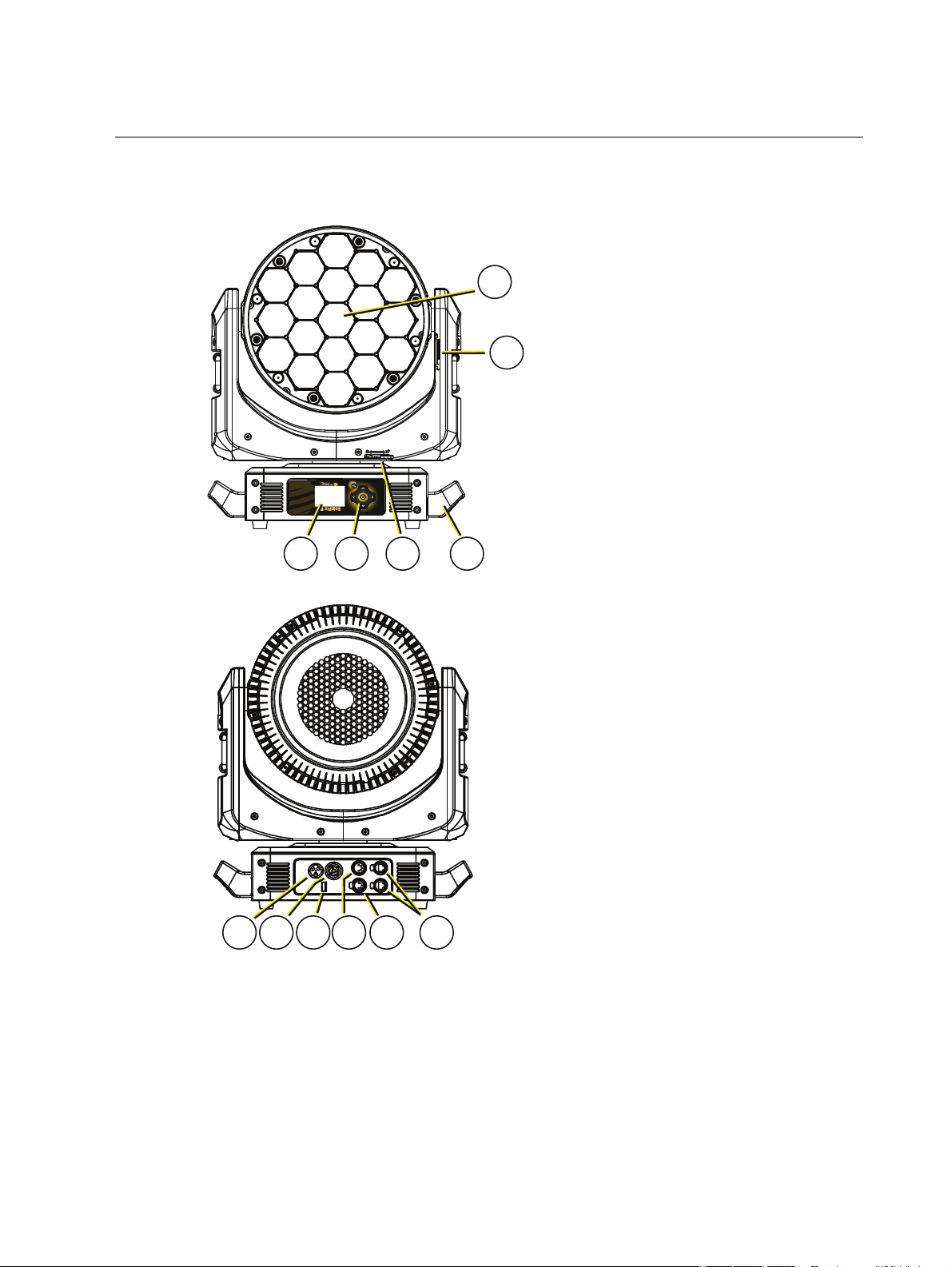
Fixture Overview
2
3
4
5
6
1
8 9
10
11
12
7
For technica l specifications of the SolaPix 19 fixture, see the technical data sheet:
https://www.highend.com/documentation/SolaPix19/SolaPix19-Datasheet.pdf
1: Lens
2: Tilt lock
3: Display
4: Navigation controls
5: Pan lock
6: Handle
7: Power In
8: Power Out
9: USB
10: DMX Thru
11: DMXIn
12: Ethernet ports (x2)
Fix ture Over view 5
Page 10

Modular Control
•
•
•
•
•
•
The SolaPix 19 fixture has three segments of control (or modules) that essentially give you three
fixtures in one, letting you customize each fixture based on your control needs.
The Base module is the master. The settings in this module control the basic functions of
the fixture, which include pan, tilt, zoom, and the control settings for the fixture.
The Macro (Flex) module lets you build and customize animation effects based on a library
of animations.
The Pixel module gives you individual control of each pixel.
The Base module is always a ctive. The Ma cro (Flex) and Pixel modules can be disabled, or they
can be set to Compound or Independe nt modes.
In Compound mode, a module automa tically addresses itself to the sa me source as the Base
module and follows immediately after the address of the Base module.
In Indepe ndent mode, you address a module individua lly to any source (DMX or Ethernet),
Addre ss, or Universe that your control setup requires.
Compounding the modules enables several different options:
Base + Flex (default)
Base + Pixel
Base + Flex + Pixel
Se e
Configure the Fixture on page17
Because the modules all control the same light sources, you ca n set the priority of control using
the Module Priority function (channel 11 in the Ba se module).
for information about configuring the modules.
Se e the DMX map on the High End Systems, Inc. website for details.
https://www.highend.com/documentation/SolaPix19/SolaPix19-protocol.pdf
6 SolaPix 19 User Man ual
Page 11
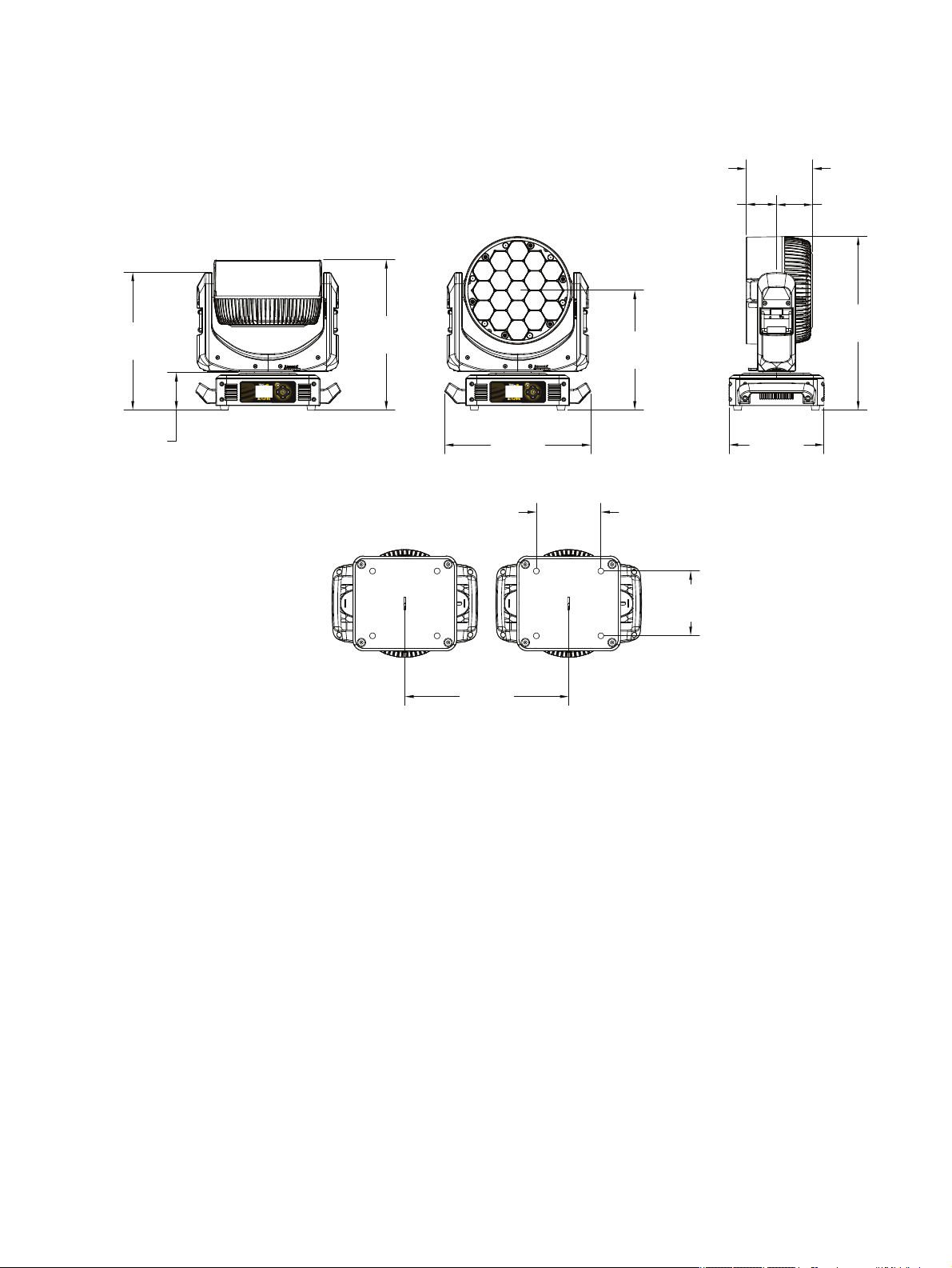
Dimensions
16.5 in
[418 mm]
4.1 in
[104 mm]
15.1 in
[383 mm]
13.1 in
[333 mm]
16.0 in
[407 mm]
19.0 in
[483 mm]
10.4 in
[265 mm]
7.3 in
[186 mm]
3.3 in
[85 mm]
4.0 in
[101 mm]
7.1 in
[180 mm]
7.1 in
[180 mm]
18.0 in
[457 mm]
Dimensions shown are listed as inches [millimeters].
Fix ture Over view 7
Page 12

Safety Considerations
•
•
•
•
•
•
•
•
•
•
•
•
•
•
•
In order to ensure safe operation, follow the safety instructions a nd warning notes in this user
manual and any instructions from the manufacturer representative .
The SolaPix 19 fixture is intended for professional use only. Not for residential use. Read
the entire manual be fore using this equipment.
Conta ct your High End Systems dealer or High End Systems technical support before
performing any service in order to maintain warranty coverage.
WARNING: For your safety, read the following warnings and notice s
before use :
This equipment i s designed for operation by qua lified pe rsonnel only.
Di sconnect the unit from power a nd DMX and data before servicing.
Replace fuses with the spe cified type and rating only.
Mak e sure that the ava ilable v olta ge is within the sta ted range. See
Powe r on page12
NE M A Type 1 enclosure, indoor use, dry locations only. Do not use
outdoors. This fixture is i ntended for use where humidity doe s not
exceed 90% (non-condensi ng).
Do not use this fixture with a da maged powe r le ad ( cord set) . If the
le a d is damaged, it must be replaced by a qua lifie d technician with an
equival ent type be fore use. Contact your loca l authorized de aler for
spa re powe r le a ds.
Do not use this fixture if the lens is damage d. Dama ged lenses must be
replace d before use . Contact your local authorize d dealer for a
replace ment.
When the fixture has be e n stored or tra nsported in cold te mperatures,
allow it to warm to room te mperature for a minimum of one hour
before applying power. Applying power to a cold fixture may cause
dama ge to the fixture and void the ma nufacturer warranty.
This is a Class 1 device and must be grounded. Follow na ti onal a nd
local codes.
Do not proje ct the beam onto combustible substa nces.
Ke ep fixture he ad a t le a st 0.1 m (0.33 ft) awa y from a ny fla mma ble
ma te ria ls.
Minimum distance to lighted obje cts:1 m (3.28 ft).
When y ou power on the fixture, you may notice smok e or odor. This is
normal and should decrease gra dually. I f smoke or odor persists,
disconne ct the fixture from power and contact your High E nd Systems
dealer or High End Systems te chnica l support.
.
CAUTION:
Hot Surfaces. Allow the fixture to cool completely before
handling and serv icing.
8 SolaPix 19 User Man ual
Page 13

CAUTION:
•
•
•
•
•
•
•
•
•
•
•
Damages caused by the disregard of this user manual are not
subject to warranty. High End Systems, Inc. and its authorized dealers will not
accept liability for any resulting defects or problems.
General Operation and Use Guidelines
This fixture is only allowed to be operated with the maximum alternating current that is
stated in the te chnical spe cifications label provided on the fixture.
Lighting effects are not designed for perma nent operation. Consistent ope ration bre aks
may ensure that the fixture will serve you for a long time without defects.
Do not shake the fixture. Avoid brute force when installing or operating the fixture.
When choosing the installation location, make sure that the fixture is not exposed to
extreme heat, moisture, or dust.
If using the supplied Ome ga brackets with quick-locking thumb screws for fixture hanging,
ensure that the thumb screws have engaged a complete 90-degree positive latch.
Operate the fixture only after having familiarized yourself with its functions. Do not permit
other persons who are not qualified and familiar with its functions to operate the fixture .
Please use the original packaging if the fixture is to be transported. ETC and High End
Systems, Inc. will not be responsible for the fixture if packaging other than manufacturer
provided packa ging is used.
Do not modify the fixture. Any modifications will void the warranty.
This manual describes the proper installation and operation of this fixture. Using this
fixture in any way other than the intende d use may cause damage and may void the
warranty.
Misuse of this fixture or using it in a way different from the methods described in this
manual may lead to personal injury a nd/or equipment failure.
The light source of this fixture is not replaceable. When the light source reaches its end of
life, replace the fixture.
Safety Considerations 9
Page 14

Install the Fixture
•
•
•
•
•
•
•
•
•
•
WARNING:
The installation location must support a minimum point loa d of 1 0
times the we ight of the fixture.
The installation must always be se cured with a secondary safe ty
attachme nt. An appropriate safety ca bl e is supplied.
Sa fety cable atta chment must be ra ted by a sa fety factor of 10.
Use of third party clamps are permitted, but they should comply with,
and be approve d by, the Authority Havi ng Jurisdiction (AHJ) .
A supportive and sta ble surfa ce must be used when the fixture s are
placed on the feet.
The operating tempe ra ture ra nge for thi s fixture is -10°C–45°C (14°F–
113°F) . Do not operate the fixture outside of this range .
Ne ver stand directly below the insta lled fixture when mounting,
removing, or se rv icing the fixture.
Al l sa fe ty a nd technica l aspe cts of fixture installa tion must be
approve d by a qualified pe rsonnel before operation.
The installation must be re gularly inspecte d by qua lified pe rsonnel.
Overhead rigging must be performed by qualified pe rsonnel.
CAUTION:
Follow all local codes and recommended practices by the
Authority Having Jurisdiction. The installation must only be carried out by
qualified personnel.
You can install the fixture in any of the orientations shown below.
10 SolaPix 19 User Man ual
Page 15

1
2
53
1. Assemble the clamp (provided by others) to the Omega bracket and se cure toge ther using
appropriately sized hardware ( not provided).
2. Align the asse mbled Omega bra cket and quick-lock fasteners into the respective holes on
the bottom of the fixture upper enclosure.
3. Tighten each of the quick-lock fasteners fully, turning clockwise. You will hear and feel a
click when the fastener is fully se cured.
4. Repeat steps 1 through 3 for the se cond clamp and brack et.
5. Attach the provided safety cable through the attachment point on the bottom of the
fixture upper enclosure and secure to the trussing system or other safe installation point.
Follow local codes and recommende d safety standards for securing the fixture to the
installation location.
6. Attach the fixture to the installation location using the installed clamps, using the clamp
manufacturer's instructions for a secure fit. When using the Omega clamp, close the
safety and fully tighten the clamp wing nut until secure.
7. Inspect the installation prior to lifting the fixture overhe ad.
Inst all the Fixture 11
Page 16

Power
Input and Power Factor
VAC Amps Hz Watts VA PF
100 10.0 50 996 1001 0.99
120 8.1 60 930 965 0.99
200 4.7 50 910 934 0.97
208 4.5 60 928 930 0.97
220 4.3 50 907 938 0.96
240 3.9 60 896 928 0.96
CAUTION:
breaker to trip. Ensure that the circuit can handle the fixture's maximum
potential draw before you connect it.
Using this fixture below 100 V on a 15 A breaker may cause the
Connector Specification
A fixture powe r cord with powerCON TRUE1 input to bare end is provided. Install a suitable
conne ctor to meet the installation requirements. See the following wire color code chart:
Wire Color Code (EU) Wire Color Code (US S tandard) Connection type Terminal
Green/Yellow Green Ea rth/Ground
Blue White Neutral N
Brown Black Line (Live) L
WARNING: RISKOFEL ECT RICSHOCK! The powerCON T RUE 1 is a
connector system consisting of the cable conne ctor and the chassis
rece ptacle. A cable connector i nserted the incorre ct wa y could, in some
circumstances, le ad to conta ct be tween liv e wire s and the grounding conta ct
in the plug socket resulting in e quipme nt ma lfunction and/or personal
injury.
Che ck the condition of your powe rCON TRUE1 connector system ( cable
connector a nd chassis re cepta cle ) for cle ar signs of we ar a nd te ar.
Refere nce the Ne utrik Safety Notice powerCON TRUE1 for more safety
information.
12 SolaPix 19 User Man ual
Page 17

DMX Control
DMX-512
(Belden 9729 or equivalent)
terminate DMX
with a 120 Ohm
resistor
DMX-512
control
source
The SolaPix 19 fixture operates on standard DMX-512 control bus, controlled by a DMX console.
The fixture requires 111 channels of DMX-512 in standard mode.
Attach the fixture to the control bus using a two-core, shielded cable with a 5-pin XLR connector
(Be lden 9729 is preferred).
Two XLR termination receptacles are available: one for connection of DMXInput, and one for
DMXThru (used when daisy-chaining to additional fixtures on the DMX control bus).
DMX Connector Pinout
For DMXInput, the DMX cable must have a ma le XLR connector on one end of the cable that
conne cts to the fixture. When daisy-chaining DMX to the next device, prepare a DMX cable with
a female XLR connector on one end and a male XLR connector on the other end. Terminate the
cable ends as indicated in the pinout image below.
Connect DMXCables to Fixture
The following instructions are guidelines for connecting DMX to your fixture. Your installation
may vary.
1. Conne ct the male XLR connector of a DMX data cable to the DMXThru connector on the
DMX control source.
2. Conne ct the female XLR connector of the DMX data cable to the DMX In connector of the
first fixture on the DMX control run.
3. Continue linking the remaining fixtures by connecting a cable from the DMXThru
conne ctor of a fixture to the DMXIn conne ctor of the next fixture on the control run.
Note:
when installed in a daisy-chain fashion.
A maximum of 32 DMX device s may be connected in any one DMX data run
DMX Cont rol 13
Page 18

Terminate DMX
Use a DMX terminator or install a resistor on the last fixture of the DMXcontrol run to prevent
corruption (data reflection) of the digital control signal by ele ctrical noise.
A DMXterminator is an XLR plug with a 120 Ω resistor conne cted between pins 2 and 3 that can
be installed into the DMX output receptacle of the last fixture in the DMX control run. This plug
is ava ilable and sold separately. Contact your local High End dealer for ordering information
(visit highend.com/about/contact-us to locate a High End deale r).
Set the DMX Start Address
Give each fixture a unique DMX starting address so that the correct fixture re sponds to the
control signals. This DMX start address is the cha nnel number from which the fixture starts to
“listen” to the digital control informa tion sent out from the control source.
Modify the fixture DMX start address on the user inte rface, located on the upper enclosure. See
Addre ss on page18
Example: The SolaPix 19 requires up to 111 channe ls of control depending on the
configuration of the modules. The Base module uses 20 channels. When the Macro
(Flex) module is set to Compound mode, an additional 15 channels are added. If the
Pixel module is also set to Compound mode , then an additional 76 channels are added,
making 111 cha nnels total.
If you are using the Base and Pixel modules (the Pixel module is set to Compound mode
and the Macro (Flex) module is disabled) the total channel usa ge is 96 channels.
.
DMX Channels
The most current DMX Map data for the SolaPix 19 can be found on the High End Systems, Inc.
website:
https://www.highend.com/documentation/SolaPix19/SolaPix19-protocol.pdf
14 SolaPix 19 User Man ual
Page 19

Ethernet Control
Ethernet
control
source
Cat5e (or better) Cat5e (or better) Cat5e (or better)
The SolaPix 19 fixture includes two Ethernet ports that allow sending and receiving of control
signals using the Art-Net protocol or sACN.
Use a Cat5e (or better) cable and terminate to RJ45 connectors following the TIA/EIA 568B
wiring standard.
Connect EthernetCables to a Fixture
The following instructions are guidelines for connecting Ethernet to your fixture. Your
installation may vary.
1. Conne ct a cable from the Ethernet control source to one of the Ethernet ports on the first
fixture in the E thernet control run.
2. Conne ct the first fixture to a second fixture by connecting a cable from the second
Ethernet port on the first fixture to one of the Ethernet ports on the second fixture.
3. Continue linking the remaining fixtures by connecting a cable from Ethernet port to
Ethernet port on the fixtures on the control run.
Note:
The Cat5e cable distance should not exceed 100 m, and you should not
conne ct more than 20 fixtures in one Ethernet control run when the fixtures are linked
together.
Ethernet Cont rol 15
Page 20

Set the DMX Start Address
Give each fixture a unique DMX starting address so that the correct fixture re sponds to the
control signals. This DMX start address is the cha nnel number from which the fixture starts to
“listen” to the digital control informa tion sent out from the control source.
Modify the fixture DMX start address on the user inte rface, located on the upper enclosure. See
Addre ss on page18
.
Example: The SolaPix 19 requires up to 111 channe ls of control depending on the
configuration of the modules. The Base module uses 20 channels. When the Macro
(Flex) module is set to Compound mode, an additional 15 channels are added. If the
Pixel module is also set to Compound mode , then an additional 76 channels are added,
making 111 cha nnels total.
If you are using the Base and Pixel modules (the Pixel module is set to Compound mode
and the Macro (Flex) module is disabled) the total channel usa ge is 96 channels.
Set the Control Source and Universe
For Ethernet control, you must configure the control source (Art-Net or sACN) and set a universe
(000-255) for each fixture. S ee
Addre ss on page18
for details.
16 SolaPix 19 User Man ual
Page 21

Configure the Fixture
Mode
Esc.
Mode
Esc.
Mode
Esc.
You can configure SolaPix 19 fixtures through the onboard user interface.
Navigate the User Interface
1.
Press the [MODE /ESC] button (
battery when the fixture has no power.)
2. Browse the menu by pressing the up, down, left, or right navigation buttons.
3.
Press the [Enter] button ( ) to select a menu item.
4. Modify the selection by pressing the up, down, left, or right navigation buttons according
to the selection.
5.
Press the [Enter] button ( ) to confirm a modified se lection.
6.
To exit the menu, press the [MODE/ ESC] (
) to access the main menu. (The display is powered by
)button.
Note:
If you press the [Enter] button to confirm a se lection and push no othe r buttons,
the user interface returns to the default displa y a fter 15 seconds.
Configur e the Fixt ur e 17
Page 22

Set Fixture Parameters
•
•
•
This section provides instructions to configure and set up the S olaPix 19. See
Interface on the previous page
for information about the na vigation buttons.
Navigate the User
Provide power to the fixture before configuring it. If you do not provide power, the fixture will
use battery power to power the user interfa ce.
Address
Na vigate:Main Me nu → Address
The Address menu provides access to configure the thre e modules: Base, Macro (Fle x), and
Pixel. You can configure each module individually, or you can compound some or all of the
modules. For information about the modules, see
Na vigate:Main Me nu → Address → Base Module
Base module configuration is manda tory. You must configure this module for each fixture.
Se ttings Value Description
DMX
Source
Art-Net
Se lect the control source for the Base module.
sACN
Addre ss 001-xxx Set the DMX address for the Ba se module.
Universe 000-255
When using Art-Net or sACN control source, set the
universe.
Modular Control on page6
.
18 SolaPix 19 User Man ual
Page 23

Na vigate:Main Me nu → Address → Macro Module
•
•
•
•
•
•
•
•
•
The Macro (Flex) module is an optional feature. S elect Disable in the Mode menu to turn off the
module.
Se ttings Value Description
Se lect how the Macro (Flex) module is implemented:
Compound - the module inherits its settings from
Mode
Independent
Compound
Disable
the Ba se module. See the
Universe
settings for details.
Independent - the addressing and control of the
module are independent of the other modules.
Source,Addre ss
, and
Disable - the module is off.
The default mode is Compound.
Se lect the control source for the Macro (Flex) module.
Source
DMX
Art-Net
sACN
Note: This option is only available whe n the Mode
selection is set to Indepe ndent. W hen you set the
module to Compound mode, the Source is inherited
from the Base module.
Se t the DMX address for the Macro (Flex) module.
Note: This option is only available whe n the Mode
Addre ss 001-xxx
selection is set to Indepe ndent. W hen you set the
module to Compound mode, the Address is inherite d
from the Base module Address (Base module
Addre ss+20).
When using Art-Net or sACN control source, set the
universe.
Universe 000-255
Note: This option is only available whe n the Mode
selection is set to Indepe ndent. W hen you set the
module to Compound mode, the Universe setting is
inherited from the Base module.
Configur e the Fixt ur e 19
Page 24

Na vigate:Main Me nu → Address → Pixel Module
•
•
•
•
•
•
•
•
•
The Pixel module is an optional feature. Select Disable in the Mode menu to turn off the
module.
Se ttings Value Description
Se lect how the Pixel module is implemented:
Compound - the module inherits its settings from
Mode
Independent
Compound
Disable
one of the other modules. See the
and
Universe
settings for details.
Independent - the addressing and control of the
module are independent of the other modules.
Source,Addre ss
Disable - the module is off.
The default mode is Disable.
Se lect the control source for the Pixel module.
,
DMX
Source
Art-Net
sACN
Addre ss 001-xxx
Universe 000-255
Note: This option is only available whe n the Mode
selection is set to Indepe ndent. W hen you set the
module to Compound mode, the Source is inherited
from the Macro (Flex) module (or the Base module if
the Macro (Flex) module is disabled).
Se t the DMX address for the Pixel module.
Note: This option is only available whe n the Mode
selection is set to Indepe ndent. W hen you set the
module to Compound mode, the Address is inherite d
from the Macro (Flex) module Address (Macro (Flex)
module Address+15). If the Macro (Flex) module is
disabled, then the Address is inherite d from the Base
module Address (Base module Address+20).
When using Art-Net or sACN control source, set the
universe.
Note: This option is only available whe n the Mode
selection is set to Indepe ndent. W hen you set the
module to Compound mode, the Universe setting is
inherited from the Base module.
20 SolaPix 19 User Man ual
Page 25

Exampl e Use Cases
•
•
-
-
•
•
•
-
-
-
-
•
Default Use Case
The system has a small number of fixtures and limited universes of DMX, so numerous cha nnels
of DMX cannot be dedicated to each individual fixture.
Example:
For each fixture:
Configure the Base module with DMX source and a unique address.
Use the default settings for the Macro (Flex) and Pixel modules:
Macro (Flex) module set to Compound mode
Pixel module set to Disable mode
The result: All fixture s have 35 channels of control for Base module functions and
Macro (Flex) module animations. The re commended console library is Base + Flex.
Many U niverses of DMX Controlled by a Console
The system has many universes of DMX available, so 111 channels of DMX can be dedicated to
ea ch individual fixture.
Example:
For each fixture:
Configure the Base module with DMX source and a unique address.
Se t both the Macro (Fle x) and Pixel modules to Compound mode.
The result: All fixture s have 111 channels of control for Base module functions,
animations, and pixels. The recommended console library is Base + Flex + Pixel.
Limited Universes of DMX with Individual Control
The system does not have enough DMXto dedicate 35 channe ls of DMX to ea ch fixture, but
individual control of each fixture is necessary.
Example:
For each fixture:
Configure the Base module with DMX source and a unique address, for example:
Fixture 1 = a ddress 1
Fixture 2 = a ddress 21
Fixture 3 = a ddress 41
.
.
.
Fixture 24 = address 461
Configure the Macro (Flex) module with the Indepe ndent mode and an address
that is common for all fixtures (addre ss 481 in this example).
The result: You can control each fixture individua lly and you can access the Flex effects
(although all fixtures will pe rform the same animation). The recommended console
libraries are Base for each unique fixture and a single instance of Flex for the
Flex/Macro control.
Configur e the Fixt ur e 21
Page 26

Separate Console Control and Video Server Control
•
•
•
•ON•
•ON•
The system contains a vide o control source in addition to a DMX console.
Example:
For each fixture:
Configure the Base module with DMX source and a unique address.
Se t the Macro (Flex) module to Compound mode .
Se t the Pixel module to Independent mode, set the sACN or Art-Net source, and
assign a unique DMX address and universe.
The result: All fixture s have control for the 35 channels of Base module functions
and animations via DMX, and 76 channels of control for the P ixel module via
Ethernet from a video server.
Info Menu
Set the Time Information
Na vigate:Main Me nu → Info → Time Info
Pa rameter Value Description
Running time of the fixture from the last time that
Curre nt Time XXXX (Hours)
the fixture was powered on, shown in hours (h). The
counter resets after the fixture is turned off.
Ttl Life Hrs XXXX (Hours) Total running time of the device, shown in hours (h).
Last Run Hrs XXXX (Hours)
LEDHours XXXX(Hours)
Running time of the fixture from the last time that
the run time value was reset, shown in hours (h).
Total running time of the fixture LEDs, shown in
hours (h).
You must enter the Time r PIN in order to access the
Timer PIN Timer PIN XXX
Clr Last Run menu ite m. The default Time r PIN is
038.
This password-protected menu item resets the La st
Run Hrs value. You must enter the Timer PIN to
Clr Last Run
OFF
access this me nu item.
Se lect ON to clear the value for the Last Run Hrs
parameter for the fixture.
You must enter the LED Time PIN in order to access
the Clear LED Time menu item. The de fault LED
Time PIN is 038.
LEDTime PIN
LED Time PIN
XXX
This password-protected menu item resets the LE D
Hours va lue. You must enter the LED Time PIN to
Clear LE D T ime
OFF
access this me nu item.
Se lect ONto clear the value for the LED Hours
parameter.
22 SolaPix 19 User Man ual
Page 27

View Fixture Errors
Na vigate:Main Me nu → Info → Error Info
Displa ys any curre nt fixture errors. See
Error Codes on page30
for information about the errors.
View DMX Values for Channels
Na vigate:Main Me nu → Info → DMX Value
View the DMX value of each of the fixture 's cha nnels (para me ters of the fixture). Scroll to the
parameter that you want to view (Pan, Tilt, e tc.) and view the value. The DMX value that you
view is the DMX value tha t displays on the main window of the UI until you select a different
DMX value to view.
View Fixture Head Temperature
Na vigate:Main Me nu → Info → Head Temp
Displa ys the current fixture tempe rature as read from the fixture head (near the CMYfilter).
View Power Temperature
Na vigate:Main Me nu → Info → Power Temp
Displa ys the current temperature as read from the power supply in the fixture base, which can
help you to determine if the power supply is overheating.
View Fan Speeds
Na vigate:Main Me nu → Info → Fan Speed
Displa ys the speeds of the fixture 's fans (in RPM).
View Ethernet IP Address
Na vigate:Main Me nu → Info → Ethernet IP
Displa ys the Ethernet IP address for the fixture. You can modify this value in the Set menu. See
Access Service Settings on page25
.
View Software Version
Na vigate:Main Me nu → Info → Software Ver
Displa ys the software version for the fixture.
Configur e the Fixt ur e 23
Page 28

Set Menu
•ON•
•ON•
•
•
•ON•
•
•
•
•
•
•
•
•
•
•
•
•
•
•
Set the Status Options
Na vigate:Main Me nu → Set → Status
Pa rameter Value Description
Pa n Reverse
Tilt Reve rse
Pa n Degree
Encoders
Hibernation
Refresh Rate
OFF
OFF
630
540
OFF
OFF
1–99 minute s
2.4 kHz
16 kHz
Reverse the pan movement of the fixture . The
default value is OFF.
Reverse the tilt movement of the fixture. The default
value is OFF.
Change the pan rotation of the fixture from the
default setting of 540 degrees to 630 degrees.
Turn on or off the encode r feedback for pan and tilt
movement. You may want to turn off encoders when
working on a fixture so tha t you can move pa n and
tilt without the fixture automatically moving back to
position.
Hibernation mode forces the LEDs and stepper
motors to power off when the fixture loses DMX
control signal for a set period of time. The de fault
time setting is 15 minutes.
Se t the refresh rate of the fixture. T he higher 16 kHz
setting crea tes a beam with less "strobing" on
camera, but it is noisier than the 2.4 kHz setting.
Se t the order in which pan and tilt homing is
performed.
Standard: the pan and tilt home procedures run
P/T Home Mode
Standard
Tilt First
Pa n First
simultaneously.
Tilt First: the tilt home procedure runs to
completion, then the pan home procedure
begins.
Pa n First: the pan home procedure runs to
completion, then the tilt home procedure begins.
Se t the modules to which the Dimmer DMX channel
is applied.
Master Base
Dim Control
Intensity
Independent
Base Intensity
Master Base Intensity: the Dimmer DMX channel
is applied to the Base, Macro (Flex), and Pixel
modules.
Independent Base Intensity: the Dimmer DMX
channel is applied only to the Base module .
24 SolaPix 19 User Man ual
Page 29

Access Service Settings
•ON•
Na vigate:Main Me nu → Set → Service Setting
Pa rameter Value Description
You must enter the Service PIN in order to access
Se rvice PIN Se rvice PIN XXX
RDM UID
RDM UDIs for each
module
the other Service Setting parameters. The default
Se rvice PIN is 050.
This password-protected menu item lets you
modify the RDM UID. You must enter the Service
PIN to access this menu ite m.
Ea ch module has a unique RDM UDI tha t consists
of the manufacturer ID and a ra ndomly generated
number.
Note:Remote Device Management (RDM)
requires that all RDM devices have a unique
identifier (UID). Modifying this setting can break
the RDM capability of this fixture.
Duplicate RDM UIDs on the same DMX control run
will result in a data collision, causing a
communication failure. Ensure that all fixture s
have a unique RDM UID if RDM functiona lity is to
be used.
Ethernet IP XXX.XXX.XXX. XXX
Ethernet
MaskIP
Clr Err Info
XXX.XXX.XXX.XXX
OFF
If DMX splitters are use d and RDM control is to be
used, the se splitters must support RDM.
This password-protected menu item lets you
modify the IP address. You must enter the Service
PIN to access this menu ite m.
The default IP address is 002.142.058.034.
This password-protected menu item lets you
modify the IP subnet ma sk. You must enter the
Se rvice PIN to access this menu item.
The default IP subnet mask is 255.000.000.000.
This password-protected menu item lets you clear
error messages after you have fixed the errors.
You must enter the Service PIN to acce ss this
menu item.
Se t this para meter to ON in order to clear the error
messages. T he default setting is OFF.
Configur e the Fixt ur e 25
Page 30

Set the Fans Mode
•
•
•ON•
•ON•
•
•
•
•
•
Na vigate:Main Me nu → Set → Fans Mode Setting
Se lect the fan mode for the fixture:
Standard
Studio (reduces fan noise, but decrea ses fixture output by ~20%)
Set Display Settings
Na vigate:Main Me nu → Set → Disp. Setting
Pa rameter Value Description
Enter the amount of time the fixture waits afte r the
Shutoff Time 02–60 minutes
Flip Display
Key Lock
OFF
OFF
last user interface button press until the display goes
to sle ep. The default va lue is 5 minutes.
Flip the display 180° when the fixture is mounted
vertically. The default value is OFF.
Shortcut: With the main UI window displayed, press
[>] to flip the displa y 180°. Press [<] to flip it back to
its original orientation.
Lock the user interface. The default value is OFF.
To unlock the use r interface buttons, press and hold
the [MODE/ESC] button for three seconds.
Set the Temperature Scale
Na vigate:Main Me nu → Set → Temp. C/F
Se lect the temperature scale for the fixture:
Celsius (default value)
Fahrenheit
Update Fixture Firmware Using the USB Port
Na vigate:Main Me nu → Set → USB Update
Fixture firmware updates are a vailable on the High End Syste ms, Inc. website at highend.com.
1. Sa ve the firmware update file to a USB drive.
2. Insert the USBdrive in the fixture base (see
location).
3. On the Main M enu, select Set → US B Update. The fixture re ads the USBdrive and
displays a list of any firmware update file s on the USB drive.
4. Se lect the appropriate file and then pre ss the [Enter] button.
5. The software prompts you to confirm the update with the message "Update fixture?" Use
the na vigation buttons to select "Yes," and then press the [Enter] button.
The firmware upda te begins. A progress monitor shows you the progress of the
update.
The fixture restarts when the update is complete, and the fixture performs a data
check to verify the update.
The firmware upda te is complete when the display returns to its default state.
6. Remove the USBdrive from the fixture.
Fixture O verview on page5
for the USB port
26 SolaPix 19 User Man ual
Page 31

Reset Fixture to Factory Default Settings
Na vigate:Main Me nu → Set → Reset Default
Se lect ON to reset the fixture to the factory default settings.
Test Menu
Reset (Home) the Mechanical Positions on the Fixture
Na vigate:Main Me nu → Test → Home
Reset ("home") all features on the fixture, including, pan, tilt, colors, gobos, etc.
Test the Fixture
Na vigate:Main Me nu → Test → Self Test
Run a self-test program on the fixture. When you run the test, the display indicates "Running"
and the fixture automatically runs a se lf-test procedure, testing ea ch of the functions. Press
[MODE/ESC] button to end the self-test and return the displa y to the previous menu.
Test an Indi vidual Channel
Na vigate:Main Me nu → Test → Test Channel
Run a self-test program on individual cha nnels. The default value is Control. Select a different
channel to run a self-test on that channe l.
Manually Set an I ndividual Channel
Na vigate:Main Me nu → Test → Manua l Ctrl.
Se lect an individual channel on the fixture and manually set the channel value . While in Manual
Control mode, all effects a re canceled, the shutter opens, and the dimmer intensity is set to
100%.
Re-Calibrate an Individual Feature
Na vigate:Main Me nu → Test → Calibration
Please contact technical support at High End Systems, Inc. before using this parameter. See
Conta cting High End Systems on pa ge1
You must enter the Calibration PIN in order to access the Calibra tion menu items. The default
Calibration PIN is 050.
Once you have accessed the Calibration menu, select an individua l fe ature on the fixture and
manually calibra te it to a new "home" setting.
.
Preset Menu
Set the Playback Settings
Na vigate:Main Me nu → Preset → Play Back
Playback settings allow you to run an Auto Program as a Master fixture or in stand-alone mode,
or to receive playback information from a different Master fixture.
Prese t programming require s one fixture to act as the Master. All other SolaPix 19 fixtures that
are connected to the designate d Master fixture can the n receive Auto Programs from the Master
fixture.
Configur e the Fixt ur e 27
Page 32

Example: You edit groups of scenes into Programs 1–10 on the Master fixture .
•
•
•
- Program 2 is assigned to Part 1
- Program 4 is assigned to Part 2
- Program 6 is assigned to Part 3
* Fixtures assigned as Slave 1 will play back Part 1
* Fixtures assigned as Slave 2 will play back Part 2
* Fixtures assigned as Slave 3 will play back Part 3
Se lect the appropriate playback setting:
DMX Control: Return the fixture to DMXcontrol from another playback mode.
Se t To Slave:Fixture will play back the Auto Program that is defined on the Master fixture .
Auto Program:Fixture runs an Auto Program either in stand-alone mode or as a Master
fixture. Use the S elect Prog parameter to select the program (see
below
).
Se lect an Auto Program
Select an Auto Program
Na vigate:Main Me nu → Preset → Select Prog.
Se lect the Auto Program that the fixture will run either in stand-alone mode or as a Master
fixture.
Program Range Default Value
Prog. Part 1 Program 1–Program 10 Program 1
Prog. Part 2 Program 1–Program 10 Program 2
Prog. Part 3 Program 1–Program 10 Program 3
Edit an Auto Program
Na vigate:Main Me nu → Preset → Edit Program
Create the Auto Program that the fixture will run either in stand-alone mode or as a Master
fixture (see
Navigate to the Auto Program that you want to edit (Program 1, Program 2, etc.), and then set
the scene (SC001, SC002, etc.)for each step (Step 01, Step 02, etc.) in the Auto Program. You
can set a maximum of 64 steps. T he SolaPix 19 fixture provides 250 pre-programmed scenes, or
you can customize scenes using the Edit Scenes paramete r (see
a Sce ne on the facing page
Se lect an Auto Program above
).
).
Edit a Scene or Capture (Record)
28 SolaPix 19 User Man ual
Page 33

Edit a Scene or Capture (Record) a Scene
Na vigate:Main Me nu → Preset → Edit Scenes
The SolaPix 19 fixture provides 250 pre-programmed scenes that you can use or edit to build an
Auto Program. Each scene is a snapshot of a set of fixture parameters (for example, color, beam
quality and pattern, intensity, focus, etc.) that you can assign to a ste p in an Auto Progra m.
Se lect the scene (Scene 001, Scene 002, etc.) that you want to edit, and then set the
parameters for the scene or capture the parameters for the scene from the current DMX input.
In addition to standard SolaP ix 19 features (pan, tilt, etc.), scene parameters include the
following options.
Pa rameter Value Description
Fade Time 0–255 se conds
Scene Time
Input By Out
0.2–99.9
seconds
Enter the crossfade time a pplied to parameters when
the scene plays.
Enter how long the scene will play before the next
scene plays. The de fault value is 0.3 seconds.
Capture the parameter values for the scene from the
current DMX input.
Capture (Record) Multiple Scenes
Na vigate:Main Me nu → Preset → Scenes Input
You can capture DMXdata and record those parameters as a series of scenes. Select the start
and end scene numbers for the range of scene s that you wa nt to record. The fixture records the
incoming DMXdata into the se lected scenes, with each change in DMX data triggering the next
scene in the range. When all scenes in the ra nge have been recorded, the display re turns to the
main me nu.
Note:
DMX input; it only captures the data. You must edit or play back the scene after
recording is complete to verify the results. W e suggest that you prepare the scenes on a
DMX controller with a zero crossfade for all parameters be tween steps. Remember that
any change of a DMXvalue will automatically advance to the next scene during
capture.
While capturing the DMX data, the S olaPix 19 fixture does not play back the
Configur e the Fixt ur e 29
Page 34

Error Codes
•
•
•
•
•
•
•
•
•
When you apply powe r to the fixture, it runs a ca libration (homing) sequence and displays a ny
errors that it detects.
Example: For example, when the display shows "Error channel: Pan Coarse", it
means there is an error in channel 1. When multiple errors are present they will cycle
on the display twice, and then the fixture will reset (restart). Any errors that remain
after two reset cycles are not correctable by reset alone and will require se rvice. Please
conta ct support if detailed assistance is neede d.
This message displays after the reset of the fixture if any of the following conditions exist:
Pan Coarse
This message displays after the reset of the fixture if any of the following conditions exist:
the yoke’s magnetic-indexing circuit malfunctions (optical or magnetic sensor failure)
the stepper motor is defective or the related IC driver on the main PCB has failed
the Pan movement is not located in the default position after the reset
Tilt Coarse
This message displays after the reset of the fixture if any of the following conditions exist:
the fixture head magnetic-indexing circuit malfunctions (optical or magnetic sensor
failure)
the stepper motor is defective or the related IC driver on the main PCB has failed
the Tilt movement is not located in the default position after the reset
Zoom Wheel
This message displays after the reset of the fixture if any of the following conditions exist:
the magnetic-indexing circuit malfunctions (optical or magnetic sensor failure)
the stepper motor is defective or the related IC driver on the main PCB has failed
the Zoom movement is not loca ted in the default position after the rese t
30 SolaPix 19 User Man ual
Page 35

Cleaning and Maintenance
•
•
•
•
•
CAUTION:
Disconnect the fixture from mains power before starting any
maintenance procedures.
Keep the following in mind during regular service and inspection:
All screws for insta lling the device or parts of the device must be tightly connected and
must not be corroded.
There must not be any deformations to the housing, lenses, rigging, and installation points
(ceiling, suspension, trussing) .
Moving parts must not show any signs of wear and must move smoothly without issue.
The power supply cables must not show any damage, material fatigue, or se diment.
If spare parts are required, order only genuine parts from your local authorized dea ler.
To ensure that the device re ma ins in good work ing condition and does not fail prematurely,
regular maintenance is recommended.
CAUTION:
The backside of each lens in the SolaPix 19 fixture is coated with
a HazeFree lens coating technology (patent pending) that keeps the lens clear
when the fixture is used with theatrical haze. Use of paper toweling or other
abrasive, high-friction wi pes and ammonia-based glass cleaners may
permanently damage the coating.
If the lens coating wears away, contact High End Systems, Inc. Technical
Services for assistance.
1. Clean the lens only whe n necessa ry, and only use a Silky Microfiber Optical Cloth with
purified water or an ammonia-free glass cleaner such as Miller Stevenson MS-260 Glass
Cleaner.
2. Clean the fans regularly to ensure maximum airflow and efficient cooling. This will ensure
that the light source operates in the best possible condition.
Cleaning and Maintenance 31
Page 36

Headqu ar te rs n 2105 Gracy Farms Lane, Austin , TX, 78758 USA n Tel +512 836 2242 n Fax + 512 837 5290
Gl o bal Offi ces n Lo nd on , UK n Ho lzki rchen , DE n Ho ng Kong
Web hig hen d. co m n S upp ort s up po rt .etccon nect. com/H ES
© 2019 El ect ronic Theat re Co nt ro ls, Inc. n Pr oduct i nformat ion and s pecif icati on s su bj ect to ch ange.
ETCi nt ends th is d ocumen t t o be p ro vid ed i n it s ent iret y. n Trad emark and paten t in fo: etccon nect. co m/i p
So l aPi x 19 Us er Manual R ev A R eleased 2019-12
 Loading...