

Page 1

USER MANUAL
Version 1.3 -- Revision A
Page 2

SolaHyBeam 2000 User Manual 2 v1.3
Page 3

Contents
Welcome 5
KEEP THIS MANUAL FOR FUTURE NEEDS 5
Contacting High End Systems ® 6
Patent information 9
FCC Information 10
Terms and Conditions and Warranty Information 11
SAFETY INSTRUCTIONS 12
IMPORTANT SAFETY WARNING 12
GENERAL GUIDELINES 13
FEATURES 14
Photometric data image 16
Fixture Overview 17
DIMENSIONAL DRAWINGS 18
INSTALLATION INSTRUCTIONS 19
RIGGING THE DEVIC E 19
DMX-512 CONTROL CONNECTION 22
DMX-512 CONNECTION WITH DMX TERMI NATOR 22
DEVICE DMX START ADDRESS SELECTION 22
DISPLAY 23
Address 26
Info 26
SET 30
Service PIN 31
Test 32
Preset 33
Example Program 35
DMX Control Protocol 36
ERROR MESSAGES 40
CLEANING AND MAINTENANCE 42
SolaHyBeam 2000 User Manual 3 v1.3
Page 4

SolaHyBeam 2000 User Manual 4 v1.3
Page 5
Welcome
Notice
© High End Systems, 2017, All Rights Reserved
Information and specifications in this document are subject to change without notice. High End Systems
assumes no responsibility or liability for any errors or inaccuracies that may appear in this manual.
Trademarks used in this text: High End Systems, Wholehog, and Lithopatterns, and intellaspot are
registered trademarks. Internal Effects, the High End Systems globe logo and the Hog logo are trademarks
of High End Systems, Inc. Belden is a registered trademark of Belden, Inc.
Other trademarks and trade names may be used in this document to refer to either the entities claiming the
marks and names or their
products. High End Systems disclaims any proprietary interest in trademarks and trade names owned by
others.
KEEP THIS MANUAL FOR FUTURE NEEDS
Thank you for your patronage. You have acquired a powerful and versatile fixture. We are confident that
you will be satisf ie d wit h our excellent products and service. For your own safety, please read this user
manual carefully before installing and operating the device.
SolaHyBeam 2000 User Manual 5 v1.3
Page 6

Contacting High End Systems ®
Sales Department
Customer Service
World Wide Web
http://www.highend.com
High End Systems, Inc.
2105 Gracy Farms Lane
Austin, TX 78758 USA
voice: 512.836.2242
fax: 512.837.5290
Toll Free: 800.890.8989
High End Systems, Inc.
2105 Gracy Farms Lane
Austin, TX 78758 USA
voice:800.890.8989
fax: 512.834.9195
toll free: 800.890.8989
email: support@highend.com
SolaHyBeam 2000 User Manual 6 v1.3
Page 7
DECLARATION OF CONFORMI T Y
SolaHyBeam 2000 User Manual 7 v1.3
Page 8
SolaHyBeam 2000 User Manual 8 v1.3
Page 9

Patent Information
Notice of intellectual property rights
For a listing of current patents go to the web address:
https://www.highend.com/patents
SolaHyBeam 2000 User Manual 9 v1.3
Page 10

FCC Information
This equipment has been tested and found to comply with the limits for a Class A digital device, pursuant to
part 15 of the FCC rules. These limits are designed to provide reasonable protection against harmful
interference when the equipment is operated in a commercial environment. This equipment generates,
uses, and can radiate radio frequency energy and, if not installed and used in accordance with the
instruction manual, may cause harmful interference to radio communications.
Operation of this equipment in a residential area is likely to cause harmful interference, in which case the
user will be required to correct the interference at his own expense.
SolaHyBeam 2000 User Manual 10 v1.3
Page 11

Terms a nd Conditions and Warranty Information
Complete Terms and Conditions and Warranty information can be foun d on the H igh End Sy stems, I nc.
website https://www.highend.com/pub/products/HES-Warranty-Information.pdf
.
SolaHyBeam 2000 User Manual 11 v1.3
Page 12
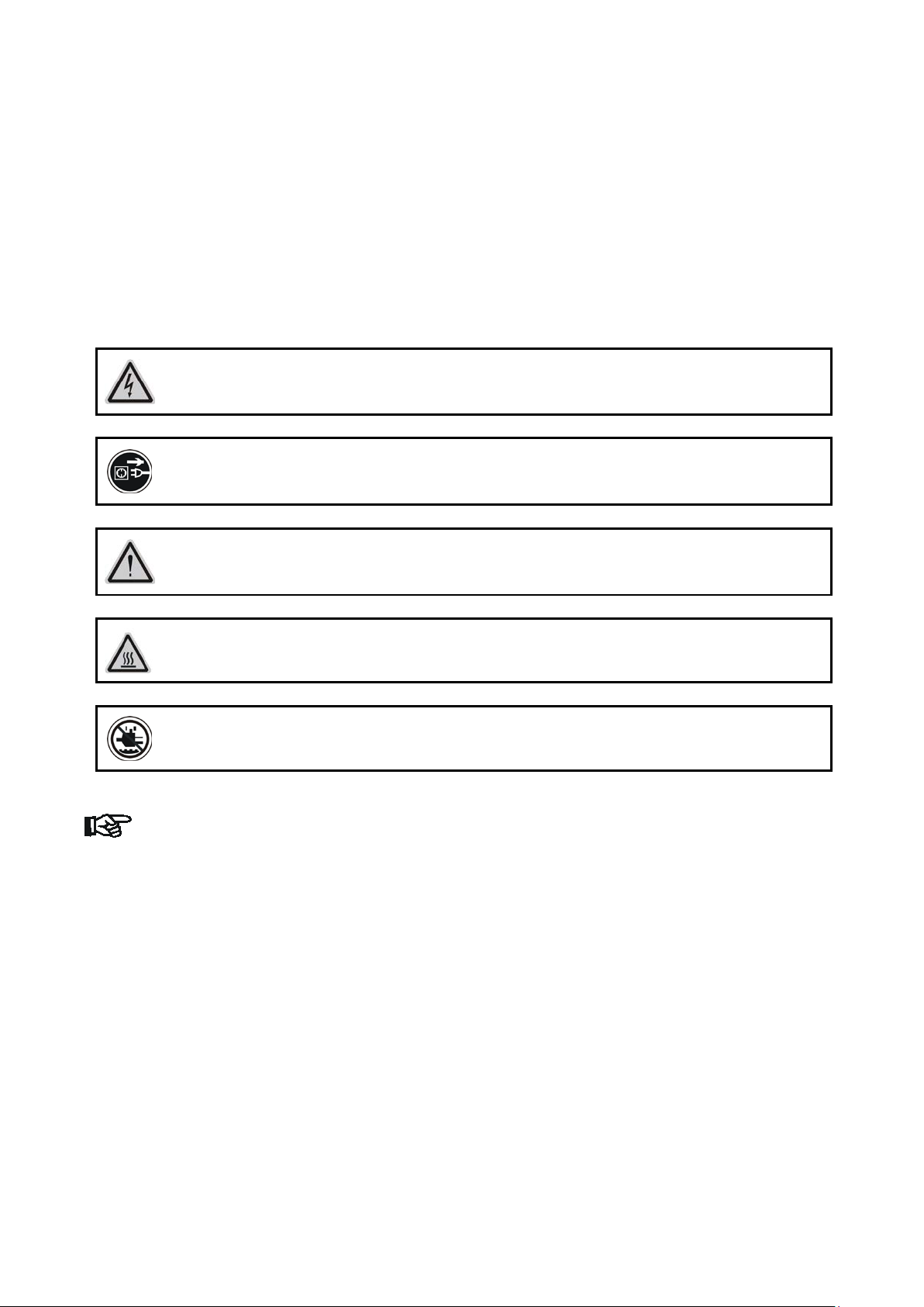
CAUTION!
FIXTURE COVERS
CAUTION!
MAY SUFFER AN EPILEPTIC SHOCK
SAFETY INSTRUCTIONS
IMPORTANT SAFETY WARNI NG
This device has left the factory in perfect condition. In order to maintain this condition and to ensure safe
operation, it is absolutely necessary for the user to follow the safety instructions and warning notes written
in this user manual.
In order to install, operate, and maintain the light ing fix ture saf el y and corr ectly we suggest that the
installation and operation be carried out by qualified technicians and these instructions be carefully
followed.
CAUTION!
HIGH VOLTAGE. RISK OF SEVERE OR FATAL ELECTRIC SHOCK
ALWAYS DISCONNECT MAINS SUPPLY BEFORE REMOVING ANY
NEVER LOOK DIRECTLY INTO THE LIGHT SOUR CE. SENSITIV E PERSONS
CAUTION!
NEVER TOUCH THE DEVICE DURING OPERATION! COVERS MAY BE HOT
CAUTION!
KEEP THIS DEVICE AWAY FROM RAIN AND MOISTURE
Important:
Damage caused by the disregard of this user manual is not subject to warranty. The
dealer and manufacturer will not accept liability for any resulting defects or
problems.
• If the device has b een exposed to tem perature changes due to environm ental conditions, do not
power on immediately. The resulting condensation could damage the device. Leave the device
powered off until it has reached room temperature.
• This device falls under protection-class I. Therefore, it is essential that the device be earthed.
• If either lenses or dis play are damaged (damage may include cracks or gashes in the m aterial)
they must be replaced.
• Electrical connections, such as replacing the power plug, must be performed by a qualified person.
• Make sure that the available voltage is not higher than that which is stated at the end of this
manual.
• Make sure the po wer cord is never c rushed or dam aged by sharp edg es. Should the power cord
suffer, replacement of the cable must be done by an authorized dealer.
• If the external flex ib le power cord of this de vice is damaged, it s ha ll be exclusively replac ed by the
manufacturer or their service agent or a similar qualified person in order to avoid injury.
• When the device is not in use or before perf orming maintenance, alwa ys disconnect the device
from the mains. O nly handle the po wer cord from the plug. N ever pull the plug out of a socket b y
tugging the power cord.
• When powered on for the fir st t ime, som e sm ok e or smell may occur. This is caus ed b y coat ing on
SolaHyBeam 2000 User Manual 12 v1.3
Page 13

metal parts when heated and is normal. If you are concerned, please contact your distributor.
• Do not focus the beam onto flammable surf aces. The minimum distance between the exiting lens
of the device and the illuminated surface must be greater than 1.5 meter.
Please be aware that damage caused by any modifications to the device are not subject to
warranty. Keep away from children and non-professionals.
GENERAL GUIDELINES
• This device is a lighting ef fect for professional use on stages, in discotheques, t heatres, etc., the
device was designed for indoor use only.
• This fixture is onl y allowed to be operated w ithin the m axim um alternating c urrent as stated in t he
technical specifications in section 2 of this manual.
• Handle the device with care, avoid shaking or using force when installing or maintaining the device.
• When choosing the installation location, please make sure that the device is not exposed to
extreme heat, moisture or dust.
• If you use the quick lock cam when rigging the de vice, make sure the quick lock fasteners are
located in the quick lock holes correctly and securely.
• Operate the device only after having familiarized yourself with its functions. Do not permit operation
by persons not qual ified for operating t he device. Mo st damages are the result of unprofes sional
operation.
• Please use the original packaging if the device is to be transported.
• The applicable temperature for the device is between -10°C to 45°C. Do not use the device out s i de
of this temperature range.
For safety reasons, please be aware that all modifications to the device are forbidden.
If this device is operated in any way different to the ones described in this manual, the
product may suffer damage and the warranty becomes void. Furthermore, any other
operation may lead to short-circuits, burns, electric shocks etc.
SolaHyBeam 2000 User Manual 13 v1.3
Page 14

FEATURES
POWER SUPPLY
• AC 100-240V~,50/60Hz
• Power Consumption: 850W
OPTICS
• LED: 600W white LED
•
Luminous flux
25,926 lm
MOVEMENT
• Pan movement: 540
/630。 Optional (16 bit)
• Tilt movement: 270
(16 bit)
• Advanced moving system: fast, stable and quite, auto x-y repositioning
COLORS
• CMY color mixing, uniform, linear and speed can be adjustable
• CTO color temperature linear change
• 1 Color wheel: 6 dichroic filters + open, indexable, rainbow effect
FEATURES
• Control channel modes: 39 channels
• 2 operations modes: DMX-512, Master / Slave
•
• Stepless frost, 0%~100% linear change frost.
DISPLAY
• Advanced and convenient full –color LCD touch screen, with rechargeable battery
• Locked automatically after standby for 15 seconds to prevent error; hold the button for 3
seconds to activate
reset detection inside flight case
SOFTWARE
7 pre-installed programs available upon selection
Upgrades: fast and convenient through DMX cable
Reset DMX address, remote lamp switch, reset can all be done by the controller
Running time of fixture on display for reference
Extremely long Life: >20,000H
• Color temperature:6954 K
•
:
。
。
GOBOS
• 1 Rotation gobo wheel: 7 interchangeable, rotating, and indexable, gobo + open
• “Slot in & out” gobo wheel system.
Beam angle: zoom from 8.5。-38.5。
• Strobe effect with 1-25 flashes per second and pulse effect
• Motorized focus
• Dimmer: 0%~100% full range dimming.
• Stepless iris , 5%~100% linear change iris, pulse iris effect
• Friendly reset detection: hold and button to lock pan /tilt reset, able to complete
SolaHyBeam 2000 User Manual 14 v1.3
Page 15

OTHER SPEC
Input signal isolation: guarantees stable signal transmission without interference
Advanced RDM function
WEIGHT
Net weight: 45 kg
SolaHyBeam 2000 User Manual 15 v1.3
Page 16

Photometric data image
SolaHyBeam 2000 User Manual 16 v1.3
Page 17

Fixture Overview
1) Lens
2) Handle
3) Display
4) Left-button
5) Down-button
6) ENTER-button
7) Right-button
8) Mode/Esc-button
9) Up-button
10) DMX out
11) DMX in
12) DMX i n
13) DMX out
14) Power in
15) Fuse
SolaHyBeam 2000 User Manual 17 v1.3
Page 18

DIMENSIONAL DRAWINGS
SolaHyBeam 2000 User Manual 18 v1.3
Page 19
INSTALLATION INSTRUCTIONS
CAUTION!
PERSON.
CAUTION!
DO NOT OPERATE THIS DEVICE WITH OPEN COVER
• The installation must always be secured with a secondary safety attachment, e.g. an appropriate
safety cable.
• Never stand directly below the devic e when m ount ing, r emoving or servicing the fixture.
• The operator has to make sure the safety and technical installations are approved by an expert
before taking and using this fixture in the field for the first time.
• These installations must be inspected by a skilled person once a year.
• Overhead mounting requires extensive experience, including amongst others calculating working
load limits, installation material being used, and periodic safety inspection of all installation material
and the device. If you lack these qualifications, do not attempt the installation yourself. Improper
installation can result in serious bodily injury.
RIGGING THE DEVICE
PLEASE CONSIDER THE GB7000.1-2015, GB7000.217-2008 AND THE
OTHER RESPECTIVE NATIONAL NORMS DURING THE INSTALLATION.
THE INSTALLATION MUST ONLY BE CARRIED OUT BY A QUALIFIED
• The structure on which the device is r igged must be able to support 1 0 times the weight of the
device for 1 hour without any critical deformation occurring.
• The installation must always be secured with a secondary safety attachment, e.g. the included
appropriate safety cable.
• Never stand directly below the devic e when rigging, de-rigging or maintaining the device.
• All electrical connections should be approved by a qualified electrician prior to using the product.
• When the device is per manently installed these insta llations have to be approved b y a qualified
person once a year.
• Overhead rigging requ ir es ex tens i ve exper i ence, inc l u din g (but not limited to) calculating working
load limits, specifying installation/ rigging materials, and periodic safety inspection of all installation
material as well as the device. If you lack these qualifications, do not attempt the rigging of this
device yourself. Improper installation/ rigging can result in serious bodily injury.
• Before rigging m ake sure that the ins tallation area ca n hold a minim um point load of 10 tim es the
device’s weight.
SolaHyBeam 2000 User Manual 19 v1.3
Page 20

1.1. RIGGI NG USING THE OMEGA BRACKETS
• Fix the clamp to the bracket by tightening the M12 nut and bolt to the bracket through the Ф13 hole
in the middle of the bracket.
• Insert the quick-lock fas teners of the f irs t Omega hold er into t he respec tive ho les on the bott om of
the device. Tighten the quick-lock fasteners fully clockwise.
• Install the second Omega holder.
• Pull the safety cable through the holes on t he bottom of the bas e and o ver the tr ussing s ystem or
another suitable rigging point. Insert the end into the carabiner and tighten the safety screw.
Important:
This step is very important to ensure safe rigging of the fixture.
SolaHyBeam 2000 User Manual 20 v1.3
Page 21

1.2. RIGGING DRAWINGS
• The device can be rigged in any of the orientations shown in the image above.
• The device must be kept at least 0.1 m away from any flammable materials (decoration etc.).
• Always use and install the supplied safety cable as a safety measure to prevent accidental damage
and/or injury in the event the clamp fails.
Important:
Overhead rigging requires extensive experience, including (but not limited
to) calculating working load limits, specifying installation/ rigging materials,
and periodic safety inspection of all installation material as well as the
device. If you lack these qualifications, do not attempt the rigging of this
device yourself. Improper installation/ rigging can result in serious bodily
injury.
SolaHyBeam 2000 User Manual 21 v1.3
Page 22

DMX-512 CONTROL CONNECTION
Connect the provided male side of the XLR cable to the female XLR output of your controller and the
female side of the XLR cable to the male XLR input of the device. You can connect multiple devices
together in a serial fashion. The c able needed should be two core, screened cable with XLR i nput and
output connectors. Please refer to the diagram below.
Address 79 Address 40 Address 1
DMX-512 CONNECTION WITH DMX TERMINATOR
For installations where the DMX cable has to run over a long distance or is in an electrically noisy
environment, such as in a discotheque, it is recommended to use a DMX terminator. This helps in
preventing corruption of the digital control signal caused by electrical noise. The DMX terminator is an XLR
plug with a 120 Ω resistor connected between pins 2 and 3, whi ch is then plugged into the outp ut (female)
XLR socket of the last fixture in the chain. Please see illustrations below.
DEVICE DMX START ADDRESS SELECTION
All fixtures should be given a DMX star ting address when using a DMX signa l, so that the correc t fixture
responds to the correct c ontrol sig nals. This d igital st arting address is the cha nnel num ber from which the
fixture starts to “listen” to the d igita l contr ol inf orm ation sent out fr om the DMX c ontr oller. T he al loca tion of
this starting address is achieved b y setting t he correc t address number on the dis pla y located o n the bas e
of the device.
You can set the same star ting address for all fixtur es or a group of fixtures , or set differ ent addresses for
each fixture individually.
If you set the same address on all devices, all th e devices will star t to “listen” to the same control signal
from the same channel nu mber. In other words, changing the settings of one channel will affect all the
fixtures simultaneously.
SolaHyBeam 2000 User Manual 22 v1.3
Page 23

If you set a different a ddress , each unit will start to “listen” to the channel n umber you have set, based on
the quantity of control channels of the unit. That means changing the settings of one channel will affect only
the selected device.
In the case of the led move head, which is a 39 channel fixture, you should set the starting address of the
first unit to 1, the second unit to 40(39 + 1), the third unit to 79 (39+ 40), and so on.
DISPLAY
The Display offers severa l features : you can set the star ting ad dress , run th e pre-programmed program or
reset the device.
The main menu is acc essed b y press ing the
the menu by pressing the
Enter-button in order to select the desired menu. You can change the selection by pressing the
-button,
You can leave every mode by pressing the
automatically exit to the m ain m enu after 15 s econds from the last butt on pres s. W hen th e unit is powered
on, if no data signal is connected after 1 minute, then the d isplay wil l switch off autom aticall y. The Display
does not need external power to operate. Hold down the
turn on by using the unit’s battery built in battery.
-button, -button or -button. Confirm every selection by pressing the -button.
-button, -button, -button or -button. Press the
-button until th e dis play starts flas hing. Browse t hrou gh
-button. After accessing the edit mode, the unit will
-button for 3 s econds and the Displ ay will
SolaHyBeam 2000 User Manual 23 v1.3
Page 24

Default settings shaded
Address
Clear LED Time
ON/OFF
error information
PAN……
Head Temp
XXX℃
Temperature in the head
FAN 4:XX RPM
Head LED Fan 4 rev
Software Ver
Ver X.X.X……
Software version
Defog OnPwr
Clr Err Info
ON/OFF
Service Password”=050”
Key Lock
02~60m 05m
Key Lock
Celsius
Temperature switch
between ℃/℉
ResetDefault
ON/OFF
Restore factory set.
A001~AXXX DMX address setting
Time Info Current Time
Ttl Life Hrs
Last Run Hrs
LED Hours
Timer PIN
Clr Last Run
LED Time PIN
XXXX(Hours)
XXXX(Hours)
XXXX(Hours)
XXXX(Hours)
Password=XXX
ON/OFF
Password=XXX
Power on running time
Fixture running time
Fixture Last times clear
LED running time
Timer Passw or d 038
Clear Fixture Last time
LED Password =”038”
Clear LED time
Error Info XXXXX Show up to the minute
Info
Value Disp ALL,
Fan Speed FAN 1:XX RPM
FAN 2:XX RPM
FAN 3:XX RPM
Status No DMX Mode
Pan Reverse
Tilt Reverse
Pan Degree
Encoders
Pan/Tilt Spd
Hibernation
Defogger
Close Shutter/Hold/
Auto Program/ Music
Control
ON/OFF
ON/OFF
630/540
ON/OFF
Speed 1~ 4
OFF, 01M~99M,15M
DMX value display
Head LED Fan 1 rev
Head LED Fan 2 rev
Head LED Fan 3 rev
Auto run if no DMX
Pan Reverse movement
Tilt Reverse movem ent
Pan Degree Select
Movement Feedback
Movement Mode Select
Standby Mode
Defogger
Defog OnOP
Set
Defog Off
Service PIN Service PIN
Disp.Setting Shutoff Time
Temp. C/F Fahrenheit
SolaHyBeam 2000 User Manual 24 v1.3
Flip Display
Password=XXX
ON/OFF
ON/OFF
RDM PID Code
Display shutoff time
Reverse 180 degree
Page 25

Home All
Others
Reset Others
Test Channel
PAN ……
Test function
:
Fine adjustment of the
LED
Password “050”
position
Auto Program
Master / Alone
Auto program
Select programs to be
Program 10
Step 64= SCxxx
Testing program
Edit Scene
250
Input By Outside
Scenes Input
XX~XX
Automat. scenes rec
Pan&Tilt
Colors
Gobos
Test
Manual Ctrl. P AN =XXX
Calibration -Password-
Pan =XXX
:
Reset All
Reset Pan&T i lt
Reset Colors
Reset Gobos
Calibrate and adjust the
effects to standard/right
PlayBack DMX Control
Set To Slave
Slave1,Slave2,Slave3
Choose DMX mode
Slave setting
Select Prog. Prog. Part 1 = Program 1 ~ 10 Program 1
Prog. Part 2 = Program 1 ~ 10 Program 2
run
Prog. Part 3 = Program 1 ~ 10 Program 3
Edit Prog. Program 1
Preset
:
Program Test
Step 01= SCxxx
Program in loop
Save and exit
Edit Scenes
001
~ Edit Scene
Pan,Tilt,……
--Fade Time--
--Scene Time--
Save and automatically
return manual scenes
edit
SolaHyBeam 2000 User Manual 25 v1.3
Page 26

Address
With this function, you can adjust the desired DMX-address via the Control Board.
1. Access the main menu.
2. Tap the <Up/Down>button until “Address” is displayed.
3. Press ENTER, the display will show “Address”.
4. Tap the <Up/Down>button,the display will show “A001~AXXX”
5. Press ENTER to confirm or press <MODE/ESC> to return to the main menu.
Info
Time info.
Current Time
With this function, you can display the temporary running time of the device from the last power on.
The display shows “XXXX”, “XXXX” stands for the number of hours. The counter is reset after turning
the device off.
1. Tap <MODE/ESC>button,access the main menu,Tap the <Up/Down>button until “Info” is
displayed. Press ENTER, the display will show “Info”. Tap the <Up/Down>button until the display
will show “Time Info.”. Press ENTER, the display will show “Time Info.”.
2. Press <Up/Down>, the display will show “Current Time”.
3. Press< ENTER>, the display will show “Current Time”.
4. The display will show “XXXX” (Hours) ;
5. Press <ENTER> to confirm or press <MODE/ESC> to return to the main menu.
Ttl Life Hrs
With this function, you can display the running time of the device. The display shows “XXXX”, “XXXX”
stands for the number of hours.
1. Tap <MODE/ESC>button,access the main menu,Tap the <Up/Down>button until “Info” is
displayed. Press ENTER, the display will show “Info”. Tap the <Up/Down>button until the display
will show “Time Info.”. Press ENTER, the display will show “Time Info.”.
2. Press <Up/Down>, the display will show “Ttl Life Hrs”.
3. Press< ENTER>, the display will show “Ttl Life Hrs”.
4. The display will show “XXXX” (Hours) ;
5. Press <ENTER> to confirm or press <MODE/ESC> to return to the main menu.
Last Run Hrs
With this function, you can display last the running tim e of the lamp. The display shows “XXXX”,
“XXXX” stands for the number of hours
1. Tap <MODE/ESC>button,access the main menu,Tap the <Up/Down>button until “Info” is
displayed. Press ENTER, the display will show “Info”. Tap the <Up/Down>button until the display
will show “Time Info.”. Press ENTER, the display will show “Time Info.”.
2. Press <Up/Down>, the display will show “Las t Run Hrs”.
3. Press< ENTER>, the display will show “Last Run Hrs”.
4. The display will show “XXXX” (Hours) ;
5. Press <ENTER> to confirm or press <MODE/ESC> to return to the main menu.
SolaHyBeam 2000 User Manual 26 v1.3
Page 27

LED Hour
With this function, you can display the running time of the lamp. The display shows “XXXX”, “XXXX”
stands for the number of hours.
1. Tap <MODE/ESC>button,access the main menu,Tap the <Up/Down>button until “Info” is
displayed. Press ENTER, the display will show “Info”. Tap the <Up/Down>button until the display
will show “Time Info.”. Press ENTER, the display will show “Time Info.”.
2. Press <Up/Down>, the display will show “LED Hours”.
3. Press< ENTER>, the display will show “LED Hours”.
4. The display will show “XXXX” (Hours) ;
5. Press <ENTER> to confirm or press <MODE/ESC> to return to the main menu.
Timer PIN
With this function, you can display the timer password. The time password is 038.
1. Tap <MODE/ESC>button,access the main menu,Tap the <Up/Down>button until “Info” is
displayed. Press ENTER, the display will show “Info”. Tap the <Up/Down>button until the display
will show “Time Info.”. Press ENTER, the display will show “Time Info.”.
2. Press <Up/Down>, the display will show “Timer PIN”.
3. Press< ENTER>, the display will show “Timer PIN”, the time password is 038.
4. Press <ENTER> to confirm or press <MODE/ESC> to return to the main menu.
Clr Last Run
With this function, you can clear last run time of the f ixture. The dis pla y shows “ ON” or “ OFF ”, Press
“Enter” to confirm.
1. Tap <MODE/ESC>button,access the main menu,Tap the <Up/Down>button until “Info” is
displayed. Press ENTER, the display will show “Info”. Tap the <Up/Down>button until the display
will show “Time Info.”. Press ENTER, the display will show “Time Info.”.
2. Press <Up/Down>, the display will show “Clr Last Run”.
3. At” L-Timer Password” m enu input right pass word, Press< ENT ER>, the displa y will show “Clr
Last Run”.
4. The display show “OFF”, Press <Up/Down>, the display will show “ON”.
5. Press <ENTER> to confirm or press <MODE/ESC> to return to the main menu.
LED Time PIN
With this function, you can display the timer password. The time password is 038.
1. Tap <MODE/ESC>button,access the main menu,Tap the <Up/Down>button until “Info” is
displayed. Press ENTER, the display will show “Info”. Tap the <Up/Down>button until the display
will show “Time Info.”. Press ENTER, the display will show “Time Info.”.
2. Press <Up/Down>, the display will show “LED Time PIN”.
3. Press< ENTER>, the display will show “LED Time PIN”, the time password is 038.
4. Press <ENTER> to confirm or press <MODE/ESC> to return to the main menu.
SolaHyBeam 2000 User Manual 27 v1.3
Page 28

Clen LED Time
With this function you can clear the running time of the lamp. Please clear the lamp time every time
you replace the lamp.
1. Tap <MODE/ESC>button,access the main menu,Tap the <Up/Down>button until “Info” is
displayed. Press ENTER, the display will show “Info”. Tap the <Up/Down>button until the display
will show “Time Info.”. Press ENTER, the display will show “Time Info.”.
2. Press <Up/Down>, the display will show “Clen LED Time”.
3. At “Timer Password” menu input a correct password, press< ENTER>, t he display will show
“Clen LED Time”,
4. The display will show “OFF” or “ON”.
5. Press <ENTER> to confirm or press <MODE/ESC> to return to the main menu.
Error Info
1. Tap <MODE/ESC>button,access the main menu,Tap the <Up/Down>button until “Information”
is displayed. Press ENTER, the display will show “Information”.
2. Press <Up/Down>, the display will show “Error Info”.
3. Press< ENTER >, the display will show “xxxxxx”.
4. Press <ENTER> to confirm or press <MODE/ESC> to return to the main menu.
Value Disp.
With this function you can display the DMX 512 value of each channel. The display automatically
shows the channel with a value changing.
1. Tap <MODE/ESC>button,access the main menu,Tap the <Up/Down>button until “Info” is
displayed. Press ENT ER, the display wil l show “Inf o”. Tap the <Up/Down>button until the display
will show “Value Disp”. Press ENTER, the display will show “Value Disp”.
2. Tap the <Up/Down>button until “ALL”, “PAN” is displayed.
3. Tap the <Up/Down>button,choose each channel.
4. Press ENTER to confirm or press <MODE/ESC> to return to the main menu.
Head Temperature.
With this function you can display the temperature on the display board of the base (near CMY-filter)
in Celsius.
1. Tap <MODE/ESC>button,access the main menu,Tap the <Up/Down>button until “Info” is
displayed. Press ENTER, the display will show “Info”. Tap the <Up/Down>button until “Head
Temp.” is displayed. Press ENTER, the display will show “Head Temp.”.
2. The display show “XXX °C/ °F”.
3. Press <ENTER> to confirm or press <MODE/ESC> to return to the main menu.
Fan Speed
1. Tap <MODE/ESC> button,access the main menu,Tap the <Up/Down>button until “Info” is
displayed. Press ENTER, the display will show “Info”.
2. Press <Up/Down>, the display will show “Fan Speed”.
3. Press< ENTER>, the display will show “Fan Info”.
4. The display show “HeadFan1: xxxxRPM”, “HeadFan2: xxxxRPM”…….
5. Press <ENTER> to confirm or press <MODE/ESC> to return to the main menu.
SolaHyBeam 2000 User Manual 28 v1.3
Page 29

Software Version
With this function, you can display the software version of the device.
1. Tap <MODE/ESC>button,access the main menu,Tap the <Up/Down>button until “Info” is
displayed. Press ENTER, the display will show “Info”.
2. Press <Up/Down>, the display will show “Software Ver”.
3. Press< ENTER>, the display will show “Software Ver”.
4. The display show “Ver x.x.x”.
5. Press <ENTER> to confirm or press <MODE/ESC> to return to the main menu.
SolaHyBeam 2000 User Manual 29 v1.3
Page 30

SET
Status
No DMX Mode
With this function, when the drive is not DMX signal, it runs automatism, close, hold and music, the
default is hold.
1. Tap <MODE/ESC>button,access the main menu,Tap the <Up/Down>button until “SET” is
displayed. Press ENTER, the display will show “SET”. Tap the <Up/Down>button until the
display will show “Status”. Press ENTER, the display will show “Status”.
2. Press <Up/Down>, the display will show “No DMX Status”.
3. Press< ENTER>, the display will show “No DMX Status”.
4. The display show “Hold”, Press <Up/Down>, the display will show “Close Shutter”, “Auto
Program” , “Music Control”,.
5. Press <ENTER> to confirm or press <MODE/ESC> to return to the main menu.
Pan Reverse
With this function you can reverse the Pan-movement.
1. Tap <MODE/ESC>button,access the main menu,Tap the <Up/Down>button until “SET” is
displayed. Press ENTER, the display will show “SET”. Tap the <Up/Down>button until the
display will show “Status”. Press ENTER, the display will show “Status”.
2. Press <Up/Down>, the display will show “Pan Reverse”.
3. Press< ENTER>, the display will show “Pan Reverse”.
4. The display show “OFF”, Press <Up/Down>, the display will show “ON”.
5. Press <ENTER> to confirm or press <MODE/ESC> to return to the main menu.
Tilt Reverse
With this function you can reverse the Tilt-movement.
1. Tap <MODE/ESC>button,access the main menu,Tap the <Up/Down>button until “SET” is
displayed. Press ENTER, the display will show “SET”. Tap the <Up/Down>button until the
display will show “Status”. Press ENTER, the display will show “Status”.
2. Press <Up/Down>, the display will show “Tilt Reverse”.
3. Press< ENTER>, the display will show “Tilt Reve r s e” .
4. The display show “OFF”, Press <Up/Down>, the display will show “ON”.
5. Press <ENTER> to confirm or press <MODE/ESC> to return to the main menu.
Pan Degree
With this function, you can select pan degree for 630 or 540.
1. Tap <MODE/ESC>button,access the main menu,Tap the <Up/Down>button until “SET” is
displayed. Press ENTER, the display will show “SET”. Tap the <Up/Down>button until the
display will show “Status”. Press ENTER, the display will show “Status”.
2. Press <Up/Down>, the display will show “Pan Degree”.
3. Press< ENTER>, the display will show “Pan Degree”.
4. The display show “540”, Press <Up/Down>, the display will show “630”.
5. Press <ENTER> to confirm or press <MODE/ESC> to return to the main menu.
Encoders.
With this function, you can feedback switch of pan movement or tilt movement.
1. Tap <MODE/ESC>button,access the main menu,Tap the <Up/Down>button until “SET” is
displayed. Press ENTER, the display will show “SET”. Tap the <Up/Down>button until the
display will show “Status”. Press ENTER, the display will show “Status”.
2. Press <Up/Down>, the display will show “Encoders.”.
3. Press< ENTER>, the display will show “Encoders.”.
4. The display show “ON”, Press <Up/Down>, the display will show “OFF”.
5. Press <ENTER> to confirm or press <MODE/ESC> to return to the main menu.
SolaHyBeam 2000 User Manual 30 v1.3
Page 31

Hibernation ——Standby mode
The lamp and step motors will be power off if the fixture stay without DMX signal for 15 mins (Factory
default).And the fixture will be reset before working once it receive DMX signal again.
1. Tap <MODE/ESC>button,access the main menu,Tap the <Up/Down>button until “SET” is
displayed. Press ENTER, the display will show “SET”. Tap the <Up/Down>button until the
display will show “Status”. Press ENTER, the display will show “Status”.
2. Press <Up/Down>, the display will show “Hibernation”.
3. Press< ENTER>, the display will show “Hibernation”.
4. The display show “15 M”, Press <Up/Down >, the display will show “01M”,”02M” …. “99M” or
“OFF”.
5. Press <ENTER> to confirm or press <MODE/ESC> to return to the main menu.
Defogger
1. Tap <MODE/ESC>button,access the main menu,Tap the <Up/Down>button until “SET” is
displayed. Press ENTER, the display will show “SET”. Tap the <Up/Down>button until the
display will show “Status”. Press ENTER, the display will show “Status”.
2. Press <Up/Down>, the display will show “Defog OnO.”.
3. The display show “Defog O nO.”, Press <Up/Down>, the display will sh ow “Defog Off”, “Defog
OnPwr”.
4. Press <ENTER> to confirm or press <MODE/ESC> to return to the main menu.
Service PIN
Password
The Password for this function is “50”.
Disp. Setting
Shut off time
With this function you can shut off the color LCD display after 2 to 59 minutes. Turn the encoder in
order to select the desired shut off time. The default is 5 minute.
1. Tap <MODE/ESC>button,access the main menu,Tap the <Up/Down>button until “Set” is
displayed. Press ENTER, the display will show “Set”. Tap the <Up/Down>button until the display
will show “Disp.Setting”. Press ENTER, the display will show “Disp.Setting”.
2. Press <Up/Down>, the display will show “Shutoff Time”.
3. Press< ENTER>, the display will show “Shutoff Time”.
Flip Display
With this function you can the entire display to be flipped by 180˚ to allow for better view when the
fixture is hung from truss or a ceiling. This function is disabled as default.
1. Tap <MODE/ESC>button,access the main menu,Tap the <Up/Down>button until “Set” is
displayed. Press ENTER, the display will show “Set”. Tap the <Up/Down>button until the display
will show “Disp.Setting”. Press ENTER, the display will show “Disp.Setting”.
2. Press <Up/Down>, the display will show “Flip Display”.
3. Press< ENTER>, the display will show “Flip Display”.
4. The display show “OFF”, Press <Up/Down>, the display will show “ON”.
5. Press <ENTER> to confirm or press <MODE/ESC> to return to the main menu.
SolaHyBeam 2000 User Manual 31 v1.3
Page 32

Key Lock
With this function you can activate the automatic keylock status. If this function is activated, the keys
will be locked automatically after exiting the edit mode for 15 seconds. Continue pressing the [MENU]
key for 3 seconds if you do not need this function.
1. Tap <MODE/ESC>button,access the main menu,Tap the <Up/Down>button until “Set” is
displayed. Press ENTER, the display will show “Set”. Tap the <Up/Down>button until the display
will show “Disp.Setting”. Press ENTER, the display will show “Disp.Setting”.
2. Press <Up/Down>, the display will show “Key Lock”.
3. Press< ENTER>, the display will show “Key Lock”.
4. The display show “OFF”, Press <Up/Down>, the display will show “ON”.
5. Press <ENTER> to confirm or press <MODE/ESC> to return to the main menu.
Temperature C/F
With this function, Display the temperature for Celsius or Fahrenheit.
1. Tap <MODE/ESC>button,access the main menu,Tap the <Up/Down>button until “Set” is
displayed. Press ENTER, the display will show “Set”.
2. Press <Up/Down>, the display will show “Temp. C/F”.
3. Press< ENTER>, the display will show “Temp. C/F”.
4. The display show “Celsius”, Press <Up/Down>, the display will show “Fahrenheit”.
5. Press <ENTER> to confirm or press <MODE/ESC> to return to the main menu.
Reset Default
With this function, you can select restore factory set for ON or OFF, the default is OFF.
1. Tap <MODE/ESC>button,access the main menu,Tap the <Up/Down>button until “Personality”
is displayed. Press ENTER, the display will show “Personality”.
2. Press <Up/Down>, the display will show “Reset Default”.
3. Press< ENTER>, the display will show “Reset Default”.
4. The display show “OFF”, Press <Up/Down>, the display will show “ON”.
5. Press <ENTER> to confirm or press <MODE/ESC> to return to the main menu.
Test
Home
With this function you can reset the device via the Control Board. You can select the different reset
functions by turning the encoder.
1. Tap <MODE/ESC>button,access the main menu,Tap the <Up/Down>button until “Test ” is
displayed. Press ENTER, the display will show “Test”.
2. The display show “Reset All”, Press <Up/Down>, the display will show “Reset Pan&Tilt”, “Colors”,
“Gobos”, “Others”.
3. Press <ENTER> to confirm or press <MODE/ESC> to return to the main menu.
Test channel
With this function you can test each channel on its (correct) function.
1. Tap <MODE/ESC>button,access the main menu,Tap the <Up/Down>button until “Test ” is
displayed. Press ENTER, the display will show “Test”.
2. Press <Up/Down>, the display will show “Test Channel”.
3. Press< ENTER>, the display will show “Test Channel”.
4. The display show “Pan Moving” first channel, Press <Up/Down>, can choose other channel.
5. Press <ENTER> to confirm or press <MODE/ESC> to return to the main menu.
SolaHyBeam 2000 User Manual 32 v1.3
Page 33

Manual control
With this function, you can adjust the lamp more easily. All effects will be canceled, the shutter opens
and the dimmer intensity will be set to 100 %. With the individual functions, you can focus the light on a
flat surface (wall) and perform the fine lamp adjustment.
1. Tap <MODE/ESC>button,access the main menu,Tap the <Up/Down>button until “Test ” is
displayed. Press ENTER, the display will show “Test”.
2. Press <Up/Down>, the display will show “Manual Ctrl.”.
3. Press< ENTER>, the display will show “Manual Ctrl.”.
4. The display show “PAN=XXX”.
5. Press <ENTER> to confirm or press <MODE/ESC> to return to the main menu.
Calibration
With this function, you can calibrate and adjust the effect wheels to their correct positions. The password of
calibrate values is 050.
1. Tap <MODE/ESC>button,access the main menu,Tap the <Up/Down>button until “Test ” is
displayed. Press ENTER, the display will show “Test”.
2. Press <Up/Down>, the display will show “Calibration”.
3. Press< ENTER>, the display will show “Calibration”.
4. The display show “Password=XXXX”.
5. Press <ENTER> to confirm or press <MODE/ESC> to return to the main menu.
Preset
PlayBack
DMX Control
1. Tap <MODE/ESC>button,access the main menu,Tap the <Up/Down>button until “Preset” is
displayed. Press ENTER, the display will show “Preset”. Tap the <Up/Down>button until the
display will show “PlayBack”. Press ENTER, the display will show “PlayBack”.
2. Tap the <Up/Down>button until “DMX Control” is displayed.
3. Press ENTER, the display will show “DMX Control”.
4. Tap the <Up/Down>button,choose dmx modes.
5. Press ENTER to confirm or press <MODE/ESC> to return to the main menu.
Set To Slave
With this function, you can define the device as slave.
1. Tap <MODE/ESC>button,access the main menu,Tap the <Up/Down>button until “Preset” is
displayed. Press ENTER, the display will show “Preset”. Tap the <Up/Down>button until the
display will show “PlayBack”. Press ENTER, the display will show “PlayBack”.
2. Tap the <Up/Down>button until “Set To Slav” is displayed.
3. Press ENTER, the display will show “Set To Slav”.
4. Tap the <Up/Down>button,the display will show “Slave1”, “Slave2”, and “Slave3”.
5. Press ENTER to confirm or press <MODE/ESC> to return to the main menu.
SolaHyBeam 2000 User Manual 33 v1.3
Page 34

Auto Program
With this function, you can run the internal program. You can select the desired program under “Select
prog.”. You can set the number of steps under “Edit prog.”. You can edit the individual scenes under
“Edit scenes”. With this function, you can run the individual scenes either automatically, i.e. with the
adjusted Step-Time.
1. Tap <MODE/ESC>button,access the main menu,Tap the <Up/Down>button until “Preset” is
displayed. Press ENTER, the display will show “Preset”. Tap the <Up/Down>button until the
display will show “PlayBack”. Press ENTER, the display will show “PlayBack”.
2. Tap the <Up/Down>button until “Auto Progr am” is displayed.
3. Press ENTER, the display will show “Auto Program”.
4. Tap the <Up/Down>button,the display will show “Master1”, “Alone”.
5. Press ENTER to confirm or press <MODE/ESC> to return to the main menu.
Select programs
With this function, you can select the program for the Program Run.
Edit program
With this function, you can edit the internal programs.
Edit scenes
With this function, you can edit the scenes of the internal programs.
Scenes Input
1. Tap <MODE/ESC> button,access the main menu,Tap the <Up/Down> button until “Edit
grogram” is displayed. Press ENTER, the display will show “Edit grogram”.
2. The display show “Select progr ams”, Press <Up/Down>, the d isplay will show “Edit Pro gram”,
“Edit Scenes”, and “Rec. Controller”.
3. Press <ENTER> to confirm or press <MODE/ESC> to return to the main menu.
SolaHyBeam 2000 User Manual 34 v1.3
Page 35

Example Program
Run the auto program:A master fixture can output to three different program signals to the slave fixture to
operate. It means the host will send cyclically in the following orders (The host will keep operating the
program of Part 1), then the slave fixture will selectively receive according to its own set.
1. If the slave fixture chooses Run For Slave 1 from the menu of 1-3, then it will receive the part 1’s
automatic program fr om link , in the sam e way, when the slave fixture ch ooses R un For Slave 2,
then it will receive the part 2’s automatic program from link.
2. Enter the menu of 1-3 Function Mo de---Set To Slave, Here to set machine op erate which part of
the program during the host-slave connection
3. Enter the menu of 1-4,1-5 Function Mode---Set To Master
4. Enter the menu of 8-1 Edit Program ---Auto Program Part1.The host outputs thr ee groups dr iven
program---Part1, Part2, Part3(Part1 program runs the same effect as the host)
5. Enter the menu of 8-2 E dit Program ---Edit Pr ogram . Edit the pr ogr am ’s connection, connec t the
scene in order
6. The editor of the scene, there are as many as 250 scenario editors, and every scene can have a
program connection of 10.
Note:
Part 2, Part 3 repeat in accordance with the P art1’s repeat. For example: When Part 1 uses
Program 2, Part 2 us es Pro gram 4, Part 3 uses Progr am 6, As sume: Pr ogram 2 inc ludes sc ene
of 10, 11, 12, 13; Program 4 includes sc ene of 8, 9, 1 0 ; Pr ogram 6 includes sc ene of 12, 1 3, 1 4,
15; Then it will run as below.
Example:
SolaHyBeam 2000 User Manual 35 v1.3
Page 36

DMX Control Protocol
The most current DMX Control Protocol data for the SolaHyBeam 2000 can be found on the High End
Systems, Inc. website https://www.highend.com/SolaHyBeam2000-DMXProtocol
The following data is current as of protocol version 1.3, revision dat e July 13, 2017.
.
SolaHyBeam 2000 User Manual 36 v1.3
Page 37

SolaHyBeam 2000 User Manual 37 v1.3
Page 38

SolaHyBeam 2000 User Manual 38 v1.3
Page 39

Protocol Notes
1. Continuous mode should take quickest path from 255-0, and 0-255.
• Continuous mode color wheel aperture centers
2. Fan control modes are not retentive. When the fixture is turned off it will default back to Standard
mode.
SolaHyBeam 2000 User Manual 39 v1.3
Page 40

ERROR MESSAGES
When you turn on the device, it will first perform a reset. The display may show ”Err channel is XX” should
there be prob lems with o ne or mor e functions. “XX” stands for channe l 1, 2, 3, 4, 5, 6, etc. whose sensor
has encountered a problem. For example, when the display shows “Err channel is Pan movement”, it
means there is an error on channel 1. If there are errors on channel 1, channel 3, c hannel 9 at the same
time, you may see the error message, “Err channel is Pan movement”, “Err channel is Tilt movement”“ “Err
channel is CTO” ,flash twice, and then the device will generate a second reset. If the error messages
persist after perf orming a r eset more than twice, the channels which have errors m ay not work properl y
however, all other functions can work as usual. Please contact your dealer or manufacturer for ser vice.
Self-repair is not allowed.
PAN- movement Er
(PAN- yoke movement error) This message will appear after the reset of the fixture if the yoke’s
magnetic-indexing circuit malfunction (Optical Sensor or Magnetic Sensor fails) or the stepper motor is
defective (or it’s driving IC on th e main PCB). The PAN- movement is not locat ed in the default position
after the reset.
TILT- movement Er
(TILT- head movement error) This message will appear after the reset of the fixture if the head’s
magnetic-indexing circ uit malfunctions ( (Optical Sensor or Magnetic Sensor fails) ) or the stepper motor is
defective (or it’s driving IC on the main PCB). The TILT- movement is not located in the default position after
the reset.
CMY wheel Er
(CMY wheel- err or) This mess age will appear after the reset of the fixture if the head’s magnetic -indexing
circuit malfunctions (sensor failed or magnet missing) or the stepper motor is defective (or it’s driving IC on
the main PCB). The CMY - movement is not located in the default position after the reset.
CTO wheel Er
(CTO wheel- error) This message will a ppear after the reset of the fixture if the head’s magnetic-indexing
circuit malfunctions (sensor failed or magnet missing) or the stepper motor is defective (or it’s driving IC on
the main PCB). The CTO - movement is not located in the default position after the reset.
COLOR wheel Er
(COLOR wheel- error) This message will appear after the reset of the fixture if the head’s
magnetic-indexing c ircuit m alfunctio ns (sens or faile d or m agnet m issing) or the s tepper motor is defec tive
(or it’s driving I C on the main PCB). The COLOR - movement is not located in th e def ault pos it ion af ter the
reset.
GOBO wheel Er
(GOBO wheel- error) This message will appear after the reset of the fixture if the head’s magnetic-indexing
circuit malfunctions (sensor failed or magnet missing) or the stepper motor is defective (or it’s driving IC on
the main PCB). The GOBO1 - movement is not located in the default position after the reset.
Frost 1 wheel Er
(Frost 1 wheel- error) This message will appear after the reset of the fixture if the head’s magnetic-indexing
circuit malfunctions (sensor failed or magnet missing) or the stepper motor is defective (or it’s driving IC on
the main PCB). The Frost1 - movement is not located in the default position after the reset.
Frost 2 wheel Er
(Frost 2 wheel- error) This message will appear after the reset of the fixture if the head’s magnetic-indexing
circuit malfunctions (sensor failed or magnet missing) or the stepper motor is defective (or it’s driving IC on
the main PCB). The Frost2 - movement is not located in the default position after the reset.
SolaHyBeam 2000 User Manual 40 v1.3
Page 41

Focus wheel Er
(Focus wheel- err or) T his message will appear after the reset of the f ix ture if the head’s magnet ic -indexing
circuit malfunctions (sensor failed or magnet missing) or the stepper motor is defective (or it’s driving IC on
the main PCB). The Focus - movement is not located in the default position after the reset.
Zoom wheel Er
(Zoom wheel- er ror) T his m ess age wil l appe ar after th e reset of the fixtur e if the head ’s magnet ic-indexing
circuit malfunctions (sensor failed or magnet missing) or the stepper motor is defective (or it’s driving IC on
the main PCB). The Zoom - movement is not located in the default position after the reset.
Iris wheel Er
(Iris wheel- er ror) This message will appear after the r eset of the fixture if the head’s magnetic-indexing
circuit malfunctions (sensor failed or magnet missing) or the stepper motor is defective (or it’s driving IC on
the main PCB). The Iris - movement is not located in the default position after the reset.
Blade1wheel Er
(Blade1 wheel- error) This message will appear after the reset of the fixture if the head’s magnetic-indexing
circuit malfunctions (sensor failed or magnet missing) or the stepper motor is defective (or it’s driving IC on
the main PCB). The Blade1 - movement is not located in the default position after the reset.
Blade1 Rot wheel Er
(Blade1 Rot wheel- error) This message will appear after the reset of the fixture if the head’s
magnetic-indexing c ircuit m alfunctio ns (sens or faile d or m agnet m issing) or the s tepper motor is defec tive
(or it’s driving IC on the m ain PCB). T he Blade1 Rot - movement is not locat ed in the def ault pos ition after
the reset.
Blade2wheel Er
(Blade2 wheel- error) This message will appear after the reset of the fixture if the head’s magnetic-indexing
circuit malfunctions (sensor failed or magnet missing) or the stepper motor is defective (or it’s driving IC on
the main PCB). The Blade2 - movement is not located in the default position after the reset.
Blade2 Rot wheel Er
(Blade2 Rot wheel- error) This message will appear after the reset of the fixture if the heads
magnetic-indexing c ircuit m alfunctio ns (sens or faile d or m agnet m issing) or the s tepper motor is defec tive
(or it’s driving IC on the m ain PCB). T he Blade2 Rot - movement is not locat ed in the def ault pos ition after
the reset.
Blade3 wheel Er
(Blade3 wheel- error) This message will appear after the reset of the fixture if the head’s magnetic-indexing
circuit malfunctions (sensor failed or magnet missing) or the stepper motor is defective (or it’s driving IC on
the main PCB). The Blade3 - movement is not located in the default position after the reset.
Blade3 Rot wheel Er
(Blade3 Rot wheel- error) This message will appear after the reset of the fixture if the head’s
magnetic-indexing c ircuit m alfunctio ns (sens or faile d or m agnet m issing) or the s tepper motor is defec tive
(or it’s driving IC on the m ain PCB). T he Blade3 Rot - movement is not locat ed in the def ault pos itio n after
the reset.
Blade4 wheel Er
(Blade4 wheel- error) This message will appear after the reset of the fixture if the head’s magnetic-indexing
circuit malfunctions (sensor failed or magnet missing) or the stepper motor is defective (or it’s driving IC on
the main PCB). The Blade4 - movement is not located in the default position after the reset.
Blade4 Rot wheel Er
(Blade4 Rot wheel- error) This message will appear after the reset of the fixture if the head’s
magnetic-indexing c ircuit m alfunctio ns (sens or faile d or m agnet m issing) or the s tepper motor is defec tive
(or it’s driving IC on the m ain PCB). T he Blade4 Rot - movement is not locat ed in the def ault pos ition after
the reset.
SolaHyBeam 2000 User Manual 41 v1.3
Page 42

Blade Rot wheel Er
(Blade Rot wheel- error) This message will appear after the reset of the fixture if the head’s
magnetic-indexing c ircuit m alfunctio ns (sens or faile d or m agnet m issing) or the s tepper motor is defec tive
(or it’s driving IC o n the main PCB). T he Blade Rot Rot - m ovement is not located in the default positio n
after the reset.
CLEANING AND MAINTENANCE
The following points have to be considered during inspection:
1) All screws for installi ng the devices or parts of the dev ice have to be t ightl y connected and m ust not be
corroded.
2) There must not be any deformations to the housing, lenses, rigging and installation points (ceiling,
suspension, trussing).
3) Motorized parts must not show any signs of wear and must move smoothly without issue.
4) The power supply cables must not show any damage, material fatigue or sediment.
Further instructions depend ing on th e install ation location and usage have to be a dhered to b y a qualified
installer and any safety concerns have to be removed.
In order to ensure the devi ce remains in good c onditi on and does not f ail prem aturely, we suggest regular
maintenance.
1) Clean the inside and outside lens each week to avoid loss of output due to accumulation of dust/ dirt on
the lens.
2) Clean the fans each week to ensure maximum airflow and efficient thermal cooling. This will ensure the
light source is operated in the best possible condition.
3) A detailed electrical check by an approved electrician every quarter to make sure that the circuit
contacts are in good condition. This will prevent poor circuit contacts and the resultant overheating.
We recommend fr equent cleaning of the device. Please use a moist, lint- free c loth. Never us e alcohol or
solvents.
Please refer to the instructions under “Ins ta ll ati on instructions”.
Should you need any spare parts, please order genuine parts from your local dealer.
SolaHyBeam 2000 User Manual 42 v1.3
 Loading...