

Page 1

Professional Moving Head User Manual
Version 1.0.0 --- Revision A
Page 2

Notice
ETC®and High End Systems®are registered trademarks of Electronic TheatreControls, Inc. ETC is registered in
the United States, China, the European Union, the Madrid Protocol, and Russia. High End Systems is registered
in the United States and is pending registration in the European Union, the United Kingdom, and the Madrid Protocol. The High End Systems globe logo is pending registration in the United States, the European Union, and
China.
All other trademarks, both marked and not marked, are the property of their respective owners.
Information and specifications in this document are subject to change without notice. High End Systems
assumes no responsibility or liability for any errors or inaccuracies that may appear in this manual.
Page 3

Contents
Welcome 1
Contacting High End Systems 2
FCC Information 5
Patents 6
Terms and Conditions and Warranty Information 6
Product Modification Warning 6
Important Safety Information 7
Fixture Overview 8
Features 9
Optical 9
Mechanical 9
Colors 9
Projection 9
Display 9
Software 10
Additional 10
Safety Considerations 11
General Operation and Use Guidelines 12
Installation Instructions 13
Attachment Instructions 13
Dimensional Drawings 15
Mounting 16
Technical Specifications 17
DMX Control 19
DMX Connector Pinout 19
Terminate DMX512 19
Connect DMXCables to Fixture 20
DMX Start Address 21
Menu Navigation and Overview 22
Navigation 22
Menu Settings and Programming 23
Current Time 24
Ttl Life Hrs 24
Last Run Hrs 25
LEDHours 25
Timer PIN 25
Clr Last Run 25
LEDTime PIN 25
Clear LED Time 26
No DMX Mode 28
i
Page 4

Pan Reverse 29
Tilt Reverse 29
Pan Degree 29
Encoders 29
Pan/Tilt Spd 30
Hibernation - Standby mode 30
Defogger 30
Service PIN 31
RDMUID 31
Ethernet IP 31
Ether MaskIP (SubnetMask) 32
Clr Err Info 32
Shutoff Time 32
Flip Display 33
Key Lock 33
DMX Control Protocol 39
Error Codes 44
Cleaning and Maintenance 47
ii
Page 5

Welcome
Congratulations on your purchase of the SolaFrame 750 automated framing fixture. The SolaFrame 750 features
a compact footprint and a huge feature set that is a perfect fit for smaller to medium-sized venues.
l Small footprint, powerful output
l Four full-curtain framing shutters
l 6°-50° Zoom
l Rotating Gobo Wheel
l Fully-continuous Animation Wheel
l CMY/CTO- linear color mixing
l Replaceable Color Wheel
l Iris, Three-facet Prism, Frost
l Three active cooling modes
This manual provides important information for installation, configuration, and maintenance of your SolaFrame
750. Related reference documentation is available for download from the website: highend.com .
1
Page 6

Contacting High End Systems
High End Systems, Inc. is an ETC company.
Headquarters
For Customer Service or Sales support, please contact our company headquarters:
2105 Gracy Farms Lane
Austin, TX 78758 USA
tel: 512.836.2242
fax: 512.837.5290
Toll Free: 800.890.8989
website: highend.com
Technical Support
If you are having difficulties installing, configuring, or operating your SolaFrame 750, your most convenient
resources are the references given in this manual. To search more widely, try the High End Systems, Inc. website at highend.com.
24 hour emergency support is available. Contact High End Technical Services at +1 (512)836-2242.
234
Page 7
Page 8
Page 9

FCC Information
This equipment has been tested and found to comply with the limits for a Class A digital device, pursuant to part
15 of the FCC rules. These limits are designed to provide reasonable protection against harmful interference
when the equipment is operated in a commercial environment. This equipment generates, uses, and can radiate
radio frequency energy and, if not installed and used in accordance with the instruction manual, may cause
harmful interference to radio communications. Operation of this equipment in a residential area is likely to cause
harmful interference, in which case the user will be required to correct the interference at his own expense.
5
Page 10

Patents
NOTICE OF INTELLECTUAL PROPERTY RIGHTS
High End Systems, Inc. products are protected by one or more patents listed on the High End Systems, Inc. website: https://www.highend.com/patents and/or are subject to one or more pending patents.
Terms and Conditions and Warranty Information
Complete terms and conditions and warranty information can be found on the High End Systems, Inc. website
https://www.highend.com/pub/products/HES-Warranty-Information.pdf.
Product Modification Warning
High End Systems products are designed and manufactured to meet the requirements of the United States and
International safety regulations. Modifications to the product could affect safety and render the product non-compliant to relevant safety standards.
Mise En Garde Contre La Modification Du Produit
Les produits High End Systems sont conçus et fabriqués conformément aux exigences de règlements internationaux de sécurité. Toute modication du produit peut entraîner sa non conformité aux normes de sécurité en
vigueur.
Produktmodifikationswarnung
Design und Hestellung von High End Systems entprechen den Anforderungen der U.S. Amerikanischen und
internationalen Sicherheithsvorschriften. Abänderungen dieses Produktes können dessen Sicherheit beeinträchtigen und unter Umständen gegen die diesbezüglichen Sicherheitsnormen verstoßen.
Avvertenza Sulla Modifica Del Prodotto
I prodotti di High End Systems sono stati progettati e fabbricati per soddisfare i requisiti delle normative di
sicurezza statunitensi ed internazionali. Qualsiasi modifica al prodotto potrebbe pregiudicare la sicurezza e
rendere il prodotto non conforme agli standard di sicurezza pertinenti.
Advertencia De Modificatión Del Producto
Los productos de High End Systems están diseñados y fabricados para cumplir los requisitos de las reglamentaciones de seguridad de los Estados Unidos e internacionales. Las modificaciones al producto podrían
afectar la seguridad y dejar al producto fuera de conformidad con las normas de seguridad relevantes.
6
Page 11
Important Safety Information
Please read all instructions prior to assembling, mounting, and operating this equipment. Continued and safe
operation of this fixture is the responsibility of the operator. This manual will give tips for that continued safe operation. At any time please contact High End Systems technical support for any safety concerns.
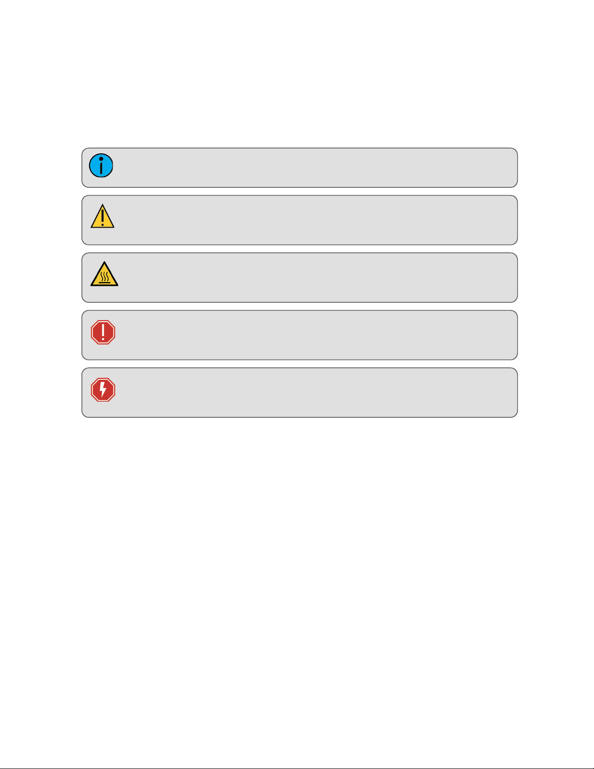
The following international note, caution, and warning symbols appear in margins throughout this manual to
highlight important messages.
Note: Notes are helpful hints and information that is supplemental to the main text.
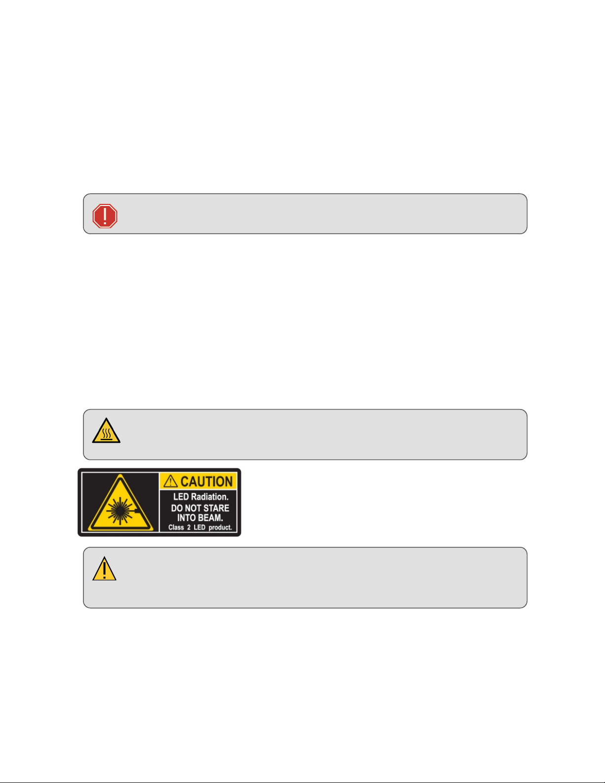
CAUTION: A Caution statement indicates situations where there may be undefined or
unwanted consequences of an action, potential for data loss or an equipment problem.
CAUTION: This statement indicates that while operating, equipment surfaces may
reach very high temperatures. Allow the fixture to cool before handling or servicing.
WARNING: A Warning statement indicates situations where damage may occur, people
may be harmed, or there are serious or dangerous consequences of an action.
WARNING: RISK OF ELECTRIC SHOCK! This warning statement indicates situations
where there is a risk of electric shock.
7
Page 12
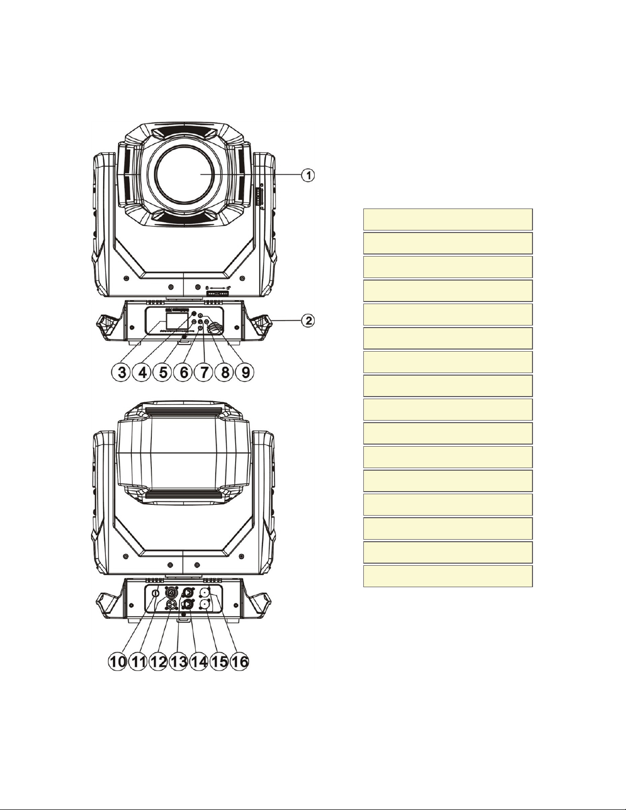
Fixture Overview
1: Lens
2: Handle
3: Display
4: [MODE/ESC] b utton
5: Left-button
6: Down-button
7: [Enter] bu tt on
8: Right-b ut ton
9: Up-b ut ton
10: Fuse
11: Power o ut
12: Power in
13: 5-Pin DMX out
14: 5-Pin DMX in
15: ART-NET in
16: ART-NET out
8
Page 13

Features
Optical
l LED: White 270 Watts
l Extremely long Life: >50,000 hours
l Color temperature: 7000 Kelvin
l Luminous flux: 11,300 lumens
l CRI of greater than 70
l Beam angle: Zoom from 6 to 50 degrees
l Strobe effect 1-25 HZ and pulse effect
l Motorized focus
l Dimmer: 0% - 100% full range dimming
Mechanical
l Pan and tilt motion with 8 or 16 bit control resolution
l Smooth, precise mechanical movement system supporting:
l Pan: 540° (630° optional)
l Tilt: 265°
l Variable speed pan and tilt motion
l Position memory, auto correction if fixture is bumped
Colors
l CMY & CTO variable color mixing for infinite color possibilities
l Color wheel including seven interchangeable dichroic filters + open, indexed, rainbow effect
Projection
l Rotating gobo wheel: including seven interchangeable rotating, and indexed, gobo + open
l “Slot in & out” gobo wheel system
l Rotating prism
l Stepless iris , 5% - 100% linear change iris, pulse iris effect
l Stepless frost, 0% - 100% linear change frost
l Animation wheel: special dynamic flame or water effects
Display
l Advanced full color LCD screen
l Internal rechargeable battery, enable users to access menu for address modification or other settings.
l Automatic lock out after 15 seconds (to prevent unintentional modifications)
l
Convenient position reset operation: hold the left-button and right-button (Complete this position
reset while the fixture is inside the flight case)
9
Page 14
Software
l Firmware upgrades are accomplished using a DMX cable with available hardware uploader
l Modify the DMX address, as well as other compatible features, using RDM control
l Standalone operation with Master / Slave function
l Control channel modes: 47 channels
Additional
l Input signal isolation: guarantees stable signal transmission without interference
l Advanced RDM function
l Patented lens defogger
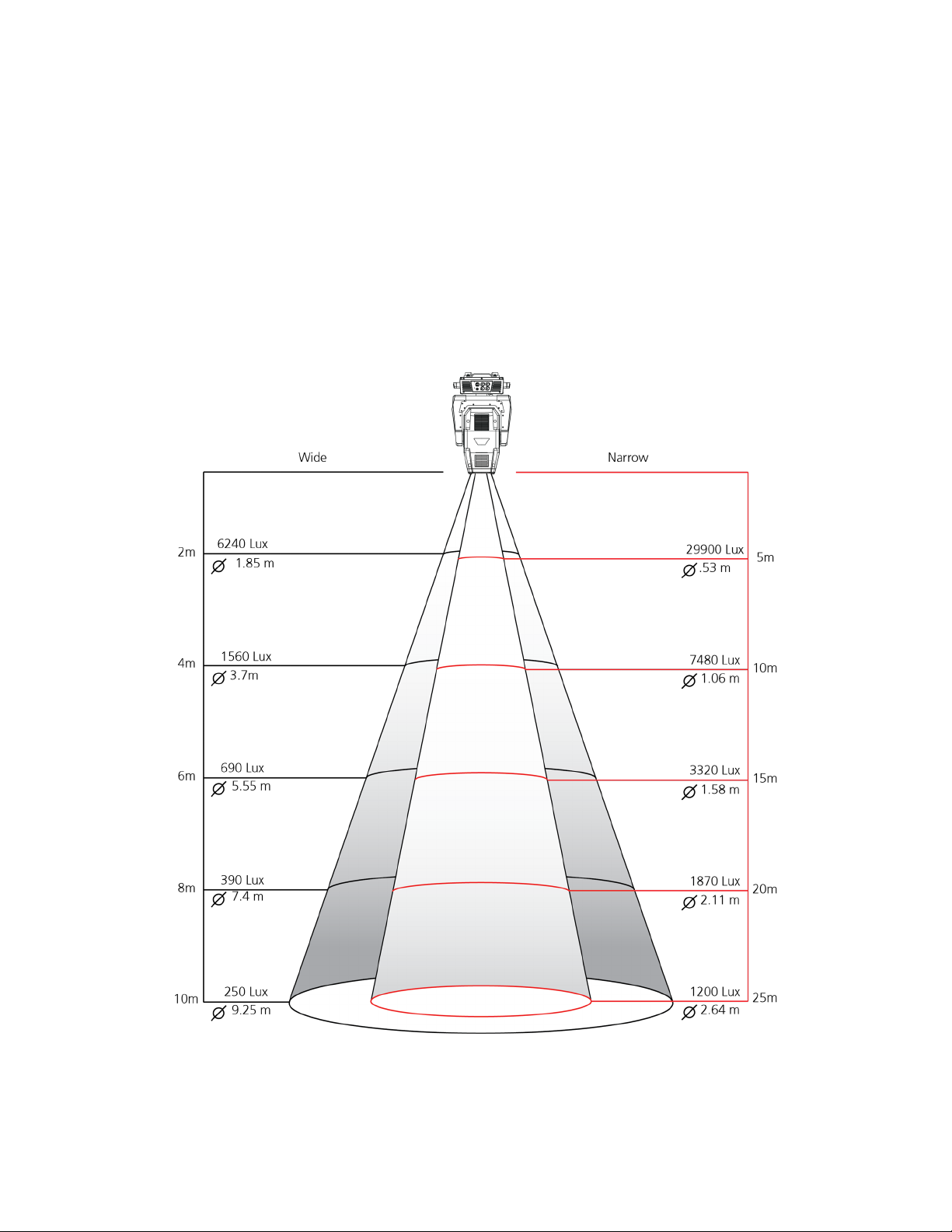
Zoom Range and Distance
10
Page 15
Safety Considerations
This fixture has left the factory in perfect condition. In order to maintain this condition and to ensure safe operation, it is necessary for the user to follow the safety instructions and warning notes written in this user manual
and otherwise instructed by the manufacturer representative.
l The SolaFrame 750 fixture is intended for professional use only. Not for residential use. Read the entire
manual before using this equipment.
l The SolaFrame 750 fixture is not user serviceable. Field modifications of the unit will void your warranty.
WARNING: For your safety, read the following warnings and notices before use:
l Disconnect the unit from power and DMX before servicing.
l Replace fuses with the specified type and rating only.
l Do not mount the fixture on or near flammable surfaces.
l NEMA Type 1 Enclosure, indoor use, dry locations only. Do not use outdoors. This fixture is intended for
use where humidity does not exceed 90% (non-condensing).
l This equipment is designed for operation by qualified personnel only.
l Do not use this fixture with a damaged power lead (cord set). If the lead is damaged, it must be replaced
with an equivalent type before use. Contact your local authorized dealer for spare power leads.
l Do not use this fixture if the lens is damaged. Damaged lenses must be replaced before use. Contact
your local authorized dealer for a replacement.
l When the fixture has been stored or transported in cold temperatures, allow it to warm to room tem-
perature for a minimum of one hour before applying power. Applying power to a cold fixture will cause
damage to the fixture and void the manufacturer warranty.
CAUTION: Hot Surfaces. Allow the fixture to cool completely before handling
and servicing.
CAUTION: Damages caused by the disregard of this user manual are not subject to
warranty. The authorized dealer will not accept liability for any resulting defects or
problems.
11
Page 16

General Operation and Use Guidelines
l This fixture is only allowed to be operated with the maximum alternating current which is stated in the
technical specifications label provided on the fixture and can be found in the Technical Specifications
on page17
l Lighting effects are not designed for permanent operation. Consistent operation breaks may ensure that
the device will serve you for a long time without defects.
l Do not shake the device. Avoid brute force when installing or operating the device.
l While choosing the installation location, please make sure that the device is not exposed to extreme
heat, moisture or dust.
l If you use the Omega bracket with quick lock cam in hanging the fixture, please make sure the quick lock
fasteners are turned in the quick lock holes correctly.
l Operate the fixture only after having familiarized yourself with its functions. Do not permit other persons
who are not qualified and familiar with its functions to operate the fixture. Most damages are the result of
unprofessional operation.
l Please use the original packaging if the device is to be transported. ETC and High End Systems, Inc. will
not be responsible for the unit if packaging other than manufacturer provided packaging is used.
l For safety reasons, please be aware that all modifications on the device are forbidden. Any modifications
will void the manufacturer warranty.
l This manual describes the proper installation and operation of this fixture. Using this fixture in any way
other than the intended use may cause damage and may void the factory warranty.
l Misuse of this fixture, using it in a way different to the methods described in this manual, may lead to per-
sonal injury and / or equipment failure.
12
Page 17

Installation Instructions
l The installation must always be secured with a secondary safety attachment. An appropriate safety
cable is supplied.
l A safety factor of 10:1 shall be required when fixtures are hung
l Use of third party clamps are permitted, but they should comply with the local jurisdiction and be
approved by the Authority Having Jurisdiction.
l A supportive and stable surface must be used when the fixtures are placed on the feet.
l The operating temperature range for this fixture is 0 - 45 degrees Celsius. Do not operate the fixture
outside of this range.
l Never stand directly below the installed fixture when mounting, removing, or servicing.
l All safety and technical aspects of fixture installation shall be approved by a qualified person before
operation.
l The installation must be regularly inspected by a qualified person.
l Overhead rigging must be performed by qualified personnel.
Attachment Instructions
CAUTION: Follow all local codes and recommended practices by the Authority Having
Jurisdiction (AHJ). The installation must only be carried out by a qualified person.
13
Page 18

1. Assemble the third party clamp or Omega clamp to the Omega bracket and secure together using appropriately sized hardware (not provided).
2. Align the assembled Omega bracket and quick lock fasteners into the respective holes on the bottom of
the fixture upper enclosure.
3. Tighten each of the quick lock fasteners fully, turning clockwise. You will hear and feel a click when the
fastener is fully secured.
4. Repeat steps 1 through 3 for the second clamp and bracket.
5. Attach the provided safety cable through the attachment point on the bottom of the fixture upper enclosure and secure to the trussing system or other safe installation point. Follow local codes and recommended safety standards for securing the fixture to the installation location.
6. Attach the fixture to the installation location using the installed clamps, using the clamp manufacturers
instructions for a secure fit. When using the Omega clamp, close the safety and fully tighten the clamp
wing nut until secure.
7. Inspect the installation prior to lifting the fixture over head.
14
Page 19

Dimensional Drawings
Dimensions shown are listed as mm [in].
15
Page 20

Mounting
Overhead mounting requires extensive experience, including but not limited to:
l calculating working load limits
l knowledge of the installation material being used
l periodic safety inspection of all installation material and the fixture
CAUTION: If you are not qualified, do not attempt the installation yourself. Improper
installation can result in bodily injury.
Note: Always use and install the supplied safety cable as a safety measure to prevent
accidental damage and/or injury in the event the clamp is improperly installed or fails.
Note: Do not mount the fixture on or near a flammable surface.
16
Page 21

Technical Specifications
Electrical
l Input power rating - 100-240 VAC, 50/60 Hz
SolaFrame 750 Po wer Factor
E (VAC) I (A) F (Hz) P (W) VA PF Crest F actor
100 5.619 50 562 0.578 0.99 1.49
120 4.519 60 542 0.558 0.99 1.52
200 2.7 50 540 0.531 0.98 1.54
208 2.558 60 532 0.539 0.98 1.54
220 2.43 50 535 0.536 0.98 1.54
240 2.264 60 543 0.537 0.98 1.51
l Maximum power consumption:562 W
l 33 dBA - full intensity, static position
Dimensions
l Reference Dimensional Drawings on page15.
Fixture Weight
l 28.6 Kg (63 lbs.)
Safety
l Minimum distance to flammable objects - 0.5 m (1.64 ft.)
l Minimum distance to lighted objects - 1.5 m (4.9 ft.)
CAUTION: RISKOF LED RADIATION. Do not stare into the beam.
17
Page 22

Environment
l Ambient temperature - 0-45° C (32-114°F)
l Storage temperature - -20° - 60° C (0-140°F)
Compliance
l CE
l ETL file number 3104374
l conforms to UL standard 1573
l certified to CSAstandard C22.2, NO:166
Mounting Options
l The SolaFrame 750 can be truss mounted using the provided mounting brackets and truss clamps (not
provided).
l The SolaFrame 750 can be used upright, on a stable surface.
18
Page 23

DMX Control
The SolaFrame 750 fixture operates on standard DMX512 control bus, controlled by a DMX console. A
SolaFrame 750 fixture requires 47 channels of DMX512. Attach the fixture to the control bus using a two-core,
shielded cable with a 5-pin XLR connector (Belden 9729 is preferred).
Two XLR termination receptacles are available, one for connection of DMXInput, and one for DMXOut (used
when daisy-chaining to additional fixtures on the DMX control bus).
DMX Connector Pinout
For DMXInput, the DMX cable must have a male XLR connector on one end of the cable. When daisy-chaining
DMX, the other end of the cable must have a female XLR connector. Terminate the cable ends as indicated in
the pinout graphic below.
Terminate DMX512
For installations where there is a long DMX cable run, or is in an electrically noisy environment, it is recommended to use a DMX terminator or install a resistor on the last fixture of the DMXcontrol run to prevent corruption (data reflection) of the digital control signal by electrical noise.
l A DMXterminator is an XLR plug with a 120 Ω resistor connected between pins 2 and 3, which can be
installed into the DMX output receptacle of the last fixture in the DMX control run. This plug is available
and sold separately. Contact your local High End dealer for ordering information.
l Alternatively, terminate the link by installing a 120 ohm, 1/4 watt (minimum) resistor in the fixture’s Data
Out (female) cable connector in the last fixture on each DMX control run.
Reference the graphics below:
19
Page 24

Connect DMXCables to Fixture
The following instructions are guidelines for connecting DMX to your fixture. Your installation may vary.
1. Connect the male XLR connector of a DMX data cable to the DMX Out connector on the DMX control
source.
2. Connect the female XLR connector of the DMX data cable to the Data In connector of the first fixture on
the DMX data control run.
3. Continue linking the remaining fixtures connecting a cable from the Data Out connector of each fixture to
the Data In connector of the next fixture on the link.
20
Page 25

DMX Start Address
All fixtures must be given a unique DMX starting address when using a DMX control signal, so that the correct fixture responds to the correct received control signals. This DMX start address is the channel number from which
the fixture starts to “listen” to the digital control information sent out from the DMX control source.
Modify the fixture DMX start address on the user interface, located on the upper enclosure. See Menu Settings
and Programming on page 23.
If you set the same address, all the units will “listen” to the same control signal from the same channel number. In
other words, changing the settings of one channel will affect all the fixtures simultaneously.
If you set a different address, each unit will start to “listen” to the channel number you have set, based on the
quantity of control channels of the unit. That means changing the settings of one channel will affect only the
selected fixture.
In the case of the moving head, which is a 47 channel fixture, you should set the starting address of the first unit
to 1, the second unit to 48 (47+ 1), the third to 95 (48+ 47), and so on.
21
Page 26

Menu Navigation and Overview
SolaFrame 750 fixtures can be programmed through the on board user interface and menu system. This section
describes how to navigate the menu using the user interface buttons as well as provides an overview of the
menu and the available settings for each selection.
Navigation
Note: The display is powered by battery when the fixture has no power. Press and hold
the [MODE/ESC] button for three seconds to turn on the display using battery power.
When the fixture is powered on, and no data signal is present after one minute of time has
lapsed, the display will switch off.
1. Press and hold the [MODE/ESC] button until the display flashes.
2. Browse the menu by pressing the up, down, left, or right navigation buttons.
3.
Press the Enter button to select a menu item.
4. Modify the selection by pressing the up, down, left, or right navigation buttons according to the selection.
5.
Press the Enter button to confirm a modified selection.
Note: 10 seconds after committing to a new mode or selection, and no further but-
tons are pressed, the unit will automatically return the display to the default display.
6. To exit the menu, press the [MODE/ESC] button.
22
Page 27

Menu Settings and Programming
This section details instructions to configure and set up the SolaFrame 750 using the provided user interface and
menu.
Note: The procedures below assume the fixture is powered.
Alternatively, when the fixture is not powered, the display is powered by battery. Press and
hold the [MODE/ESC] button for three seconds to turn on the display using battery power.
Address
Set the starting DMX address.
1. Press the [MODE/ESC] button to display the main menu.
2. Tap the [Up] or [Down] button until the “Address” option displays, then press [Enter]. The display will show
the Address menu with the current address (by default this is 001).
3. Tap the [Up] or [Down] button to change the starting DMX Address number.
4. Press [Enter] to confirm. The new address is set and the display returns to the main status screen. Alternatively, press [MODE/ESC] to return to the main menu without saving the address change.
23
Page 28

Info
Time Info.
Current Time
This menu displays the running time of the fixture from the last power on. The current value is shown in hours (h).
The counter resets after a power cycle.
1. Press the [MODE/ESC] button to display the main menu.
2. Tap the [Up] or [Down] button until the “Info” option displays, then press [Enter]. The "Info"menu displays.
3. Tap the [Up] or [Down] button until the “Time Info.” option displays, then press [Enter]. The "Time Info"
menu displays.
4. Tap the [Up] or [Down] button until the “Current Time” option displays, then press [Enter]. The current
power on running time of the fixture displays. All time is shown in hours.
5. Press [Enter] or press the [MODE/ESC] button to return to the previous menu.
Ttl Life Hrs
This menu displays the total running time of the device. The current value is shown in hours (h).
1. Press the [MODE/ESC] button to display the main menu.
2. Tap the [Up] or [Down] button until the “Info” option displays, then press [Enter]. The "Info"menu displays.
3. Tap the [Up] or [Down] button until the “Time Info.” option displays, then press [Enter]. The "Time Info"
menu displays.
4. Tap the [Up] or [Down] button until the “Ttl Life Hrs” option displays, then press [Enter]. The accumulated
fixture running time displays. All time is shown in hours.
5. Press [Enter] or press the [MODE/ESC] button to return to the previous menu.
24
Page 29

Last Run Hrs
This menu displays the running time of the lamp from the last power. The current value is shown in hours (h).
1. Press the [MODE/ESC] button to display the main menu.
2. Tap the [Up] or [Down] button until the “Info” option displays, then press [Enter]. The "Info"menu displays.
3. Tap the [Up] or [Down] button until the “Time Info.” option displays, then press [Enter]. The "Time Info"
menu displays.
4. Tap the [Up] or [Down] button until the “Last Run Hrs” option displays, then press [Enter]. The lamp running time since the last power on displays. All time is shown in hours.
5. Press [Enter] or press the [MODE/ESC] button to return to the previous menu.
LEDHours
This menu displays the total running hours of the fixture LEDs. The current value is shown in hours (h).
1. Press the [MODE/ESC] button to display the main menu.
2. Tap the [Up] or [Down] button until the “Info” option displays, then press [Enter]. The "Info"menu displays.
3. Tap the [Up] or [Down] button until the “Time Info.” option displays, then press [Enter]. The "Time Info"
menu displays.
4. Tap the [Up] or [Down] button until the “LED Hrs” option displays, then press [Enter]. The accumulated
time that LED's in the fixture have emitted light displays. All time is shown in hours.
5. Press [Enter] or press the [MODE/ESC] button to return to the previous menu.
Timer PIN
This menu displays and allows you to set the timer password. The default Timer PIN is "038".
1. Press the [MODE/ESC] button to display the main menu.
2. Tap the [Up] or [Down] button until the “Info” option displays, then press [Enter]. The "Info"menu displays.
3. Tap the [Up] or [Down] button until the “Time Info.” option displays, then press [Enter]. The "Time Info"
menu displays.
4. Tap the [Up] or [Down] button until the “Timer PIN” option displays, then press [Enter]. The "Timer PIN"
menu displays.
5. Tap the [Up] or [Down] button to change the pin value. The default PIN code is "038".
6. Press [Enter] to apply a change or press the [MODE/ESC] button to return to the previous menu.
Clr Last Run
This menu is protected by password, accessible only when the Timer PIN has been provided in the previous
menu. When accessed, this menu enables you to clear the last run time of the fixture.
1. Press the [MODE/ESC] button to display the main menu.
2. Tap the [Up] or [Down] button until the “Info” option displays, then press [Enter]. The "Info"menu displays.
3. Tap the [Up] or [Down] button until the “Time Info.” option displays, then press [Enter]. The "Time Info"
menu displays.
4. Tap the [Up] or [Down] button until the “Clr Last Run” option displays, then press [Enter].
5. Press the [Up] or [Down] button to change the setting to either Yes or No.
6. Press [Enter] to apply a change or press the [MODE/ESC] button to return to the previous menu.
LEDTime PIN
This menu displays and allows you to set the LED time password. The default LED Time PIN is "038".
25
Page 30

1. Press the [MODE/ESC] button to display the main menu.
2. Tap the [Up] or [Down] button until the “Info” option displays, then press [Enter]. The "Info"menu displays.
3. Tap the [Up] or [Down] button until the “Time Info.” option displays, then press [Enter]. The "Time Info"
menu displays.
4. Tap the [Up] or [Down] button until the “LED Timer PIN” option displays, then press [Enter]. The
"LEDTime PIN" menu displays.
5. Tap the [Up] or [Down] button to change the pin value. The default PIN code is "038".
6. Press [Enter] to apply a change or press the [MODE/ESC] button to return to the previous menu.
Clear LED Time
This menu is protected by password, accessible only when the LEDTimer PIN has been provided in the previous menu. When accessed, this menu enables you to clear the last run time of the fixtures LED timer.
1. Press the [MODE/ESC] button to display the main menu.
2. Tap the [Up] or [Down] button until the “Info” option displays, then press [Enter]. The "Info"menu displays.
3. Tap the [Up] or [Down] button until the “Time Info.” option displays, then press [Enter]. The "Time Info"
menu displays.
4. Tap the [Up] or [Down] button until the “Clear LED Time” option displays, then press [Enter].
5. Press the [Up] or [Down] button to change the setting to either Yes or No.
6. Press [Enter] to apply a change or press the [MODE/ESC] button to return to the previous menu.
Error Info
This menu displays all discovered errors related to the fixture.
1. Press the [MODE/ESC] button to display the main menu.
2. Tap the [Up] or [Down] button until the “Info” option displays, then press [Enter]. The "Info"menu displays.
3. Tap the [Up] or [Down] button until the “Error Info.” option displays, then press [Enter]. The current fixture
errors display.
4. Press [Enter] or press the [MODE/ESC] button to return to the previous menu.
DMXValue
This menu displays the DMX value of each of the fixture's channels and allows you to change a DMX value for a
channel (parameter of the fixture).
1. Press the [MODE/ESC] button to display the main menu.
2. Tap the [Up] or [Down] button until the “Info” option displays, then press [Enter]. The "Info"menu displays.
3. Tap the [Up] or [Down] button until the “DMX Value” option displays, then press [Enter]. The DMXValue
settings menu displays.
4. Tap the [Up] or [Down] button to cycle through the available channels (All, Pan, Tilt, etc.), then press
[Enter] to modify a selection. The current address displays for the selected channel.
5. Press the [Up] or [Down] button to edit the address setting.
6. Press [Enter] to apply a change or press the [MODE/ESC] button to return to the previous menu.
Head Temp
This menu displays the current fixture temperature as read from the fixture head (near the CMY filter).
1. Press the [MODE/ESC] button to display the main menu.
2. Tap the [Up] or [Down] button until the “Info” option displays, then press [Enter]. The "Info"menu displays.
3. Tap the [Up] or [Down] button until the “Head Temp” option displays, then press [Enter]. The current tem-
26
Page 31

perature is shown in Celsius by default. To change the scale to °F, reference the Set>Temp. C/F menu.
4. Press [Enter] or press the [MODE/ESC] button to return to the previous menu.
Fan Speed
This menu displays the speed of the fixture's fans. Values are shown in RPM.
1. Press the [MODE/ESC] button to display the main menu.
2. Tap the [Up] or [Down] button until the “Info” option displays, then press [Enter]. The "Info"menu displays.
3. Tap the [Up] or [Down] button until the “Fan Speed” option displays, then press [Enter]. Each of the four fixture fans in the fixture are displayed with their current speed (in RPM's).
4. Press [Enter] or press the [MODE/ESC] button to return to the previous menu.
Ethernet IP
This menu displays the current set fixture IPaddress information.
1. Press the [MODE/ESC] button to display the main menu.
2. Tap the [Up] or [Down] button until the “Info” option displays, then press [Enter]. The "Info"menu displays.
3. Tap the [Up] or [Down] button until the “Ethernet IP” option displays, then press [Enter]. The current fixture
Ethernet IP address information is shown.
4. Press [Enter] or press the [MODE/ESC] button to return to the previous menu.
Software Ver
This menu displays the current software version for the fixture.
1. Press the [MODE/ESC] button to display the main menu.
2. Tap the [Up] or [Down] button until the “Info” option displays, then press [Enter]. The "Info"menu displays.
3. Tap the [Up] or [Down] button until the “SoftwareVer” option displays, then press [Enter]. The current fixture software version is shown.
4. Press [Enter] or press the [MODE/ESC] button to return to the previous menu.
27
Page 32

Set
Status
No DMX Mode
This menu sets the function of the fixtures control when no DMX signal is present. Options include auto , close,
hold, and music. The default mode is hold.
1. Press the [MODE/ESC] button to display the main menu.
2. Tap the [Up] or [Down] button until the “Set” option displays, then press [Enter]. The "Set"menu displays.
3. Tap the [Up] or [Down] button until the “Status” option displays, then press [Enter]. The "Status" menu displays.
4. Press the [Up] or [Down] button until "No DMX Mode"displays, then press [Enter]. The current fixture control mode is shown.
5. Press [Up] or [Down] to modify the selection to a different mode.
6. Press [Enter] to commit to the change or press the [MODE/ESC] button to return to the previous menu.
28
Page 33

Pan Reverse
This menu provides access to reverse the fixture's pan movement.
1. Press the [MODE/ESC] button to display the main menu.
2. Tap the [Up] or [Down] button until the “Set” option displays, then press [Enter]. The "Set"menu displays.
3. Tap the [Up] or [Down] button until the “Status” option displays, then press [Enter]. The "Status" menu displays.
4. Press the [Up] or [Down] button until "Pan Reverse"displays, then press [Enter]. The current setting for
pan reverse displays (default setting is "Off").
5. Press [Up] or [Down] to modify the selection.
6. Press [Enter] to commit to the change or press the [MODE/ESC] button to return to the previous menu.
Tilt Reverse
This menu provides access to reverse the fixture's tilt movement.
1. Press the [MODE/ESC] button to display the main menu.
2. Tap the [Up] or [Down] button until the “Set” option displays, then press [Enter]. The "Set"menu displays.
3. Tap the [Up] or [Down] button until the “Status” option displays, then press [Enter]. The "Status" menu displays.
4. Press the [Up] or [Down] button until "Tilt Reverse"displays, then press [Enter]. The current setting for tilt
reverse displays (default setting is "Off").
5. Press [Up] or [Down] to modify the selection.
6. Press [Enter] to commit to the change or press the [MODE/ESC] button to return to the previous menu.
Pan Degree
This menu provides access to change the fixtures pan rotation from its default 540 degrees to 630 degrees.
1. Press the [MODE/ESC] button to display the main menu.
2. Tap the [Up] or [Down] button until the “Set” option displays, then press [Enter]. The "Set"menu displays.
3. Tap the [Up] or [Down] button until the “Status” option displays, then press [Enter]. The "Status" menu displays.
4. Press the [Up] or [Down] button until "Pan Degree"displays, then press [Enter]. The current setting for pan
degree displays (default setting is "540").
5. Press [Up] or [Down] to modify the selection.
6. Press [Enter] to commit to the change or press the [MODE/ESC] button to return to the previous menu.
Encoders
This menu provides access to switch encoder feedback for pan and tilt movement.
1. Press the [MODE/ESC] button to display the main menu.
2. Tap the [Up] or [Down] button until the “Set” option displays, then press [Enter]. The "Set"menu displays.
3. Tap the [Up] or [Down] button until the “Status” option displays, then press [Enter]. The "Status" menu displays.
4. Press the [Up] or [Down] button until "Encoders"displays, then press [Enter]. The current setting for feedback displays (default setting is "On").
5. Press [Up] or [Down] to modify the selection.
6. Press [Enter] to commit to the change or press the [MODE/ESC] button to return to the previous menu.
29
Page 34

Pan/Tilt Spd
This menu provides access to change the speed (scan mode) of pan and tilt movement.
1. Press the [MODE/ESC] button to display the main menu.
2. Tap the [Up] or [Down] button until the “Set” option displays, then press [Enter]. The "Set"menu displays.
3. Tap the [Up] or [Down] button until the “Status” option displays, then press [Enter]. The "Status" menu displays.
4. Press the [Up] or [Down] button until "Pan/Tilt Spd"displays, then press [Enter]. The current speed setting
displays.
5. Press [Up] or [Down] to modify the selection.
6. Press [Enter] to commit to the change or press the [MODE/ESC] button to return to the previous menu.
Hibernation - Standby mode
Hibernation mode forces the LEDs and stepper motors to power off when the fixture loses DMX control signal for
a set period of time. The default time setting is 15 minutes.
1. Press the [MODE/ESC] button to display the main menu.
2. Tap the [Up] or [Down] button until the “Set” option displays, then press [Enter]. The "Set"menu displays.
3. Tap the [Up] or [Down] button until the “Status” option displays, then press [Enter]. The "Status" menu displays.
4. Press the [Up] or [Down] button until "Hibernation"displays, then press [Enter]. The current setting displays. The default setting is "15 minutes").
5. Press [Up] or [Down] to modify the selection(1 - 99 minutes or set the mode to "Off").
6. Press [Enter] to commit to the change or press the [MODE/ESC] button to return to the previous menu.
Defogger
1. Press the [MODE/ESC] button to display the main menu.
2. Tap the [Up] or [Down] button until the “Set” option displays, then press [Enter]. The "Set"menu displays.
3. Tap the [Up] or [Down] button until the “Status” option displays then press [Enter]. The "Status" menu displays.
4. Press the [Up] or [Down] button until "Defogger"displays, then press [Enter]. The current setting displays.
The default setting is "Defog OnOP" which means the defogger is enabled when the LEDs are above 0%
intensity.
5. Press [Up] or [Down] to modify the selection. Options include "Defog OnOP" (when LEDs are above 0%
intensity), "Defog OnPwr" (always heating front lens when powered), and "Defog Off" (defogger is disabled).
6. Press [Enter] to commit to the change or press the [MODE/ESC] button to return to the previous menu.
Select Input
Set the control input for the fixture.
1. Press the [MODE/ESC] button to display the main menu.
2. Tap the [Up] or [Down] button until the “Set” option displays, then press [Enter]. The "Set"menu displays.
3. Tap the [Up] or [Down] button until the “Select Input” option displays, then press [Enter]. The "Select Input"
menu displays.
4. Press [Up] or [Down] to modify the selection (options include "DMXOnly", "Art-Net On IP2". "Art-Net On
IP10", or "sACN").
5. Press [Enter] to commit to the change or press the [MODE/ESC] button to return to the previous menu.
30
Page 35

Set Universe
1. Press the [MODE/ESC] button to display the main menu.
2. Tap the [Up] or [Down] button until the “Set” option displays, then press [Enter]. The "Set"menu displays.
3. Tap the [Up] or [Down] button until the “Select Universe” option displays, then press [Enter]. The "Select
Input" menu displays.
4. Press [Up] or [Down] to modify the selection (000 - 255).
5. Press [Enter] to commit to the change or press the [MODE/ESC] button to return to the previous menu.
Service Setting
The settings in the "Service Setting"menu are password protected. You must enter the Service PIN first, then
additional menu settings will be accessible.
Service PIN
The Service PIN is "050".
RDMUID
Remote Device Management, or RDM, requires that all RDM devices have a unique identifier (UID) that consists
of the manufacturer ID and serial number. Modifying this setting can break the RDM capability of this fixture.
There cannot be duplicate RDM UID on the same DMX control run as this will result in a data collision, causing a
communication failure. Ensure that all fixtures have a unique RDM UID if RDM functionality is to be used.
Note: If DMX splitters are used and RDM control is to be used, these splitters must sup-
port RDM.
1. Press the [MODE/ESC] button to display the main menu.
2. Tap the [Up] or [Down] button until the “Set” option displays, then press [Enter]. The "Set"menu displays.
3. Tap the [Up] or [Down] button until the “Service Setting” option displays, then press [Enter]. The "Service
Setting" menu displays.
4. Press the [Up] or [Down] button until "RDM UID"displays, then press [Enter]. If the Service PINhas not
been correctly applied in the previous menu, this menu will not be accessible. With successful Service
PIN entered, the current settings, manufacturer ID and fixture serial number, displays.
5. Press [Up] or [Down] to modify the fixture serial number to another setting. Do not duplicate RDMUID's in
a system as this will prevent the system from responding to RDMcommands.
6. Press [Enter] to commit to the change or press the [MODE/ESC] button to return to the previous menu.
Ethernet IP
1. Press the [MODE/ESC] button to display the main menu.
2. Tap the [Up] or [Down] button until the “Set” option displays, then press [Enter]. The "Set"menu displays.
3. Tap the [Up] or [Down] button until the “Service Setting” option displays, then press [Enter]. The "Service
Setting" menu displays.
4. Press the [Up] or [Down] button until "Ethernet IP"displays, then press [Enter]. If the Service PINhas not
been correctly applied in the previous menu, this menu will not be accessible. With successful Service
PIN entered, the current IP settings will display. The default IPaddress is 002-142.058.034 with the last
octet (034)selected for edit.
5. Use the [Left] or [Right] buttons to change the octet selected, and press the [Up] or [Down] button to
31
Page 36

modify the selected number to another setting.
6. Press [Enter] to commit to the change or press the [MODE/ESC] button to return to the previous menu.
Ether MaskIP (SubnetMask)
1. Press the [MODE/ESC] button to display the main menu.
2. Tap the [Up] or [Down] button until the “Set” option displays, then press [Enter]. The "Set"menu displays.
3. Tap the [Up] or [Down] button until the “Service Setting” option displays, then press [Enter]. The "Service
Settings" menu displays.
4. Press the [Up] or [Down] button until "Ether MaskIP"displays, then press [Enter]. If the Service PINhas not
been correctly applied in the previous menu, this menu will not be accessible. With successful Service
PIN entered, the current IP Subnet mask settings will display. The default Subnet mask address is 255-
000.000.000 with the last octet (000)selected for edit.
5. Use the [Left] or [Right] buttons to change the octet selected, and press the [Up] or [Down] button to
modify the selected number to another setting.
6. Press [Enter] to commit to the change or press the [MODE/ESC] button to return to the previous menu.
Clr Err Info
1. Press the [MODE/ESC] button to display the main menu.
2. Tap the [Up] or [Down] button until the “Set” option displays, then press [Enter]. The "Set"menu displays.
3. Tap the [Up] or [Down] button until the “Service Setting” option displays, then press [Enter]. The "Service
Settings" menu displays.
4. Press the [Up] or [Down] button until "Clr Err Info"displays, then press [Enter]. If the Service PINhas not
been correctly applied in the previous menu, this menu will not be accessible. With successful Service
PIN entered, the current setting will display. Off is the default setting.
5. Use the [Up] or [Down] buttons to change the selection.
6. Press [Enter] to commit to the change or press the [MODE/ESC] button to return to the previous menu.
Fans Mode Setting
1. Press the [MODE/ESC] button to display the main menu.
2. Tap the [Up] or [Down] button until the “Set” option displays, then press [Enter]. The "Set"menu displays.
3. Tap the [Up] or [Down] button until the “Fans Mode Setting” option displays, then press [Enter]. The "Fans
Mode Set" menu displays.
4. Use the [Up] or [Down] buttons to modify the setting ("Standard", "Studio", or "Continuous").
5. Press [Enter] to commit to the change or press the [MODE/ESC] button to return to the previous menu.
Disp. Setting
This menu provides user setting for the display features.
Shutoff Time
This menu sets the amount of time after the last user interface button press until the display goes to sleep. By
default, this setting is 5 minutes.
1. Press the [MODE/ESC] button to display the main menu.
2. Tap the [Up] or [Down] button until the “Set” option displays, then press [Enter]. The "Set"menu displays.
3. Tap the [Up] or [Down] button until the “Disp. Setting” option displays, then press [Enter]. The "Disp. Settings" menu displays.
4. Press the [Up] or [Down] button until "Shutoff Time"displays, then press [Enter]. The current shut off time
displays. By default this setting is 5 minutes.
32
Page 37
5. Use the [Up] or [Down] buttons to modify the selection (2 - 60 minutes).
6. Press [Enter] to commit to the change or press the [MODE/ESC] button to return to the previous menu.
Flip Display
This menu enables the display to be rotated 180°. Used for best user experience in a vertical installation.
1. Press the [MODE/ESC] button to display the main menu.
2. Tap the [Up] or [Down] button until the “Set” option displays, then press [Enter]. The "Set"menu displays.
3. Tap the [Up] or [Down] button until the “Disp. Setting” option displays, then press [Enter]. The "Disp. Settings" menu displays.
4. Press the [Up] or [Down] button until "Flip Display"displays, then press [Enter]. The current setting displays. By default this setting is set to "OFF".
5. Use the [Up] or [Down] buttons to modify the selection (ON will reverse the display 180° from a current
OFF setting).
6. Press [Enter] to commit to the change or press the [MODE/ESC] button to return to the previous menu.
Key Lock
This menu activates the automatic key lock feature, locking the user interface buttons from activity.
1. Press the [MODE/ESC] button to display the main menu.
2. Tap the [Up] or [Down] button until the “Set” option displays, then press [Enter]. The "Set"menu displays.
3. Tap the [Up] or [Down] button until the “Disp. Setting” option displays, then press [Enter]. The "Disp. Settings" menu displays.
4. Press the [Up] or [Down] button until "Key Lock"displays, then press [Enter]. The current setting displays.
By default this setting is set to "OFF".
5. Use the [Up] or [Down] buttons to modify the selection. When active, set to ON, the keys will be locked
automatically after exiting edit mode.
6. Press [Enter] to commit to the change or press the [MODE/ESC] button to return to the previous menu.
Note: To enable the user interface buttons again after enabling the key lock feature, press
and hold the [MODE/ESC] button for three seconds.
Temp. C/F
This menu provides settings for the temperature scale.
1. Press the [MODE/ESC] button to display the main menu.
2. Tap the [Up] or [Down] button until the “Set” option displays, then press [Enter]. The "Set"menu displays.
3. Tap the [Up] or [Down] button until the “Temp. C/F” option displays, then press [Enter]. The "Temp C/F"
menu displays and the current setting. "Celsius"is the default setting.
4. Use the [Up] or [Down] buttons to modify the selection.
5. Press [Enter] to commit to the change or press the [MODE/ESC] button to return to the previous menu.
ResetDefault
This menu resets the fixture settings to the factory defaults.
1. Press the [MODE/ESC] button to display the main menu.
2. Tap the [Up] or [Down] button until the “Set” option displays, then press [Enter]. The "Set"menu displays.
33
Page 38

3. Tap the [Up] or [Down] button until the “ResetDefault” option displays, then press [Enter]. The "ResetDefault" menu displays.
4. Use the [Up] or [Down] buttons to modify the selection.
5. Press [Enter] to commit to the change. When set to ON, the unit will reset to factory defaults, and return
the display to the default status screen. To exit without saving the change, press the [MODE/ESC] button
to return to the previous menu.
Test Menu
Home
This menu provides access to re-home the fixture or its mechanical features.
1. Press the [MODE/ESC] button to display the main menu.
2. Tap the [Up] or [Down] button until the “Test” option displays, then press [Enter]. The "Test"menu displays.
3. Tap the [Up] or [Down] button until the “Home” option displays, then press [Enter]. The "Home" menu displays.
4. Use the [Up] or [Down] buttons to modify the selection ("All" (all features in the fixture will re-home),
"Pan&Tilt" (re-homes only the pan and tilt), "Colors", "Gobos", and "Others", etc.).
5. Press [Enter] to commit to the change or press the [MODE/ESC] button to return to the previous menu.
Self Test
This menu provides access to run a self test program on the fixture.
1. Press the [MODE/ESC] button to display the main menu.
2. Tap the [Up] or [Down] button until the “Test” option displays, then press [Enter]. The "Test"menu displays.
3. Tap the [Up] or [Down] button until the “Self Test” option displays, then press [Enter]. The "Self Test" menu
displays and shows "Running" and the fixture will automatically begin a self test procedure, testing each
of the functions. This display will remain until the [MODE/ESC] button is pressed, which will return the display to the previous menu.
Test Channel
This menu provides access to automatically run a self test on each fixture channel individually.
34
Page 39

1. Press the [MODE/ESC] button to display the main menu.
2. Tap the [Up] or [Down] button until the “Test” option displays, then press [Enter]. The "Test"menu displays.
3. Tap the [Up] or [Down] button until the “Test Channel” option displays, then press [Enter]. The "Test Channel" menu displays with "Control" begin the first channel selected. The fixture automatically begins a self
test procedure for the extents of the fixture control features.
4. Press the [Up] or [Down] button to cycle through all fixture channels individually. As each channel is selected, the test will automatically begin for the displayed channel.
5. Press the [MODE/ESC] button to exit the "Test Channel" mode and return the display to the previous
menu.
Manual Ctrl.
This menu provides access to manually set each fixture channel value individually.
1. Press the [MODE/ESC] button to display the main menu.
2. Tap the [Up] or [Down] button until the “Test” option displays, then press [Enter]. The "Test"menu displays.
3. Tap the [Up] or [Down] button until the “Manual Ctrl.” option displays, then press [Enter]. The "Manual Ctrl"
menu displays.
4. Press the [Up] or [Down] button to cycle through the available fixture channels, and press [Enter] to select.
The selected fixture channel displays with the default channel value.
5. Press the [Up] or [Down] button to modify the value (000 - 255).
6. Press [Enter] to select the new value and return to the "Manual Ctrl" menu.
7. Press the [MODE/ESC] button to exit "Manual Ctrl."menu and return the display to the previous menu.
Calibration
This menu provides access to adjust the fixture's calibration features, modifying the home position. The calibration menu password is "050". This password must be supplied first, then the additional calibration menus will
be accessible.
1. Press the [MODE/ESC] button to display the main menu.
2. Tap the [Up] or [Down] button until the “Test” option displays, then press [Enter]. The "Test"menu displays.
3. Tap the [Up] or [Down] button until the “Calibration” option displays, then press [Enter]. The "Calibration"
menu displays.
4. Press [Enter] to select "Password" and use the [Up] button to select "050", then press [Enter]. The display
returns to the previous menu.
5. Press the [Up] or [Down] button to cycle through all available calibration features and press [Enter] to
select. The selection displays with the default channel value.
6. Press the [Up] or [Down] button to modify the value and press [Enter] to select and return to the "Calibration" menu.
7. Press the [MODE/ESC] button to exit the "Calibration"menu and return the display to the previous menu.
35
Page 40

Preset
PlayBack
This menu is provided to set the fixture's playback settings. Playback settings designate a fixture for
DMXControl, set to run an Auto Program as a master or in stand alone mode, or set for slave mode where playback information is received from a different master.
Preset programming requires one fixture to act as the Master. All other SolaFrame 750 fixtures on the link can
then be set a slaves to playback the designated master's presets. Slave fixtures receive all their preset parameter and timing information from the master fixture.
Example: The following example shows the relationship between programs, partitions, and scenes as
programmed on the Master and how slave fixtures are assigned.
Groups of scenes are edited into Programs 1– 10 on the fixture designated as Master
- Program 2 is assigned to Part 1
- Program 4 is assigned to Part 2
- Program 6 is assigned to Part 3
* F ixtures assigned as Slave 1 willplayback Part 1
* F ixtures assigned as Slave 2 willplayback Part 2
* F ixtures assigned as Slave 3 willplayback Part 3
1. Press the [MODE/ESC] button to display the main menu.
2. Tap the [Up] or [Down] button until the “Preset” option displays, then press [Enter]. The "Preset"menu displays.
3. Tap the [Up] or [Down] button until the “PlayBack” option displays, then press [Enter]. The "PlayBack"
menu displays.
4. Press the [Up] or [Down] button to cycle through all available playback options (listed below). Press
[Enter] to make the selection.
l DMX Control - reverts the function from Auto Program to DMX receive. Selecting this option
returns the display to the main status screen where DMXReceive will be displayed as the currently selected function.
36
Page 41

l Set to Slave - after a preset program is defined on a Master fixture, other SolaFrame 750 fixtures
on the same DMXdata link can be designated slaves to playback the configured Program (Part 1,
2, or 3) as defined on the Master fixture.
l Auto Program - sets the fixture to run an internal program alone or as a master. The program that
runs is determined under the "Select Prog." menu.
5. Press [Enter] to select or press the [MODE/ESC] button to return the display to the previous menu.
Select Prog.
This menu is provided to select the auto program the fixture will run.
1. Press the [MODE/ESC] button to display the main menu.
2. Tap the [Up] or [Down] button until the “Preset” option displays, then press [Enter]. The "Preset"menu displays.
3. Tap the [Up] or [Down] button until the “Select Prog.” option displays, then press [Enter]. The "Select
Prog"menu displays.
4. Tap the [Up] or [Down] button to cycle through and select from the available program options (Prog.
Part1, ... Part2, etc.), then press [Enter].
5. Press the [Up] or [Down] button to choose the Program to run for the selected part, then press [Enter]. The
display returns to the main menu.
Edit Program
This menu is provided to edit the steps in the internal auto programs.
1. Press the [MODE/ESC] button to display the main menu.
2. Tap the [Up] or [Down] button until the “Preset” option displays, then press [Enter]. The "Preset"menu displays.
3. Tap the [Up] or [Down] button until the “Edit Program” option displays, then press [Enter]. The "Edit
Program"menu displays.
4. Tap the [Up] or [Down] button to cycle through and select from the available program options (Program 1,
Program 2, etc.), then press [Enter]. The "Edit Program" menu displays.
5. Press the [Up] or [Down] button to choose the first step to edit from the available options, then press
[Enter].
6. Press the [Up] or [Down] button to select the program action from the available options, then press [Enter].
7. Repeat for each step if desired. Press [Enter] with each edit.
8. To return to the main menu, press the [MODE/ESC] button.
37
Page 42

Edit Scenes
A parameter is a fixture attribute that can be controlled, for example to modify the light beam in terms of color,
beam quality and pattern, intensity, or focus (position). DMX programming assigns a DMX value to each of the fixture’s parameters. A scene is one combination of parameter settings. The SolaFrame 750 fixture provides 250
pre-programmed scenes you can use or edit to build a preset program.
This menu is provided to edit the scenes in the internal auto programs.
1. Press the [MODE/ESC] button to display the main menu.
2. Tap the [Up] or [Down] button until the “Preset” option displays, then press [Enter]. The "Preset"menu displays.
3. Tap the [Up] or [Down] button until the “Edit Scenes” option displays, then press [Enter]. The "Edit
Scenes"menu displays.
4. Tap the [Up] or [Down] button to cycle through and select from the available scene options (Scene 1,
Scene 2, etc.), then press [Enter]. The "Edit Scenes" menu displays and the fixture responds to the selected scene.
5. Press the [Up] or [Down] button to scroll the available channel feature and press [Enter]. The channel
value displays for edit.
6. Press the [Up] or [Down] button to change the channel value, then press [Enter].
7. Repeat for each scene if desired. Press [Enter] with each edit.
8. To return to the main menu, press the [MODE/ESC] button.
Scenes Input
This menu allows you to capture scene data, overwriting fixture attribute DMXparameter values, from a
DMXcontrol source.
1. Press the [MODE/ESC] button to display the main menu.
2. Tap the [Up] or [Down] button until the “Preset” option displays, then press [Enter]. The "Preset"menu displays.
3. Tap the [Up] or [Down] button until the “Scenes Input” option displays, then press [Enter]. The "Scenes
Input"menu displays.
4. Press the [Up] or [Down] button to select the start scene number and the [Left] or [Right] button to select
the end scene number. With each change of any DMX value, as received by the DMXcontrol source, the
capturing scene will advance to the next one in the range.
5. When all scenes have been recorded, the display will return to the main menu.
Note: While capturing the DMX data from the control source, the SolaFrame 750 does not
playback the DMXinput, it only captures the data into the on-board memory. You must edit
or playback the scene after recording to verify the results. Best practice is to prepare the
scenes on a DMX controller with a zero crossfade for all parameters between each step.
Remember that any change of a DMXvalue will automatically advance to the next scene
for capturing.
38
Page 43

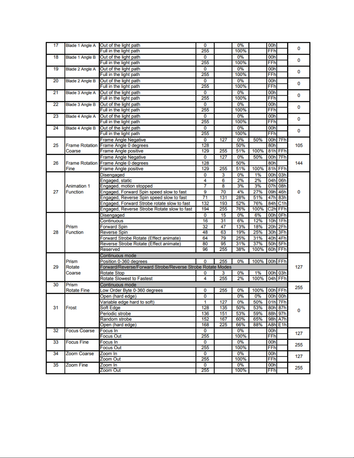
DMX Control Protocol
The most current DMXControl Protocol data for the SolaFrame 750 can be found on the High End Systems, Inc. website https://www.highend.com/SolaFrame750-DMXProtocol.
The following data is current as of protocol version 1.00
394041
Page 44

Page 45
Page 46

42
Page 47

Protocol Notes
1. Continuous mode should take quickest path from 255-0, and 0-255.
l Continuous mode color wheel aperture centers:
2. 15 Discrete multi-step LED animations. These require macro speed and x fade channels. The macros will
operate independently. The X fade and speed channels act as multipliers of the programmed speed in
the discrete macro steps.
l Speed / X fade channel operation
l 0 stops playback or crossfade
l 1-127 decreases playback speed / crossfade time (* <1)
l 128 playback or cross fade speed is as programmed (*1)
l 129-255 increases playback speed / crossfade time (* >1)
43
Page 48

Error Codes
When you turn on the fixture, it will complete a start-up procedure.
Example: For example, when the display shows “Err Info: Pan Movement”, it
means there is an error in channel 1. When multiple errors are present they will cycle
on the display twice, then the fixture will generate a second reset. Any errors that
remain after two reset cycles are not correctable by reset alone and will require service. Please contact support if detailed assistance is needed.
Pan movement
This message displays after the reset of the fixture if any of the following conditions exist:
l if the yoke’s magnetic-indexing circuit malfunctions (optical or magnetic sensor failure)
l if the stepper motor is defective or the related IC driver on the main PCB has failed
l if the Pan movement is not located in the default position after the reset
Tilt movement
This message displays after the reset of the fixture if any of the following conditions exist:
l if the fixture head magnetic-indexing circuit malfunctions (optical or magnetic sensor failure)
l if the stepper motor is defective or the related IC driver on the main PCB has failed
l if the Tilt movement is not located in the default position after the reset
Color1
This message displays after the reset of the fixture if any of the following conditions exist:
l if the fixture head's magnetic-indexing circuit malfunctions (optical or magnetic sensor failure)
l if the stepper motor is defective or the related IC driver on the main PCB has failed
l if the Color wheel movement is not located in the default position after the reset
Cyan, Magenta, or Yellow Color
This message displays after the reset of the fixture if any of the following conditions exist:
l if the fixture head's magnetic-indexing circuit malfunctions (optical or magnetic sensor failure)
l if the stepper motor is defective or the related IC driver on the main PCB has failed
l if the CMY movement is not located in the default position after the reset
CTO Color
This message displays after the reset of the fixture if any of the following conditions exist:
l if the fixture head's magnetic-indexing circuit malfunctions (optical or magnetic sensor failure)
l if the stepper motor is defective or the related IC driver on the main PCB has failed
l if the CTO movement is not located in the default position after the reset
44
Page 49

Gobo1
This message displays after the reset of the fixture if any of the following conditions exist:
l if the magnetic-indexing circuit malfunctions (optical or magnetic sensor failure)
l if the stepper motor is defective or the related IC driver on the main PCB has failed
l if Gobo Wheel 1 is not located in the default position after the reset
Gobo1Rot
This message displays after the reset of the fixture if any of the following conditions exist:
l if the magnetic-indexing circuit malfunctions (optical or magnetic sensor failure)
l if the stepper motor is defective or the related IC driver on the main PCB has failed
l if Gobo Rotating Wheel 1 is not located in the default position after the reset
Focus
This message displays after the reset of the fixture if any of the following conditions exist:
l if the magnetic-indexing circuit malfunctions (optical or magnetic sensor failure)
l if the stepper motor is defective or the related IC driver on the main PCB has failed
l if the Focus movement is not located in the default position after the reset
Zoom
This message displays after the reset of the fixture if any of the following conditions exist:
l if the magnetic-indexing circuit malfunctions (optical or magnetic sensor failure)
l if the stepper motor is defective or the related IC driver on the main PCB has failed
l if the Zoom movement is not located in the default position after the reset
Frost
This message displays after the reset of the fixture if any of the following conditions exist:
l if the magnetic-indexing circuit malfunctions (optical or magnetic sensor failure)
l if the stepper motor is defective or the related IC driver on the main PCB has failed
l if the Frost movement is not located in the default position after the reset
45
Page 50

Animation1
This message displays after the reset of the fixture if any of the following conditions exist:
l if the magnetic-indexing circuit malfunctions (optical or magnetic sensor failure)
l if the stepper motor is defective or the related IC driver on the main PCB has failed
l if the Animation movement is not located in the default position after the reset
Blade1
This message displays after the reset of the fixture if any of the following conditions exist:
l if the magnetic-indexing circuit malfunctions (optical or magnetic sensor failure)
l if the stepper motor is defective or the related IC driver on the main PCB has failed
l if the Blade Rotation movement is not located in the default position after the reset
46
Page 51

Cleaning and Maintenance
The following must be considered during regular service and inspection:
l All screws for installing the device or parts of the device must be tightly connected and must not be cor-
roded.
l There must not be any deformations to the housing, lenses, rigging, and installation points (ceiling, sus-
pension, trussing).
l Motorized parts must not show any signs of wear and must move smoothly without issue.
l The power supply cables must not show any damage, material fatigue or sediment.
Note: Further instructions depending on the installation location and usage must be
adhered to by a qualified installer and all safety concerns must be mitigated.
CAUTION: Disconnect the fixture from mains power before starting any maintenance
procedures.
In order to ensure the device remains in good working condition and does not fail prematurely, regular maintenance is recommended.
1. Clean the inside and outside lens regularly to avoid loss of output due to accumulation of dust/ dirt on the
lens.
2. Clean the fans regularly to ensure maximum airflow and efficient thermal cooling. This will ensure the
light source is operated in the best possible condition.
Note: ETC and High End Systems, Inc. recommends frequent cleaning of the device.
Please use a moist, lint- free cloth. Never use alcohol or solvents.
If spare parts are required, order only genuine parts from your local authorized dealer.
47
Page 52

Headquarters ● 2105 Gracy Farms Lane, Austin, TX, 75758 USA
Tel +512 836 2242 ● Fax +512 837 5290 ● 24 Hour Urgent Support: +512 836 2242
Web: highend.com ● © 2017 Electronic Theatre Controls, Inc.
Product information and specifications subject to change. ETCintends this document to be
provided in its entirety.
SolaFrame 750 User Manual ● Rev A ● Released 2017-10
 Loading...