

Page 1
StudioPix™ Pixelation Luminaire
User Manual
© High End Systems, Inc. 2008, All Rights Reserved
Information and specifications in this document are subject to change without notice. High End Systems, Inc.
assumes no responsibility or liability for any errors or inaccuracies that may appear in this manual.
Trademarks used in this text: High End Systems, and Wholehog are registered trademarks; and SHOWPIX,
Echo, DMX Scratch, Internal Effect, the High End Systems globe logo and the Hog logo are trademarks of High
End Systems, Inc. or High End Systems Europe Ltd. Belden is a registered trademark of Belden, Inc.
Microsoft, DirectX, and Windows are either registered trademarks or trademarks of Microsoft Corporation in
the United States and/or other countries.
Other trademarks and trade names may be used in this document to refer to either the entities claiming the
marks and names or their products. High End Systems disclaims any proprietary interest in trademarks and
trade names owned by others.
StudioPix™ User Manual
October, 2008
i
Page 2

Contacting High End Systems
®
Sales Department High End Systems, Inc.
2105 Gracy Farms Lane
Austin, TX 78758 USA
voice: 512.836.2242
fax: 512.837.5290
Toll Free: 800.890.8989
Customer Service High End Systems, Inc.
2105 Gracy Farms Lane
Austin, TX 78758 USA
voice: 800.890.8989
fax: 512.834.9195
toll free: 800.890.8989
email: support@highend.com
World Wide Web: http://www.highend.com
Patents
This High End Systems product is protected by patents and pending patent applications.
Patents
US 4,392,187; US 4,602,321; US 4,688,161; US 4,701,833; US 4,709,311; US 4,779,176; US 4,800,474;
US
US
US
US
US
US
US
US
US
US
US
US
US
US
US
US
US
US
US
US
US
US
US
US
US
US
AT
DE
DK
EP
GB
GB
IT
UK
owned or licensed by High End Systems include:
4,962,687; US 4,972,306; US 4,980,806; US 5,010,459; US 5,031,078; US 5,073,847; US 5,078,039;
5,186,536; US 5,209,560; US 5,278,742; US 5,282,121; US 5,307,295; US 5,329,431; US 5,331,822;
5,367,444; US 5,402,326; US 5,414,328; US 5,426,576; US 5,430,629; US 5,432,691; US 5,454,477;
5,455,748; US 5,502,627; US 5,506,762; US 5,515,254; US 5,537,303; US 5,545,951; US 5,588,021;
5,590,954; US 5,590,955; US 5,640,061; US 5,647,662; US 5,691,886; US 5,702,082; US 5,728,994;
5,758,955; US 5,758,956; US 5,769,527; US 5,769,531; US 5,774,273; US 5,788,365; US 5,794,881;
5,795,058; US 5,798,619; US 5,806,951; US 5,812,596; US 5,823,661; US 5,825,548; US 5,828,485;
5,829,868; US 5,857,768; US 5,882,107; US 5,921,659; US 5,934,794; US 5,940,204; US 5,945,786;
5,953,151; US 5,953,152; US 5,969,485; US 5,980,066; US 5,983,280; US 5,984,248; US 5,986,201;
6,011,662; US 6,029,122; US 6,048,080; US 6,048,081; US 6,054,816; US 6,057,958; US 6,062,706;
6,079,853; US 6,126,288; US 6,142,652; US 6,142,653; US 6,172,822; US 6,175,771; US 6,188,933;
6,208,087; US 6,219,093; US 6,220,730; US 6,241,366; US 6,249,091; US 6,255,787; US 6,256,136;
6,261,636; US 6,278,542; US 6,278,545; US 6,278,563; US 6,288,828; US 6,326,741; US 6,327,103;
6,331,756; US 6,346,783; US 6,421,165; US 6,430,934; US 6,459,217; US 6,466,357; US 6,502,961;
6,515,435; US 6,523,353; US 6,536,922; US 6,538,797; US 6,545,586; US 6,549,324; US 6,549,326;
6,563,520; US 6,565,941; US 6,570,348; US 6,575,577; US 6,578,991; US 6,588,944; US 6,592,480;
6,597,132; US 6,600,270; US 6,601,974; US 6,605,907; US 6,617,792; US 6,621,239; US 6,622,053;
6,635,999; US 6,648,286; US 6,664,745; US 6,682,031; US 6,693,392; US 6,696,101; US 6,719,433;
6,736,528; US 6,771,411; US 6,775,991; US 6,783,251; US 6,801,353; US 6,812,653; US 6,823,119;
6,865,008; US 6,866,390; US 6,866,402; US 6,866,451; US 6,869,193; US 6,891,656; US 6,894,443;
6,919,916; US 6,930,456; US 6,934,071; US 6,937,338; US 6,955,435; US 6,969,960; US 6,971,764;
6,982,529; US 6,988,805; US 6,988,807; US 6,988,817; US 7,000,417; US 7,011,429; US 7,018,047;
7,020,370; US 7,033,028; US 7,048,838; US 7,055,963; US 7,055,964; US 7,057,797; US 7,073,910;
7,078,869; US 7,092,098; US 7,119,902; US 7,161,562; US 7,175,317; US 7,181,112; US 7,206.023;
7,210,798; US 7,253,942; US D347,113; US D350,408; US D359,574; US D360,404; US D365,165;
D366,712; US D370,080; US D372,550; US D374,439; US D377,338; US D381,740; US D409,771;
E169413; CA 2142619; CA 2145508; CA 2245842; DE 22588.4-08; DE 621495; DE 655144;
69320175.4; DE 69322401.0; DE 69331145.2; DE 69525856.7; DE 69734744.3; DE 797503;
0655144; DK 1447702; EP 0475082; EP 0621495; EP 0655144; EP 0662275; EP 0767398; EP 0797503;
0969247; EP 1447702; ES 0621495; FR 0621495; FR 0655144; FR 0662275; FR 1447702; GB 2043769B;
2055842B; GB 2283808B; GB 2290134B; GB 2291814B; GB 2292530B; GB 2292896B; GB 2294909B;
2295058B; GB 2303203B; GB 2306887B; GB 2307036B; GB 2316477B; IE 0621495; IT 034244BE; 2005;
0621495; IT 0655144; JP 3495373; JP 3793577; NL 0621495; NL 0797503; NL 0969247; UK 0621495;
0655144; UK 0662275; UK 0797503; UK 0969247; UK 1447702;
ii StudioPix™ Pixelation Luminaire User Manual
Page 3

Declaration of Conformity
according to ISO/IEC Guide 22 and EN45104
Manufacturer’s name: High End Systems, Inc.
Distributor’s name: High End Systems, Inc.
Distributor’s address: 2105 Gracy Farms Lane
Declares that the product:
Product Name: StudioPix
Product Number: All
Product Options: All
conforms to the following EEC directives:
73/23/EEC, as amended by 93/68/EEC
89/336/EEC, as amended by 92/31/EEC and 93/68/EEC
Equipment referred to in this declaration of conformity was first manufactured in compliance
with the following standards in 2005:
Safety: EN 60598-1: 1997
EN 60598-2-17; 1990
A1-A3: 1998
A13: 1999
EMC:
EN 55022
Conducted Emissions Class A
Radiated Emissions Class A
ANSI C63.4 Class A
FCC 47 CFR Part 15 Class A
VCCI V-1/2001.04 Class A
EN 55024
EN 61000-4-2 4/8kV
EN 61000-4-3 A1 3V/m
EN 61000-4-4 1kV/0.5kV
EN 61000-4-5 2kV/1kV
EN 61000-4-6 3 Vrms
EN 61000-4-11 >95%-0.5p, 30%-25p,>95%-250p
EN 61000-3-2 Class A
EN 61000-3-3
Austin, Texas 78758 USA
USA, Thursday, October 02, 2008
Kenneth Stuart Hansen, Compliance Engineer
StudioPix™ Pixelation Luminaire User Manual iii
Page 4

Product Modification Warning
High End Systems products are designed and manufactured to meet the requirements of United States and
International safety regulations. Modifications to the product could affect safety and render the product noncompliant to relevant safety standards.
Mise En Garde Contre La Modification Du Produit
Les produits High End Systems sont conçus et fabriqués conformément aux exigences des règlements
internationaux de sécurité. Toute modification du produit peut entraîner sa non conformité aux normes de
sécurité en vigueur.
Produktmodifikationswarnung
Design und Herstellung von High End Systems entsprechen den Anforderungen der U.S. Amerikanischen und
internationalen Sicherheitsvorschriften. Abänderungen dieses Produktes können dessen Sicherheit
beeinträchtigen und unter Umständen gegen die diesbezüglichen Sicherheitsnormen verstoßen.
Avvertenza Sulla Modifica Del Prodotto
I prodotti di High End Systems sono stati progettati e fabbricati per soddisfare i requisiti delle normative di
sicurezza statunitensi ed internazionali. Qualsiasi modifica al prodotto potrebbe pregiudicare la sicurezza e
rendere il prodotto non conforme agli standard di sicurezza pertinenti.
Advertencia De Modificación Del Producto
Los productos de High End Systems están diseñados y fabricados para cumplir los requisitos de las reglamentaciones de seguridad de los Estados Unidos e internacionales. Las modificaciones al producto podrían afectar
la seguridad y dejar al producto fuera de conformidad con las normas de seguridad relevantes.
FCC Information
This equipment has been tested and found to comply with the limits for a Class A digital device, pursuant to
part 15 of the FCC rules. These limits are designed to provide reasonable protection against harmful
interference when the equipment is operated in a commercial environment. This equipment generates, uses,
and can radiate radio frequency energy and, if not installed and used in accordance with the instruction
manual, may cause harmful interference to radio communications. Operation of this equipment in a residential
area is likely to cause harmful interference, in which case the user will be required to correct the interference
at his own expense.
Important Safety Information
Instructions pertaining to continued protection against fire, electric shock, and injury to persons are found in
Appendix B. Please read all instructions prior to assembling, mounting, and operating this equipment.
Important: Informations De Sécurité
Les instructions se rapportant à la protection permanente contre les incendies, l’électrocution, excessif et aux
blessures corporelles se trouvent dans l’Annexe B. Veuillez lire toutes les instructions avant d’assembler, de
monter ou d’utiliser cet équipement.
Wichtige Sicherheitshinweise
Sicherheitsanleitungen zum Schutz gegen Feuer, elektrischen Schlag, und Verletzung von Personen finden Sie
in Anhang B. Vor der Montage, dem Zusammenbau und der Intbetriebnahme dieses Geräts alle Anleitungen
sorgfältig durchlesen.
Informazioni Importanti Di Sicurezza
Le istruzioni sulla protezione da incendi, folgorazione, e infortuni sono contenute nell’appendice B. Si prega di
leggere tutte le istruzioni prima di assemblare, montare e azionare l’apparecchiatura.
Informacion Importante De Seguridad
En el Apéndice B se encuentran instrucciones sobre protección continua contra incendios, descarga eléctrica, y
lesiones personales. Lea, por favor, todas las instrucciones antes del ensamblaje, montaje y operación de este
equipo.
iv StudioPix™ Pixelation Luminaire User Manual
Page 5
Symbols
The following international caution and warning symbols appear in margins throughout this manual to
highlight messages.
CAUTION: This symbol appears adjacent to Caution
messages. Not heeding these messages could result in
personal injury and/or damage to equipment.
WARNING: This symbol appears adjacent to high
voltage warning messages. Not heeding these
messages could result in serious personal injury.
This symbol indicates the minimum distance from a
lighted object
Warranty Information
Limited Warranty
Unless otherwise stated, your product is covered by a one year parts and labor limited warranty. It is the
owner’s responsibility to furnish receipts or invoices for verification of purchase, date, and dealer or
distributor. If purchase date cannot be provided, date of manufacture will be used to determine warranty
period.
Returning an Item Under Warranty for Repair
It is necessary to obtain a Return Material Authorization (RMA) number from your dealer or point of purchase
BEFORE any units are returned for repair. The manufacturer will make the final determination as to whether or
not the unit is covered by warranty.
Any Product unit or parts returned to High End Systems must be packaged in a suitable manner to ensure the
protection of such Product unit or parts, and such package shall be clearly and prominently marked to indicate
that the package contains returned Product units or parts and with an RMA number. Accompany all returned
Product units or parts with a written explanation of the alleged problem or malfunction. Ship returned Product
units or parts to: 2105 Gracy Farms Lane, Austin, TX 78758 USA.
Note: Freight Damage Claims are invalid for fixtures shipped in non-factory boxes and packing materials.
Freight
All shipping will be paid by the purchaser. Items under warranty shall have return shipping paid by the
manufacturer only in the Continental United States. Under no circumstances will freight collect shipments be
accepted. Prepaid shipping does not include rush expediting such as air freight. Air freight can be sent
customer collect in the continental United States.
REPAIR OR REPLACEMENT AS PROVIDED FOR UNDER THIS WARRANTY IS THE EXCLUSIVE REMEDY OF THE
CONSUMER OTHER THAN THE LIMITED WARRANTY STATED ABOVE. HIGH END SYSTEMS, INC. MAKES NO
WARRANTIES, EXPRESS OR IMPLIED, WITH RESPECT TO ANY PRODUCT, AND HIGH END SPECIFICALLY
DISCLAIMS ANY WARRANTY OF MERCHANTABILITY OR FITNESS FOR A PARTICULAR PURPOSE. HIGH END
SHALL NOT BE LIABLE FOR ANY INDIRECT, INCIDENTAL OR CONSEQUENTIAL DAMAGE, INCLUDING LOST
PROFITS, SUSTAINED OR INCURRED IN CONNECTION WITH ANY PRODUCT OR CAUSED BY PRODUCT
DEFECTS OR THE PARTIAL OR TOTAL FAILURE OF ANY PRODUCT REGARDLESS OF THE FORM OF ACTION,
WHETHER IN CONTRACT, TORT (INCLUDING NEGLIGENCE), STRICT LIABILITY OR OTHERWISE, AND
WHETHER OR NOT SUCH DAMAGE WAS FORESEEN OR UNFORESEEN.
Warranty is void if the product is misused, damaged, modified in any way, or for unauthorized repairs or parts.
This warranty gives you specific legal rights, and you may also have other rights specific to your locality.
StudioPix™ Pixelation Luminaire User Manual v
Page 6

vi StudioPix™ Pixelation Luminaire User Manual
Page 7

Table of Contents
StudioPix™ Pixelation Luminaire User Manual ...................................................... i
Contacting High End Systems® .............................................................................ii
Patents ..............................................................................................................ii
Declaration of Conformity ....................................................................................iii
Product Modification Warning ...............................................................................iv
FCC Information .................................................................................................iv
Important Safety Information ...............................................................................iv
Symbols ............................................................................................................ v
Warranty Information .......................................................................................... v
Chapter 1: Product Overview
This chapter describes the features of the StudioPix™ Pixelation
Luminaire with custom content and Echo software.
Features .............................................................................................................. 1
System ............................................................................................................. 1
Graphics Engine ................................................................................................. 2
Operation .......................................................................................................... 2
Construction ...................................................................................................... 3
Echo Software .................................................................................................... 3
Related Products and Accessories ....................................................................... 3
Specifications ...................................................................................................... 4
Mechanical Specifications ..................................................................................... 4
Mounting Information .......................................................................................... 4
Electrical/Light Source Specifications ..................................................................... 5
Operation .......................................................................................................... 5
Chapter 2: Setup and Configuration
StudioPix™ fixture setup includes mounting, connecting to power
and DMX linking and configuration.
Unpacking the Fixture ......................................................................................... 7
Installing a Power Cord Cap ................................................................................ 7
Installing a Line Cord Cap - U.K. Only .................................................................... 8
Vatic Fitter Heads Information - Danmark .............................................................. 8
Mounting the Fixture ........................................................................................... 8
Mounting the Fixture Upright ................................................................................ 8
Truss Mounting .................................................................................................. 9
Safety Cable ................................................................................................... 9
Clamp ............................................................................................................ 9
Mounting Procedure ......................................................................................... 9
StudioPix™ Pixelation Luminaire User Manual vii
Page 8

Linking StudioPix Fixtures ................................................................................. 10
Cable Connectors .............................................................................................. 10
Connecting to the Link ....................................................................................... 11
Powering On the Fixture .................................................................................... 11
Setting the DMX Start Channel ........................................................................... 12
Shutting Down the Fixture ................................................................................. 13
Chapter 3: The Menu System
You can use the fixture’s onboard menu system to configure and
test the StudioPix fixture.
Navigating the Menu System ............................................................................. 15
StudioPix Menu Map .......................................................................................... 16
StudioPix Menu Options ..................................................................................... 17
Set Menu (SET) ................................................................................................ 17
Setting Factory Defaults (FACT) ....................................................................... 17
Changing the Display Output (DSPL) ................................................................ 18
Inverting Pan (P/IN) ....................................................................................... 18
Inverting Tilt (T/IN) ....................................................................................... 18
Swapping Pan and Tilt (SWAP) ......................................................................... 19
Data Loss (DLOS) .......................................................................................... 19
Mode Menu (MODE) .......................................................................................... 19
Setting Protocol Option (PROT) ........................................................................ 19
Test Menu (TEST) ............................................................................................. 20
Homing the Fixture (HOME) ............................................................................. 20
Performing Self Tests (SELF) ........................................................................... 20
Information Menu (INFO) ................................................................................... 21
Viewing the Current Software Version (VER) ...................................................... 21
Viewing the Electronic Housing Temperature (BASE) ........................................... 21
Viewing the Current Fixture Head Temperature (HEAD) ....................................... 21
Viewing the Current Fixture Hours (F/HR) ......................................................... 21
Viewing DMX Data for the Link (DATA) .............................................................. 22
Viewing the Unique Fixture ID (UNIQ) ............................................................... 22
Chapter 4: DMX Programming Basics and Quick Start
If you are new to DMX programing, this chapter will give you a brief
overview on programming SHOWPIX™ and StudioPix™ fixtures followed
by a example using a Wholehog console to patch and display output.
DMX Programming Overview ............................................................................. 23
DMX512 Links .................................................................................................. 23
8-bit vs. 16-bit DMX Parameters ......................................................................... 23
Determining a DMX Start Channel ....................................................................... 24
SHOWPIX and StudioPix Protocol Modes ........................................................... 25
Standard Protocol ............................................................................................. 25
Standard Protocol Table for SHOWPIX and StudioPix ........................................... 25
viii StudioPix™ Pixelation Luminaire User Manual
Page 9

RGB Reduced Protocol ........................................................................................26
RGB Reduced Protocol Table for SHOWPIX and StudioPix .....................................26
Pixel Mapping Protocol ........................................................................................27
SHOWPIX Pixel Mapping Table ..........................................................................27
StudioPix Pixel Mapping Table ..........................................................................28
Extended Protocol ..............................................................................................29
SHOWPIX and StudioPix Fixtures Extended Protocol Table ....................................29
Lighting Console Tips ........................................................................................ 30
Fixture Libraries: ...............................................................................................30
Patching SHOWPIX and StudioPix Fixtures Using the Standard Protocol .....................30
Patching SHOWPIX and StudioPix Fixtures in Other Protocol Modes ..........................30
Reduced Mode ...............................................................................................30
Pixel Mapping Mode ........................................................................................30
Enhanced Mode ..............................................................................................31
DMX Output Displays .........................................................................................31
Wholehog Programming Notes .......................................................................... 31
Play Modes (Intensity) ........................................................................................31
CMY .................................................................................................................31
Custom Wheel Sets ............................................................................................31
Quick Start with a Wholehog Console ................................................................ 32
Chapter 5: Fixture Control
This chapter describes mechanical movement control for
SHOWPIX™ and StudioPix™ fixtures in all protocol modes.
Pan and Tilt ....................................................................................................... 33
MSpeed (Motor Speed) ...................................................................................... 33
Macros ............................................................................................................... 34
Control Function Options ................................................................................... 34
Chapter 6: Color Control
The Standard protocol modes for SHOWPIX and StudioPix fixtures
provide color mixing control for up to two image files and a
composite image. Other protocol modes provide washlight
operation or individual LED color mixing.
Color Parameters .............................................................................................. 35
Color Function Parameter .................................................................................. 36
Color Function Descriptions ............................................................................... 37
Add Color to Black .............................................................................................37
Black and White ................................................................................................37
Black and White Inverted ....................................................................................37
CMY .................................................................................................................37
Color Cycle .......................................................................................................38
Compress to Maximum .......................................................................................38
Rainbow Color Cycle ..........................................................................................38
StudioPix™ Pixelation Luminaire User Manual ix
Page 10

Random Color .................................................................................................. 39
Replace Background Color .................................................................................. 39
RGB Add non-black pixels .................................................................................. 39
RGB Add, All Pixels ............................................................................................ 39
RGB Invert & Swap to BRG ................................................................................. 40
RGB Invert & Swap to GBR ................................................................................. 40
RGB Invert ....................................................................................................... 40
RGB Swap to BGR ............................................................................................. 41
RGB Swap to BRG ............................................................................................. 41
RGB Swap to GBR ............................................................................................. 41
RGB Swap to GRB ............................................................................................. 42
RGB Swap to RBG ............................................................................................. 42
Scale ............................................................................................................... 42
Solarize ........................................................................................................... 43
Solarize 1 ..................................................................................................... 43
Solarize 2 ..................................................................................................... 43
Solarize 3 ..................................................................................................... 43
Solarize 4 ..................................................................................................... 43
Transparent Color .............................................................................................. 43
Background Color .............................................................................................. 44
Chapter 7: Global Control
Global controls affect the composite image created when you define
two Image layers.
Dim .................................................................................................................... 45
Strobe ................................................................................................................ 45
Scale .................................................................................................................. 46
Rotate ................................................................................................................ 46
Dampening ........................................................................................................ 47
Global Transition ............................................................................................... 47
Global Effects ..................................................................................................... 47
Chapter 8: Global Control: Transitions
The Transition Mode and Transition parameters provide over 70
patterns for switching between image layers and interact with the
Color Transparency parameter to create a wide range of looks.
Transition Types ................................................................................................ 49
Opacity Transitions ........................................................................................... 49
Normal Fade ................................................................................................. 49
Fade Through Black ........................................................................................ 50
Reveal Transitions ............................................................................................. 51
Overlay Transitions ........................................................................................... 52
x StudioPix™ Pixelation Luminaire User Manual
Page 11

Transition Mode Parameter ............................................................................... 52
Transition Parameter ........................................................................................ 55
Transitions and Color Transparency .................................................................. 55
Transparency with Opacity Transitions ..................................................................55
Transparency with Reveal Transitions ...................................................................55
Transparency with Overlay Transition ...................................................................56
Chapter 9: Image Graphics Control
You can apply a variety of color mixing options, transitions and
effects to each individual Image layer in Standard or Enhanced
protocol modes.
Defining Content ............................................................................................... 57
Media Folder .....................................................................................................57
Media Folder Descriptions ................................................................................58
Media File .........................................................................................................58
Frame ..............................................................................................................59
DMX Scratch™ ...............................................................................................59
Playback Mode ..................................................................................................60
Playback Speed .................................................................................................60
Rotation ............................................................................................................ 61
Scale Parameter ................................................................................................ 62
Changing Image Position .................................................................................. 63
X Position Parameter ..........................................................................................63
Y Position Parameter ..........................................................................................63
Image Transition ............................................................................................... 64
Transition Mode .................................................................................................64
Transition Speed ...............................................................................................64
Effect Function .................................................................................................. 65
Pixel Mapping .................................................................................................... 65
Chapter 10: Effect Descriptions
Effects can be applied to the Media File content. Multiple Color and Geometric
options are available for both individual Image and Global control.
Background Color .............................................................................................. 67
Bar Scan ............................................................................................................ 68
Brightness and Contrast .................................................................................... 68
Curtain Scan ...................................................................................................... 69
Filters ................................................................................................................ 69
Flip .................................................................................................................... 70
Mirror ................................................................................................................ 71
StudioPix™ Pixelation Luminaire User Manual xi
Page 12

Pan and Tilt Sync ............................................................................................... 72
Shake ................................................................................................................ 72
Strobe ................................................................................................................ 73
Target Scan ....................................................................................................... 74
Chapter 11: Echo Software
You can use Echo software to convert, organize, and transport user
content to SHOWPIX and StudioPix fixtures as well as upload
content and fixture software to units on a DMX link.
Echo Setup ......................................................................................................... 75
Hardware Setup ................................................................................................ 75
Installing Echo Software .................................................................................... 75
Launching Echo ................................................................................................ 75
The Echo User Interface .................................................................................... 76
Device Window ................................................................................................. 77
Viewing All Devices ........................................................................................ 77
Viewing Single Device ..................................................................................... 77
Content Organization ......................................................................................... 78
Stock Content Library ........................................................................................ 78
Viewing Content ............................................................................................... 79
Managing Content on the Local Drive ................................................................. 80
Package Options ............................................................................................... 80
Folder Options .................................................................................................. 80
File Options ...................................................................................................... 81
Managing Fixture Content .................................................................................. 82
Uploading User Content to a Fixture .................................................................... 82
Updating Stock Content ..................................................................................... 82
Deleting All User Content ................................................................................... 83
Cloning Device Content ...................................................................................... 83
Creating User Content ....................................................................................... 85
Preparing Content for Echo Conversion ................................................................ 85
Creating a Package and Folder ............................................................................ 85
Converting Your Content .................................................................................... 87
Frame Playback ............................................................................................. 87
Sample Mask ................................................................................................. 88
Aspect Ratio .................................................................................................. 89
Contrast/Brightness ....................................................................................... 89
Luminance /Distance Weight ........................................................................... 90
Luminance Cutoff ........................................................................................... 90
Cutoff Mode/Luminance .................................................................................. 90
Color ............................................................................................................ 91
Transporting User Content ................................................................................. 92
Exporting and Importing a User Content Package .................................................. 92
Exporting a Preview .......................................................................................... 92
xii StudioPix™ Pixelation Luminaire User Manual
Page 13

Updating Fixture Software ................................................................................ 93
Complete Fixture Software Update .......................................................................93
Fixture Software Component Update ....................................................................94
MSpeed Conversion Table ..................................................................................97
Important Safety Information .........................................................................99
Appendice B: Importantes Informations Sur La Sécurité ....................................... 100
Anhang B: Wichtige Hinweise Für Ihre Sicherheit .................................................101
Apéndice B: Información Importante De Seguridad .............................................. 102
Appendice B: Importanti Informazioni Di Sicurezza ..............................................103
Vigtig Sikkerhedsinformation .............................................................................104
StudioPix™ Pixelation Luminaire User Manual xiii
Page 14

xiv StudioPix™ Pixelation Luminaire User Manual
Page 15

Chapter 1
Product Overview
This chapter describes the features of the StudioPix™ Pixelation
Luminaire with custom content and Echo software.
The StudioPix™ Pixelation Luminaire is a combination wide angle LED wash light on a moving
yoke and a high power display device viewed directly by an audience.
The 13.5-inch diameter head features a circular LED array with an output of 11,500 RGB
lumens. In addition to displaying washes of color, StudioPix utilizes an internal graphics engine
to provide graphic control of two images.
StudioPix is equipped with a collection of over 400 custom created images including animations
designed specifically for the product. You can easily upload your own files (up to 256) and
images through the Echo™ application, a software program offering content visualization,
management and upload capabilities as well as RDM management features. Echo converts many
file formats, automatically optimizes the images, maps the files to the StudioPix display and
allows you to preview this mapping on your computer prior to uploading to the StudioPix fixture.
The DMX Scratch™ feature lets you synchronize the frames of a media file to audio during a
show in real time.
StudioPix provides multiple protocol choices for a wide range of DMX control.
Features
System
• Internal Graphics Engine
• 61 individually controlled RGB LED pixels
• Echo Content Management and Configuration software can remotely manage multiple
StudioPix fixtures
• Remote software upgrade capability
• Supports importing of custom content including media files and still images
• High End Systems stock content collection featuring over 400 files optimized for the StudioPix
LED array.
StudioPix™ Pixelation Luminaire User Manual 1
Page 16

CHAPTER 1
Product Overview
Graphics Engine
Standard protocol provides:
• Simultaneous playback of two discrete media streams
• 17 parameters give you graphic controls for each individual media stream including:
— a choice of multiple play modes and play speeds
— the ability to play a single frame or entire media stream
— multiple color mixing and visual effects that can be combined any way you choose
— full control of image rotation, positioning and scaling
— adjustable frame to frame transitions
— independent control of background colors
— transparent color definitions allow combining of media images
— dynamic visual effects
• 12 global parameters provide controls to the composite image created by 2 media streams
— transition mode provides unique wipes and transitions between media streams
— intensity control to provide system-wide intensity level
— strobe control to provide system-wide strobe rate
— overall image color mixing applied to composite media stream image
— overall image scale and rotation
— system wide visual effects
Optional protocol modes adapt StudioPix DMX control for variable programming styles
• RGB Reduced protocol uses 12 channels for full motion and washlight color mixing
• Pixel Mapping protocol provides individual RGB control of each of the 61 LEDs
• Extended protocol combines all the features of Standard and Pixel Mapping protocol
Operation
• 540° pan and 210° tilt fixture movement
• 11,500 RGB Lumen output
• Auto-switching power supply
• Easy-to-program four character LED display for onboard Menu system
• 100v-230v power input
• 5-pin XLR DMX connectors
• ETL and CE Compliant
2 StudioPix™ Pixelation Luminaire User Manual
Page 17

CHAPTER 1
Product Overview
Construction
• Modular construction
• Homogenized RGB LED array creates smooth a color output
• Electronic cooling system control
• Fast, smooth and quiet yoke movement using proprietary multi-phase technology
• Performance oriented exterior design
Echo Software
• Imports a wide variety of movie and graphic files and converts them to StudioPix format with
a preview
• Provides options for assigning DMX values to folders and files
• Lets you develop content packages and transport them to other locations
• Uploads fixture software
• Clones content
Related Products and Accessories
The following table lists related products and accessories available for the StudioPix fixture. For
more information, contact your High End Systems dealer/distributor (see
Systems® on page ii).
Contacting High End
Part Description Part Number
Wholehog single USB DMX widget 74040002
USB upload module 74040006
StudioPix Roadcase A8070001
5-amp, slow-blow fuse 90403012
Wholehog 3 lighting console 61020003
Road Hog lighting console A2020001
Road Hog Full Boar lighting console A6020001
Galvanized safety cable 12040001
Cheeseborough clamp
Male 5-pin DMX terminator 90404039
Heavy duty 5-pin XLR cable (10’) 55050017
Heavy duty 5-pin XLR cable (25’) 55050018
Heavy duty 5-pin XLR cable (50’) 55050019
Heavy duty 5-pin XLR cable (100’) 55050020
StudioPix™ Pixelation Luminaire User Manual 3
55040014
Page 18
CHAPTER 1
Product Overview
Specifications
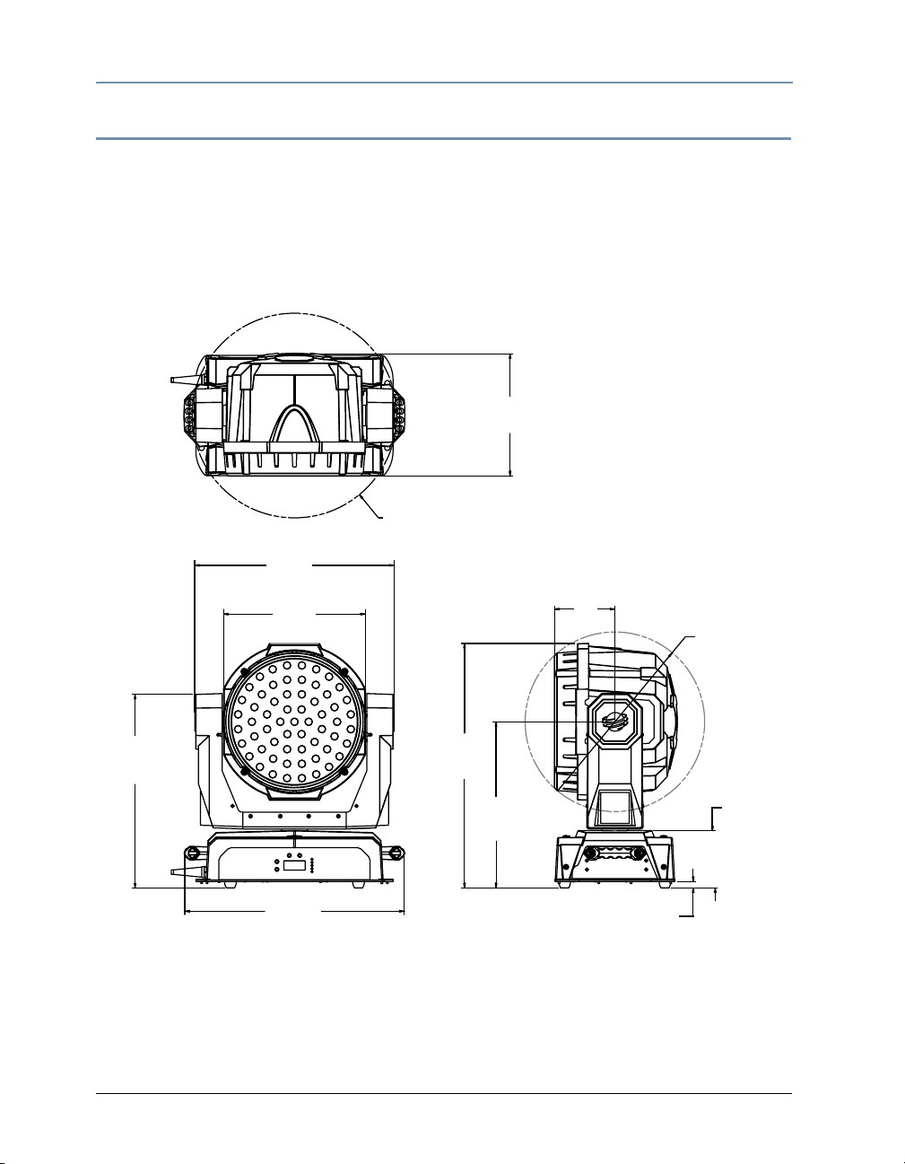
Mechanical Specifications
Fixture Dimensions: 540 mm x 300 mm x 601 mm (21.3 in x 11.8 in x 23.7 in)
Fixture Weight: 20.9 kg (46 lbs)
Roadcase Dimensions: 640 mm x 483 mm x 724 mm (24 in x 19 in x 28.5 in)
Shipping Weight (Roadcase + Fixture): 46.3 kg (102 lbs)
300 mm
11.8 in
503 mm
Ø
19.8 in
490 mm
19.3 in
349 mm
13.6 in
148 mm
5.9 in
441 mm
17.4 in
Ø
476 mm
18.7 in
540 mm
21.3 in
601 mm
23.7 in
408 mm
16.1 in
141 mm
5.6 in
16 mm
.6 in
Mounting Information
The StudioPix™ fixture can be truss mounted using suitable clamps with locking washers
through the center holes on the fixture’s base. Cheeseborough truss clamps and ½ inch nub/
bolt sets may be purchased separately. It can also stand upright on a stable surface.
4 StudioPix™ Pixelation Luminaire User Manual
Page 19

CHAPTER 1
Product Overview
Electrical/Light Source Specifications
Input ratings: 100-230 VAC; 50-60 Hz; 8-3.5A (800W)
LED Array: 61 3-watt RGB LEDs with homogenizing system
Output: 11,500 RGB lumens
Note: RGB lumens are calculated by comparing the combined energy levels
of StudioPix WRGBCMY to a theatrical metal halide color changing
fixture and creating a factor.
Beam angle: 45°
Field angle: 80°
Color mixing: RGB
Operation
Pan: 540°, Tilt: 210°
Control: DMX 512/RDM
Minimum distance from lighted object: 1 meter (3.9 ft.)
Compliances: CE, CSA, ETL
Content Management: Content and Software uploading to the fixture using Echo software via
a USB upload module or a Wholehog single USB DMX widget.
DMX connectors: 5-pin male and female XLR connectors
Environmental tolerances: Maximum ambient operating temperature 50° C (122° F);
maximum exterior surface temperature 70° C (158° F)
Software upgrades: Download operating software and Echo software from the High End
Systems website (www.highend.com)
StudioPix™ Pixelation Luminaire User Manual 5
Page 20

CHAPTER 1
Product Overview
6 StudioPix™ Pixelation Luminaire User Manual
Page 21

Chapter 2
Setup and Configuration
StudioPix™ fixture setup includes mounting, connecting to power and DMX
linking and configuration.
Use the following steps to set up and configure your StudioPix™ fixture:
1. Unpack the fixture.
2. Install power cord cap for your location.
3. Mount the fixture upright or suspended from a standard truss.
4. Connect the fixture to a DMX controller via DMX cabling.
5. Connect the fixture to power.
6. Configure the fixture for DMX control.
Unpacking the Fixture
The StudioPix™ fixture is transported in a shipping box or road case specifically designed to
protect the product during transport. When unpacking, inspect the fixture for physical damage
®
to components. High End Systems
during transport. Return a product for repair in its shipping box or road case. Before sending
anything to the factory, call your High End Systems dealer/distributor for a Return Material
Authorization (RMA) number. The factory cannot accept any goods shipped without an RMA
number.
assumes no responsibility for products that are damaged
Installing a Power Cord Cap
The StudioPix™ fixture’s custom power cord ships without a power cord cap. Use the
information in this section to install the correct power cord cap for your location.
Because of the variety of power cord caps used worldwide, High End Systems, Inc. cannot make
specific recommendations for the power cord cap. Contact a local authority for the type of power
cord cap needed. When installing the power cord cap, note that the cores in the mains lead are
colored according to the following code:
• green and yellow = earth
• blue = neutral
• brown = live
StudioPix™ Pixelation Luminaire User Manual 7
Page 22
CHAPTER 2
Setup and Configuration
Installing a Line Cord Cap - U.K. Only
In the United Kingdom, core colours in the mains lead of this equipment may not correspond
with the colored markings identifying the terminals in the fixture’s plug. In that case, install a
line cord cap according to the following code:
• Connect the green and yellow core to the plug terminal marked with the letter “E,” or by the
earth symbol
• Connect the blue core to the terminal marked with the letter “N” or coloured black.
• Connect the brown core to the terminal marked with the letter “L” or coloured red.
or coloured green, or green and yellow.
WARNING:
Class 1 equipment - This equipment must be earthed.
Vatic Fitter Heads Information - Danmark
Advarsel: Beskyttelse mod elektrisk chock.
Vigtigt!
Lederne med gul/groen isolation maa kun tilsluttes en klemme maerket
eller
Mounting the Fixture
You can mount your StudioPix™ fixture suspended from a support system (such as a truss) or
freestanding on its base.
WARNING!
Equipment suitable for dry locations only. Do not expose this
equipment to rain or moisture.
CAUTION!
Always use a secondary safety cable when mounting this fixture.
This fixture must be installed and operated by trained personnel only.
Maintain a minimum focus distance of 1 meter from a lighted object.
1 m
Note: Due to the wide variety of possible lighting designs, High End
Systems cannot make specific mounting recommendations. Consider
the following procedure as a suggested guideline only.
Mounting the Fixture Upright
CAUTION!
Do not mount the fixture upright without the four rubber feet attached.
To mount the fixture upright, place the fixture on a sturdy, stable non-flammable surface that
will support more than the
above floor height, use safety cables to secure the fixture to the surface.
8 StudioPix™ Pixelation Luminaire User Manual
20.9 kg (46 lb) weight of the StudioPix™ fixture. If the surface is
Page 23
Setup and Configuration
CHAPTER 2
Truss Mounting
If you are mounting the fixture(s) on a truss or another type of support, verify that the truss or
support will handle the weight of all the devices you are mounting.
Safety Cable
High End Systems strongly recommends that you use a safety cable when mounting any fixture.
You must supply your own safety cable and verify that the cable is capable of supporting the
weight of the fixture. You can order galvanized safety cables from your High End Systems
dealer/distributor (see
Clamp
You must supply your own clamps and verify the clamp is capable of supporting the weight of
the fixture. You can order deluxe C-clamps for a two-inch truss from your High End Systems
dealer/distributor (see
Mounting Procedure
To mount StudioPix fixtures on a truss:
1. Disconnect power to the fixture. If the fixture has been operating, allow the fixture to cool
before handling.
2. Always stand on a firm, stable surface when mounting a fixture to its support. The fixture
should be at a height where you can comfortably work on it, and should either be resting on
a stable surface, or held securely.
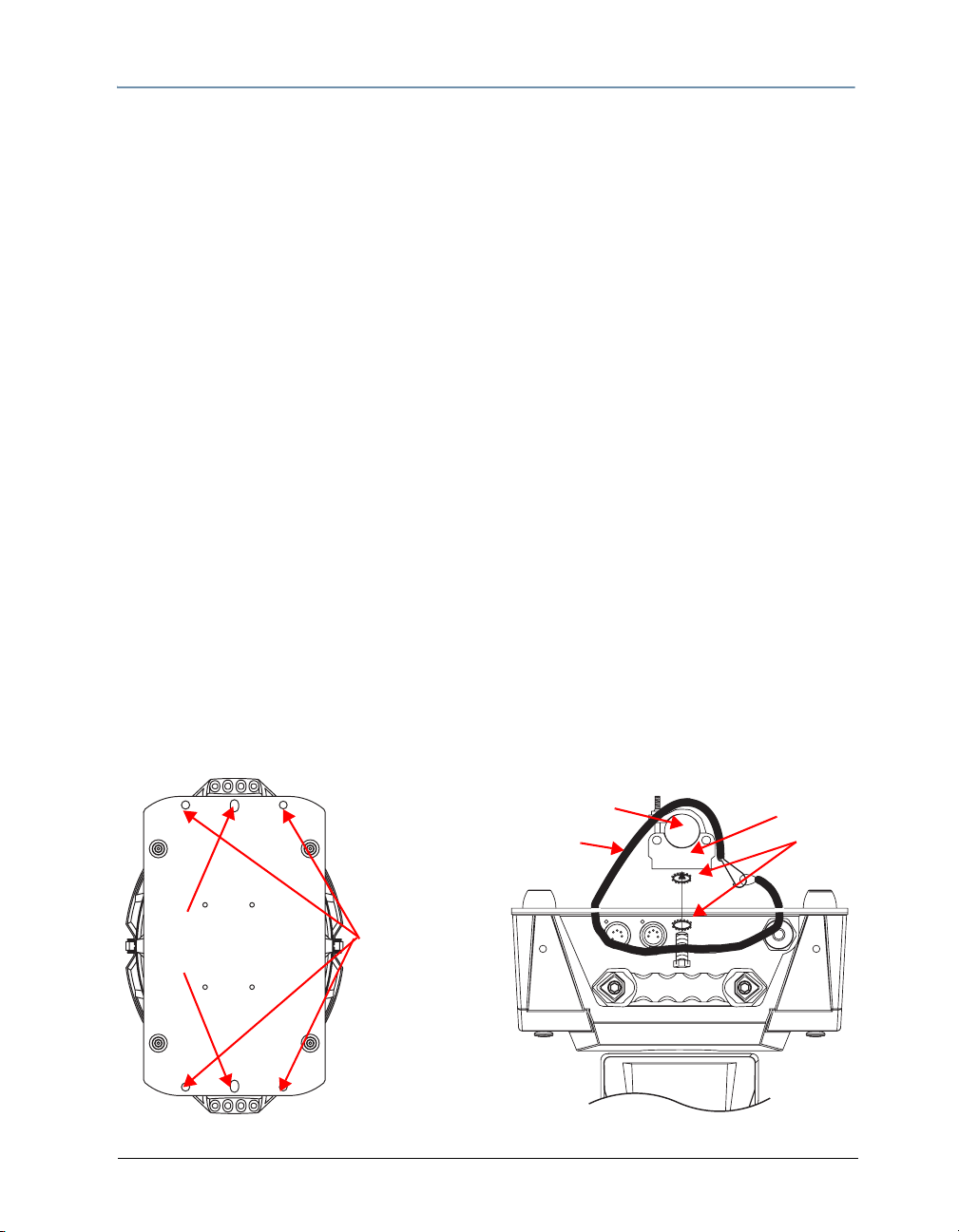
3. Attach suitable clamps through the center holes on the base of the fixture. Install two
locking washers per clamp when attaching the clamps to the fixture’s base.
4. Tighten the clamps firmly to the fixture’s base and to the support.
5. Loop one or more suitable safety cables around the support, through the side holes in the
fixture’s base, and around the fixture’s handles.
Related Products and Accessories on page 3).
Related Products and Accessories on page 3).
truss
safety
cable
Holes for
attaching
clamps
StudioPix™ Pixelation Luminaire User Manual 9
Holes for
securing
safety cables
clamp
locking
washers
Page 24
CHAPTER 2
Setup and Configuration
Linking StudioPix Fixtures
StudioPix™ fixtures operate on a standard DMX512 link controlled by a DMX console. The
number of fixtures on a link will be determined by the combined number of channels required by
all the fixtures. A StudioPix fixture using Standard protocol requires 70 channels on a DMX512
link. Attach the fixture to the link using data-grade cable and 5-pin XLR cable connectors.
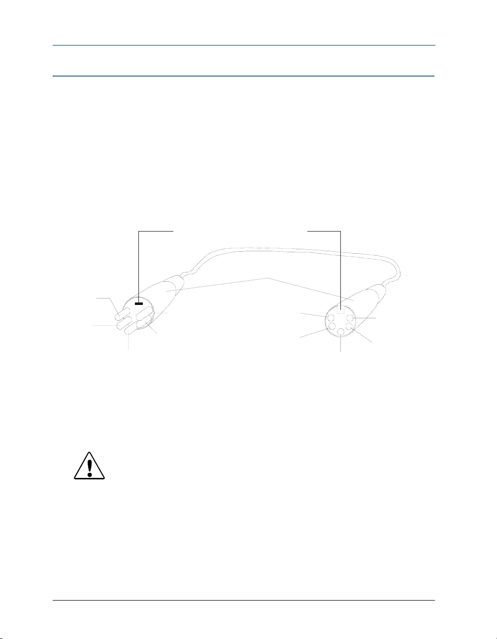
Cable Connectors
The StudioPix fixture accepts 5-pin XLR cable connectors. Cabling must have a male XLR
connector on one end of the cable and a female XLR connector on the other end.
Pin one is the common (cable shield), pin two is the data complement (negative), pin three is
the data true (positive). Pins four and five are not used, but they allow a secondary data link to
pass through the fixture.
Grounding lug (inside XLR shell)
XLR shell
Common
(cable shield)
negative
(data
complement)
positive
(data true)
5
1
2
3
4
positive
(data true)*
negative
(dat a co mpl ement)*
positive
(data true)*
negative
(data
complement)*
5
1
4
2
3
positive
(data true)
Common
(cable shield)
negative
(data
complement)
Male XLR Connector
Female XLR Connector
*This data line is not used by the fixt ure, but allows data to pass through the fixture.
Test each cable with a voltage/ohm meter (VOM) to verify correct polarity and to make sure that
the negative and positive pins are not grounded or shorted to the shield or to each other.
CAUTION!
Do not connect anything to the ground lug on the XLR connectors. Do
not connect or allow contact between the common (cable shield) and
the fixture’s chassis ground. Grounding the common could cause a
ground loop and/or erratic behavior.
10 StudioPix™ Pixelation Luminaire User Manual
Page 25
Setup and Configuration
CHAPTER 2
Connecting to the Link
To link one or more fixtures to a DMX controller:
1. Connect the male XLR connector of a DMX Data cable to the controller’s DMX Data Out
connector.
2. Connect the Data cable’s female XLR connector to the Data In connector of the first (or
next) fixture on the DMX link.
3. Continue linking the remaining fixtures connecting a cable from the Data Out connector of
each fixture to the Data In connector of the next fixture on the link.
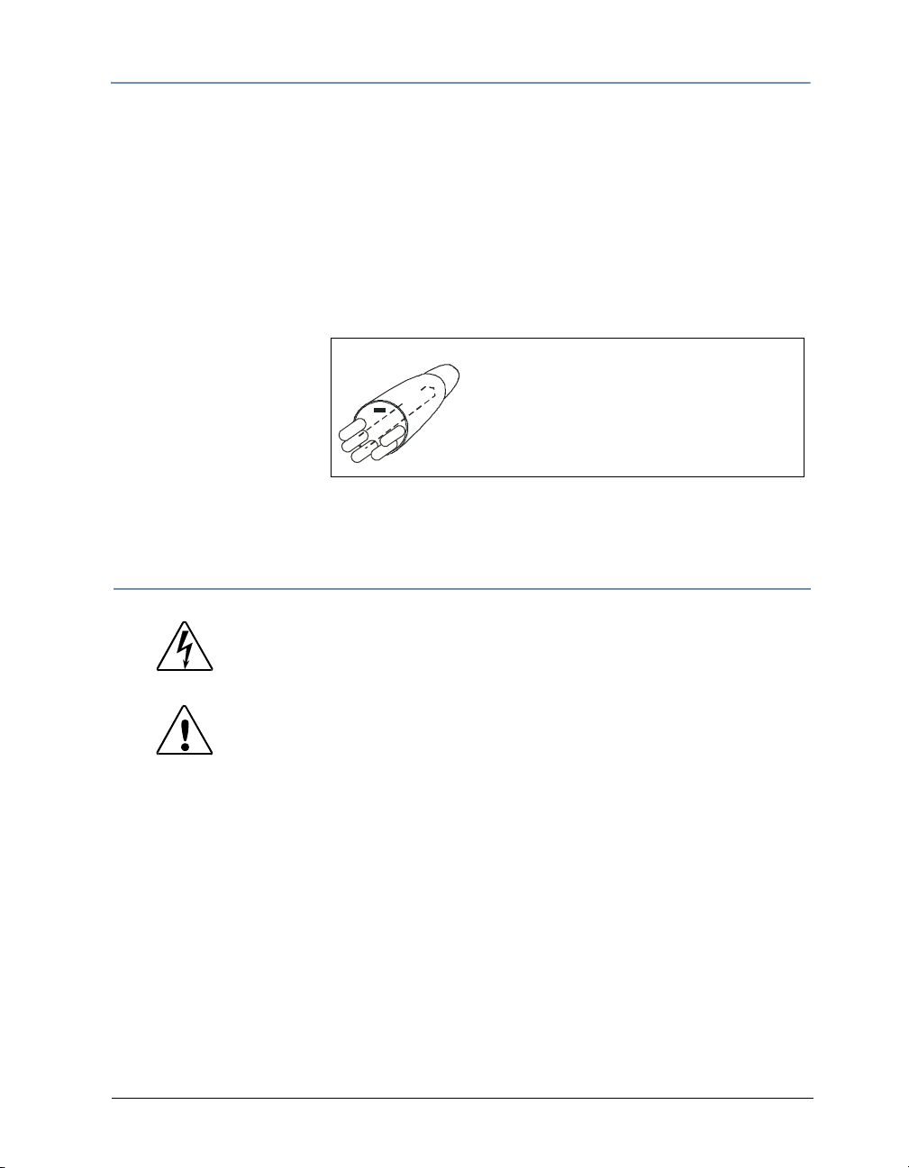
4. Terminate the link by
installing a 120 ohm,
1/4 watt (minimum)
terminator in the
fixture’s
Data Out
(female) cable
1
5
2
4
3
To construct a terminator:
1
2. Solder a 120 ohm resistor, minimum of
1. Disassemble a male 5-pin XLR connector.
0
2
1/4 watt, between Pin 2 and Pin 3.
3. Reassemble the XLR connector.
connector in the last
fixture on each DMX link. A terminator on the last fixture of the link prevents data
reflection, which can corrupt the data communication on the link.
Powering On the Fixture
WARNING:
This equipment is designed for connection to a branch circuit
having a maximum overload protection of 20 A.
CAUTION:
Do not power on the fixture until verifying that the line cord
cap is suitable for the power source in your location. For more
information, see
To power on the StudioPix fixture, simply connect it to a 100-230 V AC power source.
Once the StudioPix fixture is connected to a power source, it automatically begins a homing
procedure to verify the major functions of the fixture.
Installing a Power Cord Cap on page 7.
StudioPix™ Pixelation Luminaire User Manual 11
Page 26
CHAPTER 2
Setup and Configuration
Setting the DMX Start Channel
Each StudioPix fixture requires a block of consecutive channels on a 512-Channel DMX link. The
number of channels depends on the Protocol you are using.
To set the Start Channel on an StudioPix Fixture:
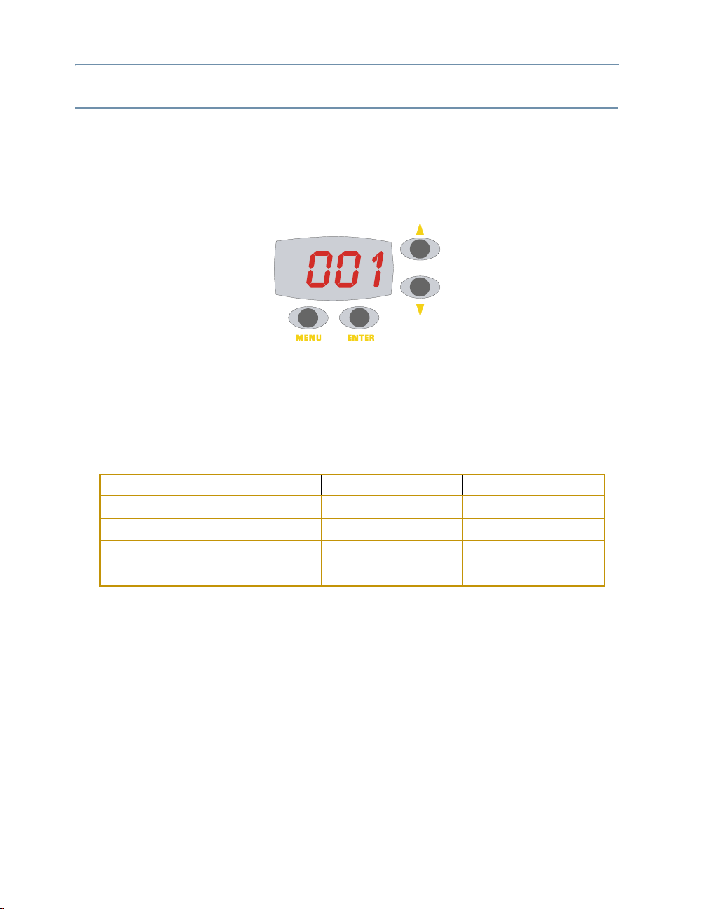
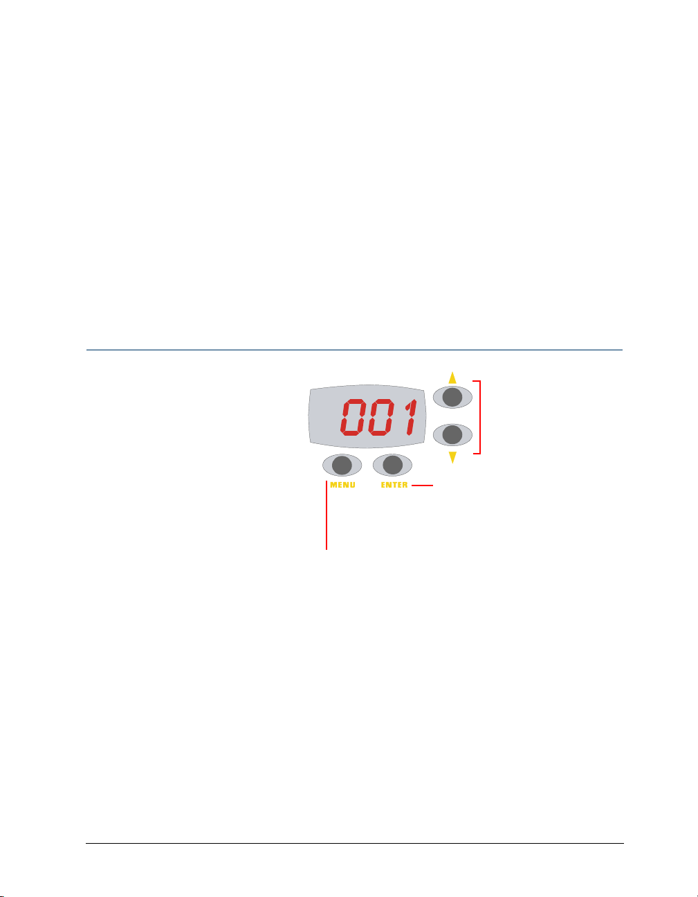
1. Access the fixture’s menu system via the dot matrix display on the fixture’s front panel. For
a detailed description of the menu system, see Chapter 3: The Menu System on page 15.
UP and DOWN arrows
scroll to an option or a value
MENU button unlocks the menu
and backs through menu levels
2. To unlock the menu, press and hold the Menu button until AddR appears on the LED
display. Press the Enter button to select.
3. The display will show the start channel currently assigned to the fixture.
4. Use the Up and Down arrow buttons to select a new DMX start channel. The display will
flash a new option ready for selection.
StudioPix™ Protocol Mode DMX Channel Range Last Valid Start Channel
Standard Protocol 70 442
RGB Reduced Protocol 12 501
Pixel Mapping Protocol 192 321
Extended Protocol 253 260
5. Press the Enter button to store the new DMX Start channel. The display will stop flashing
when a new option is entered.
When setting the Start channel on a fixture, remember:
• A fixture’s physical location on the link does not have to coincide with the order of channel
range assignments in the link.
• The fixture’s channel range must not overlap any other device’s channel range on the link.
When two devices on the same DMX link have overlapping channel ranges, one or both
devices will be disabled or behave erratically. The single exception would be if two or more
fixtures need to respond to controller commands in exactly the same way. In that case,
those fixtures must be the same type and must share the entire channel range.
ENTER button selects an
option or a menu value
12 StudioPix™ Pixelation Luminaire User Manual
Page 27

Setup and Configuration
CHAPTER 2
Shutting Down the Fixture
A DMX controller can shut down the fixture remotely with the Shutdown option in the Control
Channel or you can simply disconnect from power. The StudioPix fixture automatically shuts
down in the event of DMX data loss longer than five minutes.
StudioPix™ Pixelation Luminaire User Manual 13
Page 28

CHAPTER 2
Setup and Configuration
14 StudioPix™ Pixelation Luminaire User Manual
Page 29
Chapter 3
The Menu System
You can use the fixture’s onboard menu system to configure and test the
StudioPix fixture.
The onboard StudioPix menu system allows you to:
• Assign a DMX start channel.
• Access fixture options such as homing the fixture, viewing fixture status, and performing
self tests.
• View all DMX values on the link.
Navigating the Menu System
Access the menu system via the four
menu navigation buttons on the
fixture’s front panel.
The alphanumeric LED display shows
the menu items you select from the
menu map. When accessing fixture
options, the display will flash when a
new option is selected (by pressing
the <Up> or <Down> arrow buttons)
and stops flashing when a new option
is stored (by pressing the <Enter>
button).
Use the <Enter> button to select
and store a menu or option
Use the <Menu> button to
access the menu and return
to previous menu or option
Use <UP> and <Down>
arrow buttons to scroll
through menus
and options
To access the menu system: press and hold the <Menu> button until AddR appears on the
display. The menu system is protected against inadvertent menu changes by requiring the
<Menu> button to be held for a few seconds before allowing entry to the menu system.
To return to the previous option or menu without changing the value: press the
<Menu> button.
StudioPix™ Pixelation Luminaire User Manual 15
Page 30

CHAPTER 3
The Menu System
StudioPix Menu Map
Level 1 Level 2 Level 3 Description
ADDR Cxxx Change the existing DMX start channel
FACT
DSPL
P/IN
SET
T/IN
SWAP
DLOS
MODE PROT
HOME HOLD Homes the fixture
TEST
INFO
SELF
VER #### Displays the
TEMP
F/HR #### Displays current number of fixture hours
DMX 1-512 Displays the DMX data for the selected DMX channel
UNIQ Displays the fixture’s unique ID number
ON Sets factory defaults on
OFF Sets factory defaults off
ON Sets the LED display on
OFF Sets the LED display off
ON Sets pan invert on
OFF Sets pan invert off
ON Sets tilt invert on
OFF Sets tilt invert off
ON Sets pan/tilt swap on
OFF Sets pan/tilt swap off
LONG Keeps LED state until shutdown after DMX data is lost
SHRT Turns LEDs off one second after DMX data is lost
STD Selects Standard protocol
ENH Selects Enhanced protocol
PIX Selects Pixel Mapping protocol
RGB Selects RGB protocol
PAN Moves the head through the full pan range
TILT Moves the head through the full tilt range
RED Turns all LEDs red
GRN Turns all LEDs green
BLUE Turns all LEDs blue
PIX Turns each individual LED on
BASE Displays electronic housing internal temperature
HEAD Displays the head internal temperature
16 StudioPix™ Pixelation Luminaire User Manual
Page 31

CHAPTER 3
The Menu System
StudioPix Menu Options
The sections below explain how to access the fixture options shown in the fixture’s menu map.
This manual uses the following conventions in the descriptions for menus and menu navigation
buttons:
Example Meaning
<Button>
Menu Option
Address Menu (AddR)
The DMX start channel identifies each fixture on a DMX link. You must assign a DMX start
channel to each fixture on the link.
The Address menu allows you to change the DMX start channel that is currently assigned to the
fixture. Be sure you do not overlap fixture channel ranges when changing the DMX start
channel. For more information, see
To change the DMX start channel:
1. Press and hold <Menu> until AddR appears on the LED display. Press <Enter> to select.
2. Select a new DMX start channel. The LED display flashes when a new start channel is
selected.
3. Press <Enter> to accept the new DMX start channel. The LED display stops flashing when a
new option is entered. If you do not press <Enter>, the new option you selected is not
stored.
Press the appropriate LED display navigation button on the fixture. For example, the
<Enter> button on the LED display panel.
Italics are used to indicate the appropriate menu selection you should choose from the
on-board menu system. For example, the AddR menu option.
Determining a DMX Start Channel on page 24.
Set Menu (SET)
Setting Factory Defaults (FACT)
When you set this menu item on, all factory options return to their default settings. StudioPix
fixtures are shipped from the factory with the following default option settings:
pan/tilt swap = off
tilt invert = off
The factory default menu option displays On if all the factory options are at the factory default
settings. If any of the items listed above are not at the factory default setting, the display reads
OFF. Selecting the OFF option will have no effect. To restore the factory default setting:
1. Press and hold <Menu> until AddR appears on the LED display.
2. Scroll to the SET menu. Press <Enter> to select.
3. Scroll to the FACT menu (this will be the first menu displayed). Press <Enter>.
4. Scroll to ON to restore the factory option defaults.
5. Press <Enter> to store.
StudioPix™ Pixelation Luminaire User Manual 17
pan invert = off
LED display = on and bright
LED off with DMX data loss = short
Page 32

CHAPTER 3
The Menu System
Changing the Display Output (DSPL)
You can manually turn the fixture’s alphanumeric LED display on or off. If you want to remotely
change the display output (using a DMX console), see
To turn the display off:
1. Press and hold <Menu> until AddR appears on the LED display.
2. Scroll to the SET menu. Press <Enter> to select.
3. Scroll to the DSPL menu. Press <Enter> to select.
4. Scroll to ON to set the LED display to normal intensity.
5. Press <Enter> to store.
Control Function Options on page 34.
Inverting Pan (P/IN)
This menu item inverts the direction of the pan motor, to allow fixtures mounted opposite each
other horizontally to respond to pan movement commands in the same direction.
To invert the fixture’s pan motion:
1. Press and hold <Menu> until AddR appears on the LED display.
2. Scroll to the SET menu. Press <Enter> to select.
3. Scroll to the P/IN menu. Press <Enter> to select.
4. Scroll to ON to invert the fixture’s pan motion, or OFF to return the fixture’s pan motion to
normal orientation.
5. Press <Enter> to store.
Inverting Tilt (T/IN)
This menu item inverts the direction of the tilt motor, to allow fixtures mounted opposite each
other vertically to respond to tilt movement commands in the same direction.
To invert the fixture’s tilt motion:
1. Press and hold <Menu> until AddR appears on the LED display.
2. Scroll to the SET menu. Press <Enter> to select.
3. Scroll to the T/IN menu. Press <Enter> to select.
4. Scroll to ON to invert the fixture’s tilt motion, or OFF to return the fixture’s tilt motion to
normal orientation.
5. Press <Enter> to store.
18 StudioPix™ Pixelation Luminaire User Manual
Page 33

CHAPTER 3
The Menu System
Swapping Pan and Tilt (SWAP)
This menu option swaps the pan motor and tilt motor operation to allow fixtures hung
perpendicular to each other to respond to pan and tilt movement commands in the same
direction. To swap pan and tilt motion:
1. Press and hold <Menu> until AddR appears on the LED display.
2. Scroll to the SET menu. Press <Enter> to select.
3. Scroll to the SWAP menu. Press <Enter> to select.
4. Scroll to ON to swap the fixture’s pan and tilt motion, or OFF to return the fixture’s pan and
tilt motion to normal orientation.
5. Press <Enter> to store.
Data Loss (DLOS)
Use this menu item to determine how the fixture will react in the event of DMX data loss by
turning off the LED’s upon Data Loss or keeping the LEDs on until shut down.
To select a data loss option:
1. Press and hold <Menu> until AddR appears on the LED display.
2. Scroll to the SET menu. Press <Enter> to select.
3. Scroll to the dLOS menu. Press <Enter> to select.
4. Scroll to LONG to turn the LEDs off only when the fixture is shut down, or SHRT to turn off
the LEDs one second after data loss.
5. Press <Enter> to store.
Mode Menu (MODE)
Setting Protocol Option (PROT)
Use this menu item to change the current protocol option:
1. Press and hold <Menu> until AddR appears on the LED display.
2. Scroll to the MODE menu. Press <Enter> to select.
3. Scroll to the PROT menu (this will be the first option displayed). Press <Enter>.
4. Scroll to STD for Standard protocol, EHN for Enhanced protocol, PIX for Pixel Mapping
protocol or RGB for wash light functionality.
5. Press <Enter> to store.
StudioPix™ Pixelation Luminaire User Manual 19
Page 34

CHAPTER 3
The Menu System
Test Menu (TEST)
The Test menu allows you to manually home the fixture and perform fixture self tests to
determine the origin of mechanical problems.
Homing the Fixture (HOME)
This menu item allows you to manually home the fixture. To remotely home the fixture using a
DMX console, see
1. Press and hold <Menu> until AddR appears on the LED display.
2. Scroll to the TEST menu. Press <Enter> to select.
3. Scroll to the HOME option (this will be the first option displayed).
4. Press <Enter> to store.
Performing Self Tests (SELF)
The following self tests are available:
Construct Self-Test Description
ALL Performs all of the self tests listed below
PAN Moves the head through the full pan range
TILT Moves the head through the full tilt range
RED Turns all LEDs red
GRN Turns all LEDs green
BLUE Turns all LEDs blue
PIX Turns each individual LED on
Control Function Options on page 34. To manually home the fixture:
To start a self test process:
1. Press and hold <Menu> until AddR appears on the LED display.
2. Scroll to the TEST menu. Press <Enter> to select.
3. Scroll to the SELF menu. Press <Enter> to select.
4. Scroll to the desired option (listed above).
5. Press <Enter> to start the test. The fixture will perform the selected self test.
6. Press <Menu> to exit the test.
20 StudioPix™ Pixelation Luminaire User Manual
Page 35

CHAPTER 3
The Menu System
Information Menu (INFO)
The Information menu allows you to view current fixture information such as internal
temperature, fixture hours, software version, and DMX data for any other device on the link.
Viewing the Current Software Version (VER)
To view the current software version:
1. Press and hold <Menu> until AddR appears on the LED display.
2. Scroll to the INFO menu. Press <Enter> to select.
3. Scroll to the VER option.
4. Press <Enter>. The LED will display the fixture’s current software version.
Viewing the Electronic Housing Temperature (BASE)
This menu option allows you to view the current ambient temperature at the logic board inside
the fixture. To view the electronic housing temperature:
1. Press and hold <Menu> until AddR appears on the LED display.
2. Scroll to the INFO menu. Press <Enter> to select.
3. Scroll to the TEMP menu. Press <Enter> to select.
4. Scroll to the BASE option.
5. Press <Enter>. The LED will display the current internal temperature of the fixture’s logic
board in degrees centigrade.
Viewing the Current Fixture Head Temperature (HEAD)
This menu option lets you view the current ambient temperature inside the fixture head. To
view the head temperature:
1. Press and hold <Menu> until AddR appears on the LED display.
2. Scroll to the INFO menu. Press <Enter> to select.
3. Scroll to the TEMP menu. Press <Enter> to select.
4. Scroll to the HEAD option.
5. Press <Enter>. The LED will display the current internal temperature of the fixture’s logic
board in degrees centigrade.
Viewing the Current Fixture Hours (F/HR)
To view the number of hours the fixture has been on since this option was reset:
1. Press and hold <Menu> until AddR appears on the LED display.
2. Scroll to the INFO menu. Press <Enter> to select.
3. Scroll to the F/HR option.
4. Press <Enter>. The LED will display the number of hours the fixture has been on.
StudioPix™ Pixelation Luminaire User Manual 21
Page 36

CHAPTER 3
The Menu System
Viewing DMX Data for the Link (DATA)
This procedure allows you to use a StudioPix fixture to view DMX channel values all devices on
the DMX link. Use this menu option to:
• Checking current DMX values on this fixture
• Test devices that do not have built-in DMX diagnostics
• Check fixtures that are physically inconvenient to monitor directly
If you experience a problem with a device on the link, use this menu to select a DMX channel in
the device’s channel range and view its DMX value. After noting the value of the channel you
selected, use your DMX console to change that channel’s value.
If the value of the DMX channel you selected does not change, there may be a problem with the
DMX cable or your transmitting device (i.e. DMX console).
If the DMX channel value changes, but the device does not respond, the device may be faulty.
Consult the documentation provided with that device for more information.
To view DMX data for another device on the DMX link:
1. Press and hold <Menu> until AddR appears on the LED display.
2. Scroll to the INFO menu. Press <Enter> to select.
3. Scroll to the dMX menu. Press <Enter> to select.
4. Scroll to the desired DMX channel (001 – 512). Channel numbers will flash.
5. Press <Enter> The DMX value for the selected channel will be displayed.
Viewing the Unique Fixture ID (UNIQ)
To view the fixture’s identification number:
1. Press and hold <Menu> until AddR appears on the LED display.
2. Scroll to the INFO menu. Press <Enter> to select.
3. Scroll to the UNIQ option.
4. Press <Enter>. The LED will display the fixture’s unique ID number.
22 StudioPix™ Pixelation Luminaire User Manual
Page 37

Chapter 4
DMX Programming Basics and Quick Start
If you are new to DMX programing, this chapter will give you a brief overview
on programming SHOWPIX™ and StudioPix™ fixtures followed by a example
using a Wholehog console to patch and display output.
DMX Programming Overview
DMX512 Links
A lighting console typically utilizes a protocol called DMX512 to communicate with automated
lighting fixtures and conventional dimmers. This protocol consists of 512 unique channels of
control per output link (universe). Typically a lighting fixture or device will use a channel for
each parameter’s function. Each channel consists of 256 values ranging from 0 to 255. The
lighting console is programmed to transmit a corresponding DMX value for the desired function
of each parameter. All DMX values are stored within in the lighting console, and typically are
referred to as cues, scenes, or presets. A lighting console locates a device on the link by it’s
DMX Start Channel.
8-bit vs. 16-bit DMX Parameters
Most parameters of an automated light use one channel of DMX providing 256 values of control
(0-255). This is known as 8-bit DMX. Although most parameters use 8-bit DMX, several require
a more accurate range of values than can be provided with a single DMX channel.
By utilizing two DMX channels for a single parameter, 65535 values become available for
controlling and adjusting parameter functions. This is known as 16-bit DMX. You can adjust
16-bit DMX values in both coarse and fine increments. The first channel of the pair provides
coarse control changes of the DMX value in increments of 256. The second channel provides fine
control and changes of the DMX value in increments of 1.
Individual access of the two DMX channels used with 16-bit parameters varies by lighting
console. Most modern DMX consoles bind these two channels into a single 16-bit parameter to
accurately perform 16-bit crossfades. Consult your lighting console manual for further
information.
StudioPix™ Pixelation Luminaire User Manual 23
Page 38

CHAPTER 4
DMX Programming Basics and Quick Start
Determining a DMX Start Channel
The DMX Start Channel is the first channel of a device’s channel range on a DMX link. There are
512 available channels on each DMX universe divided among all the devices in a particular
universe. A device must have a unique DMX Start Channel number in order to respond
independently to controller commands.
To determine each device’s DMX Start Channel, identify the footprint of every device on the
universe. The device’s footprint is the number of consecutive DMX channels a device requires
and is determined by the channels in the fixture’s protocol. The fixture’s DMX channel range
must not overlap any other device’s channel range on the link. When two devices on the same
DMX universe have overlapping channel ranges, one or both devices will be disabled or behave
erratically.
Last Valid Start
Channel
Protocol
Mode
Standard
Protocol
RGB Reduced
Protocol
Pixel Mapping
Protocol
Extended
Protocol
Description
Full control of graphic engine with global
and two image layers
Washlight control only with red, green,
blue, intensity, and strobe controls
Individual RGB control of LEDs plus
master intensity, and strobe
Full control of graphic engine with
Individual RGB control of LEDs available
for additional media input
DMX Channel Range
SHOWPIX StudioPix SHOWPIX StudioPix
70 70 442 442
12 12 501 501
390 192 123 321
451 253 62 260
Select the protocol level in the fixture’s onboard menu system. The tables on the following
pages list the parameters included in each protocol mode.
24 StudioPix™ Pixelation Luminaire User Manual
Page 39

DMX Programming Basics and Quick Start
CHAPTER 4
SHOWPIX and StudioPix Protocol Modes
You can choose from four protocol modes for variable programming styles. High End Systems is
currently distributing the detailed DMX protocols as requested to console and visualizer
manufacturers in an attempt to ensure that the fixture libraries are created in a method that
allows optimum control of the fixture. The charts below provide only an outline of each
channel's function. If your console does not provide a library for SHOWPIX and StudioPix
fixtures, please contact the console manufacturer to have one created.
Standard Protocol
Standard protocol provides motion control plus full graphics engine control of images, colors,
and effects for the two separate image files and the composite image they form. For details on
specific DMX parameters, see Chapters
Standard Protocol Table for SHOWPIX and StudioPix
Motion Control Global Control Image Control
Chan
#
1
2 9
3
4 11
5
6
7
Description
Pan
Tilt
Mspeed
Macro
Control Function
Chan
#
8
Strobe
Dim
10
Color Function
Red
12 29 52
13
Green
14 31 54
15
Blue
16 33 56
17
Scale
18
Global Rotate
19
Dampening
20
Global Transition Mode
21
Global Transition
22
Effect Function
23
Effect Modifier 1
24
Effect Modifier 2
5–10.
Description
Image 1
Chan #
25 48
26 49
27 50
28 51
30 53
32 55
34 57
35 58
36 59
37 60
38 61
39 62
40 63
41 64
40 65
43 66
44 67
45 69
46 60
47 70
Image 2
Chan #
Description
Media Folder
Media file
Frame
Play mode
Play speed
Scale
Rotate
X Position
Y Position
Color Function
Red
Green
Blue
Transparent Color
Background Color
Image Transition Mode
Transition Speed
Effect Function
Effect Modifier 1
Effect Modifier 2
StudioPix™ Pixelation Luminaire User Manual 25
Page 40

CHAPTER 4
DMX Programming Basics and Quick Start
RGB Reduced Protocol
This protocol choice lets you utilize SHOWPIX and StudioPix fixtures as powerful wide angle
washlights by providing control of motion and color mixing only.
Note: Reduced protocol provides 8-bit color control instead of the 16-bit
color mixing used in the Standard Protocol
RGB Reduced Protocol Table for SHOWPIX and StudioPix
Chan # Description
1
Pan
2
3
Tilt
4
5 Mspeed
6 Macro
7 Control Function
8 Strobe
9 Dim
10 Red
11 Green
12 Blue
26 StudioPix™ Pixelation Luminaire User Manual
Page 41

DMX Programming Basics and Quick Start
CHAPTER 4
Pixel Mapping Protocol
Pixel Mapping protocol allows you to individually control RGB color each of the LEDs with your
DMX desk or a third party pixel mapping protocol. LEDs are identified by the protocol according
to the array maps in the following sections.
SHOWPIX Pixel Mapping Table
A SHOWPIX array consists of 127 LEDs with each acting as a single pixel of an image. The
example to the right designates the position of the channels assigned to LEDs in the Pixel
Mapping Protocol. The following table shows the color assignment for the LEDs
The following table shows the color assignment for the LEDs. The image below labels each LED
position on the array.
Fixture Control LED Control
Chan # Description Chan # Description
1
Pan
211
3
Tilt
4 . . .
Mspeed
5
Macro
6
Control Function
7
8
Strobe
9
Dim
Red
10
LED 1
Adjust three DMX channels for
RGB control with values from 0 =
no color to 255 = full saturation.
LED 127
12
. . .
. . .
388
389
390
Green
Blue
Red
Green
Blue
Red
Green
Blue
Channel 10 = Red
Channel 11 = Green
Channel 12 = Blue
4
5
40
48
15
6
41
7
42
71
43
72
44
73
45
74
46
12
47
13
14
8
9
10
11
28
27
Channel 247 = Red
Channel 248 = Green
Channel 249 = Blue
1
36
35
34
33
32
31
62
30
61
29
60
59
58
26
57
25
56
24
23
64
63
88
87
106
86
105
85
84
83
118
104
117
103
102
82
81
55
54
22
21
65
89
107
119
116
101
80
53
20
108 91
120 109
126
125
124
115
100
66 37
90 67
127
79
52
19
121
123
114
2
3
38
39
68
69
92
110
122
113
98
99
77
78
50
51
17
18
70
93
94
111
95
112
96
97
75
76
49
16
StudioPix™ Pixelation Luminaire User Manual 27
Page 42

CHAPTER 4
DMX Programming Basics and Quick Start
StudioPix Pixel Mapping Table
A StudioPix array consists of 61 LEDs with each acting as a single pixel of an image. The
following table shows the color assignment for the LEDs. The image below labels each LED
position on the array.
Fixture Control LED Control
Chan # Description Chan # Description
1
Pan
211
3
Tilt
4 . . .
Mspeed
5
Macro
6
Control Function
7
8
Strobe
9
Dim
10
12
. . .
. . .
190
191
192
Red
Green
Blue
Red
Green
Blue
Red
Green
Blue
LED 1
Adjust three DMX channels for
RGB control with values from 0 =
no color to 255 = full saturation.
LED 61
Channel 157 = Red
Channel 158 = Green
Channel 159 = Blue
24 1
23
22
21
40
20
39
19
38
18
37
17
36
16
15
42 25
41
54 43
53
60
53
59
61
52
58
50
49
35
34
14
13
2
3
26
44
55
56
57
47
48
32
33
11
12
4
27
5
28
45
46
31
10
6
29
7
30
8
9
Channel 10 = Red
Channel 11 = Green
Channel 12 = Blue
28 StudioPix™ Pixelation Luminaire User Manual
Page 43

DMX Programming Basics and Quick Start
CHAPTER 4
Extended Protocol
Use the Extended Protocol when you want all the movement, global and image control of
Standard Protocol plus individual RGB control of individual LEDs. When using Pixel mapping
channels in Extended protocol, note the following:
• The Folder channel for a selected image must equal 255 to allow pixel mapping input from
on the selected image layer.
• Transparent Color and Background Color will be inactive since they require an image file be
selected. Pixel mapping looks only at raw pixel values, not a file.
SHOWPIX and StudioPix Fixtures Extended Protocol Table
Motion Control Image Control LED Control
Chan
#
1
3
4 28 51 Play mode 74
5 Mspeed 29 52 Play speed 75
6 Macro 30 53 Scale 76
7 Control Function 31 54 Rotate 77
Chan
#
8 Strobe 34 57 Color Function 80
10 Color Function 36 59 82
11
13
14 40 63 86
16 40 65 Background Color 88
17 Scale 43 66 Image Transition Mode 89
19 Dampening 45 69 Effect Function 91
20 Global Transition Mode 46 60 Effect Modifier 1 . . . Note: Continue
21 Global Transition 47 70 Effect Modifier 2 . . .
22 Effect Function . . .
23 Effect Modifier 1 251
24 Effect Modifier 2 252
Description
Pan
Tilt
Global Control
Description
Red
Green
Blue
Image 1
Chan #
Image 2
Chan #
25 48 Media Folder 71
27 50 Frame 73
32 55 X Position 78
33 56 Y Position 79
37 60
39 62
41 64 Transparent Color 87
Description
Red
Green
Blue
Chan
#
RGB LED 1 2 26 49 Media file 72
RGB LED 2
RGB LED 3
RGB LED 49 Dim 35 58
81
83
RGB LED 512 38 61 84
85
RGB LED 615
RGB LED 718 Global Rotate 44 67 Transition Speed 90
assigning three
channels for RGB
control to each LED.
LED 61 (last three
channels for StudioPix
fixture)
253
449
LED 127 (last three
channels for
450
SHOWPIX fixture)
451
Description
StudioPix™ Pixelation Luminaire User Manual 29
Page 44

CHAPTER 4
DMX Programming Basics and Quick Start
Lighting Console Tips
Lighting consoles differ in many aspects and it is important to understand how your console
operates with SHOWPIX and StudioPix fixtures.
Fixture Libraries:
Many sophisticated lighting consoles utilize pre-made fixture libraries. A fixture library consists
of profiles for various types of lighting fixtures and devices. Each profile corresponds to the
fixture’s DMX protocol and allows for ease of programming. Depending upon the manufacturer
of your lighting console, some parameters might have different labels for parameter names and
functions than are listed within this manual. Consult your lighting console manual for additional
information.
Note: The suggested default DMX values given for each parameter in
chapters describing fixture, color, image and global DMX control are
recommended to build libraries that provide the easiest and most
reliable content selection, and output. They are the default values built
into the Wholehog libraries for High End Systems consoles.
Patching SHOWPIX and StudioPix Fixtures Using the Standard Protocol
SHOWPIX and StudioPix fixtures using the Standard protocol are patched as three different
“fixture types” in the Wholehog library systems. This allows for ease of programming as well as
the ability to adjust quickly for any of the various DMX protocol options. The Standard fixture
type controls yoke movement and global graphic engine functions such as intensity, color,
transitions, etc. The Image fixture type controls each image layer functions such as media,
color, position, rotation and effects. Because SHOWPIX and StudioPix use two image layers, two
Image fixture types are needed to control a single fixture.
The best way to organize your patching is to assign user numbers for these items. Patch the
Standard fixture type and then the two Image fixtures types. For example, set up user numbers
1-3 that correspond to the fixture number 1, where user number 1 is the Standard, and user
numbers 2 and 3 are Image fixture types.
Patching SHOWPIX and StudioPix Fixtures in Other Protocol Modes
For patching Wholehog, use the following:
Reduced Mode
• 1 SHOWPIX or StudioPix Reduced
Pixel Mapping Mode
• 1 SHOWPIX or StudioPix Pixel mapping
• 127 generic RGB LED for SHOWPIX fixtures or 61 generic RGB LED for StudioPix fixtures
30 StudioPix™ Pixelation Luminaire User Manual
Page 45

DMX Programming Basics and Quick Start
CHAPTER 4
Enhanced Mode
• 1 SHOWPIX or StudioPix Standard
• 2 SHOWPIX or StudioPix Image
• 127 generic RGB LED for SHOWPIX fixtures or 61 generic RGB LED for StudioPix fixtures
DMX Output Displays
Although all lighting consoles output the same 512 DMX channels per universe, the on-screen
labeling often differs. Parameter functions are displayed in either alpha-numeric descriptions
(strobe 1), percentage (0-100%) or decimal (0-255 for 8-bit and 0-65535 for 16-bit). Consult
your lighting console manual for further information.
Wholehog Programming Notes
Play Modes (Intensity)
Using the Image fixture type, press the Mode button to view the play mode options. By default
all modes trigger normally. If available per the SHOWPIX or StudioPix DMX protocol, you can
select “Media Trigger Intensity” to change to the Play Modes that trigger when Intensity is
greater than zero. When using one of these modes, the media will pause when the intensity is
at zero and plan when the intensity is greater than zero. To restore to normal triggering, select
“Media Trigger Normal”.
CMY
The Standard and Image fixture types both contain CMY controls for the Color Function modifier
channels. For some color function options, the CMY parameters will not adjust color, but will
adjust the color function per the SHOWPIX or StudioPix protocol.
The Wholehog libraries default to CMY mode for control of SHOWPIX or StudioPix. This allows
for use of standard color mixing, global palettes, and the color and gel pickers.
Custom Wheel Sets
You can import a custom preference file to your Wholehog show file to rearrange the wheelset
for easier accessibility to the parameters of SHOWPIX or StudioPix. The wheelset can be found
on Wholehog consoles in the Preferences folder or downloaded from:
http://www.flyingpig.com/support/hog3/downloads/library/index.shtml.
StudioPix™ Pixelation Luminaire User Manual 31
Page 46

CHAPTER 4
DMX Programming Basics and Quick Start
Quick Start with a Wholehog Console
After Setting up and Configuring the SHOWPIX or StudioPix fixture as outlined in Chapter 2, use
the following steps to get to the point of displaying output.
Step 1: In the Fixture Schedule window of Wholehog software, Add one Standard and two
Image “fixtures” for each unit.
Step 2: Assign user numbers for these items. Set up user numbers 1-3 that correspond to
SHOWPIX or StudioPix unit number 1, where user number 1 is the Standard, 2 and 3 are Image
fixture types. Patch the Standard first and then the two Image fixture types.
32 StudioPix™ Pixelation Luminaire User Manual
Page 47

Chapter 5
Fixture Control
This chapter describes mechanical movement control for SHOWPIX™ and
StudioPix™ fixtures in all protocol modes.
Pan and Tilt
SHOWPIX fixtures have a 400° pan range and a 240° tilt range. StudioPix fixtures have a 540°
pan range and a 210° tilt range.
Two DMX channel s f o r Pan and two for Tilt provide 16-bit position adjustment to a fraction of a
degree.
MSpeed values can control the timing of pan and tilt motion for SHOWPIX and StudioPix
fixtures. To control Pan and Tilt movement timing via a DMX controller crossfading, leave the
Pan/Tilt MSpeed in it’s default Off setting.
Note: SHOWPIX and StudioPix fixtures use optical encoders for pan and tilt
to instantly correct the fixture’s position if the fixture is jarred from its
programmed position.
If a physical obstruction prevents the fixture from correcting its position, this
correction feature “times out” to prevent wear on the motors.
If the fixture’s position correction has timed out, remove the
obstruction and home the fixture to return it to normal operation.
MSpeed (Motor Speed)
The MSpeed parameter adjusts the time required for a motor to complete movement when
changing from one position to another. MSpeed provides a method for all motors to reach their
target position at the same time, even though each motor may have different distances to
travel. MSpeed movement is extremely smooth because the fixture controls movements
independent of DMX refresh rates.
MSpeed times vary from 0.15 seconds to 252.7 seconds. In general, allowing the console to
crossfade the pan and tilt values for a SHOWPIX fixture is acceptable. However, extremely slow
movements may require the use of Mspeed instead of console crossfades. For a listing of exact
MSpeed times, see
StudioPix™ Pixelation Luminaire User Manual 33
Appendix A: MSpeed Conversion Table on page 97.
Page 48

CHAPTER 5
Fixture Control
Macros
The Macro parameter controls Internal Effects™ macros. These are factory-programmed
sequences that allow you to quickly program complicated looks in one scene (cue). Each
Internal Effect™ macro modifies a specific set of parameters, while allowing user control of all
other parameters in the scene. The amplitude of the position macro movement is determined by
the Pan Coarse channel and Tilt Coarse channel, respectively. The MSpeed channel controls the
speed of the macros. You can choose from the following Macros:
• Pan sweep, small to large angle
• Tile Sweep, small to large angle
• Clockwise circle, small to large
• Counterclockwise circle, small to large
With the MSpeed set at the default value of DMX 0-4, an Internal Effects macro completes its
movement in approximately 2.5 seconds. This provides a pleasing look when the additional
variation given by using the MSpeed channel is not required. With the MSpeed set between DMX
5-255, Internal Effects macros complete movement at the selected MSpeed time (up to 25
seconds).
Control Function Options
The Control parameter remotely initiates various fixture operations.
Note: All of the following Control parameter settings (except for the Safe and
Outrig mode options), require that the Dim channel value equals zero.
DMX Value
(dec.)
0-9
20-28
40-48
60-68
120-130
131-140
34 StudioPix™ Pixelation Luminaire User Manual
Control
Option
Safe
Display Off
Display Bright
Home
Shutdown
Outrig Mode
Description
Disables all Control setting
Turns the Display off
Sets the Display to bright
Remotely homes all the motion functions of the fixture
Remotely deactivates the fixture. When a fixture is shut down, the
graphic engine stops, power to the motors is disabled, and the menu
display reads
fixturesIf a fixture is in shutdown mode, you must home the fixture to
bring it back into operation.
This option applies to SHOWPIX fixtures only. For more information,
see Chapter 2: Setup and Configuration in the SHOWPIX User
Manual. It insures uninterrupted movement of pan and tilt for fixtures
side mounted or in acute angular positions.
Because this is a DMX mode, it will not persist in the fixture.
SHUT DOWN in SHOWPIX fixtures or S/DN in StudioPix
Page 49

Chapter 6
Color Control
The Standard protocol modes for SHOWPIX and StudioPix fixtures provide
color mixing control for up to two image files and a composite image.
Other protocol modes provide washlight operation or individual LED color
mixing.
The type of color control depends on the protocol mode you select for the fixture:
• Standard protocol assigns two channels each for Red, Green, and Blue parameters to
provide 16-bit color mixing for each of the two images and the global composite image.
Several color mixing modes are available (see Color Function Parameter on page 36).
• Reduced protocol assigns three channels for 8-bit Red, Green, and Blue color mixing.
• Pixel Mapping protocol gives you precision color control of every “pixel” of the fixture
array with 8-bit color mixing for each LED.
• Extended protocol provides all the color control offered in Standard protocol plus individual
LED color mixing.
For a table of each protocol mode’s parameters, see SHOWPIX and StudioPix Protocol Modes on
page 25.
Color Parameters
Red, Green and Blue parameters let you control color mixing and in Standard and Extended
protocol, provide adjustment for various Color function options.
Default DMX Value = 0: No color (All protocol types)
In Standard and Extended protocol Red, Green, and Blue parameters adjust from no color at a
DMX value = 0 to full saturation at a DMX value = 65,535.
Note: To Control LEDs as a Single Color in Standard or Extended protocol
modes, set Folder and File and Color Function parameters to a DMX
value = 0. The output will display a solid color you can adjust with the
Red, Green and Blue parameters.
In Reduced protocol, the Red, Green, and Blue parameters adjust a single color value for all
LED’s from no color at a DMX value = 0 to full saturation at a DMX value = 255.
Pixel Mapping protocol assigns a Red, Green and Blue parameter to each of the LEDs to adjust
the Red, Green, and Blue component of the output for that LED. Values range from no color at a
DMX value = 0 to full saturation at a DMX value = 255.
StudioPix™ Pixelation Luminaire User Manual 35
Page 50

CHAPTER 6
Color Control
Color Function Parameter
In Standard and Extended protocol, the Color Function parameter is available at both the
image level and the global level. This gives you the ability to apply a color effect to one or both
image layers and also to the composite image.
NOTE: Choosing a Color Function may change the functionality of the Red,
Green and
Color Function Parameter Adjustments
DMX
Value
0 RGB Add. Standard RGB add to all Pixels Red Green Blue
1 CMY. Simulates CMY by subtracting RGB Cyan Magenta Ye llow
2 Black and White.
3 Black and White Inverted.
4 RGB Add non-black pixels. Red Green Blue
5 RGB Swap to GBR. redefines component color Red to Green Green to Blue Blue to Red
6 RGB Swap to BRG. redefines component color Red to Blue Green to Red Blue to Green
7 RGB Swap to BGR. redefines component color Red to Blue Green Blue to Red
8 RGB Swap to RBG. redefines component color Red Green to Blue Blue to Green
9 RGB Swap to GRB. redefines component color Red to Green Green to Red Blue
RGB Invert. converts red to inverted red, green to
10
inverted green, blue to inverted blue
RGB Invert & Swap to GBR. converts red to inverted
11
green, green to inverted blue, blue to inverted red
RGB Invert & Swap to BRG. Red to inverted blue,
12
green to inverted red, blue to inverted green
13 Solarize 1 If color value < threshold value, invert color Red Green Blue
14 Solarize 2 If color value > threshold, invert color. Red Green Blue
15 Solarize 3 If color value < threshold, set color to 0 Red Green Blue
16 Solarize 4 If color value > threshold, set color to 0 Red Green Blue
17 Color Cycle DMX value controls cycle speed. Red Green Blue
18 Random Color Sets Rate Not Used Not Used
19 Scale multiplies the color values Red Green Blue
Compress to Maximum reduces the color value
20
range from minimum to 65,635
21 Add color to black adds RGB to black pixels Red Green Blue
22 Replace Background Color Red Green Blue
23 Rainbow Color Cycle
Blue channels.
Option Description
Red
Parameter
Red
to Cyan
Red to
Magenta
Red to
Yel lo w
Sets Red
Minimum
Controls
cycle speed
Green
Parameter
Green to
Magenta
Green to
Yellow
Green to
Cyan
Sets Green
Minimum
Controls color
offset
Blue
Parameter
Blue to
Yellow
Blue to
Cyan
Blue to
Magenta
Sets Blue
Minimum
Not Used
The following section provides a more detailed description of Color Function parameter options
in alphabetical order.
36 StudioPix™ Pixelation Luminaire User Manual
Page 51

CHAPTER 6
Color Control
Color Function Descriptions
Add Color to Black
This option adds color to black pixels only.
Color Function parameter DMX value = 21
Red Parameter: Increases the red color component from 0 = no adjustment to 65,535 (100%)
= maximum red saturation.
Green Parameter: Increases the green color component from 0 = no adjustment to 65,535
(100%) = maximum green saturation.
Blue Parameter: Increases the blue color component from 0 = no adjustment to 65,535
(100%) = maximum blue saturation.
Black and White
Use this option to convert color image to black and white.
Color Function parameter DMX value = 2
Red, Green and Blue modifier parameters are not used.
Black and White Inverted
This option removes all color and then swaps the black and white pixels.
Color Function parameter DMX value =3
Red, Green and Blue modifier parameters are not used.
CMY
Color Function parameter DMX value = 1
This option simulates CMY color by inverting RGB color components and is the default value for
the color function parameter. Use this parameter when you want to color mix with a CMY color
model instead of RGB.
Red Parameter: Increases cyan color component from 0 = no adjustment to 65,535 (100%) =
maximum cyan saturation.
Green Parameter: Increases magenta color component from 0 = no adjustment to 65,535
(100%) = maximum magenta saturation.
Blue Parameter: Increases yellow color component from 0 = no adjustment to 65,535 (100%)
= maximum yellow saturation.
StudioPix™ Pixelation Luminaire User Manual 37
Page 52

CHAPTER 6
Color Control
Color Cycle
Color Function parameter DMX value = 17
The image’s color components cycle through RGB, black, and white. When no Red Green or Blue
is added, image fades from full white, to normal image, to black. When RGB/CMY is added the
image fades from the RGB value, to the image with color added. Individual color components
are modulated individually, the speed of the modulation for a particular component is based on
the red, green or blue DMX values respectively.
Red Parameter: Controls the cycle speed from 0 slow to maximum speed at a DMX
value = 255 (100%).
Green Parameter: Controls the offset of the color cycle. At a DMX value = 128 (50%) there is
no adjustment. Values below the midpoint cycle through the palette in reverse at an increasing
speed to a maximum offset at a DMX value = 0. Values above the midpoint cycle forward
through the palette at an increasing speed to maximum offset at a DMX value = 255 (100%).
Blue Parameter: Not Used
Compress to Maximum
Color values are compressed toward the high end of the color range.
Color Function parameter DMX value = 20
Red Parameter: Adjusts the compression for the red color component from 0 = no adjustment
to 65,535 (100%) = maximum red saturation.
Green Parameter: Adjusts the compression for the green color component from 0 = no
adjustment to
65,535 (100%) = maximum green saturation.
Blue Parameter: Adjusts the compression for the blue color component from 0 = no
adjustment to 65,535 (100%) = maximum blue saturation.
Rainbow Color Cycle
Color Function parameter DMX value = 23
Maps the colors in the media to a table creating a multi color pattern that moves across the
image. This effect cycles through a rainbow color palette, adding palette values to pixel.
Red Parameter: Controls the cycle speed from 0 slow to maximum speed at a DMX
value = 255 (100%).
Green Parameter: Controls the offset to vary the patterns color mapping. At a DMX value =
128 (50%) there is no adjustment. Values below the midpoint cycle through the palette in
reverse at an increasing speed to a maximum offset at a DMX value = 0. Values above the
midpoint cycle forward through the palette at an increasing speed to maximum offset at a DMX
value = 255 (100%).
Blue Parameter: Not Used
38 StudioPix™ Pixelation Luminaire User Manual
Page 53

CHAPTER 6
Color Control
Random Color
Color Function parameter DMX value = 18
Red Parameter: Controls the cycle speed from 0 = slow to maximum speed at a DMX value =
255 (100%).
Green Parameter: Not used
Blue Parameter: Not Used
Replace Background Color
Color Function parameter DMX value = 22
Selects the background color to be viewed through transparent components of the image.
Red Parameter: Increases the red color component from 0 = no adjustment to 65,535 (100%)
= maximum red saturation.
Green Parameter: Increases green color component from 0 = no adjustment to
65,535 (100%) = maximum green saturation.
Blue Parameter: Increases blue color component from 0 = no adjustment to 65,535
(100%) = maximum blue saturation.
RGB Add non-black pixels
Color Function parameter DMX value = 4
This option adds color to all pixels except black using the RGB color model.
Red Parameter: Increases the red color component from 0 = no adjustment to 65,535 (100%)
= maximum red saturation.
Green Parameter: Increases green color component from 0 = no adjustment to
65,535 (100%) = maximum green saturation.
Blue Parameter: Increases blue color component from 0 = no adjustment to 65,535
(100%) = maximum blue saturation.
RGB Add, All Pixels
Color Function parameter DMX value = 0
This option adds color to all pixels including black using the RGB color model.
Red Parameter: Increases the red color component from 0 = no adjustment to 65,535 (100%)
= maximum red saturation.
Green Parameter: Increases green color component from 0 = no adjustment to
65,535 (100%) = maximum green saturation.
Blue Parameter: Increases blue color component from 0 = no adjustment to 65,535
(100%) = maximum blue saturation.
StudioPix™ Pixelation Luminaire User Manual 39
Page 54

CHAPTER 6
Color Control
RGB Invert & Swap to BRG
Color Function parameter DMX value = 12
This option swaps the color values from RGB to an inverted BRG color model.
Red Parameter: Transitions the red component from no adjustment at a value of 0 to yellow at
a value of 65,535 (100%)
Green Parameter: Transitions the green component from no adjustment at a value of 0 to
cyan at a value of 65,535 (100%)
Blue Parameter: Transitions the blue component from no adjustment at a value of 0 to
magenta at a value of 65,535 (100%)
RGB Invert & Swap to GBR
Color Function parameter DMX value = 11
This option swaps the color values from RGB to an inverted GBR color model.
Red Parameter: Transitions the red component from no adjustment at a value of 0 to magenta
at a value of 65,535 (100%)
Green Parameter: Transitions the green component from no adjustment at a value of 0 to
yellow at a value of 65,535 (100%)
Blue Parameter: Transitions the blue component from no adjustment at a value of 0 to cyan at
a value of 65,535 (100%)
RGB Invert
Color Function parameter DMX value = 10
This option inverts color values to transition the image from an RGB to a CMY color model.
Red Parameter: Transitions the red component from no adjustment at a value of 0 to cyan at
a value of 65,535 (100%)
Green Parameter: Transitions the green component from no adjustment at a value of 0 to
magenta at a value of 65,535 (100%)
Blue Parameter: Transitions the blue component from no adjustment at a value of 0 to yellow
at a value of 65,535 (100%)
40 StudioPix™ Pixelation Luminaire User Manual
Page 55

CHAPTER 6
Color Control
RGB Swap to BGR
Color Function parameter DMX value = 7
This option allows you to swap colors. All red values become green and all blue values become
red. Green values are unaffected.
Red Parameter: Transitions red color component to blue from 0 = no color change to
65,535 (100%) = green
Green Parameter: No change to green color component
Blue Parameter: Transitions blue color component to green from 0 = no color change to
65,535 (100%) = red
RGB Swap to BRG
Color Function parameter DMX value = 6
This option allows you to swap colors. All red values become blue, all green values become red
and all blue values become green.
Red Parameter: Transitions red color component to blue from 0 = no color change to
65,535 (100%) = blue
Green Parameter: Transitions green color component to red from 0 = no color change to
65,535 (100%) = red
Blue Parameter: Transitions blue color component to green from 0 = no color change to
65,535 (100%) = green
RGB Swap to GBR
Color Function parameter DMX value = 5
This option allows you to swap colors. All red values become green, all green values become
blue and all blue values become red.
Red Parameter: Transitions red color component to green from 0 = no color change to
65,535 (100%) = green
Green Parameter: Transitions green color component to blue from 0 = no color change to
65,535 (100%) = blue
Blue Parameter: Transitions blue color component to red from 0 = no color change to
65,535 (100%) = red
StudioPix™ Pixelation Luminaire User Manual 41
Page 56

CHAPTER 6
Color Control
RGB Swap to GRB
Color Function parameter DMX value = 9
This option allows you to swap colors. All red values become green and all green values become
blue. Blue values are unaffected.
Red Parameter: Transitions red color component to green from 0 = no color change to
65,535 (100%) = green
Green Parameter: Transitions green color component to red from 0 = no color change to
255 (100%) = blue
Blue Parameter: No change to blue color component
RGB Swap to RBG
Color Function parameter DMX value = 8
This option allows you to swap colors. All green values become blue and all blue values become
green. Red values are unaffected.
Red Parameter: No change to red color component
Green Parameter: Transitions green color component to blue from 0 = no color change to
65,535 (100%) = blue
Blue Parameter: Transitions blue color component to green from 0 = no color change to
65,535 (100%) = red
Scale
Compresses the color values to intensify the color
Color Function parameter DMX value = 19
Red Parameter: Adjusts the compression for the red color component from 0 = no adjustment
to 65,535 (100%) = maximum red saturation.
Green Parameter: Adjusts the compression for the green color component from 0 = no
adjustment to
65,535 (100%) = maximum green saturation.
Blue Parameter: Adjusts the compression for the blue color component from 0 = no
adjustment to 65,535 (100%) = maximum blue saturation.
42 StudioPix™ Pixelation Luminaire User Manual
Page 57

CHAPTER 6
Color Control
Solarize
Solarize 1
Color Function parameter DMX value = 13
Solarize 2
Color Function parameter DMX value = 14
Solarize 3
Color Function parameter DMX value = 15
Solarize 4
Color Function parameter DMX value = 16
Each of the Solarize options remaps colors to a narrow value range and inverts the color below
a set threshold using different algorithms. Solarize options can create strong highlights.
Red Parameter: Increases red color component from 0 = no adjustment to 65,535 (100%) =
maximum red saturation. Red color values below the threshold are converted to cyan.
Green Parameter: Increases blue color component from 0 = no adjustment to 65,535 (100%)
= maximum blue saturation. Blue color values below the threshold are converted to magenta.
Blue Parameter: Increases green color component from 0 = no adjustment to 65,535 (100%)
= maximum green saturation. Green color values below the threshold are converted to yellow.
Transparent Color
Default DMX Value = 0: Use pre-defined image transparency
The Transparent parameter lets you set a color value from the file as transparent. When you
designate a transparency on an Image layer, a layer placed “behind” it will show through the
transparent pixels. You can also designate a background color to show through.
The ability to “see” one layer behind another when using transparent color is determined by the
current selection in the global Transition Mode parameter. Global Transition Mode determines
the relationship of the Image layers to each other and, depending on the type of transition,
what will what will be seen through the transparency of the selected Image layer, (see
Transitions and Color Transparency on page 55.
Set the Transparent parameter DMX value = 0 for custom files that have a transparent
component predefined. A DMX value = 1 sets the black pixels as transparent and a DMX value =
2 makes white components of the image transparent.
You can select any of the LED colors assigned to the image as transparent with DMX values from
3-254. Use the Echo application to view the palette of LED color assignments for a media file
Viewing Content on page 79).
(see
StudioPix™ Pixelation Luminaire User Manual 43
Page 58

CHAPTER 6
Color Control
Background Color
Default DMX Value = 0: no Image Layer background color
You may have a situation when applying certain layer effects, when only a portion of the LED
array is covered by the image. For example you may scale down the image or move it’s position
in the x or y direction. In this case you will see any image defined in a layer behind it or if that
layer is transparent or not defined, any global background color you have selected.
The Background Color parameter allows you to set a color for all of the LEDs that are off in the
image layer. This background color will block the view of a second layer or a global background
color effect. You can select one of the 256 available colors by choosing a DMX value from 1-255.
The illustration and table below show the color palette and DMX values for some sample colors.
0 255Color Palette Range
DMX 1 2 3 40 90 125 170 200 255
Color Black White Blue Cyan Green Yel lo w Red Magenta Blue
44 StudioPix™ Pixelation Luminaire User Manual
Page 59

Chapter 7
Global Control
Global controls affect the composite image created when you define two
Image layers.
You can use global parameters to adjust intensity, scale and rotation the composite image.
Other parameters apply strobing, dampening and a variety of graphic effects. The ability to
control dynamic transitions between layers also provides additional looks and effects, (see
Chapter 8: Global Control: Transitions on page 49. For global color mixing and color effects
available, see Chapter 6: Color Control on page 35.
Dim
The Dim parameter adjusts the overall LED output from off at a DMX value of 0 to full intensity
at a value of 255 (100%).
Default DMX Value: 0 = LEDs off
Tip: The Dim parameter needs a DMX value greater than 0 for a defined image to be visible.
Strobe
The Strobe parameter affects the combined output of both image settings. You can choose from
the following strobing options:
Strobe Option Description
Periodic strobe Strobes the output at specified intervals from slow to fast.
Random strobe Strobes the output at random intervals from slow to fast.
Random/Synchronous Strobe
Strobes the output at random intervals in unison from slow to
fast.
Note: An option in each image layer’s effect parameter allows the user to strobe a layer
individually, (see Effect Function on page 65).
StudioPix™ Pixelation Luminaire User Manual 45
Page 60

CHAPTER 7
Global Control
Scale
You can magnify or reduce the composite image size using the Scale Parameter.
Default DMX Value: 128 (50%) = Normal Scale
The Scale parameter adjusts the size of the composite image up to approximately 10x its
original size. At a DMX value of zero, the image shrinks to the minimum size. At the midpoint of
the DMX value range, the image is normal size. When the DMX value is increased from the
midpoint, the image is enlarged to the maximum at a value of 255 (100%).
Note: Each image layer has a Scale parameter that lets you scale a layer individually.
See
Scale Parameter on page 62 for a graphic that illustrates the Scale effect.
Rotate
The global Rotation parameter controls the composite image rotation up to 360° around the
Z axis. This parameter does not override rotation setting for the individual image layers but
adds to it.
Default DMX Value: 0 = no rotation
DMX values between 0 and 128 (50%) control indexed rotation from 0° - 360°. At 128 (50%),
rotation stops. When the DMX value is greater than the 128 (50%), the image begins rotating
continuously. DMX values from 128 (50%) to 191 (75%) decrease the speed of continuous
clockwise rotation. A DMX value = 191 stops rotation and values from 191 (75%) to 255
(100%) increase continuous rotation speed in a counterclockwise direction.
Tip : If you want to index the rotation counterclockwise, set the starting DMX value = 128
(50%) and move toward zero.
Indexed Rotation
0
46 StudioPix™ Pixelation Luminaire User Manual
128
(50%)
Continuous
Stop Stop
Rotation Speed Rotation Speed
Rotation
Clockwise
191
(75%)
Continuous
Rotation
Counterclockwise
255
(100%)
Page 61

CHAPTER 7
Global Control
Dampening
Dampening smooths DMX crossfades of X and Y image position changes as well as indexed
rotation changes. When a long DMX crossfade occurs on these parameters, use the Dampening
channel to smooth the resolution of the image position change.
Default DMX Value: 0 = Disable Dampening
You can increase the Dampening effect from a minimum at a DMX value of 1 to the maximum
effect at a DMX value of 255 (100%).
Global Transition
The Transition Mode and Transition parameters create real time crossfades, wipes, and
transitions from one layer to another. For information on these parameters, see
Global Control: Transitions on page 49.
Chapter 8:
Global Effects
There are several Effect Function options you can apply to the composite image you create by
defining Image A and Image B. The type of adjustment made by two Modifier parameters
depend on the option you select.
DMX
Value
0 None No effects selected NA NA
1
2
3
4
5
6
7
8
9
10
Name Description
Background Color
Pan and Tilt Sync
Shake
Bar Scan
Target Scan
Curtain Scan
Mirror Mirrors the visible image on the X and/or Y axis.
Brightness and
Contrast
Filters
Flip Flips the visible image on the X and/or Y axis
Specifies a color to be view through a transparent
portion of a file.
Synchronizes image movement with Pan and Tilt
movement
Shakes the current visible image along the x and/or
y axes
Blacks out a portion of the image and creates a
visible “bar” that scans across the LED array
Blacks out a portion of the image in a “target”
pattern across the LED array.
Blacks out a portion of the image and creates a
“curtain” pattern (two parallel bars) that open
across the LED array.
Adjusts the brightness and/or contrast of the visible
image.
Enables the rainbow color effect to flow through the
image in a predetermined order of the LEDs
Adjustments
Modifier 1 Modifier 2
Selects
Color
Horizontal Ver tical
Horizontal Vertica l
Selects
Pattern line
Selects
Pattern Ring
Selects
Pattern line
position
Horizontal Vertica l
Brightness Contrast
Selects
Filter
Horizontal Vertica l
Sets Color
Intensity
Scan Rate
Scan Rate
Scan Rate
Filter Cycle
Rate
StudioPix™ Pixelation Luminaire User Manual 47
Page 62

CHAPTER 7
Global Control
48 StudioPix™ Pixelation Luminaire User Manual
Page 63

Chapter 8
Global Control: Transitions
The Transition Mode and Transition parameters provide over 70 patterns
for switching between image layers and interact with the Color
Transparency parameter to create a wide range of looks.
SHOWPIX and StudioPix fixtures operate in a similar manner to media server based digital lights
such as DL.3 and Axon, but inherently it has a very unique graphic's engine. The graphics
engine in SHOWPIX and StudioPix is based on a “Composite Mixer” concept for control of the
two image layers. The composite mixer uses the Transition Mode and Transition parameters
to create real time crossfades, wipes, and transitions from one layer to another.
Transi tion Types
To understand how transitions function, think of the two images as separate layers that move
together to mix colors and then replace each other. Depending on the transition, the
relationship between the layers will operate differently.
Note: The type of transition assigned will also determine how the Color
Transparency will be interpreted, (see
on page 55).
Transitions and Color Transparency
There are three basic types of transition options:
• Opacity transitions vary the intensity of Image A and Image B.
• Reveal transitions open a pattern in one Image layer that reveals the other.
• Overlay transitions cover, uncover or push one Image layer with the other.
Two special case Transition Mode options are also available:
•The Random Transition option cycles through all the transition options except for itself
and the Snap option.
•The Snap option switches from one Image layer to the other at a DMX value of 127 (50%)
(both Image files are at full intensity).
Opacity Transitions
Normal Fade
Transition Mode DMX value = 0
A normal fade transition option is the default at a DMX value of 0. In this case, Image layers A
and B are arranged on the same plane and the intensity of each is varied to create a fade effect.
StudioPix™ Pixelation Luminaire User Manual 49
Page 64

CHAPTER 8
Global Control: Transitions
When the global Transition channel has a DMX value = 0, Image A is visible at full intensity.
When the Transition channel is at a DMX value = 255 (100%), only Image B is visible. As the
DMX value of the Transition channel is increased from 0% to 100%, the layer intensities change
and color mix from Image A t
Image A Layer Image B Layer
o Image B in a smooth fade.
Transition Mode DMX = 0
Transition DMX = 0
Transition Mode DMX = 0
Transition DMX = 128
Transition Mode DMX = 0
Transition DMX = 255
Fade Through Black
Transition Mode DMX value = 69
Fade Through Black is another opacity transition. In this case, the intensity of Image A
decreases to black and then Image B intensity increases from black to full. When the global
Transition channel has a DMX value = 0 -127% only Image A is visible. At DMX values from 128
- 255 (100%), only Image B is visible.
Image A intensity decreases from full at a DMX value of 0% to a minimum intensity at a DMX
value of 126 (49%). The image will be solid black at a DMX value of 127 (50%). Values above
the midpoint increase Image B intensity from minimum at a DMX value of 128 to full intensity at
a DMX value of 255 (100%).
Image A Layer Image B Layer
Transition Mode DMX = 0
Transition DMX = 0
50 StudioPix™ Pixelation Luminaire User Manual
Transition Mode DMX = 0
Transition DMX = 128
Transition Mode DMX = 0
Transition DMX = 255
Page 65

Global Control: Transitions
CHAPTER 8
Reveal Transitions
In the second type of transition, one Image is revealed through another in a specified pattern.
Both image layers maintain 100% intensity. You can choose from multiple patterns you can
specify from the center out or the perimeter into the display. Other reveal transitions reveal in a
horizontal, vertical or corner progression.
In the following example, Image A is defined as a solid blue and Image B as a solid red. A DMX
value of 5 is set in the Transition Mode parameter (Plus Out). As you increase the DMX value in
the Transition parameter, a plus pattern opens from the center of Image A revealing Image B.
The pattern continues to expand the area revealed until, at 100%, only Image B is visible.
Transition Mode DMX = 6
Transition = 0
Transition Mode DMX = 6
Transition = 192 (75%)
Tip: Reveal transitions work best when using Transparent colors because one layer will be in
front of the other.
StudioPix™ Pixelation Luminaire User Manual 51
Transition Mode DMX = 6
Transition = 128 (50%)
Transition Mode DMX = 6
Transition = 255 (100%)
Page 66

CHAPTER 8
Global Control: Transitions
Overlay Transitions
In this type of transition, one Image layer covers or moves the other from a position “outside” in
a defined pattern. One Image can move to cover or uncover the other. Push options simulate
one image moving the other image “off the display”.
Note: With Push options, pixels will be off when neither Image is
represented in that area of the display.
In this type of transition, both Image Layers maintain their full intensity level.
In the following example Image A is defined as solid red and Image B as solid yellow with an
overlay transition option Cover from Top selected.
The effect simulates Image B moving over to cover Image A from above.
Transition Mode DMX = 46
Transition = 0
Transition Mode DMX = 46
Transition = 127 (50%)
Transition Mode DMX = 46
Transition = 255 (100%)
Transi tion Mode Parameter
Transition Mode Default DMX Value: 0 = Normal Fade
The following table outlines the different transition patterns and their transition type
DMX
Value
0
1
2
3
4
5
6
52 StudioPix™ Pixelation Luminaire User Manual
Transition
Pattern
Normal Fade
Circle In A circular pattern opens Out from the center or In from
Circle Out
Spir al In A spiral pattern opens Out from the center or In from
Spir al Out
Plus In A plus sign pattern opens Out from the center or In
Plus Out
Image intensities are varied to simulate a smooth
crossfade from one to the other.
the edge in the first Image layer to reveal the second
Image layer.
the edge in the first Image layer to reveal the second
Image layer.
from the edge in the first Image layer to reveal the
second Image layer.
Description
Transition
Typ e
Opacity
Reveal
Reveal
Reveal
Page 67

Global Control: Transitions
CHAPTER 8
DMX
Value
7
8
9
10
11
12
13
14
15
16
17
18
19
20
21
22
23
24
25
26
27
28
29
30
31-38
32
33
34
35
36
37
38
Transition
Pattern
Diamond In A diamond pattern opens Out from the center or In
Diamond Out
Box In A box pattern opens Out from the center or In from the
Box Out
Split Horizontal In Splits the screen horizontally and opens Out from the
Split Horizontal Out
Split Vertical In Splits the screen vertically and opens Out from the
Split Vertical Out
Blinds Horizontal
Blinds Vertical
Checkerboard Horizontal A checkerboard pattern opens horizontally or vertically
Checkerboard Vertical
Comb Horizontal A pattern simulating the teeth of a comb moving
Comb Vertical
Random Bars Horizontal
Random Bars Vertical
Strips Left Up
Strips Right Up
Strips Left Down
Strips Right Down
Wedge from Left
Wedge from Right
Wedge from Up
Wedge from Down
Wheel 1 spoke, clockwise
rotation
Wheel 2 spokes, clockwise
rotation
Wheel 3 spokes, clockwise
rotation
Wheel 6 spokes, clockwise
rotation
Wheel 1 spoke,
counterclockwise rotation
Wheel 2 spokes,
counterclockwise rotation
Wheel 3 spokes,
counterclockwise rotation
Wheel 6 spokes,
counterclockwise rotation
from the edge in the first Image layer to reveal the
second Image layer.
edge in the first Image layer to reveal the second
Image layer.
center or In from the edge in the first Image layer to
reveal the second Image layer.
center or In from the edge in the first Image layer to
reveal the second Image layer.
Simulates Horizontal or Vertical venetian blinds
opening in the first Image to reveal the second Image.
in the first Image layer to reveal the second Image
layer.
together Horizontally or Vertically in the first Image to
reveal the second Image.
A random bar pattern moving Horizontally or Vertically
in the first Image to reveal the second Image.
A diagonal stripe pattern opens in the first image layer
from different positions to reveal the second image
layer.
A wedge of the circular array opens toward the center
in different directions to reveal the second layer
A wheel with different spoke and rotation options opens
on the first image layer to reveal the second image
layer.
Description
Transition
Typ e
Reveal
Reveal
Reveal
Reveal
Reveal
Reveal
Reveal
Reveal
Reveal
Reveal
Reveal
StudioPix™ Pixelation Luminaire User Manual 53
Page 68

CHAPTER 8
Global Control: Transitions
DMX
Value
39
40
41
42
43
44
45
46
47
48
49
50
51
52
53
54
55
56
57
58
59
60
61
62
63
64
65
66
67
68
69
70
71
72
73
Transition
Pattern
Spid er Spiral In
Wipe Left
Wipe Right
Wipe Up
Wipe Down
Cover from Left
Cover from Right
Cover from Top
Cover from Bottom
Cover from Top Left
Cover from Top Right
Cover from Bottom Left
Cover from Bottom Right
Uncover from Left
Uncover from Right
Uncover from Top
Uncover from Bottom
Uncover from Top Left
Uncover from Top Right
Uncover from Bottom Left
Uncover from Bottom Right
Push from Left
Push from Right
Push from Top
Push from Bottom
Push from Top Left
Push from Top Right
Push from Bottom Left
Push from Bottom Right
Random Dissolve
Fade Through Black
Random Transition
Snap
Gothic Discus
Gothic Discus2
Description
A spiral pattern variation opens Out from the center or
In from the edge in the first Image layer to reveal the
second Image layer.
Wipes across the first image layer to reveal the second
image layer.
The first image layer “moves over” the second image
layer from multiple directions.
The first image layer “moves off” the second image
layer in the selected direction
The first image layer pushes the second image layer
out of the frame from the selected direction
A random dot pattern drops out of Image A to reveal
Image B
Image A intensity from full to black for half the range
and Image B from full to black for half the range.
Cycles through all the transition options except the
Snap option.
Switches from one Image layer to the other at a DMX
value of 127 (50%) (both Image files are at full
intensity)
Opens a pattern in the first image layer to reveal the
second.
Opens a pattern in the first image layer to reveal the
second.
Transition
Typ e
Reveal
Reveal
Overlay
Overlay
Overlay
Reveal
Opacity
NA
NA
Reveal
Reveal
54 StudioPix™ Pixelation Luminaire User Manual
Page 69

Global Control: Transitions
CHAPTER 8
Transi tion Parameter
Transition Default DMX Value: 0 = Image A layer is fully visible
After you select a pattern option in the Transition Mode parameter, the Transition parameter
defines the transition between Image A and Image B.
For DMX values = 0 to 126 (49), Image A is “in front” of Image B and fully visible. At a DMX
value = 128 (50%), Image A and Image B are both fully visible. DMX values above 50% place
Image B in front.
Transitions and Color Transparency
Knowing the type of transition mode you have selected will help you interpret the color
transparency effect. The following examples show the relationship between the transparency
function and the transition type.
Transparency with Opacity Transitions
Opacity Transitions place the
two image layers on the same
plane. Transparent colors on
either Image Layer will only
reveal the background color (if
applied).
Image Layer A
Image Layer B
Background
Color
Transparency with Reveal Transitions
Reveal Transitions simulate the
placement one layer in front of
the other. Colors in an
defined as transparent on the
front image layer will reveal
the other image layer. When
the transition channel is a DMX
0 Image Layer A is in front of
layer B. At DMX 255 Image
Layer B is in front of layer A.
StudioPix™ Pixelation Luminaire User Manual 55
image
Image Layer A
Image Layer B
Background
Color
Page 70

CHAPTER 8
Global Control: Transitions
Transparency with Overlay Transition
Overlay Transitions place one
layer beside the other.
Transparent colors on the visible
Image Layer will only reveal the
background color (if applied).
Image Layer B
Background Color
Image Layer A
56 StudioPix™ Pixelation Luminaire User Manual
Page 71

Chapter 9
Image Graphics Control
You can apply a variety of color mixing options, transitions and effects to
each individual Image layer in Standard or Enhanced protocol modes.
The parameters described in this chapter are adjustable for each Image you define in Standard
or Enhanced protocol for SHOWPIX and StudioPix fixtures. Parameters for composite image
intensity and effects are described in
for each image layer is found in Chapter 6: Color Control on page 35.
Defining Content
This chapter outlines how to select an media file from stock content or your own custom content
and define its playback. Use Echo software to upload custom content to your SHOWPIX or
StudioPix fixture. Echo converts, organizes, and identifies content by source (preloaded stock
content or custom User content) and DMX value. For more information on using Echo software
to view and manage content, (see
Two parameters control content selection. To define an image you have to set DMX values
greater than 0 for the Media Folder, and Media File parameters.
Note: SHOWPIX and StudioPix fixtures contain identical Stock Content files.
There will be some variation in some media files since the LED array is
a different size for the two fixtures.
Chapter 7: Global Control on page 45. Color Mixing control
Chapter 11: Echo Software on page 75).
Media Folder
This parameter defines a folder (directory) containing a collection of media files. The media files
within the assigned folder can then be selected using the Media File parameter. DMX values for
folders are assigned as follows:
• DMX values = 1-40 are used or reserved for stock content
• DMX values = 41-250 are reserved for user content
• DMX values = 251-255 are reserved.
Default DMX Value = 1 (Lenses)
StudioPix™ Pixelation Luminaire User Manual 57
Page 72

CHAPTER 9
Image Graphics Control
The following table describes the stock content folders available on SHOWPIX and StudioPix
fixtures.
Media Folder Descriptions
DMX
Value
41-250
Media Folder Name Content Description
1
Lenses
2
Backgrounds
3
Chasing Changing animations that repeat patterns
4
Marquee Frame by frame LED animations
5
Atmospherics Natural, organic, and fluid movements and animations
6
Elegant Slow graceful flowing
7
Shimmer Sparkling and elegant
8
Fiery Flames, explosions, etc
9
Spinning Rotating and turning animations
10
Icons Recognizable images such as alpha numerics, symbols and emblems
11
Realistic Representations of real life imagery
12
Flashing Strobing and flashing images
Open
255
Pixel Mapping Input
Optimized static patterns that produce unique lens looks for wash light
applications
Animated Images with no black pixels to be used behind a transparent icon,
lens, or moving image
Available for user content
Select the pixel mapping option when using Enhanced DMX protocol mode
Media File
The Media File parameter lets you identify a media file. You can supplement the large library of
stock content with custom files. This parameter selects media files from within the folder defined
by the Media Folder parameter.
For a reference of files available as stock content with your SHOWPIX or StudioPix fixture,
go to the Stock Content Guide link on the SHOWPIX or StudioPix support page on
http://www.highend.com/support/LED/. You can also preview images of media files in
the Echo application.
Default DMX Value: 0 = No file selected
58 StudioPix™ Pixelation Luminaire User Manual
Page 73

Image Graphics Control
CHAPTER 9
Frame
The frame parameter provides a method to dial or scrub through the frames of an image file. A
file can have from 1 to 256 frames. The frame parameter automatically scales the total number
of frames in a movie across the 256 DMX values of the frame parameter. For example, a media
file with 12 frames will have frame 1 at DMX 0 and frame 12 at 255, with the other frames
evenly distributed across the 256 DMX values.
40-Frame
Media File
12-Frame
Media File
This scaling allows for full live control of all frames of a media file from a single fader, thus
ensuring that the first and last frames are always at the limits of the fader. This feature is an
essential element that provides for the DMX Scratch functionality.
Frame Default DMX Value: 0 = The first frame of a media file is the playback start point.
Note: When the playback mode parameter is set to Static Frame, use the frame
0 128 255
128
(50%) (100%)
2550
(100%)(50%)
parameter to select a frame to display. Several stock content files such as
lenses or alphanumerics can be used in this manner to display a single image
from a file.
DMX Scratch™
The DMX Scratch™ feature is a dynamic tool that allows for
live control of content playback. DMX Scratch allows the
lighting operator to “scratch” a fader and manually adjust the
content to synchronize with music or spoken words. To
configure a fader for DMX scratch:
1. Create a “setup” cue that selects content, enables the
static frame play mode, and selects frame 1 of the file.
2. File #11 in Folder #11 is titled “Lips-Scratch” and allows
for a “talking lips” effect for DMX Scratch.
3. In a different cuelist, create a “scratching” fader by recording a cue that contains a value of 255 for the media frame.
4. Assign the fader for this cuelist to crossfade the values
stored within the cue (“crossfade IPCB” on Wholehog
consoles).
StudioPix™ Pixelation Luminaire User Manual 59
Page 74

CHAPTER 9
Image Graphics Control
5. Playback the setup cue from step one and then manually run the fader from steps 2 and 3.
As you move the fader you should see the lips open and close. Defining Playback
After selecting a media file, you can choose from several Playback Modes and assign a Playback
Speed.
Playback Mode
A Playback Mode parameter for each image layer allows several playback options.
Default DMX Value: 0 = Plays forward in a continuous loop
DMX
Value
0
1
2
3
4
5
6
7
8
9
10
11
12
Playback Mode Description
Loop Forward Plays the media file forward, looping continuously.
Loop Reverse Plays the media file in reverse, looping continuously.
Once Forward Plays the media file forward and holds on the last frame
Once Reverse Plays the media file forward and holds on the first frame
Random Plays the frames of the file in a random order.
Bounce Plays the media file forward then reverse, looping continuously.
Static Frame
Loop Forward w/ intensity >0
Loop Reverse w/ intensity >0
Once Forward w/ intensity >0
Once Reverse w/ intensity >0
Random w/ intensity >0
Bounce w/ intensity >0
Displays the frame that has been defined by the Frame parameter,
(see
Frame on page 59)
Plays the media file forward, looping continuously.Plays only when
the Dim parameter value is greater than zero.
Plays the media file in reverse, looping continuously.Plays only
when the Dim parameter value is greater than zero.
Plays the media segment forward and holds on the last frame.
Plays only when the Dim parameter value is greater than zero.
Plays the media segment forward and holds on the last frame.
Plays only when the Dim parameter value is greater than zero.
Plays the frames of the file in a random order. Plays only when the
Dim parameter value is greater than zero.
Plays the media file forward then reverse, looping continuously.
Plays only when the Dim parameter value is greater than zero.
Playback Speed
The Playback Speed parameter controls the speed of the selected media file’s Playback Mode.
Default DMX Value: 128 = Playback at normal speed.
A DMX value of 0 or 128 (50%) plays back media files at the original recorded speed. DMX
values from 1 to 127 plays the media file back at an increasing speed, from slowest to the
original recorded speed. Values from 129-255 set playback speed from faster than normal to
fastest speed.
60 StudioPix™ Pixelation Luminaire User Manual
Page 75

Rotation
Image Graphics Control
CHAPTER 9
The Rotation parameter for each image layer controls the
media file rotation. You can rotate a
around the Z axis.
Default DMX Value: 0 = no rotation
DMX values between 0 and 128 (50%) control indexed rotation
from 0° - 360°. At 128 (50%), rotation stops. When the DMX
value is greater than the 128 (50%), the image begins rotating
continuously. DMX values from 128 (50%) to 191 (75%)
decrease the speed of continuous clockwise rotation. A DMX
value = 191 stops rotation and values from 191 (75%) to 255
(100%) increase continuous rotation speed in a
counterclockwise direction.
Tip : If you want to index the rotation counterclockwise, set
the starting DMX value = 128 (50%) and move toward zero.
media file up to 360°
Original Image
Rotation DMX = 0
Indexed Rotation
0
StudioPix™ Pixelation Luminaire User Manual 61
128
(50%)
Continuous
Stop Stop
Rotation Speed Rotation Speed
Rotation
Clockwise
191
(75%)
Continuous
Counterclockwise
Rotation
255
(100%)
Page 76

CHAPTER 9
Image Graphics Control
Scale Parameter
You can magnify or reduce image size using the Scale Parameter.
Default DMX Value: 128 (50%) = Normal Scale
The Scale parameter adjusts the size of the image up to approximately 10x its original size. At a
DMX value of zero, the image expands to the maximum size. At the midpoint of the DMX value
range, the image is normal size. When the DMX value is increased from the midpoint, the image
is reduced to its minimum size at a value of 255 (100%).
Scale DMX = 65 (25%) Scale DMX = 127 (50%) Scale DMX = 255 (100%)
Note: At some scales, no image may be produced
62 StudioPix™ Pixelation Luminaire User Manual
Page 77

Image Graphics Control
CHAPTER 9
Changing Image Position
You can reposition a selected image as it appears on the array. The following parameters act on
an individual image.
X Position Parameter
The X Position parameter moves the image along the x axis.
Default DMX Value: 128 (50%) = image centered in frame
The midpoint of the DMX value range centers the image on the X-axis. Values below the DMX
midpoint move the image right, and values above the DMX midpoint move the image to the left.
X Position DMX = 128 (50%) X Position DMX = 180 (70%) X Position DMX = 76 (30%)
Y Position Parameter
The Y Position parameter moves your object along the x axis.
Default DMX Value: 128 (50%) = image centered in frame.
The midpoint of the DMX value range centers the image on the Y-axis. Values below the DMX
midpoint move the image up, and values above the DMX midpoint move the image down.
Y Position DMX = 128 (50%)
StudioPix™ Pixelation Luminaire User Manual 63
Y Position DMX = 180 (70%) Y Position DMX = 76 (30%)
Page 78

CHAPTER 9
Image Graphics Control
Image Transition
In Standard and Extended protocol, you can choose between several Transition Mode options
and use the Transition Speed parameter to adjust the option.
Transition Mode
Transition Default DMX Value: 0 = Normal playback with no transition
Transition Mode controls the pixel transition of a movie file from frame to frame on the image
layer. By default, frames will snap from one to the next, however different frame transitions can
be selected to create unique playback of image files.
Transition Speed
The Transition Speed parameter will adjust the speed of the selected transition mode as the file
changes from frame to frame.
Transition Speed Default DMX Value: 128 (50%) = Normal playback speed
The following table describes the Transition Mode options available and the type of adjustment
you can make to the option using the Transition Speed parameter.
DMX
Val ue
Transition
Mode
0 Normal Normal playback No effect
1 Snap/Fade
2 Fade/Snap
3 Strobe Flashing crossfade from frame to frame
4 Trails
Snaps from the current frame to the next
frame and then fades out the first frame
Fades out the current frame and then
snaps to the next frame
Retains a partial fade of the current frame
added to the new frame
Description Transition Speed Function
Adjusts the duration of the fade
between frames
Adjusts the duration of the fade
between frames
Adjusts the speed of the fade between
frames
Adjusts the amount of decay from the
previous frame
Note: SHOWPIX and StudioPix fixtures also allow dynamic transitions
between the image layers when adjusting the Global Transition
parameter (see
Global Transition on page 47).
64 StudioPix™ Pixelation Luminaire User Manual
Page 79

Image Graphics Control
CHAPTER 9
Effect Function
The Image Effect Function parameter provides effects that can be applied to the media file in
an image layer.
DMX
Value
0
1
2
3
4
5
6
7
8
9
10
Name Description
None No effects selected
Strobe Periodic strobing of the image
Pan and Tilt sync
Shake
Bar Scan
Target Scan
Curtain Scan
Mirror
Brightness and
Contrast
Filters
Flip
Synchronizes image movement with Pan and Tilt
movement
Shakes the current visible image along the x and/or y
axis
Blacks out a portion of the image and creates a visible
“bar” that scans across the LED array
Blacks out a portion of the image and creates a visible
“target” that scans across the LED array
Blacks out a portion of the image and creates a
“curtain” pattern (two parallel bars) that scans across
the LED array
Mirror the visible image on the X and/or Y axis
Adjusts the brightness and/or contrast of the visible
image
Enables the rainbow color effect to flow through the
image in a predetermined order of the LEDs
Flips the visible image on the X and/or Y axis Horizontal
Adjustments
Modifier 1 Modifier 2
NA NA
Rate Not Used
Rate Size
Horizontal Ver tical
Rate Size
Rate Size
Rate Size
Horizontal Ver tical
Brightness
Selects
Filter
Contrast
Rate
Vertical
Pixel Mapping
When using Enhanced mode protocol, RGB pixels can be “inserted” in place of an image file
within the graphics engine. This provides the ability to fully utilize the graphic engine features
when pixel mapping the LEDs.
SHOWPIX fixtures have 127 LEDs that can be mapped and StudioPix has 61. To enable the pixel
mapping input, select Folder 255 File 1. The resulting image from the appropriate DMX channels
for the pixel mapping will be routed into the graphics engine and behave the same as internal
content.
Note: The transparent color and several color effects require image files to
function and will not function with pixel mapped input.
StudioPix™ Pixelation Luminaire User Manual 65
Page 80

CHAPTER 9
Image Graphics Control
66 StudioPix™ Pixelation Luminaire User Manual
Page 81

Chapter 10
s
Effect Descriptions
Effects can be applied to the Media File content. Multiple Color and
Geometric options are available for both individual Image and Global
control.
The descriptions in the this manual include the global and image effects for both SHOWPIX and
StudioPix fixtures. Note that example graphics use the SHOWPIX 127-LED array. The same
effect displayed on a 61-LED StudioPix array may a slightly different appearance.
Background Color
Global Effect Function parameter DMX value = 1
The Background Color
option is used primarily
when using the
ansparent parameter
Tr
option in conjunction with
an overlay Transition
Mode option.
In this example, Image A
is designated as solid blue
and Image B as solid red
with the overlay Transition
Mode option Cover from
Left selected. If Image B
is defined as transparent,
the background color will show through areas where Image A is not covering Image B.
Modifier 1: Indexes through 256 color options. The table below shows sample DMX values.
0 255Color Palette Range
Image A
p
w
e
i
V
Image A moves to overlay Image B
as specified in the Transition mode option selected.
t
in
o
Image B
Image Effect Global Effect
Background Color shows
through transparent area
of Image B
DMX 1 2 3 40 90 125 170 200 255
Color Black White Blue Cyan Green Yellow Red Magenta Blue
Modifier 2: Selects color intensity from full saturation at a DMX value of 0 to zero intensity at a
DMX value of 255.
StudioPix™ Pixelation Luminaire User Manual 67
Page 82

CHAPTER 10
Effect Descriptions
Bar Scan
Effect Function parameter DMX value = 4
Selecting the Bar Scan creates a transparent pattern on the image that simulates a vertical line
that scans across the fixture array. This effect responds according to the values set in the
Transparent Color parameter, see
Modifier 1: Adjusts the width of the bar from a single “pixel” wide at a value of to the full width
of the array minus one pixel.
Modifier 2: Adjusts the scan rate. At the midpoint of the range (DMX =127-128), the bar
pattern is static. DMX values below the midpoint move the bar in a negative direction along the
x-axis gradually increasing scan speed to a maximum at a DMX value = 0. DMX values above
the midpoint move the bar in a positive direction along the x-axis gradually increasing scan
speed to a maximum at a DMX value = 255 (100%).
Transparent Color on page 43.
Image Effect Global Effect
Effect Function = 4
Modifier 1 = 0
Brightness and Contrast
Effect Function parameter DMX value = 8
This effect will adjust the brightness and/or contrast of the visible image to create either a more
pastel or a richer color.
Modifier 1: Adjusts the brightness of the image. At DMX value = 128 (50%) there is no
adjustment. DMX values below the midpoint of the range decrease the brightness to a minimum
at a DMX value = 0. DMX values above the midpoint of the range increase the brightness to a
maximum at a DMX value of 255 (100%).
Modifier 2: Adjusts the contrast of the image. At DMX value = 128 (50%) there is no
adjustment. DMX values below the midpoint of the range decrease the contrast to a minimum at
a DMX value = 0. DMX values above the midpoint of the range increase the contrast to a
maximum at a DMX value of 255 (100%).
68 StudioPix™ Pixelation Luminaire User Manual
Effect Function = 0
Modifier 1 = 158 (23%)
Modifier 2 = 129–255 (51%–100%)
Effect Function = 0
Modifier 1 = 255 (100%)
Image Effect Global Effect
Page 83

CHAPTER 10
Effect Descriptions
Curtain Scan
Effect Function parameter DMX value = 6
Selecting the Curtain Scan effect creates a transparent pattern on the image that simulates
an opening curtain using two parallel bars that open across the display. This effect
responds according to the values set in the Transparent Color parameter, see Transparent Color
on page 43.
Modifier 1: Adjusts the size of the “opening” from none at a DMX value = 0 to the maximum
width at a DMX value of 255 (100%)
Modifier 2: Adjusts the “flutter” rate from no movement at a DMX value = 0 to a maximum
flutter speed at a DMX value = 255 (100%).
Effect Function = 6
Modifier 1 = 0
Effect Function = 6
Modifier 1 = 58 (23%)
Modifier 2 = 129–255 (51%–100%)Modifier 2 = 128 Modifier 2 = 128
Image Effect Global Effect
Effect Function = 6
Modifier 1 =255
Filters
Effect Function parameter DMX value = 9
A filter is a transparent animated pattern sequence. You can choose from multiple filter patterns
to apply on an individual image or as a global effect for a composite image.
Modifier 1: Selects the filter pattern
Modifier 2: Adjusts the speed of the filter pattern movement across the Image layer. At DMX
values of 0–128 (50%) the pattern remains static. At DMX values from 128–191 (50%–75%)
increases the cycle speed of the pattern from static to maximum. DMX values between 192–255
(75%–100%) gradually increases the cycle speed of the pattern in the opposite direction from
static to maximum.
StudioPix™ Pixelation Luminaire User Manual 69
Image Effect Global Effect
Page 84

CHAPTER 10
Effect Descriptions
Flip
Effect Function parameter DMX value = 10
This effect will flip the visible image on the X and/or Y axis using the center pixel as the dividing
point.
Modifier 1: Flips the image horizontally when the DMX value > 127(50%)
Modifier 2: Flips the image vertically when the DMX value > 127(50%).
Effect Function = 10
Modifier 1 = 0 –127
Modifier 2 = 0–127
Effect Function = 10
Modifier 1 = 0 –127
Modifier 2 = 128–255
Image Effect Global Effect
Effect Function = 10
Modifier 1 = 128 –255
Modifier 2 = 0–127
Effect Function = 10
Modifier 1 = 128–255
Modifier 2 = 128–255
70 StudioPix™ Pixelation Luminaire User Manual
Page 85

CHAPTER 10
Effect Descriptions
Mirror
Effect Function parameter DMX value = 7
This effect will mirror the visible image on the X and/or Y axis with the center pixel of the array
as the dividing point.
Modifier 1: Mirrors the image on the X-axis when the DMX value > 127(50%)
Modifier 2: Mirrors on the Y-axis when the DMX value > 127(50%).
Effect Function = 7
Modifier 1 = 128(50%)
Modifier 2 = 128(50%)
Effect Function = 7
Modifier 1 = 128(50%) –255(100%)
Modifier 2 = 128(50%)
Image Effect Global Effect
Effect Function = 7
Modifier 1 = 128(50%)
Modifier 2 = 0 – 127(49%)
Effect Function = 7
Modifier 1 = 255(100%)
Modifier 2 = 255(100%)
StudioPix™ Pixelation Luminaire User Manual 71
Effect Function = 7
Modifier 1 = 0 – 127(49%)
Modifier 2 = 128(50%)
Effect Function =7
Modifier 1 = 128(50%) –255 (100%)
Modifier 2 = 128(50%)
Page 86

CHAPTER 10
Effect Descriptions
Pan and Tilt Sync
Effect Function parameter DMX value = 2
The effect will coordinate image movement with the pan and tilt movement of the fixture to
produce the appearance that the fixture moving across the image. As the fixture is panned or
tilted, the image will automatically adjusts its X-axis or Y-axis position to create the perceived
effect. When the effect is first entered, the selected fixture pan and tilt positions are used for the
center point of the translations.
Modifier 1 : Varies the speed of the X/Y adjustment
Modifier 2 : Adjusts the size of the X/Y movement.
Shake
Effect Function parameter DMX value = 3
This effect simulates an image vibration in a steady or random manner.
Modifier 1: Adjusts the horizontal shake. At DMX value of 127–128 (50%) the image is static.
DMX values below the midpoint produce a random horizontal shake with the speed increasing to
a maximum at DMX = 0. Values above the midpoint of the DMX range produce an linear
horizontal shake with the speed increasing to a maximum at DMX = 255 (100%).
Modifier 2: Adjusts the vertical shake. At DMX value of 127–128 (50%) the image is static.
DMX values below the midpoint produce a random vertical shake with the speed increasing to a
maximum at DMX = 0. Values above the midpoint of the DMX range produce an linear vertical
shake with the speed increasing to a maximum at DMX = 255 (100%).
Tip: The movement simulated in this effect actually “moves” the image off its position on the
array. If you have two image files selected, Shaking an image layer can expose the image layer
“behind” it.
Image Effect Global Effect
Image Effect Global Effect
72 StudioPix™ Pixelation Luminaire User Manual
Page 87

CHAPTER 10
Effect Descriptions
Strobe
Image Effect Function parameter DMX value = 1
Applies a strobe to Image A or Image B by turning layer intensity on and off. Use this effect to
create a flashing image.
Modifier 1: Operates the same as the Global Strobe parameter on an individual image.
DMX Value Effect Function Option
0–23
24–53
54–83
84–113
114–255
Modifier 2: Not Used
Tip: You can use this image effect with the transparency parameter to “strobe” the non-
transparent portion of an image.
No strobe (open)
Periodic strobe slow to fast
Random random strobe slow to fast
Synchronous random strobe slow to fast
No strobe (open)
Image Effect Global Effect
StudioPix™ Pixelation Luminaire User Manual 73
Page 88

CHAPTER 10
Effect Descriptions
Targe t Scan
Effect Function parameter DMX value = 5
Selecting the Target Scan effect creates a transparent pattern on the image that simulates rings
that scan across the fixture array from the perimeter in or the center out. This effect responds
according to the values set in the Transparent Color parameter, see
43.
Modifier 1 : Adjusts the size of the visible target ring from no pixels wide at a DMX value = 0 to
one pixel less than the total pixel width of the array at a DMX value = 255 (100%).
Modifier 2 : Adjusts the speed of the target scan. At a DMX value = 129 (50%), the ring is
static. As you decrease the DMX value from the midpoint the rings move from the perimeter
toward the center of the array with the speed increasing to a maximum at a DMX value = 0. As
you increase the DMX value from the midpoint the rings move from the center toward the
perimeter of the array with the speed increasing to a maximum at a DMX value =255 (100%).
Image Effect Global Effect
Transparent Color on page
Effect Function = 5
Modifier 1 = 0
Modifier 2 = 0–127(49%)
74 StudioPix™ Pixelation Luminaire User Manual
Effect Function = 5
Modifier 1 = 210 (83%)
Modifier 2 = 0–127(49%)
Effect Function = 5
Modifier 1 = 255 (100%)
Modifier 2 = 0–127(49%)
Page 89

Chapter 11
Echo Software
You can use Echo software to convert, organize, and transport user
content to SHOWPIX and StudioPix fixtures as well as upload content and
fixture software to units on a DMX link.
Echo software communicates with SHOWPIX and StudioPix fixtures using a USB upload module
or a Wholehog single USB DMX widget to:
• Convert custom media files to a format
• Organize content for management and transport
• Upload and download content to or from fixtures
• Upgrade devices on the link with updated stock content and fixture software
Echo Setup
Hardware Setup
Echo software requires a computer running Windows XP, with Service Pack 2 or 3 installed and
an internet connection to download the software.
For uploading content or fixture software to a SHOWPIX fixture on a DMX link, you will need a
USB upload module or a Wholehog single USB DMX widget.
Installing Echo Software
The latest version of Echo software is available from the High End Systems website at
(http://www.highend.com/support/Echo/EchoSoftware.asp). After downloading Echo
to your computer, a standard Windows install wizard will prompt you through the installation
process.
Launching Echo
When you start up Echo, the software automatically initiates a Fixture Discovery process to
locate all SHOWPIX, StudioPix, and SHOWGUN fixtures along with any other RDM devices
connected to the same DMX link. A status bar along the bottom of the Echo window tracks the
fixture discovery.
Note: This will not happen unless a widget and fixtures are attached.
StudioPix™ Pixelation Luminaire User Manual 75
Page 90

CHAPTER 11
Echo Software
If you click on the Status Bar, a
window will open to show the
ongoing status of the discovery
process and note any errors.
When the launch is complete, all SHOWPIX, StudioPix
and discovered devices will be listed in the under
Devices in the navigation pane along with their current
DMX Start Address
.
The Echo User Interface
Echo software uses a typical Windows explorer structure for organizing Device information and
Content.
Column Heading View Tabs
Folder/File List
DMX Address
Navigation pane Contents pane
• The top level of the navigation pane contains Devices, User Content, and Stock Content.
• At each navigation level you can display the contents as a list or a preview by selecting the
tab in the pane.
• You can click on a Column Heading to sort the content displayed by Name or Address.
76 StudioPix™ Pixelation Luminaire User Manual
Page 91

CHAPTER 11
Echo Software
Device Window
Viewing All Devices
The Device window displays the following information for all the discovered SHOWPIX and
StudioPix fixtures on the DMX link.
Unique ID is the fixture’s unique 10-character number.
Device Name is a name you assign to a fixture up to 26 characters.
Protocol indicates the discovery protocol (LWR or RDM).
Manufacturer lists High End Systems for each SHOWPIX or StudioPix. If other RDM devices are
discovered by Echo, their manufacturer will be listed.
Model identifies the product.
Version lists the current fixture software version in the form of Status.Major.Minor.Build.
DMX Address shows the fixture’s currently assigned Start Channel on the DMX link.
Viewing Single Device
Selecting an individual SHOWPIX or StudioPix fixture displays its configuration values.
Percent
of fixture
memory used
You can also view percent of available fixture memory currently allocated to User Content on
that fixture. As the available memory used approaches 100%, the color changes to red.
NOTE: You can access certain configuration values through the onboard Menu System.
StudioPix™ Pixelation Luminaire User Manual 77
DMX Parameter
Parameter Value
Page 92

CHAPTER 11
Echo Software
Content Organization
There are two types of Content. Stock Content is factory provided and cannot be changed. User
Content consists of all custom content you create.
Packages are containers for multiple folders and their files. Packages can be uploaded
to fixtures, cloned and transported.
Note: Stock Content cannot be edited.
Each folder and the files within a package have associated DMX addresses. Stock Content
addressing is set and cannot be changed. You will assign DMX values to User Content as
described in the sections on Content Management.
Stock Content Library
Every SHOWPIX and StudioPix fixture ships with a stock content library of folders containing
collections of media files. Echo software also includes the complete stock content library. As new
stock content is developed and shipped with new versions of Echo software, you can update
your fixtures. Stock content and it’s associated DMX addresses cannot be renamed or changed.
For more information, see
Defining Content on page 57.
78 StudioPix™ Pixelation Luminaire User Manual
Page 93

CHAPTER 11
Echo Software
Viewing Content
Echo will display the name and associated DMX value for every folder and file of Stock or User
content. In the Preview display, you can double click for larger image view window.
Play the file Preview
Rewind one frame
Advance one frame
View LED Color assignments
View the Frame # playing
View the DMX values for current Frame
Step through the frames
View delay time
between frames
NOTE: If you are viewing User Content on a SHOWPIX or StudioPix fixture but not
on your local drive, you will see an icon with a question mark until Echo
downloads a preview of the User Content from the selected device.
StudioPix™ Pixelation Luminaire User Manual 79
Page 94

CHAPTER 11
Echo Software
Managing Content on the Local Drive
Keep the following in mind when managing User Content:
• You cannot undo any action. Before you reset all DMX in a package, be aware that you
will need to assign new DMX values to any previously assigned values you may have
designated for a particular show.
• To edit a Folder or File name or DMX address in the list view, you can double click on the
Name and type a new name, or on the Address and scroll up or down to a new value.
Package Options
If you right click on the User Content bold header on the left column then you can select to
create a SHOWPIX or StudioPix package. Packages are grouped by fixture type. You cannot
upload packages to different types, however you can copy (or drag) content from one fixture
type to another and it will be automatically converted to the correct LED array.
When you Right Click on a Package of User Content you see a menu that gives you options to:
• Rename the Package
• Autoset ALL DMX values of the folders within the package
• Reset All DMX values of the folders within the package to 0 (no value)
• Copy the contents of the package to place in another package on the hard drive or a fixture
• Cut the contents of the package to place in another package on the hard drive or a fixture
• Delete the package
• Create and name a New [SHOWPIX or StudioPix] Package
• Export the package to another location on your hard drive or a USB drive for transport
Folder Options
When you Right Click on a Folder of User Content you see a menu that gives you options to:
• Rename the Folder
• Edit DMX value for this folder
• Autoset DMX value of this folder
• Reset DMX value of this folder
• Autoset ALL DMX values of the files within this folder
80 StudioPix™ Pixelation Luminaire User Manual
Page 95

CHAPTER 11
Echo Software
• Reset All DMX values of the files within this folder to 0 (no value)
• Copy the contents of this folder to place in another folder on the hard drive or a fixture
• Cut the contents of this folder to place in another folder on the hard drive or a fixture
• Delete the folder
File Options
When you Right Click on a Folder of User Content you see a menu that gives you options to:
• Rename this file
• Edit DMX value for this file
• Autoset DMX value of this file
• Reset DMX value of this file
• Copy the file to place in another folder
• Cut the file to place in another folder
• Delete the file
StudioPix™ Pixelation Luminaire User Manual 81
Page 96

CHAPTER 11
Echo Software
Managing Fixture Content
To interact with a SHOWPIX or StudioPix fixture on a DMX link, you will need a USB upload
module or a Wholehog single USB DMX widget, (see
3). The Device Menu gives you options for managing content on any SHOWPIX or StudioPix
fixture(s) that Echo has discovered on the DMX link.
Uploading User Content to a Fixture
You can upload User Content through Echo by cutting and pasting, or simply dragging a package
or folder into the User Content Package on the fixture you select.
When you Drag or Paste a package into a device, the folders and their files contained in the
package are added to the User Content package on the fixture.
When you Drag or Paste a folder into a device the folder and its files are added to the User
Content package on the fixture.
Note: Packages are unique by fixture type and cannot be dragged or copied
to other fixture types.
Updating Stock Content
When you download the latest version of Echo software from the High End Systems website at
http://www.highend.com/support/Echo/EchoSoftware.asp), you may find additional
(
media files available as stock content from High End Systems. To update the Stock Content:
1. Select Update Stock Content to replace the Stock Content
currently loaded on SHOWPIX or StudioPix fixture(s) with the
latest version in the Echo application.
Related Products and Accessories on page
Note: If you haven’t Discovered all the devices on the DMX
link at Echo startup, you can select Discover Devices
to find them now.
2. A screen will prompt you to choose SHOWPIX or StudioPix fixture type to upgrade.
82 StudioPix™ Pixelation Luminaire User Manual
Page 97

CHAPTER 11
Echo Software
3. The next screen lets you select any or all of the devices on the link of that type to update.
Note: User Content will not be affected on any of the units you select for the
Stock Content update.
Deleting All User Content
Select Delete All User Content to delete any User Content currently loaded on any SHOWPIX
or StudioPix fixture(s) on the link that you choose using the built in wizard.
Note: Stock Content loaded on the Fixtures will not be affected with this
command.
Cloning Device Content
Cloning replaces the User Content on one or more fixtures with a package of content you
designate from your hard drive or another fixture. You can also clone from one fixture to
another.
Note: There is no undo command. Any user content that had been previously
uploaded to the fixture will be permanently removed. Save any user content
you want to retain before you initiate a Clone Device command.
To clon e c o ntent:
1. Select Clone Devices from the Device menu.
StudioPix™ Pixelation Luminaire User Manual 83
Page 98

CHAPTER 11
Echo Software
2. In the Clone Wizard, select the device that will be the source for the User Content to be
cloned. Remember, you can only clone packages or fixtures of the same type.
3. Click on Next to continue.
4. Select the destination fixture(s) for the User Content you have identified.
5. Click Finish to complete the Cloning process.
84 StudioPix™ Pixelation Luminaire User Manual
Page 99

CHAPTER 11
Echo Software
Creating User Content
Preparing Content for Echo Conversion
Any custom content you create needs to be converted to a format that maps to the SHOWPIX
127-LED or a StudioPix 61-LED pixel array.
Echo will convert up to 256 frames of content and saves a preview displaying all 256 frames.
Although .mov or animated .gif files are the most common formats to use as custom content,
Echo software can accept a wide variety of formats.
Video file formats:
MPEG-1 (MPG, MPEG)
MPEG-2 (PS, TS, VOB)
Microsoft (ASF, AVI)
Quicktime (MOV)
Flash (FLV)
Digital Video (DV)
Video codecs:
MPEG-1
MPEG-2
MPEG-4 ASP (including DivX,
Xvid)
MPEG-4 AVC/H.264
Microsoft WMV7
Microsoft WMV8, WMV9
(limited support)
VC-1
MJPEG
H.261
H.263
FLV
DV
Image formats:
Windows Bitmap (BMP)
Graphic Interchange Format
(GIF)
Joint Photographic Experts
Group (JPG, JPEG) Multiple-
image Network Graphics
(MNG) Portable Network
Graphics (PNG) Portable
Bitmap (PBM) Portable
Graymap (PGM) Portable
Pixmap (PPM) Tagged Image
File Format (TIFF)
X11 Bitmap (XBM)
X11 Pixmap (XPM)
For more information on preparing content for Echo conversion and a Flash template for content
creation, go to the SHOWPIX or StudioPix support page at
www.highend.com/support.
Creating a Package and Folder
Every User Content file needs to be contained within a folder that is part of a package. To create
a new package:
1. Right click on User Content in the navigation pane or in the contents pane when User
Content is displayed and selecting New [SHOWPIX or StudioPix] Package.
StudioPix™ Pixelation Luminaire User Manual 85
Page 100

CHAPTER 11
Echo Software
2. Type the name of your new package in the dialog box that
appears and click OK to save. Your new
in the navigation bar under User Content.
To create a folder:
1. Right click in the contents pane of a selected package or on that package in the navigation
pane and select New [SHOWPIX or StudioPix] Folder.
2. Type the name of your folder in the dialog box that appears and click OK to save. Your new
folder will now appear within your selected package.
package will now appear
86 StudioPix™ Pixelation Luminaire User Manual
 Loading...