

High End Systems Hog Playback Wing 4, Full Boar 4 Multifunktionspult, Hog Master Wing 4 User Manual [EN]

Lighting Control System
User Manual
Version 1.2.0-EN
1High End Systems

Hog 4 Lighting Control System: User Manual
High End Systems
by Chris Muenchow and Michael Graham
Copyright
© High End Systems, Inc. 2013, All Rights Reserved.
Changes
Information and specifications in this document are subject to change without notice. High End Systems, Inc. assumes
no responsibility or liability for any errors or inaccuracies that may appear in this manual.
Trademarks
High End Systems, the Flying Pig Systems logo, and Hog 4 logos are registered trademarks of High End Systems, Inc.,
or High End Systems, Europe Ltd. Flying Pig Systems, Effects Engine and Hog are registered trade marks of Flying Pig
Systems.
All other brand names and product names used in this book are trademarks, registered trademarks, or trade names of their
respective holders.
FCC Information
This equipment has been tested and found to comply with the limits for a Class A digital device, pursuant to part 15 of
the FCC rules. These limits are designed to provide reasonable protection against harmful interference when the equipment
is operated in a commercial environment. This equipment generates, uses, and can radiate radio frequency energy and, if
not installed and used in accordance with the instruction manual, may cause harmful interference to radio communications.
Operation of this equipment in a residential area is likely to cause harmful interference, in which case the user will be
required to correct the interference at his own expense.
Product Modification Warning
High End Systems products are designed and manufactured to meet the requirements of United States and International
safety regulations.Modificationstotheproductcouldaffectsafetyandrendertheproductnon-complianttorelevantsafety
standards.
Mise En Garde Contre La Modification Du Produit
Les produits High End Systems sont conçus et fabriqués conformément aux exigences des règlements internationaux de
sécurité. Toute modification du produit peut entraîner sa non conformité aux normes de sécurité en vigueur.
Produktmodifikationswarnung
Design undHerstellungvonHighEndSystemsentsprechendenAnforderungenderU.S.Amerikanischenundinternationalen
Sicherheitsvorschriften. Abänderungen dieses Produktes können dessen Sicherheit beeinträchtigen und unter Umständen
gegen die diesbezüglichen Sicherheitsnormen verstoßen.
Avvertenza Sulla Modifica Del Prodotto
I prodotti di High End Systems sono stati progettati e fabbricati per soddisfare i requisiti delle normative di sicurezza
statunitensi ed internazionali. Qualsiasi modifica al prodotto potrebbe pregiudicare la sicurezza e rendere il prodotto non
conforme agli standard di sicurezza pertinenti.
Advertencia De Modificación Del Producto
Los productos de High End Systems están diseñados y fabricados para cumplir los requisitos de las reglamentaciones de
seguridad de los Estados Unidos e internacionales. Las modificaciones al producto podrían afectar la seguridad y dejar
al producto fuera de conformidad con las normas de seguridad relevantes.
High End Systems2

製品変更に対する警告
High End Systems 製品はアメリカ合衆国及び、国際安全基準の必要条件を満たすよう設計及び製造されてい
ます。この為、製品に対する変更は安全に対して影響を及ぼす場合及び、関連安全基準に満たない状態にす
る場合があります。
Important Safety Information
Instructions pertaining to continued protection against fire, electric shock, and injury to persons are found in Safety
Warnings (p.413).
Please read all instructions prior to assembling, mounting, and operating this equipment.
Important: Informations De Sécurité
Les instructions se rapportant à la protection permanente contre les incendies, l'électrocution et aux blessures corporelles
se trouvent dans Informations Importantes Sur La Sécurité (p.414).
Veuillez lire toutes les instructions avant d'assembler, de monter ou d'utiliser cet équipement.
Wichtige Sicherheitshinweise
Sicherheitsanleitungen zum Schutz gegen Feuer, elektrischen Schlag und VerletzungvonPersonenfinden Sie in Wichtige
Hinweise Für Ihre Sicherheit (p.414).
Vor der Montage, dem Zusammenbau und der Inbetriebnahme dieses Geräts alle Anleitungen sorgfältig durchlesen.
Informazioni Importanti Di Sicurezza
Le istruzioni sulla protezione da incendi, folgorazione e infortuni sono contenute nell Sezione 30.5, «Importanti Informazioni
Di Sicurezza».
Si prega di leggere tutte le istruzioni prima di assemblare, montare e azionare l'apparecchiatura.
Informacion Importante De Seguridad
En el Información Importante De Seguridad(p.415)seencuentraninstrucciones sobre protección continua contra incendios,
descarga eléctrica y lesiones personales.
Lea, por favor, todas las instrucciones antes del ensamblaje, montaje y operación de este equipo.
重要な安全に関する情報
継続した火災、感電、及び、人の負傷からの保護に関する指示は、
い。
この装置を組み立て、設置、操作等を行う前に全ての指示を読んで下さい。
Warranty Information
Limited Warranty: Unless otherwise stated, your product is covered by a one year parts and labour limited warranty. It
is the owner's responsibility to furnish receipts or invoices for verification of purchase, date, and dealer or distributor. If
purchase date cannot be provided, date of manufacture will be used to determine warranty period.
Returning an Item Under Warranty for Repair: It is necessary to obtain a Return Material Authorization (RMA)
number from your dealer or point of purchase BEFORE any units are returned for repair. The manufacturer will make
the final determination as to whether or not the unit is covered by warranty.
Any Product unit or parts returned to High End Systems must be packaged in a suitable manner to ensure the protection
of such Product unit or parts, and such package shall be clearly and prominently marked to indicate that the package
contains returned Product units or parts and with an RMA number. Accompany all returned Product units or parts with a
written explanation of the alleged problem or malfunction. Ship returned Product units or parts to: 2105 Gracy Farms
Lane, Austin, Texas 78758, USA.
安全に関する情報
(p.417) を参照して下さ
3High End Systems

Note: Freight Damage Claims are invalid for products shipped in non-factory boxes and packing materials.
Freight: All shipping will be paid by the purchaser. Under no circumstances will freight collect shipments be accepted.
REPAIR OR REPLACEMENT AS PROVIDED FOR UNDER THIS WARRANTY IS THE EXCLUSIVE REMEDY
OF THE CONSUMER. HIGH END SYSTEMS, INC. MAKES NO WARRANTIES, EXPRESS OR IMPLIED, WITH
RESPECTTOANYPRODUCT,ANDHIGH END SPECIFICALLYDISCLAIMSANY WARRANTYOF MERCHANTABILITYOR FITNESS FOR A P ARTICULARPURPOSE. HIGH END SHALLNOT BE LIABLE FOR ANY INDIRECT,
INCIDENTAL OR CONSEQUENTIAL DAMAGE,INCLUDING LOST PROFITS, SUSTAINED OR INCURRED IN
CONNECTION WITH ANY PRODUCT OR CAUSED BY PRODUCT DEFECTS OR THE PARTIAL OR TOTAL
FAILUREOF ANY PRODUCT REGARDLESS OF THE FORM OF ACTION, WHETHER IN CONTRACT, TORT
(INCLUDING NEGLIGENCE), STRICT LIABILITY OR OTHERWISE, AND WHETHER OR NOTSUCH DAMAGE
WAS FORESEEN OR UNFORESEEN.
Warrantyis void if the product is misused, damaged, modified in any way, or for unauthorized repairs or parts. This
warranty gives you specific legal rights, and you may also have other rights specific to your locality.
Third Party Software Acknowledgements
AMD: This product uses the Catalyst fglrx drivers.
Boost: The product include Boost software distributed under the Boost Software License, Version 1.0, ht-
tp://www.boost.org/LICENSE_1_0.txt.
Botan: This product includes software developed by the Botan Project and its contributors. Copyright © 1999-2005 The
Botan Project. All rights reserved.
Libtar: This product includes software developed by the University of Illinois Board of Trustees and Mark D. Roth.
Copyright© 1998-2003 University of Illinois Board of Trustees. Copyright © 1998-2003 Mark D. Roth. All rights reserved.
QT:The Qt GUI Toolkitis Copyright (C) 2011 Nokia Corporation and/or its subsidiary(-ies). Contact: Nokia Corporation
(qt-info@nokia.com). Qt is available under the LGPL version 2.1 (GNU Lesser General Public License version 2.1).
X11(TM) and X Window System(TM): is a trademark of The XFree86 Project, Inc.
XFree86: is a trademark of The XFree86 Project, Inc.
Xorg:Xorgis copyright software, provided under licenses that permit modification and redistribution in source and binary
form without fee. Xorg is copyright by numerous authors and contributors from around the world. Licensing information
can be found at http://www.x.org. Refer to the source code for specific copyright notices.
High End Systems4

Declaration of Conformity
According to ISO/IEC Guide 22 and EN45104
High End SystemsManufacturer's name:
High End SystemsDistributor's name:
2105 Gracy Farms Lane, Austin TX 78758, USADistributor's address:
Declares that the product:
Hog 4Product Name:
AllProduct Number:
AllProduct Options:
Conforms to the following EEC directives:
73/23/EEC, as amended by 93/68/EEC
89/336/EEC, as amended by 92/31/EEC and 93/68/EEC
Equipment referred to in this declaration of conformity was first manufactured in compliance
with the following standards in 2002:
EN60950:2000Safety:
EN55103-1:1996 (E2)EMC:
EN55103-2:1996 (E2)
I, the undersigned, hereby declare that the equipment specified above conforms to the above
Directives and Standards.
Kenneth Stuart Hansen, Compliance Engineer
30 June 2012
iHigh End Systems


Table of Contents
1: Getting Started .................................................................. 19
1.1 About this Manual .................................................................. 19
1.2 Manual Symbols ..................................................................... 19
2: Hog 4OS Fundamentals ....................................................... 21
2.1 The Command Line ................................................................ 21
2.1.1 Command Line Syntax ................................................ 21
2.1.2 The Status Bar ............................................................ 22
2.2 The Graphical User Interface .................................................. 23
2.2.1 Window Management .................................................. 24
2.3 Abstraction ............................................................................ 29
2.3.1 Referring to Fixtures .................................................... 30
2.3.2 Real World Units .......................................................... 30
2.3.3 Complex Parameters ................................................... 30
2.3.4 Interchangeable Fixtures ............................................. 30
2.4 Tracking ................................................................................. 31
2.5 HTP and LTP ........................................................................... 31
2.6 Colour Matching ..................................................................... 32
2.6.1 Colour Models ............................................................. 32
2.6.2 The Colour Matching System ....................................... 34
2.7 Palettes and Directories ......................................................... 34
2.7.1 Automatic Naming of Directory Items .......................... 37
2.7.2 Colour Coding Directory Items ..................................... 38
2.8 Spreadsheets ......................................................................... 39
2.8.1 Compact Mode ............................................................ 41
2.8.2 Aggregation ................................................................ 41
2.8.3 Cut, Copy and Paste .................................................... 44
2.9 Editors ................................................................................... 45
2.9.1 Editor Window Controls ............................................... 45
2.9.2 Changing Parameter Values in the Editor ..................... 46
2.10 Modifier Keys ....................................................................... 47
2.11 Undo and Redo .................................................................... 47
2.12 The File Browser ................................................................... 48
2.12.1 Moving, Copying, Deleting and Renaming Files ........... 48
2.12.2 Creating New Folders ................................................ 49
2.12.3 Ejecting Disks ........................................................... 49
2.12.4 Burning files to CD .................................................... 49
3: Setting Up the System ........................................................ 51
3.1 Setting Up the Console ........................................................... 51
3.1.1 Starting Up the Console ............................................... 51
3.1.2 Adjusting the Date and Time ....................................... 52
3.1.3 Calibrating the Touch Screens ...................................... 52
3.1.4 Adjusting the Screen Brightness .................................. 53
3.1.5 Changing the LCD Backlight Timeout ........................... 53
3.1.6 Adding External Monitors ............................................. 53
3.1.7 Adding External Touch Screens .................................... 54
3.1.8 Keyboard .................................................................... 54
3.1.9 Trackball ..................................................................... 55
3.1.10 Shutting Down and Restarting the Console ................. 55
iiiHigh End Systems

Lighting Control System
3.1.11 Locking the Console for Access .................................. 56
3.2 DMX Processor 8000 Setup ..................................................... 58
3.2.1 Setting the Net Number .............................................. 58
3.2.2 Setting the Port Number .............................................. 59
3.2.3 Setting IP Addresses for the HogNet Adapter on a DMX
Processor 8000 ..................................................................... 59
3.2.4 Setting the DMX Processor back to Defaults ................. 59
3.2.5 Locking the DMX Processor Front Panel Controls ........... 60
3.2.6 Backlight Off Time ....................................................... 60
3.2.7 Watchdog ................................................................... 60
3.2.8 Resetting the DMX Processor ....................................... 61
3.2.9 Checking a DMX Processor's Status ............................. 61
3.2.10 Expanding the DMX Outputs of a DP8000 .................. 61
3.3 HogNet Network .................................................................... 62
3.3.1 Configuring Console Network Adapters ........................ 63
3.3.2 Port Number ............................................................... 67
3.3.3 Node Types and Net Numbers ...................................... 68
3.3.4 Connecting Multiple Consoles ...................................... 68
3.3.5 Configuring the Network for Client/Server .................... 69
3.3.6 Configuring the Network for Console Failover ............... 70
3.3.7 Configuring the Network for Console Tracking .............. 72
3.3.8 More than One Show on the Network ........................... 73
3.3.9 Connecting to an Existing Network .............................. 74
3.3.10 Network File Sharing ................................................. 74
3.4 Art-Net and E1.31(sACN) ........................................................ 76
3.4.1 Identifying the FixtureNet Port ..................................... 76
3.4.2 Configuring the FixtureNet Port .................................... 77
3.4.3 Configuring Art-Net Output .......................................... 78
3.4.4 Configuring E1.31(sACN) Output ................................. 78
3.5 Adding Playback Wings .......................................................... 80
3.6 Adding Master Wings ............................................................. 82
3.7 Adding DMX Widgets .............................................................. 83
4: Shows ................................................................................ 85
4.1 Launch a New Show ............................................................... 85
4.2 Launch an Existing Show ........................................................ 85
4.3 Connect to a Network Show ................................................... 85
4.4 Change the Currently Loaded Show ........................................ 86
4.5 Automatically Launch a Show at Console Startup .................... 86
4.6 Managing Show Data ............................................................. 87
4.7 Startup Comment Macros ....................................................... 87
4.8 Backing Up Your Show ............................................................ 88
4.9 User Preferences .................................................................... 89
4.9.1 Desklight, Worklight, and Vent Light Preferences .......... 89
4.9.2 Touchscreen Backlight Brightness ................................ 89
4.9.3 Trackball and Trackball Ring Preferences ...................... 89
4.9.4 Center Wheel Preferences ........................................... 92
4.9.5 Encoder Wheel Button Options .................................... 94
4.9.6 Keys and Button Preferences ....................................... 94
4.9.7 Importing and Exporting Show Preferences .................. 95
4.10 Merging Shows .................................................................... 95
High End Systemsiv

Lighting Control System
5: Adding, Patching, and Managing Fixtures .......................... 101
5.1 Adding Fixtures .................................................................... 101
5.2 Patching Fixtures .................................................................. 103
5.3 Replicating Fixtures .............................................................. 113
5.4 Changing the Fixture Type .................................................... 113
5.5 Removing a Fixture from the Show ....................................... 114
5.6 Creating Palettes and Groups Automatically .......................... 114
5.7 Configuring Fixtures ............................................................. 116
6: Selecting Fixtures and Modifying Parameters .................... 123
6.1 Selecting Fixtures ................................................................. 123
6.2 Selection Order .................................................................... 126
6.3 Modifying Parameters ........................................................... 127
6.4 Fanning ............................................................................... 140
4.10.1 Merging Fixture Types ................................................ 96
4.10.2 Merging Fixtures ....................................................... 97
4.10.3 Merging Programming ............................................... 99
4.10.4 Dependencies ......................................................... 100
4.10.5 Merging Examples ................................................... 100
5.2.1 Patching Several Fixtures at Once .............................. 104
5.2.2 Patching Fixtures to Multiple Addresses ...................... 105
5.2.3 Finding Unused DMX Addresses ................................. 106
5.2.4 Adding and Removing DMX Processors ....................... 106
5.2.5 Fixtures with Multiple Patch Points ............................. 107
5.2.6 Cloning Universes ..................................................... 109
5.2.7 Cloning DMX Processors ............................................ 110
5.2.8 Unpatching Fixtures .................................................. 111
5.7.1 Fixture Configuration ................................................. 116
5.7.2 Parameter Configuration ........................................... 119
6.1.1 Selecting Single Fixtures ............................................ 123
6.1.2 Selecting Multiple Fixtures ......................................... 123
6.1.3 Select All .................................................................. 124
6.1.4 Inverting the Selection .............................................. 124
6.1.5 Sub Selections .......................................................... 125
6.1.6 Deselecting Fixtures .................................................. 125
6.1.7 Reselecting Fixtures .................................................. 126
6.2.1 Reverse, Shuffle and Reorder ..................................... 126
6.3.1 Intensity ................................................................... 127
6.3.2 Position ..................................................................... 129
6.3.3 Continuous Parameters: Colour and Beam ................. 130
6.3.4 Slotted Parameters: Colour and Beam ........................ 131
6.3.5 Working with Colour .................................................. 132
6.3.6 Fine Control .............................................................. 136
6.3.7 Touching Parameters ................................................. 136
6.3.8 Copying Parameter Settings ...................................... 138
6.3.9 Restoring Default Values ........................................... 140
6.4.1 Using the Fan Key ...................................................... 140
6.4.2 In the Programmer Window ....................................... 141
6.4.3 With the Command Line ............................................ 141
6.4.4 Fanning Options ........................................................ 142
6.4.5 Multipart Fanning ...................................................... 143
vHigh End Systems

Lighting Control System
6.4.6 Fanning with Groupings ............................................. 143
6.5 Removing Values .................................................................. 144
6.5.1 Removing Entire Fixtures from an Editor .................... 145
6.5.2 Removing Kinds from an Editor .................................. 145
6.5.3 Removing Individual Parameters from an Editor ......... 145
6.6 Separating Parameters ......................................................... 145
7: Groups ............................................................................. 147
7.1 Recording Groups ................................................................. 147
7.2 Naming Groups .................................................................... 147
7.3 Using Groups in Programming .............................................. 148
7.4 Editing Group Contents ........................................................ 148
7.4.1 Removing Fixtures from Groups ................................. 148
7.5 Deleting Groups ................................................................... 148
7.6 Copying and Moving Groups ................................................. 149
7.7 Insert, Merge and Replace .................................................... 150
8: Palettes ........................................................................... 151
8.1 Recording a Palette .............................................................. 151
8.1.1 Naming a Palette ....................................................... 151
8.2 Using Palettes in Programming ............................................. 152
8.3 Editing Palette Contents ....................................................... 152
8.3.1 Updating Palettes with Different Parameter Types ...... 153
8.4 Deleting Palettes .................................................................. 154
8.5 Copying and Moving Palettes ................................................ 154
8.6 Record Options .................................................................... 155
8.6.1 Global, Per Fixture Type, and Per Fixture ..................... 155
8.6.2 Recording with Specified Masking .............................. 157
8.6.3 Palette Timing ........................................................... 159
8.6.4 Reference Palettes .................................................... 159
8.6.5 Direct Palettes .......................................................... 160
8.7 Insert, Merge and Replace .................................................... 161
9: Directory Windows ............................................................ 163
9.1 Color Coding ........................................................................ 163
9.1.1 Coloring the entire button ......................................... 163
9.2 Button Sizes ........................................................................ 164
9.3 Show Fewer Buttons ............................................................. 164
9.4 Show Auto Color Swatch ....................................................... 165
9.5 Spreadsheet View ................................................................ 166
10: Cues and Cuelists ............................................................ 167
10.1 Recording a Cue ................................................................. 167
10.1.1 Recording to a Cuelist on a Master ........................... 167
10.1.2 Programmer contents after Recording a Cue ........... 167
10.1.3 Insert, Merge and Replace ....................................... 168
10.1.4 Numbering Cues ..................................................... 168
10.1.5 Naming Cues .......................................................... 168
10.2 Record Options .................................................................. 169
10.2.1 Recording Selected Fixtures Only ............................. 169
10.2.2 Record, Remove Values from Cues ........................... 169
10.3 Deleting Cues .................................................................... 169
10.4 Copying and Moving Cues .................................................. 170
10.4.1 Copying Cues .......................................................... 170
High End Systemsvi

Lighting Control System
10.5 Renumbering Cues within a Cuelist ..................................... 171
10.6 Editing Cue Contents .......................................................... 172
10.7 Working with Tracking ........................................................ 173
10.8 Mark Cues (Move in Black) ................................................. 178
10.9 Understanding Cuelists ...................................................... 181
10.10 Naming Cuelists ............................................................... 182
10.11 Deleting Cuelists .............................................................. 183
10.12 Copying and Moving Cuelists ............................................ 184
11: Scenes ........................................................................... 187
11.1 Recording Scenes ............................................................... 187
11.2 Deleting Scenes ................................................................. 188
11.3 Copying and Moving Scenes ............................................... 188
11.4 Editing Scene Contents ...................................................... 189
11.5 Scene Timing ..................................................................... 189
11.6 Insert, Merge and Replace .................................................. 189
12: Timing ............................................................................ 191
12.1 Timing Basics ..................................................................... 191
12.2 Fade, Delay, and Path ......................................................... 192
12.3 Individual Parameter Timings .............................................. 196
12.4 Cue Wait Timing ................................................................. 202
12.5 Loops and Links ................................................................. 207
10.4.2 Moving Cues ........................................................... 171
10.6.1 Viewing Different Cues in the Editor ......................... 173
10.7.1 Tracking Values Backwards When Recording ............. 173
10.7.2 Stopping Values from Tracking Forward .................... 174
10.7.3 Deleting without Tracking Forward ........................... 175
10.7.4 Blocking Cues ......................................................... 176
10.7.5 Unblocking .............................................................. 177
10.8.1 How to Mark to a Cue .............................................. 178
10.8.2 Fade Mark verses Time Marks .................................. 179
10.8.3 Marking the First Cue in a Cue List ........................... 180
10.8.4 Cuelist Feedback for Mark Cues ............................... 181
10.12.1 Copying Cuelists .................................................... 184
10.12.2 Moving Cuelists ..................................................... 184
10.12.3 Insert, Merge and Replace ..................................... 184
11.1.1 Recording to the Scene Directory ............................. 187
11.1.2 Recording to a Physical Master ................................ 187
11.1.3 Naming a Scene ...................................................... 187
12.2.1 Fade Time ............................................................... 192
12.2.2 Delay Time .............................................................. 193
12.2.3 Paths ...................................................................... 194
12.2.4 Assigning Cue Timings in the Cuelist Window ........... 194
12.3.1 Assign Parameter Timings using Wheels ................... 197
12.3.2 Assign Parameter Timings with the Command
Line .................................................................................... 198
12.3.3 Assign Parameter Timings in an Editor .................... 199
12.3.4 Fanned Timings ....................................................... 201
12.4.1 Learn Timing ........................................................... 203
12.4.2 Clock Triggers ......................................................... 204
12.5.1 Creating a Link ........................................................ 207
viiHigh End Systems

Lighting Control System
12.5.2 Creating a Loop ....................................................... 207
12.5.3 Tracking Through Loops ........................................... 209
13: Effects ............................................................................ 211
13.1 Effects Basics ..................................................................... 211
13.2 Types of Effect ................................................................... 211
13.2.1 Effect Tables ............................................................ 211
13.2.2 Effect Attributes ...................................................... 212
13.3 Applying Predefined Effect Palettes ..................................... 214
13.3.1 Adjusting Predefined Effects .................................... 215
13.4 Applying and Editing an Effect ............................................ 216
13.4.1 Building Effects in the Effects Engine ....................... 216
13.4.2 Building Effects in Editors ........................................ 217
13.4.3 Tracking Effects ....................................................... 218
13.5 Cue Timing and Effects ....................................................... 218
13.6 Recording an Effect Palette ................................................. 220
13.6.1 Naming an Effect Palette ......................................... 220
13.7 Using Effect Palettes in Programming .................................. 221
13.8 Editing Effect Palettes ........................................................ 221
13.9 Deleting Effect Palettes ...................................................... 222
13.10 Copying and Moving Effect Palettes .................................. 222
14: Kinds and Wheelsets ....................................................... 223
14.1 Kinds ................................................................................. 223
14.1.1 Fixed Kinds .............................................................. 223
14.1.2 User Kinds .............................................................. 223
14.2 Wheelsets .......................................................................... 226
15: Advanced Programming .................................................. 229
15.1 Selecting from What is Onstage .......................................... 229
15.2 Bringing Parameter Values Into the Programmer ................. 230
15.2.1 Suck ....................................................................... 230
15.2.2 Using Live and Touch ............................................... 232
15.2.3 Using Copy to Bring Values into an Editor ................. 233
15.3 Highlight and Lowlight ........................................................ 233
15.3.1 Customising Highlight ............................................. 234
15.3.2 Lowlight .................................................................. 235
15.4 Auto Update ....................................................................... 235
15.5 Editing Discreetly ............................................................... 236
15.5.1 Fade Changes ......................................................... 236
15.5.2 Blind ....................................................................... 237
15.6 Parking .............................................................................. 237
15.6.1 Viewing and Editing What is Parked ......................... 238
16: Playback ......................................................................... 241
16.1 Physical Master Playback .................................................... 241
16.1.1 Attaching Cuelists and Scenes to Masters ................ 241
16.1.2 Controlling Playback ................................................ 242
16.1.3 Releasing Masters ................................................... 245
16.1.4 Choosing and Selecting Masters .............................. 248
16.1.5 Cuelist and Scene Options ....................................... 248
16.2 Virtual Master Playback ...................................................... 252
16.2.1 Running Virtual Masters from the Cuelist Directory
........................................................................................... 252
High End Systemsviii

Lighting Control System
16.3 Running Multiple Cuelists & Scenes .................................... 254
16.4 Understanding Feedback .................................................... 258
16.5 Advanced Playback ............................................................ 264
16.6 Grand Master ..................................................................... 271
16.7 Inhibitive Masters ............................................................... 272
16.8 Configuring Playback Controls ............................................ 273
17: Pages ............................................................................. 279
17.1 How Pages Are Used ........................................................... 279
17.2 Creating a New Page .......................................................... 279
17.3 Changing Page ................................................................... 280
17.4 Modifying Pages ................................................................. 283
17.5 Copying and Moving Pages ................................................. 285
17.6 Deleting Pages ................................................................... 285
17.7 The Template Page ............................................................. 286
18: Command Keys ............................................................... 289
18.1 Creating Command Keys .................................................... 289
18.2 Copying, Moving, and Deleting Command Keys ................... 289
18.3 Changing the Action of a Command Key ............................. 290
16.2.2 Using Cuelist Play Controls to Play a Master ............. 253
16.2.3 Running Virtual Masters from the Command Line ..... 254
16.3.1 Using HTP and LTP ................................................... 255
16.3.2 Asserting One Cuelist Over the Others ..................... 255
16.3.3 Changing a Cuelist's Priority .................................... 256
16.3.4 Multiple Cuelists with Effects ................................... 258
16.4.1 Control and Playback Toolbar Feedback .................... 258
16.4.2 Cuelist Feedback ..................................................... 260
16.4.3 The Output Window ................................................. 261
16.4.4 The Levels View Window .......................................... 263
16.5.1 Changing Playback and FX Rates ............................. 264
16.5.2 Manually Crossfading Cuelists .................................. 265
16.5.3 IPCB Faders ............................................................. 266
16.5.4 Using a Cuelist as a Chase ....................................... 266
16.5.5 Cuelists and Tracking ............................................... 270
16.5.6 Triggering Automatic Tasks When a Cue Runs ........... 270
16.6.1 GM Key ................................................................... 271
16.6.2 DBO Key ................................................................. 271
16.6.3 Flash key below the Grand Master ........................... 271
16.8.1 Configuring Master Controls ..................................... 275
16.8.2 Configuring the Main Controls .................................. 277
17.3.1 Options When Changing Page .................................. 280
17.3.2 Matching Levels When Changing Page ..................... 282
17.3.3 Restoring Activity When Changing Pages .................. 282
17.4.1 Copying Lists, Scenes and Inhibitive Masters to a
Page ................................................................................... 284
17.4.2 Moving Lists, Scenes and Inhibitive Masters to a
Page ................................................................................... 284
17.4.3 Removing Lists, Scenes and Inhibitive Masters from
a Page ................................................................................ 284
17.4.4 Clearing Lists, Scenes and Inhibitive Masters from a
Page ................................................................................... 284
ixHigh End Systems

Lighting Control System
18.4 Command Key Feedback .................................................... 291
19: MIDI ............................................................................... 293
19.1 MIDI Show Control .............................................................. 293
19.1.1 Bringing MSC into the Console ................................. 293
19.1.2 Sending MSC from the Console ................................ 294
19.1.3 Using MIDI Show Control .......................................... 295
19.2 MIDI Notes ......................................................................... 295
19.2.1 Bringing MIDI Notes into the Console ....................... 296
19.2.2 Assigning MIDI Notes to Playback Bars ..................... 296
19.2.3 Assigning MIDI Notes to Programming Keys .............. 297
19.2.4 Assigning MIDI Notes to Encoders and Wheels .......... 298
19.2.5 Assigning MIDI Notes to Monitor Soft Keys ................ 299
19.2.6 Assigning MIDI Notes to Comment Macros ................ 300
19.2.7 Using Midi to Control Faders .................................... 302
19.3 MIDI timecode .................................................................... 302
19.3.1 Connecting Midi Timecode Input .............................. 302
19.3.2 Viewing Incoming MIDI Timecode ............................. 303
19.3.3 Triggering Cues from MIDI Timecode ........................ 303
19.3.4 Editing Timecode Values .......................................... 304
19.3.5 Simulating MIDI Timecode ....................................... 305
20: Open Sound Control ........................................................ 307
20.1 Introduction to OSC ............................................................ 307
20.2 Configuring OSC Input ........................................................ 307
20.3 Configuring OSC Output ..................................................... 308
20.4 OSC Mappings .................................................................... 309
21: Linear Timecode (LTC) ..................................................... 313
21.1 LTC Input into Console ........................................................ 313
21.2 LTC Input into a DMX Processor 8000 ................................. 314
21.3 Viewing Incoming LTC ......................................................... 315
21.4 Triggering Cues from LTC .................................................... 316
21.5 Editing Timecode Values for a Cue ...................................... 317
21.6 Simulating LTC ................................................................... 317
22: Macros ........................................................................... 319
22.1 Intro to Macros ................................................................... 319
22.2 Comment Macros ............................................................... 319
22.2.1 Entering Comment Macro Commands ...................... 322
22.2.2 Additional Comment Macro Syntax .......................... 322
22.3 Keystroke Macros ............................................................... 323
22.3.1 Recording Keystroke Macros .................................... 323
22.3.2 Naming Keystroke Macros ........................................ 324
22.3.3 Keystroke Macro Playback ....................................... 324
22.3.4 Editing Keystroke Macros ......................................... 327
22.3.5 Deleting Keystroke Macros ....................................... 328
22.3.6 Copying and Moving Keystroke Macros ..................... 329
23: The Fixture Builder ......................................................... 331
23.1 Working With the Fixture Builder ......................................... 331
23.1.1 Creating, Editing and Deleting Fixture Libraries ........ 331
23.1.2 Building the Fixture ................................................. 335
23.1.3 Adding User Created Libraries to a Show .................. 337
23.2 Fixture Builder Tutorial ........................................................ 339
High End Systemsx

Lighting Control System
24: Visualiser Connectivity .................................................... 357
24.1 Installing the Connectivity Application ................................ 357
24.2 Connecting the Console to the Visualizer ............................ 363
24.3 Connecting to WYSIWYG ..................................................... 365
24.4 Troubleshooting ................................................................. 370
24.5 Visualiser Support Contacts ................................................ 371
25: Upgrading Console Software ........................................... 373
25.1 Software Upgrade .............................................................. 373
25.2 Full Install (System Restore) ............................................... 373
25.3 Updating the DMX Processor Software ................................ 376
26: Installing Hog 4PC .......................................................... 379
26.1 Software Installation ........................................................... 379
26.2 Software Removal .............................................................. 386
26.3 Hardware Installation ......................................................... 386
26.4 Operation .......................................................................... 389
26.5 Upgrading USB DMX Widgets .............................................. 391
27: Cheat Sheets .................................................................. 395
27.1 Keyboard Shortcuts ............................................................ 395
27.2 Pig Key Commands ............................................................. 397
27.3 Front Panel Diagrams ......................................................... 400
28: Troubleshooting .............................................................. 403
28.1 Console won't startup ......................................................... 403
28.2 The console appears to have crashed or frozen ................... 403
28.3 Console isn't talking to DMX Processors .............................. 403
28.4 Playback controls don't behave as expected ....................... 404
28.5 The Front Panel Reboots Unexpectedly ................................ 404
23.2.1 Step 1: Create the New Fixture ................................ 339
23.2.2 Step 2: Enter Fixture Details .................................... 340
23.2.3 Step 3: Configure Channel Features ......................... 342
23.2.4 Step 4: Build the Fixture .......................................... 352
23.2.5 Step 5: Add the Fixture in the Fixture Schedule ......... 354
23.2.6 Step 6: Edit Fixture to Define Default Values ............ 354
23.2.7 Step 7: Programming Your Custom Fixture ................ 355
24.2.1 Configuring Visualisers ............................................ 363
24.2.2 Configuring the Network Connection ........................ 363
24.2.3 Configuring the Visualiser Universes ........................ 364
24.2.4 Using the Visualizer ................................................. 365
24.3.1 Configuring the Network Connection ........................ 365
24.3.2 Configuring WYSIWYG ............................................. 366
24.3.3 Additional Steps for WYSIWYG Console Edition ......... 369
24.3.4 Using the Connectivity with WYSIWYG ..................... 369
25.2.1 Creating a Bootable USB Flash Drive on a Windows
Computer ........................................................................... 374
25.2.2 Creating a Bootable USB Flash Drive on a Macintosh
Computer ........................................................................... 375
25.3.1 DMX Processor 8000 Reset Options .......................... 376
26.3.1 Unpacking Hardware Components ........................... 386
26.3.2 USB DMX Widgets ................................................... 387
26.3.3 USB Wings .............................................................. 388
26.4.1 Using the Hog 4PC Interface .................................... 389
xiHigh End Systems

Lighting Control System
28.6 How to Report Problems to Support .................................... 405
28.6.1 Reporting Problems with the Console ....................... 405
28.6.2 Reporting Problems with Hog 4PC ............................ 406
28.6.3 Reporting Problems with the User Manual ................ 406
28.6.4 About Software Version Numbering .......................... 407
28.6.5 About Beta Software ................................................ 407
29: Service ........................................................................... 409
29.1 Replacing the Screens ........................................................ 409
29.2 Replacing Faders ................................................................ 409
29.3 Cleaning Faders ................................................................. 410
29.4 Replacing the Trackball ....................................................... 410
30: Safety Information .......................................................... 413
30.1 Safety Warnings ................................................................. 413
30.1.1 For Continued Protection Against Fire ....................... 413
30.1.2 For Continued Protection Against Electric Shock ....... 413
30.2 Informations Importantes Sur La Sécurité ........................... 414
30.2.1 Pour Une Protection Permanente Contre Les Incen-
dies .................................................................................... 414
30.2.2 Pour Une Protection Permanente Contre Les Chocs
Électriques ......................................................................... 414
30.3 Wichtige Hinweise Für Ihre Sicherheit ................................. 414
30.3.1 Zum Schutz Vor Brandgefahr ................................... 414
30.3.2 Zum Schutz Gegen Gefährliche Körperströme .......... 414
30.4 Información Importante De Seguridad ................................. 415
30.4.1 Para Protección Continua Contra Incendios ............... 415
30.4.2 Para La Protección Continua Contra Electrocu-
ciones ................................................................................ 415
30.5 Importanti Informazioni Di Sicurezza ................................... 416
30.5.1 Per Prevenire Incendi ............................................... 416
30.5.2 Per Prevenire Le Scosse Elettriche ............................ 416
30.6 Vigtig Sikkerhedsinformation .............................................. 416
30.7 安全に関する情報 ................................................................. 417
30.7.1 警告: 火災からの継続的な保護の為に ............................ 417
30.7.2 警告: 感電に対する継続的な保護の為に ......................... 417
31: Technical Specifications .................................................. 419
31.1 Hog 4 Console .................................................................... 419
31.1.1 Input and Output Connections ................................. 419
31.1.2 Power, Weight and Dimensions ................................ 419
31.2 Full Boar 4 Console ............................................................. 419
31.2.1 Input and Output Connections ................................. 419
31.2.2 Power, Weight and Dimensions ................................ 420
31.3 Road Hog 4 Console ........................................................... 420
31.3.1 Input and Output Connections ................................. 420
31.3.2 Power, Weight and Dimensions ................................ 421
31.4 Nano Hog 4 Console ........................................................... 421
31.4.1 Input and Output Connections ................................. 421
31.4.2 Power, Weight and Dimensions ................................ 421
31.5 DMX Processor 8000 .......................................................... 421
31.5.1 Input and Output Connections ................................. 421
31.5.2 Power, Weight and Dimensions ................................ 422
High End Systemsxii

Lighting Control System
31.6 Playback Wing 4 ................................................................. 422
31.7 Master Wing 4 .................................................................... 423
31.8 Hog 4PC ............................................................................. 423
Glossary ................................................................................ 425
Index .................................................................................... 435
31.6.1 Input and Output Connections ................................. 422
31.6.2 Power, Weight and Dimensions ................................ 422
31.6.3 Performance ........................................................... 422
31.7.1 Input and Output Connections ................................. 423
31.7.2 Power, Weight and Dimensions ................................ 423
31.7.3 Performance ........................................................... 423
xiiiHigh End Systems


List of Figures
2.1 The Command Line ........................................................................ 22
2.2 The Status Bar ............................................................................... 22
2.3 The View Toolbar ............................................................................ 27
2.4 The Views Directory ....................................................................... 27
2.5 The Views Directory in Spreadsheet View ........................................ 29
2.6 The HSI Colour Wheel ..................................................................... 33
2.7 A Typical Directory ......................................................................... 35
2.8 A Typical Directory in Spreadsheet View .......................................... 37
2.9 The Default Naming pane of the User Preferences window .............. 38
2.10 Directory Item Colour ................................................................... 39
2.11 The Preset Colour Options ............................................................ 40
2.12 A spreadsheet with and without Compact Mode ............................ 41
2.13 A Spreadsheet with Aggregation Turned On .................................. 43
2.14 An Aggregated Spreadsheet With Collapsed Rows ......................... 43
2.15 The Jump Toolbar ......................................................................... 44
2.16 A Typical Editor ............................................................................ 45
2.17 The CD Burning pane of the Show Manager window ...................... 50
3.1 Start Screen, your console is ready to use ...................................... 52
3.2 The Calibration Screen ................................................................... 53
3.3 The On-screen Keyboard ................................................................ 55
3.4 The Shut Down Dialog .................................................................... 55
3.5 The Lock Button on the quit toolbar ................................................ 56
3.6 The Lock Window Requesting Pin .................................................... 57
3.7 Security Settings Tab of Console Settings Window ........................... 58
3.8 Widget Outputs pane of the DMX Processor Settings window ........... 63
3.9 The Network pane of the Control Panel ........................................... 64
3.10 Art-Net Outputs pane of the DMX Processor Settings window ........ 79
3.11 E1.31 pane of the DMX Processor Settings window ........................ 80
3.12 Docking Playback Bars with wings and external displays ............... 81
3.13 The Wings pane of the Control Panel with Playback Wing Map-
ping ..................................................................................................... 82
3.14 The Wings pane of the Control Panel with Master Wing map-
pings .................................................................................................... 83
4.1 The Auto Launch window ................................................................ 86
4.2 The Show Manager Window ............................................................ 87
4.3 The Track Ball pane of the User Preferences window ....................... 91
4.4 The Source Location page of the Merge Show window ..................... 96
4.5 The Type Merge page of the Merge Show window ............................ 97
4.6 The Fixture Merge page of the Merge Show window ........................ 98
4.7 The Group Merge page of the Merge Show window ......................... 99
5.1 The Fixture Schedule window ....................................................... 102
5.2 The Fixture Patch window ............................................................. 104
5.3 The View by DP view of the Fixture window ................................... 106
5.4 Examples of Fixtures requiring Multiple Patch Points ...................... 108
5.5 A Fixture with Multiple Patch Points ............................................... 108
5.6 The Clone Universe window .......................................................... 109
5.7 The Clone DP window ................................................................... 111
5.8 Fixture window, before and after replicating .................................. 113
xvHigh End Systems

Lighting Control System
5.9 Changed Fixture Type ................................................................... 114
5.10 The Auto Palettes window ........................................................... 115
5.11 The Fixture window .................................................................... 117
5.12 The Edit Fixtures window ............................................................ 120
5.13 The Edit Fixtures window sorted by Function ............................... 121
6.1 The Select Toolbar ........................................................................ 124
6.2 Wheels Toolbar for the Beam Parameters of a Studio Spot 575 ...... 130
6.3 The Wheelsets Toolbar for a Studio Spot 575 ................................. 130
6.4 The Wheels Toolbar Direct Entry Dialog ......................................... 131
6.5 The Slot Toolbar for a Studio Spot 575 .......................................... 131
6.6 The Colour Slots Toolbar for a Studio Spot 575 .............................. 132
6.7 The Colour Wheel ......................................................................... 133
6.8 The Colour Picker ......................................................................... 135
6.9 The Gel Picker .............................................................................. 136
6.10 The Fanning Toolbar ................................................................... 142
6.11 The Grouping Toolbar ................................................................. 144
6.12 A Kind Editor for the Colour kind with seperate parameters turned
on. ..................................................................................................... 146
8.1 Example of Parameters set to reference a Palette ......................... 152
8.2 The Palette Editor window ............................................................ 152
8.3 A Palette with Global Parameter Values ......................................... 156
8.4 A Palette with Per Fixture Type Values ........................................... 156
8.5 A Palette with Per Fixture Values ................................................... 156
8.6 Example of Palettes containing different parameter types ............. 158
8.7 The Record Options Toolbar .......................................................... 158
9.1 Right Click Color Coding Menu ...................................................... 163
9.2 Color Coding Entire Button ........................................................... 163
9.3 Button Sizes Option ...................................................................... 164
9.4 Show Fewer Buttons Option .......................................................... 165
9.5 Auto Color Swatch Option ............................................................. 165
9.6 Spreedsheet View vs. Button View of Colour Directory ................... 166
10.1 The Cue Editor window ............................................................... 172
10.2 Cue 3 with a Fade Mark .............................................................. 181
10.3 Cue 3 Actively Fading into its Mark ............................................. 181
10.4 Cue 3 Fully Marked ..................................................................... 181
10.5 The Cuelist Directory window ..................................................... 182
10.6 The Cuelist window .................................................................... 183
12.1 Cue timings ............................................................................... 192
12.2 Path Types ................................................................................. 195
12.3 Selecting a Path in a Cuelist Window ........................................... 196
12.4 The Wheels Toolbar showing Timing ............................................ 197
12.5 Selecting Parameter Types from the Wheels Toolbar .................... 198
12.6 The Slot Toolbar showing Paths ................................................... 198
12.7 The Paths Toolbar ....................................................................... 198
12.8 The Cue Editor window with Fade selected .................................. 200
12.9 Selecting a Path in an Editor ....................................................... 201
12.10 The Trigger Toolbar ................................................................... 202
12.11 A Cuelist with a Loop ................................................................ 208
13.1 Effect Tables .............................................................................. 212
13.2 The Effect Directory ................................................................... 215
High End Systemsxvi

Lighting Control System
13.3 The Wheels Toolbar showing Effect Attributes ............................. 215
13.4 The Effects Engine ..................................................................... 216
13.5 Controlling Effect Transitions with Timing .................................... 219
14.1 Fixed Kinds in the Kinds Directory ............................................... 224
14.2 User Kinds as displayed in the the Kinds Directory and on the Front
Panel .................................................................................................. 225
14.3 Auto Kinds Button in the Kinds Directory ..................................... 225
14.4 Wheeslets displayed in a kind editor ........................................... 226
15.1 The Auto Update window ............................................................ 235
15.2 The Update Toolbar .................................................................... 236
15.3 The Parked column of the Fixture window ................................... 238
15.4 The Parked Output window ......................................................... 239
16.1 The Master Controls ................................................................... 242
16.2 The Main Playback Controls ........................................................ 244
16.3 Example: Master 1 is chosen / Masters 2 thru 4 are selected ....... 248
16.4 The Cuelist Pane of the Playback Options Window ....................... 249
16.5 The Playback Bar ....................................................................... 259
16.6 The Cuelist Window with a Cue Running ...................................... 261
16.7 The Output Window .................................................................... 262
16.8 The Levels View Window ............................................................ 263
16.9 The display of Inhibitive Masters on the Playback Bar .................. 273
16.10 The Master pane of the Cuelist Options window ........................ 274
16.11 The Main Controls pane of the Cuelist Options window .............. 275
17.1 The Misc pane of the User Preferences window ........................... 281
17.2 Matching Levels when Changing Page ......................................... 282
17.3 Playback Bar with Master 10 loaded from the Template Page ....... 286
17.4 The Playback Bar with the Template Page loaded ........................ 287
18.1 Command directory in list view; selecting an action .................... 290
19.1 The MIDI pane of the Console Settings window ............................ 294
19.2 The Timecode Toolbar ................................................................ 303
20.1 The OSC pane of the Console Settings window ............................ 308
20.2 The OSC pane of the Console Settings window ............................ 309
21.1 The Timecode Toolbar ................................................................ 316
22.1 The Macro Window ..................................................................... 327
22.2 Command Data Selection ........................................................... 328
23.1 The Create New Custom Type window ......................................... 333
23.2 The Create New Custom Type window ......................................... 334
23.3 The Fixture Builder window ......................................................... 335
26.1 Widget Outputs pane of the DMX Processor Settings window ....... 388
26.2 The Displays pane of the Control Panel ....................................... 391
27.1 Keyboard Status in the Command Line Toolbar ............................ 395
27.2 Programmer section of the Hog 4 front panel .............................. 400
27.3 Playback section of the Hog 4 front panel ................................... 401
28.1 The Launched Processes window ................................................ 404
xviiHigh End Systems


Section 1: Getting Started
1.1 About this Manual
This manual describes the Hog 4OS as it pertains to the Hog 4 range of consoles (Hog 4, Full
Boar 4, Road Hog 4, Nano Hog 4, and Hog 4PC).
Some of the information contained in this manual will only apply to specific consoles in the Hog
4 family but that information will be clearly identified as console specific.
In this manual the word ‘key’ is used to indicate a hardware button on the console's front panel.
For example: ‘press the Enter key’. The word ‘button’, when used in this manual, refers to
‘virtual’ buttons that can be pressed on the touch screens or clicked on with the Trackball or
mouse.
This manual can be read in any order but if you haven't used a Hog 4 console before you may
want to start with the Hog 4OS Fundamentals (p.21)
You can open your console's built in User Manual at any time by pressing the Help button on
the Window Control Toolbar, at the top of the right-hand screen.
1.2 Manual Symbols
The following formatting conventions are used in the text of this manual:
XXXX - text that is italicized and underlined indicates a reference to a term in the glossary.
XXXX - dark red text indicates the name of an interface element such as a button, key, or window.
[XXXX] - dark red text inside a set of brackets indicates a button that has a label specific to the
show that is created by the console or the user.
XXXX - dark blue text indicates information that you should literally input into the Hog 4OS
verbatim.
[XXXX] - dark blue text inside a set of brackets indicates the manual is only describing the type
of information that you should input into the Hog 4OS.
XXXX, XXXX, XXXX- dark red text separated by commas indicates key or button presses that are
sequential.
XXXX + XXXX - dark red text followed by + indicates a key or button press that is held down
while the second key or button is pressed.
XXXX → XXXX → XXXX - dark red text mixed with arrows indicates a sequence of operations
that navigate you through windows and toolbars.
19High End Systems

You will also find important or useful information highlighted:
!
Caution
Information regarding potetial hazards to the equipment or your personnel.
Important
Information regarding items require special attention.
Tip
Information to help you be more productive in your programming.
Section 1: Getting Started
High End Systems20

Section 2: Hog 4OS Fundamentals
2.1 The Command Line
The majority of user input into the Hog 4 Operating System is handled through the command
line. Keystrokes and button presses accumulate on the Command Line Toolbar where users
build executable commands such as recording a cue. In some cases command line entries are
executed immediately but in most cases you must press Enter to confirm that the command is
complete and ready to be executed.Toremove any unwanted keystrokes from the command line
press Backspace once. To completely clear the command line double-press Backspace.
2.1.1 Command Line Syntax
The basic order and structure of the Hog 4 OS command line syntax is: Source, Mask, Command,
Options, Destination.
• Source: The source is the object within the show that you want to take data
from. It might be a palette, scene, cue, or the editable editor. With most commands the source object is not modified.
• Mask: The Mask is a filter for when you only want some of the data from that
object. There are twotypes of mask: a fixture mask specifies only data for certain
fixtures (for example Cyberlight 1); a kind mask specifies only data for certain
kinds (for example Colour, Beam). If no mask is specified then the default mask
for the command and destination is used; this will often be the entire object.
• Command: The Command is the operation you want to perform. Commands
include Copy, Record, Delete, Move, Merge, Knockout. Some of these only
need a source to be specified, others only need a destination, but they all have
the same syntactical form.
• Options: The behaviourof some commands (for exampleRecord) can be altered
with options. These usually appear on a popup toolbar once the command key
is pressed.
• Destination: The destination is the object that will be affected by the command.
Again it might be a palette, cue, scene or the editable editor. If the destination
already exists, and the action to take is unclear, then you will be asked what
the console should do.
Some examples of command line syntax are shown below. Note that a final press of the Enter
key is required to tell the console to the command is complete and ready to be executed.
21High End Systems

Figure 2.1. The Command Line
Section 2: Hog 4OS Fundamentals
OptionsCommandMaskSource
tion
Position 1Record
Position 1ReplaceRecord
Position 2CopyPosition1
Position 2ReplaceMovePosition 1
Position 3RecordGroup 2
Cue 5PositionCopyGroup 3Cue 1
CommentsDestina-
Records a position palette
to location 1 in the position palette directory. No
source is given, so the
content of the current editor is assumed.
The Replace option (on
the Record Options Toolbar) ensures that the new
palette replaces the previously recorded palette.
The Copy command takes
the Position 1 palette as
its source.
This example combines
using a source and a record option.
Here Group 2 acts as a
mask for the record command, so that only fixtures in Group 2 are recorded into the Position 3
palette.
Here the parameter values of fixtures in Group 3
are copied from Cue 1 to
Cue 5. The Position option
applied to the copy command means that only
position parameters are
included.
Tip
The text of the command line turns red if your syntax is not valid.
2.1.2 The Status Bar
To the right of the command line is the Status Bar.
Figure 2.2. The Status Bar
High End Systems22

Section 2: Hog 4OS Fundamentals
The Status Bar gives you basic information about the status of the console as well as connected
network items.
Below is a list of the different kinds of data the status toolbar can show:
The Trackball mode
The current editor
The network status
ExampleDescription
--- (pointer)
POS (position)
POS, ortho (ortho mode)
Page 1The name of the current page
Programmer
Cue 3
Master 4The currently chosen master
The network is working normally.
Consoles are syncing show data.
Connected DP8000's need a software
upgrade.
There is a problem with the network.
16:28The current time in hours and minutes.
2.2 The Graphical User Interface
In addition to the conventional command line, the Hog 4OS uses a graphical user interface
similar to those found on personal computers.
The advantages of the graphical user interface are far-reaching, and will become fully apparent
as you get more familiar with Hog 4OS.
Key features of the GUI are:
• You can work with on-screen controls and windows using the touch screen or
through a pointer controlled by the built in Trackball, or an external mouse.
Left-clicking the mouse is the same as touching the screen and is used for selecting or activatingcontrols, while right-clicking brings up a context-sensitive
range of menu options.
• The Soft Keysadjacent to the touch screens provide another method of accessing
functions, changing to match whichever toolbar is docked along that edge of
the screen.
• The graphical environment is highly customisable,givingyou complete control
of the console and individual window layout. For example, you can rearrange
column headers in list windows (e.g. the Cuelist and Programmer windows)
23High End Systems

to prioritise information that is most pertinent to a specific show or user.Information displayed can also be sorted or filtered. When a user logs out these preferences and settings are stored, and retrieved again on logging in.
2.2.1 Window Management
Opening Windows
Windows can be opened in four ways:
• From a Toolbar: Some windows may have a dedicated button that can be
pressed; the Programmer, for example.
• With the Open Key: To open a window using console keys, hold down Open
and press the window's associated key or button. For example:
• Open + Position : opens the Position Directory window.
• Open + List : opens the Cuelist Directory window.
• Open + Choose : opens the Cuelist window for the chosen
master.
You can also hold down the Open key to gain access the second level of the
main toolbar with buttonsfor many of the console's windows, such as the Output
and Parked windows.
• From the Command Line: You can specify the window to be opened using
the command line, and then press the Open key. For example:
Section 2: Hog 4OS Fundamentals
•
Position 5 Open : opens the editor window for Position
Palette 5.
•
Cue 4 / 8 Open : opens the editor window for Cue 8 in
the cuelist on Master 4.
• Double Pressing Keys: You can also open some windows by double-pressing
the appropriate key:
• Position, Position : opens the Position Directory window.
Tip
If you prefer not to use the double-press shortcut to open windows, then
assign the double-press time to zero to disable it: see Keys and Button
Preferences (p.94).
High End Systems24

Section 2: Hog 4OS Fundamentals
Closing Windows
Windowscan be closed using the window's Close button (marked with a cross, at the right hand
end of its title bar), by pressing Open + Backspace, or with the Close button on the Window
Control Toolbar.
Fronting, Resizing and Moving Windows
You can open as many windows as you wish, but you can only work in one at a time. To work
in a window make it the frontmost by clicking or pressing the touch-screen within it, or use the
Focus button on the Window Control Toolbar. The window's title bar will turn blue to
show that the window is frontmost; otherwise it is grey.
Windows and toolbars can be placed any where within the console's internal touch-screens, or
on the (optional) external displays.
You can move and resize windows using keys and buttons, or by using the mouse or trackball.
Using Keys and Buttons
The Window Control Toolbar sits at the top of the right-hand touch screen, and providesa quick
and easy way to manipulate windows. Its functions are also available as keyboard shortcuts.
25High End Systems

Section 2: Hog 4OS Fundamentals
Page Up, Page Down, Page Left and Page Right scroll
the currently selected window. The cursor isn't
moved.
ShortcutFunctionButton
helpful when you need to view two parts of the same
window at once.
Size rotates through a range of set positions and
sizes for the selected window within its current
screen. The options are full screen, and top, bottom,
left and right half and quarter screens. Holding down
the Pig key while pressing Size rotates through the
options in the reverse order.
touch-screens and external displays.
window between full screen and its previous size.
each to the front.
all windows to be changed by the Trackball or mouse
(but not the toolbar buttons). Windows are unlocked
when this button is enabled.
Using the Mouse or Trackball
To move a window, click and hold on the window's top status bar whilst dragging it to its new
position. To move a toolbar click and hold its left-hand edge and drag to its new position.
Open + [slash]Copy creates a copy of the selected window. This is
Open + [plus] or
[minus]
Open + @Move Screen moves the selected window between
Open + FullMaximise toggles the size of the currently selected
Open + ThruFocus switches between windows in turn, bringing
Open + .The unlock button allows the positions and sizes of
Open + BackspaceClose closes the frontmost window.
Windows can be resized by clicking and holding on corners until the resize arrow appears. You
can then drag the corner to make the window bigger or smaller.
Note that you can only use the mouse or Trackball to move and resize windows if you have un-
locked them with the Lock button on the Window Control Toolbar. Keeping the windows
locked is useful when using the touch screens, so that you do not accidentally drag or resize
windows with their title bars or borders. You can still move and resize windows with the buttons
on the toolbar.
High End Systems26

Section 2: Hog 4OS Fundamentals
Scrolling Window Contents
When a window's contents is too great to fit inside the window, scroll bars appear along the right
and bottom edges of the window. You can scroll by pressing or clicking and then dragging on
the scroll bar's slider, or by pressing or clicking on the arrows at the ends of the scroll bar.
In addition, you can scroll window contents by holding down the Open key and using the
Trackball, I-Wheel or parameter wheels to scroll.
Desktop Views
Figure 2.3. The View Toolbar
Desktop views allow you to store arrangements of windows for quick access so you do not have
to re-open and re-arrange windows to perform specific tasks. For example, you could create a
programming view that showsthe group, palette and effects directories along with the Program-
mer window. A playback view could display the cuelist and scene directories, and the Output
window.
Desktop views are managed by the View Toolbar at the top of the left-hand touch screen (see
Figure 2.3, “The ViewToolbar”) and the Views Directory (see Figure 2.4, “The Views Directory”). Youcan open the Views Directory byholding downthe Open keyand pressing the View
button on the View Toolbar.
Figure 2.4. The Views Directory
Tip
When you create a new show, it automatically contains desktop views
for palettes, cuelists, output and the Programmer.
Recording a Desktop View
To record a desktop view using the View Toolbar:
27High End Systems

1. Arrange the console's windows as you want them stored in the desktop view.
2. Hold down the Record key and press one of the numbered buttons on the
View Toolbar.
Naming a Desktop View
To name a desktop view using the View Toolbar:
1. Press the Set key together with the appropriate button on the View Toolbar.
The Quickname window will open.
2. Enter a name, and click on OK.
To name a desktop view using the Views Directory:
1. Open + View : opens the Views Directory.
2. Select the button for the view you want to name. Make sure that the Guard
buttonis depressed, otherwise you will activatethe view instead of just selecting it.
3. Press the Set key. The Quickname window will open.
4. Enter a name, and click on OK.
Tip
You can also assign view names, and add comments to them, in the
spreadsheet view of the Views Directory. See Desktop View Options (p.28).
Section 2: Hog 4OS Fundamentals
Recalling a Desktop View
You can recall desktop views in two ways:
• With the View Toolbar: located at the top of the left hand screen. The views
each have their own button, and are loaded in pages of ten onto the toolbar.
You can load the next page by pressing the Next button at the right hand end
of the toolbar, while Pig + Next loads the previous page.
• With the Views Directory window:press the view's button in the Views
Directory window. Make sure that the Guard buttonis not depressed, otherwise
you will only select the view, rather than activating it.
Desktop View Options
By default, when you recall one desktop view it replaces the previous one, so that all windows
not part of the new view are closed. However,you can set views so that they are additive instead:
1. Open + View : opens the Views Directory.
2. Select the directory's spreadsheet view.
3. Select the view's cell in the Additive column.
High End Systems28

Section 2: Hog 4OS Fundamentals
4. Press the Set key to toggle between Yes and No.
Figure 2.5. The Views Directory in Spreadsheet View
Deleting a Desktop View
To delete a desktop view using the View Toolbar:
1. Hold down the Delete key and press the appropriate button on the View
Toolbar.
2. Press OK to confirm.
To delete a view using the Views Directory:
1. Open + View : opens the Views Directory.
2. Check that the directory's Guard buttonis depressed, so that you can select
buttons within the directory without activating them.
3. Press the appropriate directory button and then the Delete key.
4. Click OK to confirm the delete.
Tip
If you prefer not to be asked to confirm the delete action, select Don't
Ask Me Again in the confirmation window. You can reenable the confirmation by going to Setup → Preferences → Programming and selecting
Confirm before deleting directory items.
2.3 Abstraction
A key advantange to the Hog 4OS is that you don't have to worry about the technicalities of how
each lighting manufacturer implemtents the features of their lighting fixtures because the Hog
4OS acts as a layer between you and the lighting hardware, automatically converting ‘abstract’
29High End Systems

ideas of intensity, colour, and so on into the specific instructions that the fixtures need, defined
by their DMX protocol.
2.3.1 Referring to Fixtures
The Hog 4OS treats every fixture as a single entity. Every fixture is assigned a user number that
allowsusers to easily recall a fixture and manipulate it's feature set no matter how many parameters
it has. For more information on giving your fixtures custom user numbers , see Modifying the
User Number (p.117).
Hog 4OS treats conventionallights, consisting of a luminaire controlled by a dimmer, as a special
kind of fixture known as a ‘desk channel’. A desk channel has only one parameter: intensity.
2.3.2 Real World Units
Fixture parameters are described as far as possible in real world units. For example, rotation is
described in degrees while chases are described in beat per minute. This speeds up programming
and allows fixtures of different types to be selected and adjusted at the same time: for example,
you can assign several fixtures of different types to all strobe at 10 Hz without having to worry
about the different DMX values required by each fixture to achieve this. Hog 4OS will give you
the best possible match between fixtures; the only limitations are those of the fixtures themselves.
2.3.3 Complex Parameters
Section 2: Hog 4OS Fundamentals
Some fixtures put more than one parameter onto a single DMX address. For example, a fixture
might use DMX values in the range 0-127 for intensity, 128-250 for strobe, and 251-255 for
fixture reset. The Hog 4OS separates such functions into independent parameters, so that you
do not need to remember the detailed workings of a particular fixture; in the example given
above, the intensity, strobe and reset functions all appear as separate parameters, so there is no
possibility of going from strobe into reset. Withparameters that share a DMX address, changing
the value of one will override the value of all the others, since there can only be one DMX value.
In the case of our example, assigning a strobe speed will overrideanyintensity value; the console
will show a ~ in place of the intensity value to indicate that this has happened.
2.3.4 Interchangeable Fixtures
Any fixture already programmed into a show can be replaced by a fixture of a different type at
any time and Hog 4OS will as far as possible convert the programmed data to apply to the new
fixture type. If the new fixture has more limited capabilities than the old one, this is handled as
gracefully as possible. For more on replacing fixtures, see Changing the Fixture Type (p.113).
High End Systems30

Section 2: Hog 4OS Fundamentals
2.4 Tracking
All Hog 4 family consoles are tracking by default which means the Hog 4OS records only changed
cue data into cues and scenes allowing unchanged data that was recorded in previous cues and
scenes to track through until a change is recorded for that particular fixture parameter.
Below is an example of how a series of cues might be seen by a viewing audience:
With a non-tracking console, each value would have to be recorded into each cue as displayed
above. However,with a tracking console such as the Hog 4, the only data that really needs to be
recorded is much simpler as shown in the table below:
CBAFixture:
10050100Cue 1
5025100Cue 2
7575100Cue 3
CBAFixture:
10050100Cue 1
100Cue 2
75Cue 3
As you can see fixture A only has to be recorded at 100% in cue 1 because that value will track
all the way from cue 1 to cue 3. On the other hand, since fixtures B and C change value in each
cue, the tracking console needs to have unique values recorded in each cue.
When discussing the contents of a cue or the state of playback on stage, the following terms are
commonly used:
• Hard Values / TouchedValues: Values programmed into the current cue
• Tracked Values / TransparentValues: Values assigned
• State: The summation of both tracked and hard-coded values in playback. The
Hog 4OS automatically recalls the state of any cue regardless of whether or not
the cuelist was played in order; this allows allows the console operator to jump
around and play cues out of order while preserving the way the cue was meant
to look.
2.5 HTP and LTP
Taditional theater desks that are not designed to handle moving lights will work on a Highest
Takes Precedence (HTP) basis. This means that if a fixture's intensity is being controlled by two
different parts of the console, such as a playback and a submaster, the intensity will be at the
highest of the twolevels.Forexample, if in the playback fixture 1 is at 50%, and in the submaster
31High End Systems

it is at 100%, then the level seen on stage will be 100%. If the submaster is reduced to 40%, then
the on-stage level will be 50%, because the level in the playback is higher and will take precedence.
This system generally works well for non-moving light consoles, but moving lights introduce a
problem. Parameters other than intensity don't have ‘higher’ and ‘lower’ values: a colour of red
is not higher or lower than green, and a pan of 50% is not higher or lower than one of 20%.
Working with moving lights needs a new way to decide the precedence, called Latest Takes
Precedence (LTP).
With this system, the fixture parameters are at the value they have been most recently assigned.
In our example, moving the submaster to 40% would result in a level of 40%, because this is the
latest instruction and will take precedence. The submaster would effectively ‘grab’ control of
the parameter from the playback. Of course, running another cue in the playback might grab it
back again.
Many moving light consoles use HTP for intensity and LTP for all other parameters. By default,
Hog 4OS uses LTP for all parameters, but you can assign individual cuelists to use HTP for intensities (all other parameters are still LTP); see Using HTP and LTP (p.255).
2.6 Colour Matching
Section 2: Hog 4OS Fundamentals
Fixtures of different types use different methods to perform colour mixing. Sending the same
parameter values to fixtures of different types might produce a different colour on each type.
For example, sending C=50%, M=50%, Y=0% will always produce a shade of blue, but it'll be
a different blue with different fixture types.
Usually, you have to compensate for this yourself by manually creating colour palettes by eye
to produce similar colours on all fixture types. This is a time consuming process, and later restricts
you to using the palettes you have already set up.
The Hog 4OS's colour matching system provides a new way to choose colours, without these
problems.
2.6.1 Colour Models
Traditionally, colour mixing fixtures use the CMY (Cyan, Magenta, Yellow) system to uniquely
define each colour they can produce. With the increasing popularity of LED fixtures, the RGB
(Red,Green, Blue) system is alsobecoming more common. These two systems are called ‘colour
models’. Any colour can be represented equally well by either of these two colour models - they
are just different ways of conveying the same information. Many other colour models exist,
perhaps the most useful of which (for lighting control, anyway) is the HSI (Hue, Saturation, Intensity) system:
Hue: This is the term used to specify the colours position in the possible range
a colours, from red, going through yellow, green, cyan, blue and magenta, and
finally returning to red. As the range ‘wraps around’, you can visualise it as a
circle with the colours positioned around the edge, with red at the top, green at
High End Systems32

Section 2: Hog 4OS Fundamentals
the lower right, blue at the lower left, and the intermediate colours in between.
The angle between 0 and 360 degrees specifies the hue of the colour: red has
a hue of 0 degrees, yellow has a hue of 60 degrees, and cyan has a hue of 180
degrees; see Figure 2.6, “The HSI Colour Wheel”.
Saturation: This is how ‘strong’ or ‘pale’ the colour is. Pale colours have low
saturations, while strong colours have high saturations. Saturation is specified
as a percentage between 0% (white) and 100% (the strongest possible saturation).
Intensity: This is simply a measure of how much light is being emitted, from
0% (black) to 100% (the brightest possible). This is identical to the dimmer
control on most fixtures.
Figure 2.6. The HSI Colour Wheel
With these three pieces of information (hue, saturation and intensity), every possible colour can
be represented. As most fixtures already feature a dimmer to control the intensity, it is only necessary to specify the Hue and Saturation to uniquely represent any colour.
The Hue and Saturation of White Light
White is defined as the colour with 0% saturation; the hue doesn't matter. However,while tungsten
and arc lamps both produce ‘white’ light, when you compare them side to side their colours are
considerably different. The tungsten lamp has a ‘warmer’ colour with a higher red and yellow
content, while arc lamps usually have a ‘cooler’ light with more blue in it. One version of white
is not more ‘correct’ than the other, so either may be chosen to be the reference point depending
on the situation. In a theatrical environment where tungsten sources are more common tungsten
white is likely to be most appropriate base. In other environments predominantly using arc
sources, it will be more convenientto use arc white; for information on changing the white point,
see Using Colour Matching (p.133).
33High End Systems

2.6.2 The Colour Matching System
The Hog 4OS's colour matching system is based on a fixture library that contains colour calibration
data for the fixture types in use. This calibration ensures that fixtures of different types can easily
be assigned to the same colour, including to a chosen definition of ‘white’. It can also be used
for fixtures that have not been calibrated, but the colours that will be produced may not match
the colours from fixtures that do have calibration data.
You can choose colours using the parameter wheels to assign cyan, magenta and yellow values
or hue and saturation values, or you can use the on-screen visual colour picker; see The Colour
Picker (p.134).
It is preferable to program using Hue and Saturation whenever possible. The advantages are:
• Selecting colours using Hue and Saturation or the colour picker will produce
the same visual colour output on all calibrated fixture types.
• You can use fanning and effects on Hue and Saturation to produce attractive
looks quickly.
• When you use Hue and Saturation to pick a colour,Hog 4OS will automatically
use the best possible DMX value settings for each fixture type to achieve
maximum light output from each fixture.
• Y oucan crossfade from a saturated red to a saturated green without the saturation
changing. The crossfade will work through all the saturated colours between
red and green, rather than taking an unexpected path to get there, as can happen
when using CMY programming.
• Crossfades between colours recorded using Hue and Saturation will remain
matched on all fixtures through the progress of the crossfade. This produces a
better, more even-looking colour crossfade.
Section 2: Hog 4OS Fundamentals
Tip
It is strongly recommended that you do not change between the HSI and
CMY systems within a show.
2.7 Palettes and Directories
Palettes help to simplify the programming process by allowing pre-defined lighting ‘elements’
to be created and then used as required. Once you have created a palette, such as a particular set
of position settings with moving lights, you can recall those settings instantly, and record them
into cues. Palettes are stoed in windows called directories.
A great advantage of palettes is that when you record a cue using the palette, the cue contains a
reference to the palette, rather than the parameter values that the palette contains. If, later, you
change the palette then all cues that have been recorded using the palette are also changed. This
is especially useful if, for example, the position of a piece of set on stage is moved, and moving
High End Systems34

Section 2: Hog 4OS Fundamentals
lights have been programmed to light it. The palette can be updated once to accommodate the
change, rather than in every cue. For more information, see Palettes (p.151).
Palettes allow intensity,position, colour and beam parameters to be recorded as easily accessible
‘building blocks’ to be used when programming. Palettes are stored in classified directories. For
general information on working with directories.
When you use a palette to assign parameter values in the Programmer,and then record the contents
of the Programmer as a scene or cue, the Hog 4OS records a reference to the palette rather than
numerical values for the parameters. During playback, the console refers to the parameter values
stored within the palette when outputting cue data to the stage. Because of this referencing, when
you modify a palette's content, the cues and scenes that were programmed using it will, in effect,
be automatically updated with the new values. The palette is said to be ‘referenced’ in the cue.
This is a very powerful feature that allows you to make global changes to the show very simply
and quickly, rather than having to re-program every cue individually.
If you wish to make a palette that is just a programming tool, where later changes to the palette
will not cause cues, scenes and other palettes recorded with it to be updated, then you can use
direct palettes. With direct palettes, actual parameter values are placed into cues, rather than
references. See Direct Palettes (p.160).
Tip
Hog 4OS can automatically generate a useful set of palettes based on
the fixtures in your show: see Creating Palettes and Groups Automatically
(p.114).
Directory windows give you quick access to groups, palettes, scenes, cuelists and so on, and they
all work in essentially the same way.
Figure 2.7. A Typical Directory
35High End Systems

Section 2: Hog 4OS Fundamentals
Figure 2.7, “A Typical Directory” shows a typical directory. The main part of the window is
filled with large buttons, used to access the group, palette, scene, cuelist or page, as well as displaying their names and some other key information:
DescriptionApplies ToDisplay
Palettes. . C .
Palettes
Palettes
Palettes
Palettes
Cuelists
Shows the parameter types recorded in the palette.
I = intensity, P = position, C = colour, B = beam,
E = effect, T = time. See
Recording with Specified Masking (p.157).
The palette is a direct palette. See
Direct Palettes (p.160).
The palette contains references to other palettes.
See Reference Palettes (p.159).
The palette is the Highlight Palette. See
Customising Highlight (p.234).
The palette is the Lowlight Palette. See
Customising Highlight (p.234).
The cuelist is a chase. See
Using a Cuelist as a Chase (p.266).
The cuelist has timecode active. See MIDI (p.293).Cuelists
Cuelists
Pages
Pages
The cuelist has clock triggers that are enabled. See
Clock Triggers (p.204).
The page is the template page. See
The Template Page (p.286).
The page has a Restore Activity macro defined.
See Restoring Activity When Changing Pages (p.282).
You can rename the selected button (with the red border) by pressing the Set key.You can also
hold Set and press any button to rename it.
At the top of the window there are four buttons common to all directories:
Switches to a spreadsheet view, allowing you to edit attributes of the
items in the directory such as their names. See Spreadsheets (p.39) and
Figure 2.8, “A Typical Directory in Spreadsheet View”.
Reports. This allows you to print the contents of the window.
Configure. This allows you to control various aspects of how the directory
window displays information.
Guard
When this is depressed, pressing the directory's buttons does not activate
them. Instead it selects the item and inserts it in the command line.
High End Systems36

Section 2: Hog 4OS Fundamentals
Figure 2.8. A Typical Directory in Spreadsheet View
Tip
You can override the effect of the Guard button by holding down the Pig
key while pressing a directory button.
2.7.1 Automatic Naming of Directory Items
When you create or copy a directory item, the console automatically generates a name for the
new item. For example, if you have two position palettes and them create a third, the new one
will be recorded into location 3 in the directory and named ‘Position 3’. If you then copy this
position palette, the copy will be recorded into location 4 in the directory and named ‘Copy of
Position 3’.
You can customise how the console automatically generates these names in the Default Naming
pane of the User Preferences window; see Figure 2.9, “The Default Naming pane of the User
Preferenceswindow”. Toopen the Default Naming pane:
• Setup → Preferences → Default Naming
To customise the generated labels:
1. Click or press on the text box for the required type of directory (group, intensity,position, and so on). Labels for when the new directory item is created by
recording or by copying are handled in separate text boxes.
2.
Set, [new label text], Enter : type in the label you want.
3. Alternatively, click or press on the arrow at the right hand end of the text box
to get a list of useful labels. Click on the one you want.
You can use special tags to have the console insert text into the name for you, according to the
directory name and the location in the directory:
37High End Systems

Section 2: Hog 4OS Fundamentals
Figure 2.9. The Default Naming pane of the User Preferences window
• &d: the directory name
• &D: the directory name (dynamic)
• &n: the directory number
• &N: the directory number (dynamic)
• &o: the original text. This is used when a directory item is copied; the original
text is the name of the item that has been copied.
Lowercase tags are resolved once only, when the name is applied, while uppercase tags remain
unresolved until the name is displayed (known as ‘dynamic’). So, pressing Set and entering the
name of colour palette 3 as ‘&d &n’ will assign the name to be ‘Colour 3’. If you assign the
name to be ‘&D &N’, the name will also be assigned to ‘Colour 3’. The differenceis that moving
this palette to position 4 will automatically correct the name to ‘Colour 4’.
2.7.2 Colour Coding Directory Items
Each directory window allows for unique colour coding of each button within the directory. The
default colour for new directory items is standard grey. When you copy a directory item, the
console will automatically copy the directory item's custom colour as well see Figure 2.10,
“Directory Item Colour”.
To customise a directory item in button view:
High End Systems38

Section 2: Hog 4OS Fundamentals
Figure 2.10. Directory Item Colour
1. Using the mouse, right click on the directory button to open the right click
menu.
2. Click on one of the 15 options shown in Figure 2.11, “The Preset Colour
Options” to assign the directory item this colour.
3. Alternatively, click on Choose to select a custom colour from a colour wheel
or click None toselect the standard grey colour.Click on Auto to havepalettes
in the Colour directory automatically determine the button color based upon
the dominate colour value recorded in the palette.
To customise a directory item in spreadsheet view:
1. Select the Colour cell and press Set to open the colour selection menu.
2. Click on one of the 15 preset colours to assign the directory item this colour.
3. Alternatively, click on Choose to select a custom colour from a colour wheel
or click None toselect the standard grey colour.Click on Auto to havepalettes
in the Colour directory automatically determine the button color based upon
the dominate colour value recorded in the palette.
Tip
You can select multiple buttons or cells by clicking and dragging to assign
the same colour to multiple items.
2.8 Spreadsheets
Similar to Excel spreadsheets, many windows in the Hog 4OS such as the programmer, output
window, and cue editors are presented as spreadsheets.
39High End Systems

Section 2: Hog 4OS Fundamentals
Figure 2.11. The Preset Colour Options
All of the spreadsheets in the Hog 4OS share a common set of features:
• Toresize a spreadhseet column: Place the cursor over the right-hand edge of
the column header. The cursor will change to a double-ended arrow. Click and
drag to resize the column.
• To move a spreasheet column: Click and drag on the column header.
• Tohide a spreadsheet column: Right-click on the column header, and choose
Hide.
• Toshow a hidden spreadhseet column: Right-click on a column header, and
choose the name of the column from the menu.
• To sort the spreadsheet: Right-click on a column header and select Sort to
sort the spreadsheet by the values in that column. Select Sort ag ainto the reverse
the direction of the sort. Youcan also right-click on a column header and select
Sub-sort to assign a second level of sorting. For example, if you sort the Fixture
window by fixture type, and sub-sort by Patch, then all the Desk Channels will
be shown grouped together, in the order of their patch address.
High End Systems40

Section 2: Hog 4OS Fundamentals
• To select all the cells in a spreadsheet column: Double-click on the column
header at the top of the spreadsheet.
• Toselect a single spreadsheet cell: Click or press in the cell. You can use the
cursor keys below the Trackball to change which cell is selected. If the cell is
editable, it will have a red border.
• To select a range of cells in a spreasheet: You can click or press and then
drag across a range of cells to select them all. Alternatively, you can click in
the first cell, press and hold Thru, and click in the last cell; this is useful if you
want to select a large range and need to scroll the window.
• To edit the contents of cells in a spreadsheet: Click or press in the cell and
press the Set key, or double-click in the cell. Type in the new value, and press
Enter. This works for both a single selected cell and a range. Cells that are ed-
itable have a red border when selected. Cells labeled Colour in cuelists and
scenes will open the colour selection dialog to allow you to colour code the
cell.
2.8.1 Compact Mode
In editor windows such as the Programmer, you can use compact mode to save space and get
more information onto the screen without having to scroll; see Figure2.12, “A spreadsheet with
and without Compact Mode”. In compact mode, fixtures only have columns for the actual parameters that they have, rather than for all the parameters of any fixture in the editor. The console
uses the display space more efficiently by having multiple columns for fixture types with few
parameters, such as desk channels.
You can toggle compact mode on and off with the Compact button in the window's toolbar.
Figure 2.12. A spreadsheet with and without Compact Mode
Note that you cannot sort a spreadsheet that is in compact mode.
2.8.2 Aggregation
In windows such as the Programmer, it is often useful to keep fixtures of the same type together;
this is known as ‘aggregation’. The spreadsheet effectively becomes a list of fixtures in fixture
41High End Systems

type order,with headings in the list separating each fixture type; see Figure 2.13, “A Spreadsheet
with Aggregation Turned On”.
To use aggregation:
1. Make sure the spreadsheet is sorted by Fixture Type: right click on the Type
column and select Sort. If the Type column isn't visible, right click on any
column heading and select Type.
2.
Press to open the Configuration window.
3. Select Enable Aggregation.
4. Click on OK.
Note that aggregation is always on if the spreadsheet is in compact mode; see Compact Mode
(p.41).
Tip
Aggregation is turned on by default in all editors, such as the Programmer.
Collapsing Aggregated Sections
You can collapse aggregated sections to hide all the rows in that section; see Figure 2.14, “An
Aggregated Spreadsheet With Collapsed Rows”. To collapse an aggregate section, right click
the black heading bar and select Collapse.
Section 2: Hog 4OS Fundamentals
To expand the aggregation section again, right click the section's black heading bar and select
Expand.
High End Systems42

Section 2: Hog 4OS Fundamentals
Figure 2.13. A Spreadsheet with Aggregation Turned On
Figure 2.14. An Aggregated Spreadsheet With Collapsed Rows
Priority of Aggregated Sections
You can change the position of an aggregation section in the list by altering its priority. Raising
a section's priority will make it appear nearer the top of the spreadsheet.
43High End Systems

To move an aggregate row up or down in priority, right click the section's black header bar and
then select Raise Priority or Lower Priority.
Jumping Between Aggregated Sections
Youcan quickly bring aggregated sections into view using the Jump Toolbar located on the upper
right of a spreadsheet window, see Figure 2.15, “The Jump Toolbar”. This has a button for each
aggregation section; clicking a button will scroll the list to bring the section into view.
Figure 2.15. The Jump Toolbar
To enable the jump toolbar:
1.
Press to open the Configuration window.
2. Select Enable Jump Toolbar.
3. Click on Apply.
Section 2: Hog 4OS Fundamentals
Tip
The jump toolbar is turned on by default in all editors, such as the Programmer.
2.8.3 Cut, Copy and Paste
You can copy and paste the contents of selected cells:
• Right-click, and select Copy or Paste from the contextual menu.
Or:
• Pig + Copy : copy.
• Pig + Record : paste.
High End Systems44

Section 2: Hog 4OS Fundamentals
2.9 Editors
Editors are windows where you can view and assign the parameter values of fixtures. The most
important editor in the Hog 4OS is the programmer which acts as the default active editor for
all parameter changes when no other editors are open or active. Individual cues, scenes, and
palettes can all be openned in editors. Editing parameter values works in essentially the same
way for all of editors; see Selecting Fixtures and Modifying Parameters (p.123).
Figure 2.16. A Typical Editor
You can open an editor window for any cue, scene or palette by holding down the Open key
and selecting it from its directory window. Alternatively, you can use the command line:
•
Cue 1 Open : opens an editor for Cue 1 and makes it editable.
2.9.1 Editor Window Controls
The main part of an editor window shows the fixture parameter values in a spreadsheet view,
with each row representing a single fixture; see Spreadsheets (p.39).
At the top of the window there are three toolbars with buttons: the Editor Values Toolbartoolbar,
the Editor Toolbar, and the Jump Toolbar.The following sections describe the buttons that are
common across all editors; some editors have additional buttons that are specific to that type of
editor, and these are described in the relevant part of the manual.
The Editor Values Toolbar
The Editor Values Toolbarhas buttons for: Value,Fade, Delay, Path, Size, Rate, Offset, Length,
Table, and N Shot. Use these buttons to display the different kinds of information associated
with the fixture's parameters; see Fade, Delay, and Path (p.192).
45High End Systems
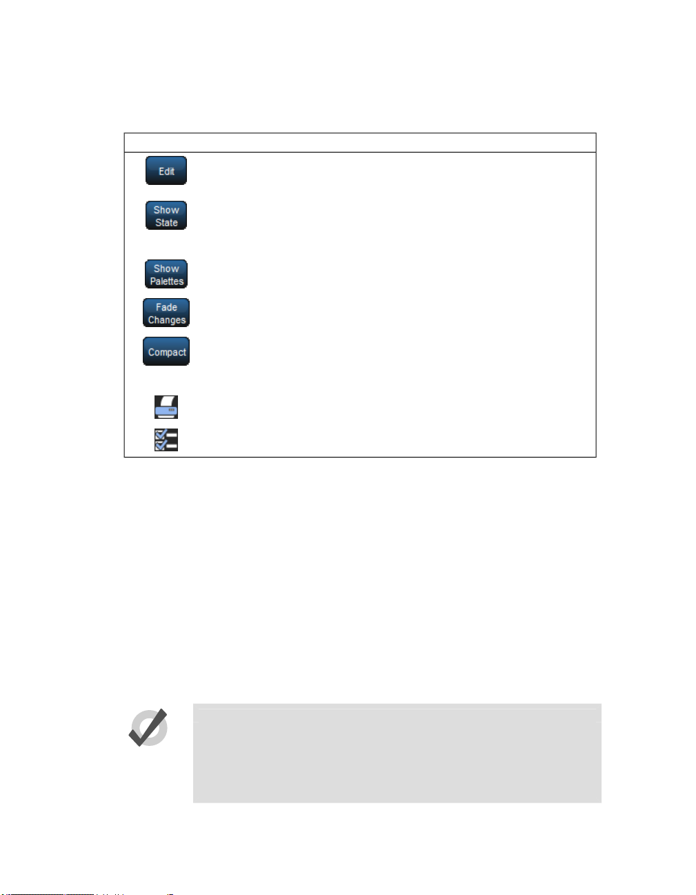
The Editor Toolbar
The Editor Toolbar has the following buttons:
Section 2: Hog 4OS Fundamentals
PurposeButton
Press this to make the contents of the editor editable, rather than just
to view it. Instructions given to the command line, or using the parameter wheels and I-Wheel, are directed to the editable editor.
In cue editors, press this to see all the parameters that will appear on
stage, including those that have tracked through from earlier cues in
the cuelist. With Show State deselected, only the hard values actually
recorded in the cue are displayed.
Press Show Palettes to see the palette name, rather than the parameter
value; see Palettes (p.151).
Press this to have parameter values changed in this editor fade rather
than snap onto stage; see Fade Changes (p.236).
Press this to toggle compact mode on and off. Compact mode fits more
information into the editor without having to scroll. However, the
column for a particular parameter won't necessarily be aligned across
different fixture types, so sorting is not possible.
Reports. This allows you to print the contents of the window.
Configure. This allows you to control various aspects of how the editor
window displays information.
The Jump Toolbar
The Jump Toolbar has a button for each type of fixture currently in the editor, allowing you to
quickly jump to the parameter values for that type of fixture. The Jump Toolbar only appears if
aggregation is turned on; see Aggregation (p.41).
2.9.2 Changing Parameter Values in the Editor
To make changes to the contents of an editor, you need to have its Edit button selected. You can
have up to eight editors open, but only one can be editable at a time, and the parameter wheels,
I-Wheel and command line all operate on the contents of the currently editable editor. If you
have several editors open at once, you can use the Edit button to determine which one you are
controlling (even if it is not the frontmost window) or to ‘lock’ the editor to prevent accidental
changes.
Tip
When you open an editor, all the fixtures within the editor are automatically selected. This aids quick editing of cues or palettes. You can also
deselect the Select All on active editor option under the Misc tab of the
preference window so that editors can be opened and closed without
changing fixture selection.
High End Systems46

Section 2: Hog 4OS Fundamentals
After you have finished editing a cue, scene or palette, press the Update key to apply changes.
Until you do this, changes won't show up if you run the cue or scene, or use the palette. The exception to this is when you are working in the Programmer, when the Update keywill perform
the Auto Update function; see Auto Update (p.235).
If you hold down the Update key, the Update Toolbar will appear. This allows you to select
which parameter types are recorded, whether changes should track forwards, and whether references should be allowed when recording palettes. See Stopping Values from Tracking Forward
(p.174) and Reference Palettes (p.159).
If you close the editor without updating, you will be asked whether you want to save or discard
the changes, or cancel the closing of the editor.
Tip
The name of the current editable editor is shown in the Command Line
Toolbar. By default, it is the Programmer. The name of the item being
edited appears in the title bar of the editor window.
2.10 Modifier Keys
The Hog 4 family of consoles all share a common set of useful multi-purpose modifier keys that
when held down extend the base functionality of other keys and wheels on the front panel similar
way to a Shift or Control key works on personal computers. There are several modifier keys but
the core modifier keys in the Hog 4OS are Pig, Open, Delete, Backspace, Set, Cue and Move.
Pig Key Modifier Examples:
1. Pig + I-Wheel : Changes wheel to proportional intensity mode.
2. Pig + Record : Pastes information into the selected location.
Pig Key Commands (p.397) has a full list of commands that use the Pig key.
2.11 Undo and Redo
The Undo button found on the Main Toolbar is similar to the undo command found in computer
applications, allowing the user to work back through the last commands entered by the user,
undoing them each time the button is pressed. In the Hog 4OS the undo key is global, working
47High End Systems

Section 2: Hog 4OS Fundamentals
back through operations in chronological order, and you can go back all the way to the point at
which you logged on to the console (generally, this is when you started the console up). In cases
where multiple consoles are networked together the undo task will only undo actions of the local
desk.
Pressing the Pig button, together with the Undo button, will redo the last undone action. Again,
if you have gone back through several undos, you can redo repeatedly until you get back to the
most recent action.
The undo and redo feature works on your show data, but generally not on other things.
Undo is not available for:
• Changes to the fixture selection in the Programmer. However, the selection
may change as a side effect of an undo action.
• Changes to Control Panel settings, and other things not directly related to your
programmed show.
• Changes to window positions and views, and the like.
If undo is not available, you will always be asked to confirm important changes before they take
place.
2.12 The File Browser
You can browse and organize several different kinds of system files in the File Browser pane of
the Show Manager window; see Figure 4.2, “The Show Manager Window”. On the left is a list
of the main console folders and the console's drives. Clicking on one of these will display its
contents in the right hand list.
The browser shows the name, description, and creation date and time of the file, as well as the
version number of the library used to create the show in parentheses. If the show is marked as
modified, then the library has been altered through a library merge.
2.12.1 Moving, Copying, Deleting and Renaming Files
To move a file:
• Drag and drop files to destinations in the left hand folder list. Generally, you
will find dragging with the mouse or Trackball much easier than using the
touchscreen.
To copy a file:
• Drag and drop files while holding down the Pig key (or the Control key on an
external keyboard).
To delete a file:
High End Systems48

Section 2: Hog 4OS Fundamentals
• Right-click on the file and select Delete from the contextual menu. You will
be asked to confirm the action.
To rename a file:
• Right-click on the file and select Rename from the contextual menu. Type in
the new name and press Enter.
Tip
You can also copy and paste files by right-clicking on them and selecting
Copy or Paste from the contextual menu.
2.12.2 Creating New Folders
You can create sub-folders in the Shows and Libraries folders to help organise your work:
1. Click on the folder you want to make a new folder in.
2.
Click on the button.
3. Enter a name for the folder and press Enter.
Note that you cannot create folders on a CD-ROM.
Tip
You can also create a new folder inside an existing one by right clicking
on it and using the contextual menu.
2.12.3 Ejecting Disks
You cannot eject a disk in the console' CD drive if it is in use. Before ejecting, make sure that
you don't have the disks folder selected in the File Browser. If a disk will not eject, check that
you are not browsing its contents elsewhere, and that the console is not currently accessing it.
2.12.4 Burning files to CD
To burn files onto a recordable CD:
1. Setup → Shows → CD Burning : see Figure 2.17, “The CD Burning pane
of the Show Manager window”.
2. Select a file to be copied in the left-hand list, and click the Add to CD button
to move it to the right-hand list. You may be asked to archive the file before
adding it to the list; click OK to agree to this.
3. Repeat for all the files you want to copy to the CD.
4. Insert a recordable CD into the CD drive, located under the console's front
wrist rest.
49High End Systems

Section 2: Hog 4OS Fundamentals
5. Press the Burn button,and then the Start Burn button in the CD Burning
window. The window will show the progress of the writing operation.
Figure 2.17. The CD Burning pane of the Show Manager window
Tip
You can use drag and drop to move files to the CD Master list. Note that
files will always be copied, not moved.
High End Systems50

Section 3: Setting Up the System
3.1 Setting Up the Console
3.1.1 Starting Up the Console
To power on and start up the console plug one end of a standard IEC power cable into any 100220 VAC power source and plug the other end into the console's dedicated IEC power port and
then turn the power switch on the back of the console to the on position. Make sure that any external bootable media such as bootable USB flash drives or CDs are removed from the console
before booting as the console may try to boot to that media instead of to the installed operating
system. When the console has finishing booting you will see two windows: the Hog 4OS splash
screen and the Hog 4OS start screen. Your console is now ready for operation.
Important
Using an ungrounded power source leads to a greater risk of shock and
may cause the motorized faders on the Hog 4 and Full Boar 4 consoles
to not function properly. Always make sure that the power source for
your console is properly grounded.
51High End Systems

Section 3: Setting Up the System
Figure 3.1. Start Screen, your console is ready to use
3.1.2 Adjusting the Date and Time
The console has a built in clock which is shown at the far right end of the command line toolbar.
To change the console's date, time, and time zone open the Control Panel and navigate to the
Time and Date tab. To change the format in which the console displays the date and time in
your show file open the Preferences window and navigate to theAppearance tab. The format
preference is stored in the show file and will change based on which show file you load.
Note: In order to permanately store changes made to the time and date of the console you must
restart the Hog 4OS or properly shutdown/reboot the console. Simply switching the console's
power switch off/on will result in any time and date changes being lost.
3.1.3 Calibrating the Touch Screens
The touch screens may occasionally need to be calibrated. Torecalibrate the touchscreens before
launching a show, select Touchscreens in the Start window. Touch each target as it appears
sequentially; see Figure3.2, “The Calibration Screen”. After the calibration sequence is complete,
press Enter. You can press the Set key to start the process again if necessary.
High End Systems52

Section 3: Setting Up the System
You can also calibrate the touch screens at any time while loaded in a show by pressing the
Calibrate Touch Screens button in the Displays pane of the Control Panel.
Figure 3.2. The Calibration Screen
3.1.4 Adjusting the Screen Brightness
You can adjust the brightness of the touch screens by holding down the Setup keyand adjusting
the parameter wheels labelled Left Backlight orRight Backlight.
Tip
If you find the graphics on the screens are too bright, you can change
the console's colour scheme to a darker one in Setup → Preferences →
Appearance.
3.1.5 Changing the LCD Backlight Timeout
The backlights that illuminate the console's primary touch screens switch off automatically after
a period of time if the console is idle. You can adjust the amount of time the backlights will wait
before switching off in the Appearance pane of the User Preferences window:
1. Setup → Preferences → Appearance
2. Adjust the Backlight Off time located at the bottom of the pane, either by
pressing the arrows to increment or decrement the value, or by clicking on the
value, pressing Set and typing in a new value.
3. Select OK to apply and close.
Tip
Once the Hog displays are asleep you can wake them up by pressing any
key. It is a good idea to use the Pig key as this will prevent you from accidentally changing any data within the show.
3.1.6 Adding External Monitors
You can attach three external displays to the Hog 4 using standard DVI or VGA connectors.
53High End Systems

To use external displays, you must enable them and set the screen resolution in the Displays
pane of the Control Panel:
• Setup → Control Panel → Displays
You will need to restart the console to enable the external monitors.
NOTE: The Full Boar 4’s DVI-D monitor output connections do not support analog output to
VGA displays such as those featured on the older Full Boar 3 playback and programming wings.
3.1.7 Adding External Touch Screens
External USB touch screens are supported on all consoles in the Hog 4 OS family. When an external touchscreen is required High End Systems recommends using Master Wing 4 or Playback
Wing 4 for the greatest level of compatability and integration. Hog 4 OS consoles are also
compatible with most "HID compliant" touchscreen monitors (check manufacturer specifciations)
and with all AccuTouch and InetlliTouch touchscreens from Elo.
To connect an external touchscreen to your console connect your touschscreen montor's DVI or
VGA video signal cable to one of the video output connections on the back of the console.
Navigate to the displays tab of the control panel and use the appropriate drop down menu to set
the resolution of the external monitor and hit apply. You will then be prompted to restart the
console. After the console has restarted plug in the touschscreen monitor's USB cable to any one
of the USB ports on the console. Once plugged in the touchscreen will automatically be detected
and begin working but may need to be calibrated; see Calibrating the Touch Screens (p.52).
Section 3: Setting Up the System
3.1.8 Keyboard
Using an External Keyboard
You can connect an external keyboard to the console via the console's USB ports. Choose a
keyboard model, and assign the keyboard layout according to the language of the keyboard you
have connected, in the Keyboard pane of the Control Panel.
Youcan adjust the timings for Repeat Delay,Repeat Period, and Double Press in the Key Timings
pane of the User Preferences window.
Tip
You can use an external keyboard to control many of the console's functions, as well as entering numbers and text; see Keyboard Shortcuts
(p.395).
Using the On-screen Keyboard
You can use the on-screen keyboard to enter text when an external keyboard is not present; see
Figure 3.3, “The On-screen Keyboard”. When prompted to insert text, press the Set key to
launch a touch-screen keyboard. You can use the Pig key as a 'shift' for uppercase characters.
Press the Enter key when you have finished typing.
High End Systems54

Section 3: Setting Up the System
To close the on-screen keyboard without making any changes, press Set instead of Enter.
Figure 3.3. The On-screen Keyboard
3.1.9 Trackball
Using an External Trackball
External USB trackballs can be connected to the console via the console's USB ports. Most external USB trackballs are supported only as an external mouse with left and right click capabilities
however a select set of trackballs (listed below) are fully supported as functional Hog 4 OS
trackballs (support for all four trackball buttons and support for the use of the trackball in both
pointer and POS mode):
Kensington Expert Mouse (Model K64325)
Kensington Orbit Wireless Mobile Trackball (Model K72352US) - (note: does not have top left
and top right buttons)
Kensington SlimBlade Trackball (Model K72327US)
3.1.10 Shutting Down and Restarting the Console
To properly shut down or restart the desk, select Setup → Quit. The Quit button is on the right
hand end of the Setup ToolbarAfter press the quit button the Shut Down dialog will open (see
Figure 3.4, “The Shut Down Dialog”), with the following options:
Figure 3.4. The Shut Down Dialog
• Shut Down: shutting down will turn the Hog console off completely.
55High End Systems

• Restart Console: restarting is like shutting the console down and turning it on
again, and will take you to the Start window.
• Log Off: logging off will close your current desktop, Programmer and output
screens, as well as closing the current show file. The console remains powered
up and running, and returns to the Start window.
• Cancel: cancels the quit command.
In all cases your show data is automatically saved to disk.
3.1.11 Locking the Console for Access
Consoles can be locked for access at any time by hitting the setup key on the console front panel
and then pressing the lock button on the quit toolbar. Consoles can also be locked remotely by
enabling the "lock local access" button under the security tab of the console settings window for
the console on the network you wish to lock.
Section 3: Setting Up the System
Figure 3.5. The Lock Button on the quit toolbar
When the console is locked the user cannot access any part of the show file or change any dmx
output to the stage. To unlock the console enter the PIN code you have setup for your console
using the touch screen, the numeric keypad on the front panel, or an external keyboard.
High End Systems56

Section 3: Setting Up the System
Figure 3.6. The Lock Window Requesting Pin
By default the lock code for consoles is 1234. To change the lock PIN code for the console open
the network window, right click on the console you want to change the settings for, click on
settings, and navigate to the security tab. Change the PIN code to the desired value and hit apply.
57High End Systems

Section 3: Setting Up the System
Figure 3.7. Security Settings Tab of Console Settings Window
If you forget the passcode and are locked out of the console you will need to powercycle the
console and relaunch the show in order to regain access to the show. Lock pin codes are stored
per show and per console.
3.2 DMX Processor 8000 Setup
To begin setting up your DMX Processor 8000 plug in mains power at any voltage between 100
and 240V AC. The DMX Processor 8000's most fundamental settings are available using the
built in front panel menu system.
To navigate through the front panel menu system of the DMX Processor 8000:
Move the cursor through the options backwards.
Select the option currently highlighted by the cursor.
Move the cursor through the options forwards.
3.2.1 Setting the Net Number
The net number is displayed on the main screen of the DMX Processor in the top right-hand
corner. To assign the net number:
1. Main → Network : navigate to the Network Configuration screen.
2. Assign the net number to any value between 01 and 99.
High End Systems58

Section 3: Setting Up the System
3. OK : return to the Main screen.
3.2.2 Setting the Port Number
To assign the Port Number:
1. Main → Network : navigate to the Network Configuration screen.
2. Assign the Port Number as required.
3. OK : return to the Main screen.
3.2.3 Setting IP Addresses for the HogNet Adapter on a DMX Processor 8000
By default, DMX Processor 8000s are set to use DHCP to get an IP addressautomatically from
a Hog console. You can turn this off in the IP Config screen:
1. Main → Network → Console → Console Link Config : navigate to the IP
Config screen.
2. Set DHCP On or Off.
3. OK : return to the Console Link Status screen.
4. Close : return to the Network Configuration screen.
5. OK : return to the Main screen.
You may want to assign a fixed or ‘static’ IP address, perhaps if the Hog system is sharing a
network with non-lighting devices such as personal computers. You should contact your system
administrator to determine the optimum settings for your network.
To assign a static IP address:
1. Main → Network → Console → Console Link Config : navigate to the IP
Config screen.
2. Set DHCP Off.
3. Set the IP Address and Subnet Mask as required.
4. OK : return to the Console Link Status screen.
5. Close : return to the Network Configuration screen.
6. OK : return to the Main screen.
3.2.4 Setting the DMX Processor back to Defaults
In the Control Panel screen you can set the DP back to it's factory default settings:
• Main → Control PanelSet to Defaults.
59High End Systems

Section 3: Setting Up the System
3.2.5 Locking the DMX Processor Front Panel Controls
You can use the Lock function to lock the DMX Processor's controls. The default PIN is 1234;
a new PIN can be assigned from a Hog console via Setup → Network on the Setup Toolbar.
Select the required DMX Processor in the network windowand click Settings. Change PIN and
OK to apply and close the window.
To lock the DMX Processor locally:
• In the Control Panel,select Lock :the Enter PIN to Unlock screen will appear.
To unlock the DMX Processor locally:
• Enter your chosen 4-digit code number,and cursor right to confirm. The code
number will be the default 1234 if you have not changed it to your own.
You can lock and unlock remotely from a console via the DMX Processor Settings window for
each specific DMX Processor:
1. Setup → Network :the Network button can be found on the Setup Toolbar.
2. Select the required DMX Processor in the Network window and click Settings
to open the DMX Processor Settings window.
3. Lock or unlock the DMX Processor and OK to apply and close the window.
Important
Make sure that you keep a record of your lock code close to hand if your
DMX Processor is located away from the console. The DMX Processor
cannot be unlocked without it or a console operator.
3.2.6 Backlight Off Time
Selecting Backlight in the Control Panel opens a screen where you can assign the delay time
before the backlight goes off. The Permanent setting keeps the light on continually.
3.2.7 Watchdog
The Watchdog feature automatically restarts the DMX Processor if its software stops running
for some reason. Watchdog is on by default, and generally it is best to leave it switched on.
However, if you suspect that an DMX Processor is not working correctly, you may want to turn
Watchdog off so that you can see any error messages before restarting it:
1. In the Control Panel, select Watchdog.
2. Deselect the Watchdog checkbox, and select OK.
High End Systems60

Section 3: Setting Up the System
3.2.8 Resetting the DMX Processor
There are two types of reset: soft and hard. Soft Reset resets the DMX Processor so that it reinitialises communication with the network. Hard Reset is equivalent to turning off and on the
DMX Processor's mains power.Youcan do both types of reset from the Control Panel. In addition, you can reset a DMX Processor by right clicking on its entry in the Network window of
the console (Setup → Network) and selecting Reset Node.
3.2.9 Checking a DMX Processor's Status
The indicator lights on the front of a DMX Processor 8000 display its status on the network.
ConnectingConnected to a showStatus
USB
HogNet
FixtureNet
(Art-Net)
Art-Net outputNet Data
USB Device connected
and active
connection
connection
Writing flash memoryWrite
not connected
configured
Slow: updating firmware
OffBlinkingOnLight
Not Connected to a
show
No DMX sending2Hz Keep AliveDMX Data outputDMX Data
Art-Net not configuredArt-Net configured, but
No USB Device foundUSB Device found but not
HogNet not connectedHogNet activityLink light for HogNet
Fixture not connectedFixture activityLink light for fixture
Normal activityFast: bootloader active
3.2.10 Expanding the DMX Outputs of a DP8000
The DMX Processor 8000 is always processing 16 universes of DMX. These universes are
available via the eight 5-pin XLR outputs on the front of the unit as well as via Art-Net. You
can expand the XLR outputs to access the full sixteen universes by using external USB Widgets.
Expanding a DMX Processor 8000 Using an Expander
When you connect a USB Expander to a USB port of a DMX Processor 8000 you will need to
configure it to outputs 9-16 of the DMX Processor.
To manually configure Widgets:
1. Setup → Network : open the Network window.
2. Select the DMX Processor 8000 in the list by clicking on its net number, and
press the Settings button to open the DMX Processor Settings window; see
Figure 3.8, “Widget Outputs pane of the DMX Processor Settings window”.
3. Select the Widget Outputs pane.
61High End Systems

Section 3: Setting Up the System
4. To configure an expander to output ports 9-16 of a DMX Processor 8000,
click on a box associated with a port (9-16) and select the expander from the
list of serial numbers that appears. Repeat for all the universes you want to
output via the widget.
5. Click OK to confirm the settings. The Expander should now have its DMX
Data indicator illuminated.
Expanding a DMX Processor 8000 Using Widgets and Super Widgets
When you connect a USB DMX Widget or Super Widget to a USB port of a DMX Processor
8000 you will need to configure it to the next available output of the DMX Processor.
To manually configure Widgets:
1. Setup → Network : open the Network window.
2. Select the DMX Processor 8000 in the list by clicking on its net number, and
press the Settings button to open the DMX Processor Settings window; see
Figure 3.8, “Widget Outputs pane of the DMX Processor Settings window”.
3. Select the Widget Outputs pane.
4. To configure an expander to output ports 9-16 of a DMX Processor 8000,
click on a box associated with a port (9-16) and select the widget from the list
of serial numbers that appears. Super Widget ports will appear with the serial
number followed by an output number. Repeat for all the universes you want
to output via the Widget.
5. Click OK to confirm the settings. The Expander should now have its Active,
DMX OK and TX Mode indicators illuminated.
A single Widget or single output of a Super Widget may only be connected to one port at any
one time. If a Widget that is already connected to one port is connected to a second port, it will
automatically be disconnected from the first port.
3.3 HogNet Network
On the back of every Hog 4OS console is a dedicated Base-T Ethernet jack that can be used for
connecting to a network of DMX Processors, computers, and other consoles. If there is more
than one Ethernet jack on the back of the console, then the jack labeled HogNet should be used.
The hardware on personal computers running Hog 4PC will vary but at least one 100 Base-T
Ethernet hardware device must be properly installed and enabled in order for Hog 4PC to successfully communicate to other nodes on a network.
All components of a Hog network should be connected using category 5 Ethernet cables and
using at least a 100mb Ethernet switch or router. Gigabit switches are also HogNet compatible.
The simplest HogNet network consists of a console and a DMX Processor connected to the
lighting rig. Only slightly more complex is the case of a system with a single console and several
High End Systems62

Section 3: Setting Up the System
Figure 3.8. Widget Outputs pane of the DMX Processor Settings window
DMX Processors connected together with an Ethernet switch. Large systems can have several
consoles, Hog 4PC systems, and DMX Processors, controlling large lighting rigs.
3.3.1 Configuring Console Network Adapters
At the top of the HogNet tab in the Control Panel, is a drop down menu of all the installed network
adapters usable by the Hog OS. The Hog 4 console will only list one network adapter and it will
be greyed out while Windows computers running Hog 4PC might have more than one network
adapter listed depending on howmany network adapters are installed and enabled on the computer.
63High End Systems

Section 3: Setting Up the System
Figure 3.9. The Network pane of the Control Panel
After selecting an adapter from the drop down menu, the area below the menu will show the
adapter’s current status:
• A link status of Up indicatesthe adapter is connected to a network and is ready
to be configured to communicate to other network devices.
• A link status of Disconnected indicates the adapter is running but is unable
to communicate to other nodes because the network cable is not connected to
a network.
• A link status of Down indicates the adapter is either disabled or in an unstable
state and is not usable for show operation.
Important
Only network adapters with a link state of UP will be able to communicate
with other nodes on the network. If none of the listed adapters are in the
UP state then the Hog 4OS will not operate on a network and will instead
operate as a standalone console using a loopback address.
Configuring an IP Address for the HogNet Network Adapter
In order for a network adapter to properly communicate on a network it must be configured with
an IP address setting that is compatible with other devices on the network. There are three main
options when configuring an IP address for a HogNet adapter:
Default IP address: select this option to use an IP address of 172.31.0.1.
Obtain an IP address using DHCP: select this option when running the console on a network
that contains a DHCP server such as a DHCP router or a Hog console running a DHCP server.
High End Systems64

Section 3: Setting Up the System
Important
If you choose to obtain an IP address using DHCP on the console and no
DHCP server is present on the network, then the console will revert to a
loopback address of 127.0.0.1 which is not a usable network address for
network show operation. In this case you should use a custom IP address.
Custom IP address: This option allows you to specify the IP address and subnet mask settings
of the Console. This option is most commonly used on networks where a DHCP server is not
present but multiple unique IP addresses need to be specified.
Enabling the DHCP Server
In addition to being DHCP client compatible, all network enabled consoles are also capable of
running a DHCP server themselves. Enabling DHCP allows the console to hand out IP addresses
to other consoles, DMX Processors, and computers on the network without needing to manually
configure static IP addresses for every device on the network.
Choosing BOOT Server ONLY
Included in the DHCP server options of the console is the Boot server. The Boot server process
is separate from the DHCP server and is used by Hog consoles to provide remote software imaging
for the DMX Processor 8000. You can select options to either run only a Boot server (with or
without a custom address range) or to run both a Boot server and a DHCP server. When running
both, the custom address range applies to both the DHCP server and the Boot server.
Using a Custom DHCP Server Range
Sometimes in more complex networks where more than one DHCP server is present, specifying
a custom DHCP server range is necessary to avoid IP address conflicts. Using a custom DHCP
address range applies to both the DHCP server and the Boot server processes. To use a custom
DHCP range on your console enable the Use custom address range button and specify the
start and end addresses in the fields below the button.
Firewalls and Hog 4PC
Firewalls help to provide increased network security by controlling access to private networks
and computers based on the public IP address of the client. Since the Hog 4OS depends on multicast network traffic for communication to other system devices it is encouraged that users configure their network and computer firewalls and security settings to allow for HogNet network
traffic. For some firewall applications this might mean turning off the firewall completely.
Configuring HogNet Network Settings on a DMX Processor
In the front panel menu system of the DMX Processor 8000 is a network configuration menu
used to configure IP address settings for that particular node. This menu can be accessed by first
selecting Network, HogNet, HogNet Config.
65High End Systems

Configuring the IP addresses and subnet addresses on Hog processors follow the exact same
rules and principals as outlined for network adapters consoles in Configuring Console Network
Adapters (p.63)
Typical HogNet Network Configurations
Example A: A single console and single DMX Processor.
Section 3: Setting Up the System
Example B: The console is a DHCP server, and all other nodes obtain an IP address from it.
Example C: A DHCP Router serves all components.
High End Systems66

Section 3: Setting Up the System
Example D: All components have a custom unique static IP address.
3.3.2 Port Number
Since multiple shows can be run on a single network, each show server running on the network
must have its own port number to keep lighting data for each show on the network seperated.
Nodes connecting to the show server must then have the same port number as the show server
console. For example, a console running a show server on the network on port 6600 means other
nodes such as DMX Processors on the network will need a port number of 6600 as well to join
that same show.
67High End Systems

3.3.3 Node Types and Net Numbers
There are two elements that help to identify a node’s role in a network show: node type and net
number. The node type is inherent to device hardware and cannot be changed. For example, a
Hog 4 is a “console” node type while a DMX Processor 8000 is a DMX Processor node type.
Secondly, there is the device’s net number. The net number is a user-configurable setting that
further defines the node’s role in a network show.For example, a DMX Processor 8000 set to
net number 1 means the DMX Processor 8000 will load and output patch information stored in
the show file for DMX Processor 8000 #1.
Important
Within a single node type each device must be set to a unique net number. For example you cannot set two physical DMX Processor 8000s to
net number 1 in a show. Only one of the DPs will actually load show data
while the other DP will sit idle as a duplicate. Consoles are the only exception to the duplicate net number rule. Individual consoles can be set
to identical net numbers which allows them to fully track one another in
terms of their current page, chosen master, and playback state. This
“tracking” feature, when combined with the failover functionality discussed in Configuring the Network for Console Failover (p.70) provides
the user with the ability to configure a tracking backup console on the
network.
3.3.4 Connecting Multiple Consoles
Section 3: Setting Up the System
Multiple Hog consoles can be connected together in various configurations when running on the
same port number. Client/Server configuration allows multiple users to program on the same
show file. Console Failover provides network backup of two or more consoles running the same
show. Console Tracking creates redundancy of all console functions across multiple consoles.
You should link all consoles and network devices to an Ethernet switch using certified Category
5 non-crossover cables.
High End Systems68

Section 3: Setting Up the System
3.3.5 Configuring the Network for Client/Server
Running the Console as a Show Server
When the Run Server option in the Settings window of the start screen is checked, the console
is enabled as a show server. A show server console is able to do three main things that it would
not otherwise be able to do as a client:
1. Start New Shows
2. Launch existing shows from disk
3. Connect to and sync a local copy of show data from other show server consoles
on the network.
Since consoles that are enabled as show servers continuously sync and store local copies of show
data during programming, setting up more than one show server in your network allows for
continued show operation should one console fail. This is method of redundancy is called “failover”. See Configuring the Network for Console Failover (p.70)
69High End Systems

Section 3: Setting Up the System
Running the Console as a Client
When the Run Server option in the Settings window of the Start screen is not checked, the
console will operate only as a client to other show server consoles on the network. As a client,
the console will not keep a local copy of the network show file and as a result will be forced to
log off the connected show session if all show servers running on the network are logged off.
Tip
The generic word server is often mentioned when working with a Hog
4OS system. There are three types of servers that are at work in a networked Hog show. The DHCP server manages IP address assignments to
other consoles, nodes, and computers on the network through the use
of Dynamic Host Control Protocol (DHCP). A Show server refers to the
server process running on the console, which manages show data and
distribution. The DHCP server and the Show server are independent of
one another and do not need to be running on the same console. The
Boot server process is used by Hog consoles to provide remote software
imaging for the DMX Processor 8000.
3.3.6 Configuring the Network for Console Failover
When two or more show server consoles are connected to a network show, a feature known as
failover is automatically enabled, allowing for one of the consoles to “fail” without causing a
loss of control over the show data or dmx output. Each show server on the network has the
ability to take over control of the show should one of the other show server consoles suffer from
power loss, a severed network connection, or localized failure. Users are encouraged to run at
least two networked show server consoles in live performance situations in the event that, if one
console fails, the show can remain running on the secondary console while the first console is
recovered.
High End Systems70

Section 3: Setting Up the System
To enable console failover:
1. Connect two consoles via an Ethernet switch.
2. Enable the Run Server option in the Settings window on each console.
3. Configure the primary console as Net number 1 and the secondary console as
Net number 2.
4. Log on primary console and then connect secondary console.
After configuring the network for failover,each console connected to the show will monitor the
status of the primary console (the console that first loaded the show on the network) for any
failures or forced log offs.
In the event that the primary console suffers a critical error or is disconnected from the network,
all other consoles connected to the show will post the message shown below, notifying the user
that a failover has occurred and indicated which of the other server consoles has taken over as
the active show server (primary console).
71High End Systems

Section 3: Setting Up the System
If you see this message, first check to see if the original primary console is still physically connected to the network, then power cycle the original primary console and reconnect it to the
show.
In the event that the console operator intentionally logged off the primary console, all other
consoles connected to the show will post the failover message shown below to indicate that the
primary server console has logged off and another server console has assumed the role as the
active show server (primary console).
Since this message is the direct result of the primary console being willfully logged off from the
show there is no need to perform any troubleshooting. Simply reconnect the logged off console
to the show and it will once again participate as a show server console on the network.
3.3.7 Configuring the Network for Console Tracking
Console tracking allows two or more consoles to track each other in terms of the chosen page,
the chosen master, and playback state while still maintaining individual desktop/programmer
experiences between the desks. A backup secondary networked show server console set to the
same net number as the primary console is recommmended when setting up Hog control systems
for live shows. This creates system redundancy and protects from total loss of control should the
primary console fail.
High End Systems72
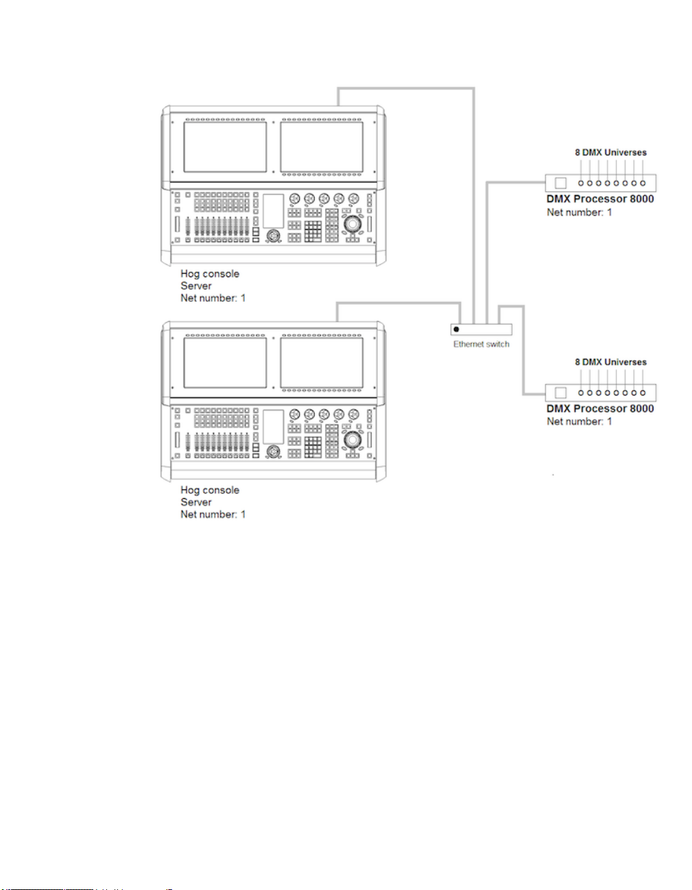
Section 3: Setting Up the System
To enable Console Tracking:
1. Connect two consoles via an Ethernet switch.
2. Enable the Run Server option in the Settings window on at least one of the
consoles. You can choose to enable the Run Server option on both consoles
to also engage failover functionality.
3. Set both consoles to Net number 1.
4. Log the primary console to a show and then connect the secondary console to
the same show.
The two consoles will nowmirror each other in terms of chosen master,current page, and playback
state.
3.3.8 More than One Show on the Network
If you want to run more than one show on the same network, you need to choose a port number
for each show. The default port number is 6600, so the second show could be on 6601, the third
73High End Systems

on 6602, and so on. You need to assign the port number of each console system and network
device according to the show it is used with.
3.3.9 Connecting to an Existing Network
You can connect the console to an existing ethernet network if desired. Contact the administrator
of the network to obtain the correct network settings.
Important
You should disable the DHCP server of the console before connecting to
an existing computer network, otherwise it may interfere with the correct
operation of the network.
3.3.10 Network File Sharing
You can connect to drives on a local network or remote computer to transfer show files. Only
compressed showfile backup (.tar.gzor .shw) files can be transferred with Network File Sharing.
Mapping Network Drives
Network drives are available within the Start window and the Backup window.
Section 3: Setting Up the System
To map a network drive:
1. Connect a remote computer or network to the HogNet network.
2. Click the Browse button in the Start or Backup window.
3.
Click on the Map Network Drive button.
4. Enter data for the following fields in the Connect to Network Disk window:
• Server name: the host name or IP address of the remote
computer
• Share name: the name of the shared directory on the remote
computer
• Username: the user name to access the shared directory on
the remote computer (if required)
• Password: the password to access the shared directory on
the remote computer (if required)
• Domain: if the user account is a member of a windows do-
main, enter that domain name here, otherwise leavethis field
blank.
High End Systems74

Section 3: Setting Up the System
Note that depending upon your network drive configuration, not all fields may
be required.
5. Check the box if you want the connection to be saved with the console. If this
option is not selected, then this mapping will be lost when the console is rebooted or power cycled.
6. Check the box to save the password if you wish to have the password for the
drive mapping saved with the above option.
Accessing Network Drives
Once a network drive is mapped, it will appear in the Start and Backup windows under the
console heading as a valid drive to browse to. Sub folders of the primary networked drive will
also be available.
Disconnecting Network Drives
When browsing a network drive, the Eject button is available in the top right corner of the
browse window. Pressing this button will un-map and disconnect the network drive.
75High End Systems

3.4 Art-Net and E1.31(sACN)
Art-Net and E1.31 (also known as streaming ACN) are two communication protocols supported
by the Hog 4OS that allow for DMX512 data to be sent over Ethernet. While each protocol is
unique in terms of specification and implementation, they both provide the ability to carry many
DMX universes over a single cat 5 Ethernet cable. This section of the manual will help you to
understand how to properly configure your console or Hog 4PC to output Art-Net and E1.31.
Section 3: Setting Up the System
Platform
Hog 4 Console
Hog 4PC
3.4.1 Identifying the FixtureNet Port
The FixtureNet port is the ethernet port Hog 4OS uses to send Art-Net and/or E1.31 data to fixtures, media servers, and DMX converters that are capable of receiving these protocols over
ethernet. The FixtureNet port is located on the rear panel of the Hog 4 Console as well as on the
rear panel of the DMX Processor 8000. Depending on the age of your DMX Procressor 8000
the port will either be labeled FixtureNet or Fixture Link.
When using Hog 4PC you have the option to select which of your computer's network adapters
will act as the FixtureNet port for outputting Art-Net and/or E1.31.
To assign one of your computer's network adapters to act as the Hog 4PC FixtureNet port:
1. Control Panel → FixtureNet
2. Select a network adapter from the list of available adapters at the top of the
window. If only one network adapter is available then it will be selected
automatically and the drop down box will be greyed out. If no network adapters
are available the drop down menu will be blank and greyed out.
Art-Net / sACN Output Capability
16 unique universes (adding DMX
Processors to HogNet network increases output capability)
16 unique universesDMX Processor 8000
matches output capability of
physically connected USB DMX
widgets (8 universe maximum)
Important
Hog 4PC will only output Art-Net and sACN for universes 1 thru 8 and a
USB DMX Widget must be connected and assigned to the matching universe.
Important
It is recommended that you do not combine HogNet and Art-Net or
E1.31(sACN) within the same network. This can produce network errors
and unreliable data. When using Hog 4PC you have the ability to assign
High End Systems76

Section 3: Setting Up the System
both HogNet and Art-Net/E1.31 to a single adapter but using separate
network adapters is strongly advised.
3.4.2 Configuring the FixtureNet Port
In order to successfully output Art-Net or E1.31 from your Hog 4 console, DMX Processor 8000,
or Hog 4PC, you must first properly configure the FixtureNet's IP address to settings that are
appropriate for your network.
To configure DMX Processor 8000's FixtureNet from the DP8000 front panel:
• Network → Fixture → FixtureNetConfig
To configure DP8000's FixtureNet from the console:
1. Setup → Network : open the Network window.
2. Select the DMX Processor 8000 and press Settings.
3. Select the FixtureNet pane of the DMX Processor Settings window;
To configure the Hog 4 console or Hog 4PC's assigned FixtureNet port from the console:
1. Setup → Network : open the Network window.
2. Selectthe DMX Processor 8000 assigned tonet number 1 (or whichever DMX
Processor is associated with the local internal DMX Processor 8000 in your
show) and press Settings.
3. Select the FixtureNet pane of the DMX Processor Settings window.
From these configurations menus you can configure the FixtureNet's IP address (source address)
in one of two ways:
• Obtain an IP address using DHCP: select this option when running the Art-
Net side of the console on a network that contains a DHCP server such as a
DHCP router. When using DHCP, the IP Address, Netmask, and Gateway
fields will be grayed out. The information contained with them is not relevant
to the DHCP configuration.
Important
If you select Obtain an IP address using DHCP on the
console and no DHCP server is present on the FixtureNet
network then the FixtureNet adapter will revert to a
loopback address of 127.0.0.1.
• Use Custom IP Settings: This option allows you to specify the IP address and
subnet mask settings of the FixtureNet adapter. This option is most commonly
used on networks where a DHCP server is not present. Once selected you will
need to enter the IP Address, Netmask, and Gateway for this device on the
network.
77High End Systems

3.4.3 Configuring Art-Net Output
Art-Net output is configurable using the Art-Net Outputs pane of the DMX Processor Settings
window.
1. Setup → Network : open the Network window.
2. Select the DMX Processor 8000 and press Settings.
3. Select the Art-Net Outputs pane of the DMX Processor Settings window,
see Figure 3.10, “Art-Net Outputs pane of the DMX Processor Settings win-
dow”.
• Universe: this field denotes which DMX universe to configure.
• Broadcast: check this box to enable Broadcasting. When enabled, all Art-Net
information will be sent to all nodes.
• UnicastIP: when the Broadcast field is not checked, enter an IP address of an
Art-Net node to Unicast the universe’s data to.
• Subnet: click to select the Art-Net subnet (0-15) to transmit this universe’s
data on. By default, the subnet will match the Node number of the DMX Processor 8000.
• Universe: click to select the Art-Net Universe (0-15) to transmit this universe’s
data on.
• Changes Only: check this box to transmit only changes to Art-Net data.
• –/ + : click these keys to expand or reduce the number of Art-Net configurations
for a specific DMX universe.
Section 3: Setting Up the System
3.4.4 Configuring E1.31(sACN) Output
E1.31 Output is configurable using the E1.31 pane of the DMX Processor window.
1. Setup → Network : open the Network window.
2. Select the DMX Processor 8000 and press Settings.
3. Select the E1.31 pane of the DMX Processor Settings window, see Fig-
ure 3.11, “E1.31 pane of the DMX Processor Settings window”.
• Universe: this field denotes which DMX universe to configure.
• Multicast: check this box to enable Multicasting. When enabled, all E1.31 in-
formation will be sent to all nodes.
• Destination IP: when the Multicast field is not checked, enter an IP address to
Unicast E1.31 data to.
• Universe: click to select the E1.31 Universe to transmit this universe’s data
on.
• Changes Only: check this box to transmit only changes to E1.31 data.
High End Systems78

Section 3: Setting Up the System
Figure 3.10. Art-Net Outputs pane of the DMX Processor Settings window
E1.31 supports two styles of priority. The first is a per-universe priority that defines a single
priority for all of the slots within the universe. The second style, per-slot priority, allows a separate priority be be assigned to each individual slot within that universe. Not all E1.31 receivers
support per-slot priority.On those receiversthat support per-slot priority, the per-universe priority
will be ignored when per-slot priority is enabled.
• Priority : : click to the per-universe priority for the E1.31 data being sent for
that universe of data. Valid settings range from 0 to 200, with higher numbers
representing higher priority.
• Per Slot Priority : : click on the Enable button to enable per-slot priorities for
the universe. Click on the Configure button to set the per-slot priority values
for individual slots within that universe. Valid settings range from 0 to 200.
Higher numbers represent higher priority.A slot priority of 0 indicates that the
slot should be ignored.
• –/ + : click these keys to expand or reduce the number of E1.31 configurations
for a specific DMX universe.
79High End Systems

Section 3: Setting Up the System
Figure 3.11. E1.31 pane of the DMX Processor Settings window
When E1.31 is configured and fixtures are patched, the Net Data LED on the DMX Processor
8000 will illuminate to indicate E1.31 Output.
3.5 Adding Playback Wings
You can increase the number of physical masters on your console as well as add an additional
touchscreen monitor by attaching a Hog 4 Playback Wing.
High End Systems80

Section 3: Setting Up the System
Figure 3.12. Docking Playback Bars with wings and external displays
To attach a Playback Wing:
1. Apply AC power to the wing and connect the wing's USB port and DVI port
to the console.
2. Setup → Control Panel → Wings : open the Wings pane of the Control
Panel window (see Figure 3.13, “The Wings pane of the Control Panel with
Playback Wing Mapping”).
3. Attach the wing to one of the playback bars by selecting the wing's unique ID
number in the drop down menu for that playback bar.
4. If you have more than one wing, you can identify which is which by pressing
the Beacon button for the appropriate playback bar. The LEDs on the wing
will flash.
5. Ensure that the playback bar is visible by selecting its Display button.
6. Enable the external monitor included on the wing navigate to the Dispalys tab
of the control panel and enable the cordinating DVI output where you plugged
in the wing.
NOTE: The Full Boar 4’s DVI-D monitor output connections do not support
analog output to VGA displays such as those featured on the older Full Boar
3 playback and programming wings.
81High End Systems

Section 3: Setting Up the System
Figure 3.13. The Wings pane of the Control Panel with Playback Wing Mapping
3.6 Adding Master Wings
You can increase the number of physical masters by adding Master Wings to the console. The
Master Wing is a USB device with 30 faderless masters, a rate wheel, and a 15" LED baclit
screen. The backit LED screen can be enabled to display any information you move to that
monitor including Playback Bars. The Master Wing connects to the console in the control panel
under the playback wings section. The Master wing's desklight and front panel LED settings will
always match the console. The virtual fader levelof the 30 faderless masters on the Master Wing
can be configured in the Virtual Faders pane of the User Preferences window.
To attach a Master Wing:
1. Apply AC power to the wing and connect the wing's USB port and DVI port
to the console. The rate wheel on the Master Wing will already begin to
function at this time with no further configuration.
2. Setup → Control Panel → Wings : open the Wings pane of the Control
Panel window (see Figure 3.14, “The Wings pane of the Control Panel with
Master Wing mappings”).
3. Click on the drop down menu for one of the playback bars listed in the control
panel and select one of the master wing's sections to assign it to that playback
High End Systems82

Section 3: Setting Up the System
bar. The Master Wing has three three assignable sections: Hog4Master Top,
Hog4Master Middle, and Hog4Master Bottom which cordinate to the three
rows of masters on the control surface of the Master Wing.
4. If you have more than one wing, you can identify which wing is which by
pressing the Beacon button for any assigned playback bar. The LEDs on the
wing will flash.
5. Ensure that the playback bars that you have assigned to the Master Wing are
visible by selecting the Display button for those particular playback bars.
6. To enable the external monitor included on the wing navigate to the displays
tab of the control panel and enable the cordinating DVI output where you
plugged in the wing.
Figure 3.14. The Wings pane of the Control Panel with Master Wing mappings
3.7 Adding DMX Widgets
The number of physical dmx connections on the back of the Hog 4 Console and the DP8000 is
actually lower than the number of dmx universes these devices are actually capable of outputting.
Connecting external USB dmx widgets to your Hog 4 Console, DMX Processor 8000, or Hog
4PC is the best way realize the full dmx output potential of your setup.
Widgets to fully
reach DMX output
potential
8 Single or 2 Super or
1 Super-duper
8 Single or 2 Super or
1 Super-duper
8 Single or 2 Super or
1 Super-duper
Hog 4
Console
DMX
Processor
8000
Hog 4PC
DMX
Output
Potential
verses
verses
verses
Built-in
DMX Outputs
8 Universes16 Uni-
8 Universes16 Uni-
None8 Uni-
To attach an external DMX widgets:
1. Connect the USB port of the dmx widget to the an open USB port on the
console (Superwidgets also require an external DC power source).
2. Setup → Network......
3. Assign the dmx widget to one of the available dmx outputs of the internal
DP8000 by selecting the wing's unique ID number in the drop down menu.
83High End Systems

Section 3: Setting Up the System
4. If you have more than one dmx widget plugged in, you can identify which is
which by pressing the Beacon button for the appropriate universe output
mapping.
High End Systems84

Section 4: Shows
4.1 Launch a New Show
To launch a new show press the Launch New Show button in the start window. A browser
window will open. Select the directory where you wish to store the show, give it a name, and
then press the finish button. The console will then launch all the neccessary processes to get you
up and running in your new blank show.
TIP
If the launch new show button is greyed out or unavalaible make sure
that the "run server" option is checked in the start screen's settings
window. If "run server" is checked but the new show button is still greyed
out then it's possible another console is running a show on the same port
on the network.
4.2 Launch an Existing Show
To launch an existing show press the Launch Existing Show button in the start window to
launch the last launched show file. Alternatively you can press the Browse button to select from
existing shows on your console's hard drive, a USB flash drive, or a CD. Show files with a
icon are "ready to launch" existing show files. Show files that have a icon are archived show
files and will need to be extracted to the hard drive in order to load. The unarchiving process is
done automatically by the console but will slightly lengthen the amount of time needed to launch
the show.
4.3 Connect to a Network Show
To connect to a show already running on the network look at the "connect to show" section of
the start window. If a show is running on the network and on the same port number then it's file
name will show up on the button. Pressing the button will connect the console to that show.
If "No Show found" is displayed on the button then it's possible your network settings may need
to be reconfigured in order to connect to a network show. First check the following :
• Make sure your console is set to the same port number as the server console on
the network.
85High End Systems

Section 4: Shows
• Check that your console's IP address settings are correct for that particular
network setup.
4.4 Change the Currently Loaded Show
If you are logged into a show but want to change to a different show:
1. Setup → Quit
2. Select Log Off.
3. In the Start window,either launch a new show or browse to launch an existing
show.
4.5 Automatically Launch a Show at Console Startup
You can assign the Hog 4OS to automatically launch an existing show file at startup:
1. Setup → Control Panel → Auto Launch :
2. Select Enable Auto Launch.
3. Choose a show file you wish to auto-launch.
4. Assign a delay time which will determine howlong the console will wait before
the show is automatically launched.
At startup, a pop-up window will tell you that the show will be launched automatically after the
assigned delay; see Figure 4.1, “The Auto Launch window”. Click Load Now to ignore the re-
maining delay and launch the show immediately. Click Cancel to return to the Start window. If
you specified a delay of 0 seconds, the delay window will not be displayed.
Figure 4.1. The Auto Launch window
High End Systems86

Section 4: Shows
4.6 Managing Show Data
All show data is stored on the internal hard disk of the console. Show files and folders are stored
in the Shows folder while libraries are stored in the Libraries folder.
As you edit your show file all of your changes are immediately saved to the console's internal
hard disk. In the event of power failure the Hog 4OS will have already saved the show data to
disk so that none of your work is lost.
You can use the Show Manager window (see Figure 4.2, “The Show Manager Window”) to
backup your current show file, check the integrity of your current show file's data, or to move,
copy, and delete existing shows files.
To open the Show Manager:
• Setup → Shows
Figure 4.2. The Show Manager Window
4.7 Startup Comment Macros
You can assign comment macros to be executed when a show file is launched. Comment macros
can be used to automate a variety of tasks such as recalling views or changing pages. Startup
comment macros are assigned in the Misc pane of the User Preferences window:
• Setup → Preferences → Misc
87High End Systems

Section 4: Shows
For details of the macro syntax, see Macros (p.319).
4.8 Backing Up Your Show
It is recommended that you backup your show file regularly by saving a compressed copy of
your show file on the console's hard disk or on a USB Flash Drive. Backup files are small in size
and are also easy to transfer from one console to another.Compressed backups provide a method
for reverting to older archives of your show file should a major problem occur with your show
file.
Use the following steps to make a compressed show file backup:
1. Setup → Shows → Current Show
2. Click Backup.
3. Browse to a location on the hard drive or an external disk to save the backup
file.
4. Click OK. A compressed copy of your show will be savedwith ‘_bck’ appended
to its file name.
High End Systems88

Section 4: Shows
Tip
You should backup your show files to external media regularly so that if
something catostrophic happens to you console or internal hard drive
you can still access the backups.
The Hog 4 and Full Boar 4 consoles also feature a quick backup button on the bottom right hand
side of the right screen's main toolbar. Clicking on the "backup" button will quickly generate a
backup of your show file in the shows directory using your show file's name. If other backups
with the same name exist in the shows directory the console will automatically append the new
backup file with a number.
4.9 User Preferences
Settings within the User Preferences window are stored as part of the show file and are applied
whenever the show file is launched.
4.9.1 Desklight, Worklight, and Vent Light Preferences
You can individually adjust the brightness of the console's desklights, worklight, and front panel
key LEDs by holding down the Setup key and adjusting the cordinating parameter wheel.
The vent light brightness level on the Hog 4, Full Boar 4, and Road Hog 4 consoles is controlled
by a slider that is located in in the Appearance pane of the User Preferences window. The
vent light will turn off during periods of console unactivivityas determined by the Changing the
LCD Backlight Timeout (p.53) setting. Similar to the desk lights, the vent light will come on at
full intensity on a cold boot before you have loaded a show file.
The desklights feature both blue and white LEDs. By default the desklights are white during
normal activity and turn blue during periods of unactivivity as determined by the Changing the
LCD Backlight Timeout (p.53) setting. If you prefer the desklights to always be blue, you can
select Use Blue Desklights in the Appearance pane of the User Preferences window.
4.9.2 Touchscreen Backlight Brightness
You can adjust the brightness of each of the console's touchscreen backlights by holding down
the Setup key and adjusting the cordinating parameter wheel.
4.9.3 Trackball and Trackball Ring Preferences
The Trackball and it's outer ring have two modes:
• Pointer Mode: The trackball controls the on-screen pointer, like a mouse on
a personal computer while the trackball ring acts as a vertical scroll wheel.
89High End Systems

You can switch between the two modes by pressing the top right Trackball key.
To lock the Trackball to one mode:
Trackball Keys
You can configure the function of the four keys surrounding the Trackball according to the current
mode (pointer or position). For example, in pointer mode you can have Right Click, Left Click,
Flip and Ball Mode mapped while in position mode you could have Flip, Next, Ortho Toggle
and Ball Mode mapped. The Trackball keys are assigned in the Track Ball pane of the User
Preferences window; see Figure 4.3, “The TrackBall pane of the User Preferences window”.
Section 4: Shows
• Position Mode: The trackball lights up in blue and controls the position (pan
and tilt) of fixtures while the trackball ring controls whichever function is assigned to it in the Trackball tab of the User Preferences window.
1. Setup → Preferences → Trackball
2. Select Pointer or Position from the drop down menu to lock the Trackball in
that mode. Select Toggles to restore the ability to change modes with the top
right Trackball key.
3. Select OK to apply and close.
Tip
Make sure you have an external mouse connected if you lock the Trackball
in position mode, and you don't want to control the on screen pointer
only by pressing the touchscreens.
High End Systems90

Section 4: Shows
Figure 4.3. The Track Ball pane of the User Preferences window
The following navigation functions are available:
• Ball Mode: switches the Trackball between position and pointer modes.
• Ortho Toggle: switches the Trackball between Ortho and Normal. When in
position mode, with ortho on, the Trackball will only control pan or tilt, not
both at the same time. This can be useful for accurately setting fixtures.
• Right Click: the same as a right-click with the mouse. This is usually used to
bring up a contextual menu with commands such as copy and paste.
• Left Click: the same as left-click with the mouse.
• Shuffle: shuffles the pointer across windows, bringing that window to the front
(unlike shuffle on the Window Control Toolbar which shuffles the screen
view).
• Swap to Screen: moves the pointer between screens (useful for when external
displays are connected to quickly move between screens).
• Set: the same as the Set key, but closer to the Trackball for quick cell editing.
91High End Systems

• Close Window: closes the active window.
• Toggle KindKeys/CmdKeys: toggles the function keys between kind mode
and command key mode.
In addition, the following fixture and playback functions are available:
• Next: sub-selects the next fixture in the current selection. See Sub Selections
(p.125).
• Back: sub-selects the previous fixture in the current selection. See Sub Selections
(p.125).
• Select All: selects all the fixtures currently in the Programmer. See Select All
(p.124).
• Flip: changes the pan and tilt of a moving head fixture to point at the same
position on the stage, but from the other end of its movement range. See Flip
(p.129).
• Fade Changes: toggles the state of the Fade Changes button in the activeeditor.
See Fade Changes (p.236).
• Next Page: advancesto the next page in the page directory.See Changing Page
(p.280).
• Out: assigns the current selection's intensity to zero; see Intensity (p.127).
Section 4: Shows
The default settings for the Trackball keys are:
4.9.4 Center Wheel Preferences
The user preference for which fixture functions are assigned to the center wheel on the front
panel of the Hog 4 Console is managed in the Center Wheel pane of the User Preferences
window. In this window you can assign as many functions as you like to the center wheel by
dragging functions from left hand side of the window to the wheel display on the right hand side
of the window. To delete functions from the center wheel click on the function in the right hand
pane of the preferences window to highlight the function in blue and then press the delete key
on the console front panel.
Position ModePointer ModeTrackball Key
flipfliptop left
ball modeball modetop right
nextleft clickbottom left
ortho toggleright clickbottom right
High End Systems92

Section 4: Shows
When a fixture selection is made functions assigned to the center wheel will be diplayed on the
toolbar located at the bottom of the front panel's center display. Functions that you've assigned
to the center wheel wil only be displayed if they are valid for your current fixture selection.
To cycle the center wheel through the functions press the button to the bottom right of the center
wheel. The action of the button to the bottom left of the center wheel is determined by the Encoder
Wheel Options preference (see See Encoder Wheel Button Options (p.94)). The inner part of
the center wheel acts exactly like the main encoder wheels on the desk. The outer spring loaded
ring of the center wheel acts more like a shuttle whereby a movein either direction will initialize
a value change at a fixed rate. The more you turn the ring the high the rate of change.
93High End Systems

4.9.5 Encoder Wheel Button Options
You can adjust the action that occurs when pressing the grey encoder wheel button (located to
bottom left of each encoderwheel) in the Programming paneof the User Preferenceswindow:
FunctionSetting
Fine Mode (default)
Cycle Feature Mode
When encoder wheel button is pressed and held encoder
wheel adjustments will be more refined (same as holding pig
key).
When encoder wheel button is pressed the selected mode of
the function assigned to that encoder wheel will change.
Section 4: Shows
4.9.6 Keys and Button Preferences
You can adjust various key timings in the Key Timings pane of the User Preferences window:
FunctionSetting
Key repeat delay
Key double press time
When you hold down a key, this is the delay before it starts
to repeat.
When you hold down a key, this is the time between repeats.Key repeat period
When you press a key twice within this time, the console in-
terprets this as a double-press.
Note: these timings only apply to the physical keys on the console's front panel, and not to the
on-screen buttons.
Tip
Double-pressing a key is often a shortcut way of opening the window
associated with the key; for example, double pressing the Beam key will
open the Bean directory window. If you prefer not to use the double-press
shortcuts, then assign the double-press time to zero to disable it.
High End Systems94

Section 4: Shows
4.9.7 Importing and Exporting Show Preferences
You can export the user preference settings as a separate file so that you can later import them
into any show that you are working on. To export your user preferences:
1. Setup → Preferences : open the User Preferences window.
2. Click on the Export button, and select a location to save the preferences file
to.
To load your preferences into the current show:
1. Setup → Preferences : open the User Preferences window.
2. Click on the Import button, browse to the location of your preferences files,
and select a preferences file to import.
4.10 Merging Shows
Show merging allows you to take the programming from one show and merge it into another
show. Tomerge show files you must first load the show you want to merge data into. This is
known as the current show. The show you then select to merge data in from is called the source
show.
To select a source show to merge in:
1. Setup → Shows → Current Show : opens the Current Show pane of the
Show Manager.
2. Press Merge to be guided through the merge process. The MergeShowwindow
will open; see Figure 4.4, “The Source Location page of the Merge Show
window”.
3. Choose a source show file. Note that if you have chosen a backup (.bck or
.shw) file, it may take a few extra moments for the console to uncompress the
show file and read its contents.
4. Once you have chosen a source show, you will be offered several merge options: Fixture Types, Fixtures, and Programming (groups, palettes, cuelistst,
scenes, pages, macros, and views).
95High End Systems

Section 4: Shows
Figure 4.4. The Source Location page of the Merge Show window
4.10.1 Merging Fixture Types
Once you have selected a source show, Hog 4OS compares the fixture types contained within
each show file and creates a list of fixture types which have changed; see Figure 4.5, “The Type
Merge page of the Merge Show window”.
High End Systems96
 Loading...