

Page 1

Lighting Control System
User Manual
Version 3.5.0-EN
1High End Systems
Page 2

Hog 4 Lighting Control System: User Manual
High End Systems
by Chris Muenchow and Michael Graham
Copyright
© High End Systems, Inc. 2016, All Rights Reserved.
Changes
Information and specifications in this document are subject to change without notice. High End Systems, Inc.
assumes no responsibility or liability for any errors or inaccuracies that may appear in this manual.
Trademarks
The High End Systems, Flying Pig Systems, and Hog 4 logos are registered trademarks of High End Systems,
Inc.
All other brand names and product names used in this book are trademarks, registered trademarks, or trade
names of their respective holders.
FCC Information
This equipment has been tested and found to comply with the limits for a Class A digital device, pursuant to
part 15 of the FCC rules.These limitsaredesigned to provide reasonable protection againstharmful interference
when theequipmentisoperatedina commercial environment.Thisequipmentgenerates,uses,andcan radiate
radio frequency energy and, if not installed and used in accordance with the instruction manual, may cause
harmful interference to radio communications. Operation of this equipment in a residential area is likely to
cause harmful interference,in whichcase theuserwill berequiredtocorrect theinterferenceat hisownexpense.
Product Modification Warning
High End Systems products are designed and manufactured to meet the requirements of United States and
International safety regulations. Modifications to the product could affect safety and render the product noncompliant to relevant safety standards.
Mise En Garde Contre La Modification Du Produit
Les produits HighEnd Systems sont conçus etfabriqués conformément aux exigences des règlements internationaux de sécurité. Toute modification du produit peut entraîner sa non conformité aux normes de sécurité
en vigueur.
Produktmodifikationswarnung
Design und Herstellung von High End Systems entsprechen den Anforderungen der U.S. Amerikanischen
und internationalenSicherheitsvorschriften.Abänderungendieses Produktes können dessen Sicherheitbeeinträchtigen und unter Umständen gegen die diesbezüglichen Sicherheitsnormen verstoßen.
Avvertenza Sulla Modifica Del Prodotto
I prodotti di High End Systems sono stati progettati e fabbricati per soddisfare i requisiti delle normative di
sicurezza statunitensi ed internazionali. Qualsiasi modifica al prodotto potrebbe pregiudicare la sicurezza e
rendere il prodotto non conforme agli standard di sicurezza pertinenti.
Advertencia De Modificación Del Producto
Los productosdeHigh EndSystems están diseñadosy fabricados para cumplir losrequisitosdelas reglamentaciones de seguridad de los Estados Unidos e internacionales. Las modificaciones al producto podrían afectar
la seguridad y dejar al producto fuera de conformidad con las normas de seguridad relevantes.
High End Systems2
Page 3

製品変更に対する警告
High End Systems 製品はアメリカ合衆国及び、国際安全基準の必要条件を満たすよう設計及び製造されてい
ます。この為、製品に対する変更は安全に対して影響を及ぼす場合及び、関連安全基準に満たない状態にす
る場合があります。
Important Safety Information
Instructions pertaining to continued protection against fire, electric shock, and injury to persons are found in
Safety Warnings (p.483).
Please read all instructions prior to assembling, mounting, and operating this equipment.
Important: Informations De Sécurité
Les instructions se rapportant à la protection permanente contre les incendies, l'électrocution et aux blessures
corporelles se trouvent dans Informations Importantes Sur La Sécurité (p.484).
Veuillez lire toutes les instructions avant d'assembler, de monter ou d'utiliser cet équipement.
Wichtige Sicherheitshinweise
Sicherheitsanleitungen zum Schutz gegen Feuer, elektrischen Schlag und Verletzung von Personen finden Sie
in Wichtige Hinweise Für Ihre Sicherheit (p.484).
Vor der Montage, dem Zusammenbau und der Inbetriebnahme dieses Geräts alle Anleitungen sorgfältig
durchlesen.
Informazioni Importanti Di Sicurezza
Le istruzioni sulla protezione da incendi, folgorazione e infortuni sono contenute nell Sezione 35.5, «Importanti
Informazioni Di Sicurezza».
Si prega di leggere tutte le istruzioni prima di assemblare, montare e azionare l'apparecchiatura.
Informacion Importante De Seguridad
En el Información Importante De Seguridad (p.485) se encuentran instrucciones sobre protección continua contra
incendios, descarga eléctrica y lesiones personales.
Lea, por favor, todas las instrucciones antes del ensamblaje, montaje y operación de este equipo.
重要な安全に関する情報
継続した火災、感電、及び、人の負傷からの保護に関する指示は、
い。
この装置を組み立て、設置、操作等を行う前に全ての指示を読んで下さい。
Warranty Information
Limited Warranty: Unless otherwise stated, your product is covered by a two year parts and labour limited
warranty. It is the owner's responsibility to furnish receipts or invoices for verification of purchase, date, and
dealer or distributor. If purchase date cannot be provided, date of manufacture will be used to determine
warranty period.
Returning an Item Under Warranty for Repair: It is necessary to obtain a Return Material Authorization
(RMA) number from your dealer or point of purchase BEFORE any units are returned for repair. The manufacturer will make the final determination as to whether or not the unit is covered by warranty.
Any Product unit or parts returned to High End Systemsmust be packaged in a suitable manner to ensure the
protection ofsuch Product unit or parts, and such package shall beclearlyand prominently marked to indicate
that the package contains returned Product units or parts and with an RMA number. Accompanyall returned
安全に関する情報
(p.487) を参照して下さ
3High End Systems
Page 4

Product unitsorpartswith awrittenexplanationof the alleged problem or malfunction.Shipreturned Product
units or parts to: 2105 Gracy Farms Lane, Austin, Texas 78758, USA.
Note: Freight Damage Claims are invalid for products shipped in non-factory boxes and packing materials.
Freight: All shipping will be paid by the purchaser. Under no circumstances will freight collect shipments be
accepted.
REPAIR OR REPLACEMENT AS PROVIDED FORUNDER THISWARRANTY IS THE EXCLUSIVE REMEDY
OF THE CONSUMER. HIGH END SYSTEMS, INC. MAKES NO WARRANTIES, EXPRESS OR IMPLIED,
WITH RESPECT TO ANY PRODUCT, AND HIGH END SPECIFICALLY DISCLAIMS ANY WARRANTY OF
MERCHANTABILITY OR FITNESS FOR A PARTICULAR PURPOSE. HIGH END SHALL NOT BE LIABLE
FOR ANY INDIRECT, INCIDENTAL OR CONSEQUENTIAL DAMAGE, INCLUDING LOST PROFITS,
SUSTAINED OR INCURREDINCONNECTIONWITHANYPRODUCT ORCAUSED BY PRODUCTDEFECTS
OR THE PARTIAL OR TOTAL FAILURE OF ANY PRODUCT REGARDLESS OF THE FORM OF ACTION,
WHETHER IN CONTRACT, TORT (INCLUDING NEGLIGENCE), STRICT LIABILITY OR OTHERWISE,
AND WHETHER OR NOT SUCH DAMAGE WAS FORESEEN OR UNFORESEEN.
Warranty is void if the product is misused, damaged, modified in any way, or for unauthorized repairs or
parts. This warranty givesyou specific legal rights, and you may alsohave other rights specific to your locality.
Third Party Software Acknowledgements
AMD: This product uses the Catalyst fglrx drivers.
Boost: The product include Boost software distributed under the Boost Software License, Version 1.0, ht-
tp://www.boost.org/LICENSE_1_0.txt.
Botan: This product includes software developed by the Botan Project and its contributors. Copyright © 19992005 The Botan Project. All rights reserved.
Libtar: This product includes software developed by the University of Illinois Board of Trustees and Mark D.
Roth. Copyright © 1998-2003 University of Illinois Board of Trustees. Copyright © 1998-2003 Mark D. Roth.
All rights reserved.
QT: The Qt GUI Toolkit is Copyright (C) 2011 Nokia Corporation and/or its subsidiary(-ies). Contact: Nokia
Corporation (qt-info@nokia.com).Qtis availableunderthe LGPL version 2.1 (GNU LesserGeneralPublicLicense
version 2.1).
X11(TM) and X Window System(TM): is a trademark of The XFree86 Project, Inc.
XFree86: is a trademark of The XFree86 Project, Inc.
Xorg: Xorg iscopyright software, provided under licensesthat permitmodification andredistributionin source
and binary formwithout fee. Xorg is copyright by numerous authors and contributorsfrom aroundthe world.
Licensing informationcan be foundathttp://www.x.org. Refertothe sourcecodeforspecific copyright notices.
High End Systems4
Page 5

Declaration of Conformity
According to ISO/IEC Guide 22 and EN45104
High End SystemsManufacturer's name:
High End SystemsDistributor's name:
2105 Gracy Farms Lane, Austin TX 78758, USADistributor's address:
Declares that the product:
Hog 4Product Name:
AllProduct Number:
AllProduct Options:
Conforms to the following EEC directives:
73/23/EEC, as amended by 93/68/EEC
89/336/EEC, as amended by 92/31/EEC and 93/68/EEC
Equipment referred to in this declaration of conformity was first manufactured in
compliance with the following standards in 2002:
EN60950:2000Safety:
EN55103-1:1996 (E2)EMC:
EN55103-2:1996 (E2)
I, the undersigned, hereby declare that the equipment specified above conforms to the
above Directives and Standards.
Kenneth Stuart Hansen, Compliance Engineer
30 June 2012
iHigh End Systems
Page 6

Page 7

Table of Contents
1: Getting Started ................................................................................... 19
1.1 About this Manual ...................................................................... 19
1.2 Manual Symbols ........................................................................ 19
2: Hog 4OS Fundamentals ....................................................................... 21
2.1 The Command Line ................................................................... 21
2.2 The Graphical User Interface ...................................................... 23
2.3 Abstraction ............................................................................... 30
2.4 Tracking .................................................................................... 31
2.5 HTP and LTP ............................................................................... 32
2.6 Colour Matching ....................................................................... 32
2.7 Palettes and Directories .............................................................. 35
2.8 Spreadsheets ............................................................................ 40
2.9 Editors ...................................................................................... 45
2.10 Modifier Keys ........................................................................... 47
2.11 Undo and Redo ....................................................................... 48
2.12 The File Browser ........................................................................ 49
3: Setting Up the System .......................................................................... 53
3.1 Setting Up the Console ............................................................... 53
2.1.1 Command Line Syntax ..................................................... 21
2.1.2 The Status Bar .................................................................. 22
2.2.1 Window Management .................................................... 24
2.3.1 Referring to Fixtures .......................................................... 30
2.3.2 Real World Units .............................................................. 30
2.3.3 Complex Parameters ....................................................... 30
2.3.4 Interchangeable Fixtures ................................................. 30
2.6.1 Colour Models ................................................................ 32
2.6.2 The Colour Matching System ............................................ 34
2.7.1 Automatic Naming of Directory Items ................................ 37
2.7.2 Colour Coding Directory Items .......................................... 38
2.8.1 Compact Mode ............................................................. 42
2.8.2 Aggregation ................................................................... 42
2.8.3 Cut, Copy and Paste ....................................................... 45
2.9.1 Editor Window Controls .................................................... 46
2.9.2 Changing Parameter Values in the Editor .......................... 47
2.12.1 Moving, Copying, Deleting and Renaming Files ................ 49
2.12.2 Creating New Folders ..................................................... 49
2.12.3 Ejecting Disks ................................................................. 50
2.12.4 Burning files to CD .......................................................... 50
3.1.1 Starting Up the Console .................................................... 53
3.1.2 Adjusting the Date and Time ............................................ 53
3.1.3 Calibrating the Touch Screens .......................................... 54
3.1.4 Adjusting the Touschscreen LCD Backlight ......................... 54
3.1.5 Changing the LCD Backlight Timeout ................................ 55
3.1.6 Adding External Monitors .................................................. 55
3.1.7 Adding External Touch Screens ......................................... 55
3.1.8 Keyboard ....................................................................... 57
3.1.9 Trackball ......................................................................... 58
3.1.10 Shutting Down and Restarting the Console ....................... 58
iiiHigh End Systems
Page 8

Lighting Control System
3.1.11 Locking the Console for Access ....................................... 59
3.2 DMX Processor 8000 Setup .......................................................... 61
3.2.1 Setting the Net Number ................................................... 61
3.2.2 Setting the Port Number .................................................. 61
3.2.3 Setting IP Addresses for the HogNet Adapter on a DMX
Processor 8000 ....................................................................... 61
3.2.4 Setting the DMX Processor DMX Output Refrsh Rate ............ 62
3.2.5 Setting the DMX Processor back to Defaults ....................... 62
3.2.6 Locking the DMX Processor Front Panel Controls ................. 62
3.2.7 Backlight Off Time ........................................................... 63
3.2.8 Watchdog ..................................................................... 63
3.2.9 Resetting the DMX Processor ............................................ 63
3.2.10 Checking a DMX Processor's Status .................................. 64
3.2.11 Expanding the DMX Outputs of a DP8000 ......................... 64
3.3 HogNet Network ........................................................................ 65
3.3.1 Configuring Console Network Adapters ............................. 67
3.3.2 Port Number ................................................................... 71
3.3.3 Node Types and Net Numbers .......................................... 71
3.3.4 Connecting Multiple Consoles ......................................... 72
3.3.5 Configuring the Network for Client/Server .......................... 72
3.3.6 Configuring the Network for Console Failover .................... 73
3.3.7 Configuring the Network for Console Tracking ................... 77
3.3.8 More than One Show on the Network ............................... 79
3.3.9 Connecting to an Existing Network ................................... 79
3.3.10 Network File Sharing ....................................................... 79
3.4 Art-Net and E1.31(sACN) ............................................................ 81
3.4.1 Identifying the FixtureNet Port ........................................... 81
3.4.2 Configuring the FixtureNet Port ......................................... 82
3.4.3 Configuring Art-Net Output .............................................. 83
3.4.4 Configuring E1.31(sACN) Output ...................................... 83
3.5 Adding Playback Wings ............................................................. 85
3.6 Adding Master Wings ................................................................. 87
3.7 Adding DMX Widgets ................................................................. 88
3.8 DMX Widget Status LEDs ............................................................. 90
4: Shows ................................................................................................ 91
4.1 Launch a New Show .................................................................. 91
4.2 Launch an Existing Show ............................................................ 91
4.3 Connect to a Network Show ....................................................... 91
4.4 Change the Currently Loaded Show ........................................... 92
4.5 Automatically Launch a Show at Console Startup ........................ 92
4.6 Managing Show Data ................................................................ 93
4.6.1 Recovering Show Files from a console that won't boot ........ 94
4.7 Startup Comment Macros .......................................................... 94
4.8 Backing Up Your Show ............................................................... 95
4.9 Optimizing Show Files ................................................................. 95
4.10 User Preferences ...................................................................... 96
4.10.1 Desklight, Worklight, and Vent Light Preferences ................ 96
4.10.2 Touchscreen Backlight Brightness .................................... 96
4.10.3 Trackball and Trackball Ring Preferences .......................... 96
4.10.4 Center Wheel Preferences .............................................. 99
High End Systemsiv
Page 9

Lighting Control System
4.11 Merging Shows ....................................................................... 101
4.12 Importing/Exporting Cuelist Data ............................................. 107
5: Adding, Patching, and Managing Fixtures ............................................ 113
5.1 Adding Fixtures ........................................................................ 113
5.2 Assigning User Numbers to Fixtures ............................................. 115
5.3 Assigning Dotted User Numbers to Fixtures .................................. 116
5.4 Compound Fixtures .................................................................. 117
5.5 Fixture Aggregation ................................................................. 118
5.6 Patching Fixtures ...................................................................... 118
5.7 Replicating Fixtures .................................................................. 131
5.8 Changing the Fixture Type ........................................................ 132
5.9 Removing a Fixture from the Show ............................................. 133
5.10 Creating Palettes and Groups Automatically ............................. 133
5.11 Configuring Fixtures ................................................................. 135
5.12 Installing Fixture Libraries .......................................................... 141
6: Selecting Fixtures and Modifying Parameters ........................................ 143
6.1 Selecting Fixtures ...................................................................... 143
6.2 Selection Order ....................................................................... 152
6.3 Modifying Parameters .............................................................. 152
4.10.5 Encoder Wheel Button Options ...................................... 100
4.10.6 Keys and Button Preferences ......................................... 100
4.10.7 Importing and Exporting Show Preferences ..................... 101
4.11.1 Merging Fixture Types .................................................... 102
4.11.2 Merging Fixtures ........................................................... 103
4.11.3 Merging Programming .................................................. 105
4.11.4 Dependencies ............................................................. 106
4.11.5 How Patching is handled when merging shows ............... 106
4.11.6 Merging Examples ........................................................ 107
4.12.1 Exporting Cuelist Data to an XML File .............................. 107
4.12.2 Importing Cuelist Data from an XML File ......................... 108
4.12.3 Importing Cuelist Data from Reaper ............................... 109
4.12.4 Importing Cuelist Data from Inqscribe ............................ 110
5.6.1 Patching DMX Protocol Fixtures ....................................... 119
5.6.2 Patching Video Protocol Fixtures ..................................... 130
5.11.1 Fixture Configuration ..................................................... 135
5.11.2 Parameter Configuration ............................................... 138
6.1.1 Selecting Single Fixtures .................................................. 143
6.1.2 Selecting Multiple Fixtures ............................................... 144
6.1.3 Selecting fixtures with dotted user numbers ...................... 144
6.1.4 Select All ....................................................................... 148
6.1.5 Inverting the Selection .................................................... 149
6.1.6 Sub Selections ............................................................... 149
6.1.7 Lateral Selections ........................................................... 150
6.1.8 Deselecting Fixtures ........................................................ 151
6.1.9 Reselecting Fixtures ........................................................ 151
6.2.1 Reverse, Shuffle and Reorder .......................................... 152
6.3.1 Intensity ........................................................................ 153
6.3.2 Position ......................................................................... 155
6.3.3 Continuous Parameters: Colour and Beam ...................... 156
6.3.4 Slotted Parameters: Colour and Beam ............................. 157
vHigh End Systems
Page 10

Lighting Control System
6.3.5 Working with Colour ...................................................... 158
6.3.6 Fine Control .................................................................. 162
6.3.7 Touching Parameters ..................................................... 162
6.3.8 Copying Parameter Settings ........................................... 164
6.3.9 Restoring Default Values ................................................ 166
6.4 Fanning .................................................................................. 166
6.4.1 Using the Fan Key .......................................................... 167
6.4.2 In the Programmer Window ............................................ 167
6.4.3 With the Command Line ................................................ 168
6.4.4 Fanning Options ............................................................ 168
6.4.5 Multipart Fanning .......................................................... 169
6.4.6 Fanning with Groupings ................................................. 169
6.5 Removing Values ..................................................................... 171
6.5.1 Removing Entire Fixtures from an Editor ............................ 171
6.5.2 Removing Kinds from an Editor ........................................ 171
6.5.3 Removing Individual Parameters from an Editor ................ 171
6.6 Separating Parameters ............................................................. 172
7: Groups ............................................................................................. 173
7.1 Auto-Generating Groups ........................................................... 173
7.2 Recording Groups .................................................................... 173
7.3 Naming Groups ....................................................................... 174
7.4 Using Groups in Programming .................................................... 174
7.5 Editing Group Contents ............................................................ 174
7.5.1 Removing Fixtures from Groups ........................................ 174
7.6 Deleting Groups ....................................................................... 175
7.7 Copying and Moving Groups .................................................... 176
7.8 Insert, Merge and Replace ....................................................... 176
8: Palettes ............................................................................................ 177
8.1 Recording a Palette ................................................................. 177
8.1.1 Naming a Palette ........................................................... 177
8.2 Using Palettes in Programming .................................................. 178
8.3 Editing Palette Contents ........................................................... 178
8.3.1 Updating Palettes with Different Parameter Types ............. 179
8.4 Deleting Palettes ...................................................................... 180
8.5 Copying and Moving Palettes ................................................... 180
8.6 Record Options ....................................................................... 181
8.6.1 Global, Per Fixture Type, and Per Fixture ........................... 181
8.6.2 Recording Palettes with Kind Masking .............................. 183
8.6.3 Palette Timing ............................................................... 185
8.6.4 Reference Palettes ........................................................ 186
8.6.5 Direct Palettes ............................................................... 186
8.7 Insert, Merge and Replace ....................................................... 187
9: Directory Windows ............................................................................. 189
9.1 Mask (IPBCE Palette Directories Only) ......................................... 189
9.2 Color Coding .......................................................................... 190
9.2.1 Coloring the entire button .............................................. 190
9.3 Button Sizes ............................................................................. 191
9.4 Show Fewer Buttons ................................................................. 191
9.5 Show Auto Color Swatch .......................................................... 192
9.6 Spreadsheet View .................................................................... 193
High End Systemsvi
Page 11

Lighting Control System
10: Media Picker ................................................................................... 195
10.1 Media Picker Window Options ................................................. 195
10.2 CITP Previews in the Media Picker ............................................ 197
10.3 Catalyst Previews in the Media Picker ....................................... 199
10.4 Adding Previews to Pre-v2.0.0 Show Files ................................... 201
10.5 Renaming & Customizing Preview Images ................................ 201
10.6 Managing Preview Packages .................................................. 202
11: Cues and Cuelists ............................................................................ 205
11.1 Recording a Cue .................................................................... 205
11.2 Record Options ...................................................................... 207
11.3 Deleting Cues ........................................................................ 207
11.4 Copying and Moving Cues ...................................................... 208
11.5 Renumbering Cues within a Cuelist .......................................... 209
11.6 Editing Cue Contents .............................................................. 210
11.7 Working with Tracking .............................................................. 211
11.8 Mark Cues (Move in Black) ...................................................... 216
11.9 Understanding Cuelists ............................................................ 220
11.10 Naming Cuelists .................................................................... 221
11.11 Deleting Cuelists .................................................................... 222
11.12 Copying and Moving Cuelists ................................................. 222
10.2.1 Supported CITP Media Server Clients ............................. 197
10.2.2 Configuring DP8000 for CITP Discovery ........................... 197
10.2.3 Patching fixtures to CITP discovered fixtures .................... 198
10.2.4 Refreshing CITP Previews ............................................... 198
10.2.5 Disabling CITP on DP8000 .............................................. 199
10.3.1 Configuring DP8000 for Catalyst Previews ....................... 199
10.3.2 Patching Catalyst fixtures to Catalyst Media Servers ........ 199
10.3.3 Refreshing Catalyst Previews ......................................... 200
10.3.4 Disabling Catalyst Preview Fetching on DP8000 .............. 200
11.1.1 Recording to a Cuelist on a Master ................................. 205
11.1.2 Programmer contents after Recording a Cue ................. 205
11.1.3 Insert, Merge and Replace ............................................ 206
11.1.4 Numbering Cues .......................................................... 206
11.1.5 Naming Cues ............................................................... 206
11.2.1 Recording Selected Fixtures Only ................................... 207
11.2.2 Record, Remove Values from Cues ................................ 207
11.4.1 Copying Cues .............................................................. 208
11.4.2 Moving Cues ............................................................... 209
11.6.1 Viewing Different Cues in the Editor ................................ 211
11.7.1 Tracking Values Backwards When Recording ................... 211
11.7.2 Stopping Values from Tracking Forward ........................... 212
11.7.3 Deleting without Tracking Forward .................................. 214
11.7.4 Blocking Cues .............................................................. 214
11.7.5 Unblocking .................................................................. 215
11.8.1 How to Mark to a Cue ................................................... 217
11.8.2 Fade Mark verses Time Marks ........................................ 218
11.8.3 Marking the First Cue in a Cue List .................................. 219
11.8.4 Cuelist Feedback for Mark Cues .................................... 219
11.12.1 Copying Cuelists ......................................................... 223
11.12.2 Moving Cuelists ........................................................... 223
viiHigh End Systems
Page 12

Lighting Control System
11.12.3 Insert, Merge and Replace .......................................... 223
12: Scenes ........................................................................................... 225
12.1 Recording Scenes ................................................................... 225
12.1.1 Recording to the Scene Directory .................................. 225
12.1.2 Recording to a Physical Master ...................................... 225
12.1.3 Naming a Scene .......................................................... 225
12.2 Deleting Scenes ..................................................................... 226
12.3 Copying and Moving Scenes .................................................. 226
12.4 Editing Scene Contents ........................................................... 227
12.5 Scene Timing ......................................................................... 227
12.6 Insert, Merge and Replace ...................................................... 227
13: Timing ............................................................................................. 229
13.1 Timing Basics .......................................................................... 229
13.2 Fade, Delay, and Path ............................................................ 230
13.2.1 Fade Time ................................................................... 230
13.2.2 Delay Time .................................................................. 232
13.2.3 Paths .......................................................................... 232
13.2.4 Assigning Cue Timings in the Cuelist Window .................. 232
13.3 Individual Parameter Timings ................................................... 235
13.3.1 Assign Parameter Timings using Wheels ........................... 235
13.3.2 Assign Parameter Timings with the Command Line .......... 237
13.3.3 Assign Parameter Timings in an Editor ............................ 237
13.3.4 Fanned Timings ............................................................ 239
13.4 Cue Wait Timing ..................................................................... 240
13.4.1 Learn Timing ................................................................ 241
13.4.2 Clock Triggers .............................................................. 242
13.5 Loops and Links ...................................................................... 245
13.5.1 Creating a Link ............................................................ 245
13.5.2 Creating a Loop .......................................................... 245
13.5.3 Tracking Through Loops ................................................ 247
14: Effects ............................................................................................. 249
14.1 Table Effects .......................................................................... 249
14.1.1 Effect Tables ................................................................ 249
14.1.2 Table Effect Attributes ................................................... 250
14.1.3 Building Table Effects in the Effects Engine ...................... 253
14.1.4 Building Table Effects in Editors ....................................... 254
14.1.5 Building Table Effects using Palettes ................................ 255
14.1.6 Tracking Table Effects ................................................... 255
14.1.7 Cue Timing and Table Effects ........................................ 256
14.2 Effect Palettes ........................................................................ 258
14.2.1 Predefined Effect Palettes ............................................. 258
14.2.2 Adjusting Predefined Effects ......................................... 259
14.2.3 Recording an Effect Palette .......................................... 259
14.2.4 Using Effect Palettes in Programming ............................. 260
14.2.5 Editing Effect Palettes ................................................... 260
14.2.6 Deleting Effect Palettes ................................................ 261
14.2.7 Copying and Moving Effect Palettes .............................. 261
15: Kinds and Wheelsets ........................................................................ 263
15.1 Kinds ..................................................................................... 263
15.1.1 Fixed Kinds ................................................................... 263
High End Systemsviii
Page 13

Lighting Control System
15.2 Wheelsets .............................................................................. 266
16: Advanced Programming .................................................................. 269
16.1 Selecting from What is Onstage ............................................... 269
16.2 Bringing Parameter Values Into the Programmer ........................ 270
16.3 Highlight and Lowlight ............................................................ 275
16.4 Auto Update .......................................................................... 276
16.5 Editing Discreetly .................................................................... 278
16.6 Parking .................................................................................. 279
17: Playback ........................................................................................ 283
17.1 Physical Master Playback ......................................................... 283
17.2 Virtual Master Playback ........................................................... 295
17.3 Running Multiple Cuelists & Scenes ........................................... 297
17.4 Understanding Feedback ........................................................ 302
17.5 Advanced Playback ............................................................... 309
17.6 Grand Master ......................................................................... 316
15.1.2 User Kinds .................................................................... 263
16.2.1 Suck ........................................................................... 270
16.2.2 Using Live and Touch .................................................... 272
16.2.3 Using Copy to Bring Values into an Editor ........................ 274
16.3.1 Customising Highlight ................................................... 275
16.3.2 Lowlight ...................................................................... 276
16.5.1 Fade Changes ............................................................. 278
16.5.2 Blind ........................................................................... 278
16.6.1 Viewing and Editing What is Parked ............................... 279
17.1.1 Attaching Cuelists and Scenes to Masters ........................ 283
17.1.2 Controlling Playback ..................................................... 284
17.1.3 Releasing Masters ......................................................... 287
17.1.4 Choosing and Selecting Masters .................................... 290
17.1.5 Cuelist and Scene Options ............................................ 291
17.2.1 Running Virtual Masters from the Cuelist Directory ........... 296
17.2.2 Using Cuelist Play Controls to Play a Master ..................... 296
17.2.3 Running Virtual Masters from the Command Line ............ 297
17.3.1 Using HTP and LTP ......................................................... 298
17.3.2 Asserting One Cuelist Over the Others ............................ 299
17.3.3 Changing a Cuelist's Priority .......................................... 300
17.3.4 Multiple Cuelists with Effects .......................................... 302
17.4.1 Control and Playback Toolbar Feedback ........................ 302
17.4.2 Cuelist Feedback ......................................................... 304
17.4.3 The Output Window ..................................................... 305
17.4.4 The Levels View Window ............................................... 308
17.5.1 Adjusting the Playback and Effect Rates of a Master ....... 309
17.5.2 Adjusting the Effect Size of a Master ............................... 310
17.5.3 Manually Crossfading Cuelists ........................................ 311
17.5.4 IPCB Faders ................................................................. 311
17.5.5 Using a Cuelist as a Chase ............................................ 312
17.5.6 Cuelists and Tracking .................................................... 315
17.5.7 Triggering Automatic Tasks When a Cue Runs .................. 315
17.5.8 Playback Masking ........................................................ 316
17.6.1 GM Key ....................................................................... 316
17.6.2 DBO Key ...................................................................... 317
ixHigh End Systems
Page 14

Lighting Control System
17.6.3 Flash key below the Grand Master ................................. 317
17.7 Inhibitive Masters .................................................................... 317
17.8 Configuring Playback Controls ................................................. 318
17.8.1 Configuring Master Controls .......................................... 320
17.8.2 Configuring the Main Controls ....................................... 324
18: Pages ............................................................................................. 325
18.1 How Pages Are Used ............................................................... 325
18.2 Creating a New Page ............................................................. 325
18.3 Changing Page ..................................................................... 326
18.3.1 Options When Changing Page ...................................... 326
18.3.2 Matching Levels When Changing Page ......................... 328
18.3.3 Restoring Activity When Changing Pages ....................... 328
18.4 Modifying Pages .................................................................... 329
18.4.1 Copying Lists, Scenes and Inhibitive Masters to a
Page ................................................................................... 330
18.4.2 Moving Lists, Scenes and Inhibitive Masters to a
Page ................................................................................... 330
18.4.3 Removing Lists, Scenes and Inhibitive Masters from a
Page ................................................................................... 330
18.4.4 Clearing Lists, Scenes and Inhibitive Masters from a
Page ................................................................................... 330
18.5 Copying and Moving Pages .................................................... 331
18.6 Deleting Pages ...................................................................... 331
18.7 The Template Page ................................................................ 332
19: Command Keys ............................................................................... 335
19.1 Creating Command Keys ........................................................ 335
19.2 Copying, Moving, and Deleting Command Keys ....................... 335
19.3 Changing the Action of a Command Key ................................ 336
19.4 Command Key Feedback ....................................................... 337
20: Plots ............................................................................................... 339
20.1 Creating Plots ........................................................................ 339
20.2 Editing Plots ........................................................................... 340
20.2.1 Fixtures ........................................................................ 340
20.2.2 Gangs ........................................................................ 341
20.2.3 PixelMaps ................................................................... 342
20.2.4 Tips for editing multiple plot objects ............................... 343
20.3 Using Plots ............................................................................. 344
20.3.1 Fixture Selection ........................................................... 344
20.3.2 Navigation (zoom/scroll) .............................................. 345
20.3.3 Feedback ................................................................... 345
20.4 PixelMapping ......................................................................... 346
20.4.1 PixelMap Layers ........................................................... 346
20.4.2 Programming lighting fixtures to use PixelMaps ................ 347
20.4.3 Programming PixelMap Layers ...................................... 347
20.4.4 PixelMap Layer Effects ................................................. 348
20.4.5 Managing PixelMap Layer Content ............................... 348
21: MIDI ............................................................................................... 353
21.1 MIDI Show Control ................................................................... 353
21.1.1 Bringing MSC into the Console ....................................... 353
21.1.2 Sending MSC from the Console ...................................... 354
High End Systemsx
Page 15

Lighting Control System
21.2 MIDI Note Input ...................................................................... 355
21.3 MIDI Note Output ................................................................... 362
21.4 MIDI timecode ....................................................................... 363
22: Open Sound Control ........................................................................ 367
22.1 Introduction to OSC ................................................................ 367
22.2 Configuring OSC Input ............................................................ 367
22.3 Configuring OSC Output ......................................................... 368
22.4 OSC Mappings ...................................................................... 369
23: Linear Timecode (LTC) ...................................................................... 375
23.1 LTC Input into Console ............................................................ 375
23.2 LTC Input into a DMX Processor 8000 ........................................ 376
23.3 Viewing Incoming LTC ............................................................ 377
23.4 Triggering Cues from LTC ......................................................... 378
23.5 Editing Timecode Values for a Cue .......................................... 379
23.6 Simulating LTC ........................................................................ 379
24: Macros ........................................................................................... 381
24.1 Intro to Macros ....................................................................... 381
24.2 Comment Macros .................................................................. 381
24.3 Keystroke Macros ................................................................... 385
25: Direct Control of DMX Channels ........................................................ 393
25.1 Manually specifying DMX Channel Values ................................ 393
25.2 Setting DMX Channels to External Art-Net Source ...................... 394
25.3 Reverting DMX Channels to HogNet Control ............................. 394
25.4 DMX Test ............................................................................... 395
26: Reporting ........................................................................................ 397
21.1.3 Using MIDI Show Control ................................................ 355
21.2.1 Assigning MIDI Note Input to Playback Bars ..................... 356
21.2.2 Assigning MIDI Note Input to Programming Keys .............. 357
21.2.3 Assigning MIDI Notes Input to Encoders and Wheels ........ 358
21.2.4 Assigning MIDI Note Input to Monitor Soft Keys ................ 359
21.2.5 Assigning MIDI Note Input to Comment Macros .............. 360
21.2.6 Using Midi Note Controller Messages to Control
Faders ................................................................................. 362
21.4.1 Connecting Midi Timecode Input .................................. 363
21.4.2 Viewing Incoming MIDI Timecode ................................. 364
21.4.3 Triggering Cues from MIDI Timecode .............................. 364
21.4.4 Editing Timecode Values ............................................... 365
21.4.5 Simulating MIDI Timecode ............................................. 366
22.4.1 OSC Playback Mappings .............................................. 369
22.4.2 OSC Midi Note Mappings ............................................. 370
22.4.3 OSC Hardware Mappings ............................................. 370
22.4.4 OSC Status Mappings .................................................. 373
24.2.1 Entering Comment Macro Commands .......................... 384
24.2.2 Additional Comment Macro Syntax ............................... 384
24.3.1 Recording Keystroke Macros ......................................... 385
24.3.2 Naming Keystroke Macros ............................................ 386
24.3.3 Keystroke Macro Playback ............................................ 386
24.3.4 Editing Keystroke Macros .............................................. 389
24.3.5 Deleting Keystroke Macros ............................................ 390
24.3.6 Copying and Moving Keystroke Macros ......................... 391
xiHigh End Systems
Page 16

Lighting Control System
26.1 Building, Saving, Deleting, and Running Report Queries ............. 397
26.2 Organizing and Saving Report Results ...................................... 398
26.3 Using Report Results to Edit Programming ................................. 398
27: The Fixture Builder ............................................................................ 399
27.1 Working With the Fixture Builder ................................................ 399
27.1.1 Creating, Editing and Deleting Fixture Libraries ................. 399
27.1.2 Building the Fixture ........................................................ 402
27.1.3 Adding User Created Libraries to a Show ......................... 405
27.2 Fixture Builder Tutorial .............................................................. 407
27.2.1 Step 1: Create the New Fixture ....................................... 407
27.2.2 Step 2: Enter Fixture Details ............................................ 408
27.2.3 Step 3: Configure Channel Features ............................... 410
27.2.4 Step 4: Build the Fixture ................................................. 420
27.2.5 Step 5: Add the Fixture in the Fixture Schedule ................ 422
27.2.6 Step 6: Edit Fixture to Define Default Values .................... 422
27.2.7 Step 7: Programming Your Custom Fixture ....................... 423
28: Key & Button Combinations ............................................................... 425
29: Visualiser Connectivity (v3.2.0 and greater) ....................................... 429
29.1 Installing the Hog Connectivity Application on the Visualizer
PC ............................................................................................... 429
29.2 Physically Connecting the Console to the Visualizer ................... 432
29.3 Configuring the Visualizer PC for Connectivity ........................... 433
29.3.1 Network Settings on the Visualizer PC ............................. 433
29.3.2 WYSIWYG Configuration ............................................... 433
29.3.3 WYSIWYG Console Edition Configuration ........................ 436
29.4 Configuring the Console for Visualizer Connectivity ................... 437
29.4.1 Enabling the Visualizer Stream on the Console ................ 437
29.4.2 Configuring a Show for Visualizer Connectivity ............... 438
29.5 Autofocus .............................................................................. 440
29.6 Visualizer Troubleshooting ........................................................ 440
30: Updating Console Software .............................................................. 443
30.1 Software Update .................................................................... 443
30.2 Full Install (System Restore) ....................................................... 443
30.2.1 Creating a Full Install USB Flash Drive on a Windows
Computer ............................................................................ 444
30.2.2 Creating a Full Install USB Flash Drive on a Macintosh
Computer ............................................................................ 445
30.3 Updating the DMX Processor Software ..................................... 446
30.3.1 DMX Processor 8000 Reset Options ................................. 447
30.4 Upgrading HedgeHog Consoles (2015 and later) ...................... 447
30.5 Upgrading USB DMX Widgets ................................................... 451
31: Installing Hog 4PC ............................................................................ 455
31.1 Software Installation ................................................................ 455
31.2 Software Removal .................................................................. 459
31.3 Hardware Installation .............................................................. 459
31.3.1 Unpacking Hardware Components ................................ 459
31.3.2 USB DMX Widgets ......................................................... 460
31.3.3 USB Wings .................................................................... 461
31.4 Operation .............................................................................. 462
31.4.1 Using the Hog 4PC Interface .......................................... 462
High End Systemsxii
Page 17

Lighting Control System
32: Cheat Sheets ................................................................................... 465
32.1 Keyboard Shortcuts ................................................................ 465
32.2 Magic Key Combinations ........................................................ 467
32.3 Front Panel Diagrams .............................................................. 471
33: Troubleshooting ............................................................................... 473
33.1 Console won't startup ............................................................. 473
33.2 No DMX Output from Console's built-in DMX Outputs ................. 473
33.3 No ArtNet Output from console's FixtureNet Port ........................ 474
33.4 The console appears to have crashed or frozen ........................ 475
33.5 Console isn't talking to DMX Processors ..................................... 475
33.6 Playback controls don't behave as expected ........................... 475
33.7 The Front Panel Reboots Unexpectedly .................................... 476
33.8 How to Report Problems to Support ......................................... 476
34: Service ........................................................................................... 479
34.1 Replacing the Screens ............................................................ 479
34.2 Replacing Faders ................................................................... 479
34.3 Cleaning Faders .................................................................... 481
34.4 Replacing the Trackball .......................................................... 482
35: Safety Information ............................................................................ 483
35.1 Safety Warnings ...................................................................... 483
35.2 Informations Importantes Sur La Sécurité .................................. 484
35.3 Wichtige Hinweise Für Ihre Sicherheit ........................................ 484
35.4 Información Importante De Seguridad ..................................... 485
35.5 Importanti Informazioni Di Sicurezza ......................................... 486
35.6 Vigtig Sikkerhedsinformation .................................................... 486
33.8.1 Reporting Problems with the Console ............................. 477
33.8.2 Reporting Problems with Hog 4PC ................................. 477
33.8.3 Reporting Problems with the User Manual ...................... 478
33.8.4 About Software Version Numbering ............................... 478
33.8.5 About Beta Software .................................................... 478
34.2.1 Replacing faders on Hog 4, Full Boar 4, and Playback
Wing 4 ................................................................................. 480
34.2.2 Replacing faders on RoadHog 4 and NanoHog 4 ........... 480
34.3.1 Cleaning faders on Hog 4, Full Boar4, and Playback Wing
4 ......................................................................................... 481
34.3.2 Cleaning faders on RoadHog 4 and NanoHog 4 ............ 481
34.3.3 Cleaning faders on HedgeHog 4 .................................. 481
35.1.1 For Continued Protection Against Fire ............................. 483
35.1.2 For Continued Protection Against Electric Shock ............. 483
35.2.1 Pour Une Protection Permanente Contre Les Incen-
dies ..................................................................................... 484
35.2.2 Pour Une Protection Permanente Contre Les Chocs
Électriques ........................................................................... 484
35.3.1 Zum Schutz Vor Brandgefahr ......................................... 484
35.3.2 Zum Schutz Gegen Gefährliche Körperströme ................ 484
35.4.1 Para Protección Continua Contra Incendios ................... 485
35.4.2 Para La Protección Continua Contra Electrocu-
ciones ................................................................................. 485
35.5.1 Per Prevenire Incendi .................................................... 486
35.5.2 Per Prevenire Le Scosse Elettriche .................................. 486
xiiiHigh End Systems
Page 18

Lighting Control System
35.7 安全に関する情報 .................................................................... 487
35.7.1 警告: 火災からの継続的な保護の為に ................................. 487
35.7.2 警告: 感電に対する継続的な保護の為に ............................. 487
36: Technical Specifications ................................................................... 489
36.1 Hog 4 Console ....................................................................... 489
36.1.1 Input and Output Connections ...................................... 489
36.1.2 Power, Weight and Dimensions ...................................... 489
36.2 RackHog 4 Console ................................................................ 489
36.2.1 Input and Output Connections ..................................... 489
36.2.2 Power, Weight and Dimensions ..................................... 490
36.3 Full Boar 4 Console ................................................................. 490
36.3.1 Input and Output Connections ..................................... 490
36.3.2 Power, Weight and Dimensions ..................................... 491
36.4 Road Hog 4 Console .............................................................. 491
36.4.1 Input and Output Connections ..................................... 491
36.4.2 Power, Weight and Dimensions ..................................... 491
36.4.3 Back Panel Drawing ..................................................... 492
36.5 Hedge Hog 4 Console ............................................................ 492
36.5.1 Input and Output Connections ..................................... 492
36.5.2 Power, Weight and Dimensions ..................................... 492
36.6 Hedge Hog 4 Console (Jan 2015 and later) ............................... 493
36.6.1 Input and Output Connections ..................................... 493
36.6.2 Power, Weight and Dimensions ..................................... 493
36.6.3 Back Panel Drawing ..................................................... 493
36.7 Nano Hog 4 Console .............................................................. 493
36.7.1 Input and Output Connections ...................................... 493
36.7.2 Power, Weight and Dimensions ...................................... 494
36.8 DMX Processor 8000 ............................................................... 494
36.8.1 Input and Output Connections ..................................... 494
36.8.2 Power, Weight and Dimensions ..................................... 494
36.9 Playback Wing 4 .................................................................... 494
36.9.1 Input and Output Connections ..................................... 494
36.9.2 Power, Weight and Dimensions ..................................... 495
36.9.3 Performance ............................................................... 495
36.10 Master Wing 4 ...................................................................... 495
36.10.1 Input and Output Connections .................................... 495
36.10.2 Power, Weight and Dimensions .................................... 495
36.10.3 Performance ............................................................. 496
36.11 Hog 4PC ............................................................................... 496
Glossary .............................................................................................. 497
Index ................................................................................................... 509
High End Systemsxiv
Page 19

List of Figures
2.1 The Command Line ........................................................................... 22
2.2 The Status Bar .................................................................................... 22
2.3 The View Toolbar ............................................................................... 27
2.4 The Views Directory ........................................................................... 27
2.5 The Views Directory in Spreadsheet View ............................................. 29
2.6 The HSI Colour Wheel ......................................................................... 33
2.7 A Typical Directory ............................................................................. 36
2.8 A Typical Directory in Spreadsheet View .............................................. 37
2.9 The Default Naming pane of the User Preferences window .................... 39
2.10 Directory Item Colour ....................................................................... 39
2.11 The Preset Colour Options .................................................................. 41
2.12 A spreadsheet with and without Compact Mode ................................ 42
2.13 A Spreadsheet with Aggregation Turned On ....................................... 43
2.14 An Aggregated Spreadsheet With Collapsed Rows ............................. 44
2.15 The Jump Toolbar ............................................................................. 44
2.16 A Typical Editor ................................................................................ 45
2.17 The CD Burning pane of the Show Manager window ........................... 51
3.1 Start Screen, your console is ready to use ............................................. 53
3.2 The Calibration Screen ....................................................................... 54
3.3 The On-screen Keyboard .................................................................... 58
3.4 The Shut Down Dialog ........................................................................ 59
3.5 The Lock Button on the quit toolbar ..................................................... 59
3.6 The Lock Window Requesting Pin ........................................................ 60
3.7 Security Settings Tab of Console Settings Window ................................. 60
3.8 Widget Outputs pane of the DMX Processor Settings window ................ 66
3.9 HogNet and FixtureNet Connections on back panel of RoadHog 4
Console ................................................................................................. 66
3.10 The Network pane of the Control Panel .............................................. 67
3.11 Art-Net Outputs pane of the DMX Processor Settings window ................ 84
3.12 E1.31 pane of the DMX Processor Settings window ............................... 85
3.13 Docking Playback Bars with wings and external displays ...................... 86
3.14 The Wings pane of the Control Panel with Playback Wing Map-
ping ...................................................................................................... 87
3.15 The Wings pane of the Control Panel with Master Wing mappings ........ 88
4.1 The Auto Launch window ................................................................... 93
4.2 The Show Manager Window ............................................................... 93
4.3 The Track Ball pane of the User Preferences window ............................. 97
4.4 The Source Location page of the Merge Show window ....................... 102
4.5 The Type Merge page of the Merge Show window ............................. 103
4.6 The Fixture Merge page of the Merge Show window ........................... 104
4.7 The Group Merge page of the Merge Show window ........................... 105
5.1 The Fixture Schedule window ............................................................. 114
5.2 The Fixture Patch window ................................................................. 120
5.3 The View by DP view of the Fixture window ......................................... 123
5.4 Examples of Fixtures requiring Multiple Patch Points ............................. 125
5.5 A Fixture with Multiple Patch Points .................................................... 126
5.6 The Clone Universe window .............................................................. 127
5.7 The Clone DP window ...................................................................... 128
xvHigh End Systems
Page 20

Lighting Control System
5.8 The Patch Media Window ................................................................. 131
5.9 Fixture window, before and after replicating ....................................... 132
5.10 Changed Fixture Type ..................................................................... 133
5.11 The Auto Palettes window ................................................................ 134
5.12 The Edit Fixtures window .................................................................. 138
5.13 The Edit Fixtures window sorted by Function ....................................... 139
6.1 All Portion Selections ........................................................................ 145
6.2 Whole Portion Only Selections ........................................................... 146
6.3 Part Portion Selections ...................................................................... 147
6.4 Part Portion Selections with .0 ........................................................... 148
6.5 The Select Toolbar ............................................................................ 149
6.6 Wheels Toolbar for the Beam Parameters of a Studio Spot 575 .............. 156
6.7 The Wheelsets Toolbar for a Studio Spot 575 ........................................ 156
6.8 The Wheels Toolbar Direct Entry Dialog ............................................... 157
6.9 The Slot Toolbar for a Studio Spot 575 ................................................. 157
6.10 The Colour Slots Toolbar for a Studio Spot 575 .................................... 158
6.11 The Colour Wheel ........................................................................... 159
6.12 The Colour Picker ............................................................................ 161
6.13 The Gel Picker ................................................................................ 162
6.14 The Fanning Toolbar ........................................................................ 169
6.15 The Grouping Toolbar ...................................................................... 170
6.16 A Kind Editor for the Colour kind with separate parameters turned
on. ...................................................................................................... 172
8.1 Example of Parameters set to reference a Palette ............................... 178
8.2 The Palette Editor window ................................................................. 178
8.3 A Palette with Global Parameter Values ............................................. 182
8.4 A Palette with Per Fixture Type Values ................................................. 182
8.5 A Palette with Per Fixture Values ........................................................ 183
8.6 Example of Palettes containing different parameter types ................... 184
8.7 The Record Options Toolbar .............................................................. 185
9.1 Directory Kind Mask Menu ................................................................. 189
9.2 Directory Kind Mask Legend ............................................................. 190
9.3 Right Click Color Coding Menu ......................................................... 190
9.4 Color Coding Entire Button ............................................................... 190
9.5 Button Sizes Option .......................................................................... 191
9.6 Show Fewer Buttons Option ............................................................... 192
9.7 Auto Color Swatch Option ................................................................ 192
9.8 Spreedsheet View vs. Button View of Colour Directory ......................... 193
10.1 Media Picker Window ..................................................................... 195
10.2 Media Picker Window ..................................................................... 202
10.3 Fixture Window ............................................................................... 203
11.1 The Cue Editor window .................................................................... 210
11.2 Cue 3 with a Fade Mark .................................................................. 219
11.3 Cue 3 Actively Fading into its Mark ................................................... 220
11.4 Cue 3 Fully Marked ......................................................................... 220
11.5 The Cuelist Directory window ........................................................... 221
11.6 The Cuelist window ......................................................................... 222
13.1 Cue timings .................................................................................... 230
13.2 Path Types ..................................................................................... 233
13.3 Selecting a Path in a Cuelist Window ............................................... 234
High End Systemsxvi
Page 21

Lighting Control System
13.4 The Wheels Toolbar showing Timing .................................................. 235
13.5 Selecting Parameter Types from the Wheels Toolbar ........................... 236
13.6 The Slot Toolbar showing Paths ......................................................... 236
13.7 The Paths Toolbar ........................................................................... 237
13.8 The Cue Editor window with Fade selected ....................................... 239
13.9 Selecting a Path in an Editor ............................................................ 239
13.10 The Trigger Toolbar ........................................................................ 240
13.11 A Cuelist with a Loop ..................................................................... 246
14.1 Effect Tables .................................................................................. 250
14.2 The Effects Engine .......................................................................... 253
14.3 Controlling Effect Transitions with Timing ............................................ 257
14.4 The Effect Directory ........................................................................ 258
14.5 The Wheels Toolbar showing Effect Attributes .................................... 259
15.1 Fixed Kinds in the Kinds Directory ...................................................... 264
15.2 User Kinds as displayed in the Kinds Directory and on the Front Pan-
el ........................................................................................................ 265
15.3 Auto Kinds Button in the Kinds Directory ............................................ 265
15.4 Wheeslets displayed in a kind editor ................................................. 267
16.1 The Auto Update window ................................................................ 277
16.2 The Update Toolbar ........................................................................ 278
16.3 The Parked column of the Fixture window ......................................... 280
16.4 The Parked Output window ............................................................. 281
17.1 The Master Controls ......................................................................... 284
17.2 The Main Playback Controls ............................................................. 286
17.3 Example: Master 1 is chosen / Masters 2 thru 4 are selected ................ 290
17.4 The Cuelist Pane of the Playback Options Window ............................. 291
17.5 The Playback Bar ............................................................................ 303
17.6 The Cuelist Window with a Cue Running ........................................... 305
17.7 The Output Window ........................................................................ 306
17.8 The Levels View Window .................................................................. 308
17.9 The display of Inhibitive Masters on the Playback Bar ......................... 318
17.10 The Master pane of the Cuelist Options window ............................... 319
17.11 The Main Controls pane of the Cuelist Options window ..................... 320
18.1 The Misc pane of the User Preferences window ................................. 327
18.2 Matching Levels when Changing Page ............................................ 328
18.3 Playback Bar with Master 10 loaded from the Template Page ............ 332
18.4 The Playback Bar with the Template Page loaded ............................ 333
19.1 Command directory in list view; selecting an action .......................... 336
20.1 The Plots Directory .......................................................................... 339
20.2 Example of a Basic Plot ................................................................... 339
20.3 Example of Plot Window with Feedback ........................................... 345
21.1 The MIDI pane of the Console Settings window .................................. 354
21.2 The Timecode Toolbar ..................................................................... 364
22.1 The OSC pane of the Console Settings window ................................. 368
22.2 The OSC pane of the Console Settings window ................................. 369
23.1 The Timecode Toolbar ..................................................................... 378
24.1 The Macro Window ......................................................................... 389
24.2 Command Data Selection .............................................................. 390
25.1 DMX Output Window ...................................................................... 393
27.1 The Create New Custom Type window .............................................. 401
xviiHigh End Systems
Page 22

Lighting Control System
27.2 The Create New Custom Type window ............................................. 402
27.3 The Fixture Builder window ............................................................... 403
31.1 Widget Outputs pane of the DMX Processor Settings window .............. 461
31.2 The Displays pane of the Control Panel ............................................. 464
32.1 Keyboard Status in the Command Line Toolbar ................................. 465
32.2 Programmer section of the Hog 4 front panel ................................... 471
32.3 Playback section of the Hog 4 front panel ........................................ 472
33.1 The Launched Processes window ..................................................... 476
36.1 Back panel of RoadHog 4 Console .................................................. 492
36.2 Back panel of HedgeHog 4 Console Manufactured 2015 and
later .................................................................................................... 493
High End Systemsxviii
Page 23

Section 1: Getting Started
1.1
1.2
About this Manual
This manual describes the Hog 4OS as it pertains to the Hog 4 range of consoles (Hog
4, Full Boar 4, Road Hog 4, Hedge Hog 4, Nano Hog 4, RackHog 4, and Hog 4PC).
Some of the information contained in this manual will only apply to specific consoles
in the Hog 4 family but that information will be clearly identified as console specific.
In this manual the word ‘key’ is used to indicate a hardware button on the console's
front panel. For example: ‘press the Enter key’. The word ‘button’, when used in this
manual, refers to ‘virtual’ buttons that can be pressed on the touch screens or clicked
on with the Trackball or mouse.
This manual can be read in any order but if you haven't used a Hog 4 console before
you may want to start with the Hog 4OS Fundamentals (p.21)
You can open your console's built in User Manual at any time by pressing the Help
button on the Window Control Toolbar, at the top of the right-hand screen.
Manual Symbols
The following formatting conventions are used in the text of this manual:
XXXX - text that is italicized and underlined indicates a reference to a term in the
glossary.
XXXX - dark red text indicates the name of an interface element such as a button, key,
or window.
[XXXX] - dark red text inside a set of brackets indicates a button that has a label specific
to the show that is created by the console or the user.
XXXX - dark blue text indicates information that you should literally input into the Hog
4OS verbatim.
[XXXX] - dark blue text inside a set of brackets indicates the manual is only describing
the type of information that you should input into the Hog 4OS.
XXXX, XXXX, XXXX- dark red text separated by commas indicates key or button presses
that are sequential.
XXXX + XXXX - dark red text followed by + indicates a key or button press that is held
down while the second key or button is pressed.
19High End Systems
Page 24

!
Section 1: Getting Started
XXXX → XXXX → XXXX - dark red text mixed with arrows indicates a sequence of opera-
tions that navigate you through windows and toolbars.
You will also find important or useful information highlighted:
Caution
Information regarding potetial hazards to the equipment or your personnel.
Important
Information regarding items require special attention.
Tip
Information to help you be more productive in your programming.
High End Systems20
Page 25

Section 2: Hog 4OS Fundamentals
2.1
2.1.1
The Command Line
The majority of user input into the Hog 4 Operating System is handled through the
command line.Keystrokes and button pressesaccumulate on the Command Line Toolbar
where usersbuild executable commands such as recordingacue. Insome cases command
line entries are executed immediately but in most cases you must press Enter to confirm
that the command is complete. To remove any unwantedkeystrokesfrom the command
line press the Backspace key once. To completely clear the command line double-press
the Backspace key.
Command Line Syntax
The basic order and structure of the Hog 4 OS command line syntax is: Source, Mask,
Command, Options, Destination.
•
Source: The source is the object within the show that you want to take
data from. It might be a palette, scene, cue, or the editable editor. With
most commands the source object is not modified.
•
Mask: The Mask is a filter for when you only want some of the data
from that object. There are two types of mask: a fixture mask specifies
only data for certain fixtures (for example Cyberlight 1); a kind mask
specifies only data for certain kinds (for example Colour, Beam). If no
mask is specified then the entire contentsof the current activeeditor are
included in the command.
•
Command: The Command is the operation you want to perform. Commands include Copy, Record, Delete, Move, Merge, Knockout. Some of
these only need a source to be specified, others only need a destination,
but they all have the same syntactical form.
•
Options: The behaviour of some commands (for example Record) can
be altered with options. These usually appear on a popup toolbar once
the command key is pressed.
•
Destination: The destination is the object that will be affected by the
command. Again it might be a palette, cue, scene or the editable editor.
If the destination already exists, and the action to take is unclear, then
you will be asked what the console should do.
Some examples of command line syntax are shown below. Note that a final press of the
Enter key is required to tell the console to the command is complete and ready to be
executed.
21High End Systems
Page 26
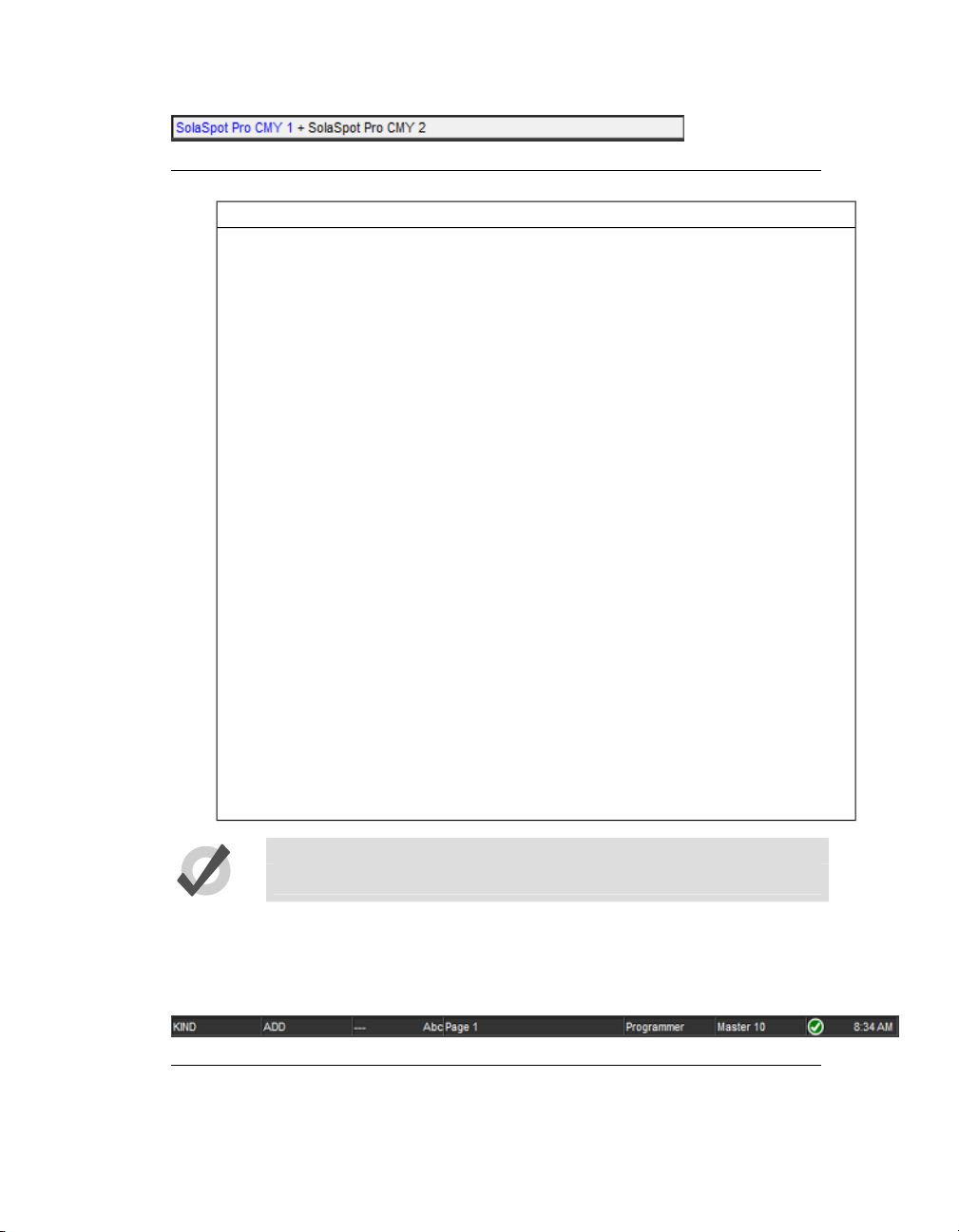
Figure 2.1. The Command Line
Section 2: Hog 4OS Fundamentals
CommentsDestinationOptionsCommandMaskSource
Position 1Record
Position 1ReplaceRecord
Position 2CopyPosition1
Position 2ReplaceMovePosition 1
Position 3RecordGroup 2
Cue 5CopyPositionCue 1Group 3
Records a position palette
to location 1 in the position
palette directory. No
source is given, so the
content ofthe current editor is assumed.
The Replaceoption(on the
Record Options Toolbar)
ensures that the new
palette replaces the previously recorded palette.
The Copycommand takes
the Position 1 palette as its
source.
This example combines using a source and a record
option.
Here Group 2 acts as a
mask for the record command, so that only fixtures
in Group 2 are recorded
into the Position 3 palette.
Here the parameter values
of fixtures in Group 3 are
copied from Cue 1 to Cue
5. The Position option applied to the copy command meansthat onlyposition parameters are included.
2.1.2
Tip
The text of the command line turns red if your syntax is not valid.
The Status Bar
To the right of the command line is the Status Bar.
Figure 2.2. The Status Bar
The Status Bar gives you basic information about the status of the console as well as
connected network items.
High End Systems22
Page 27
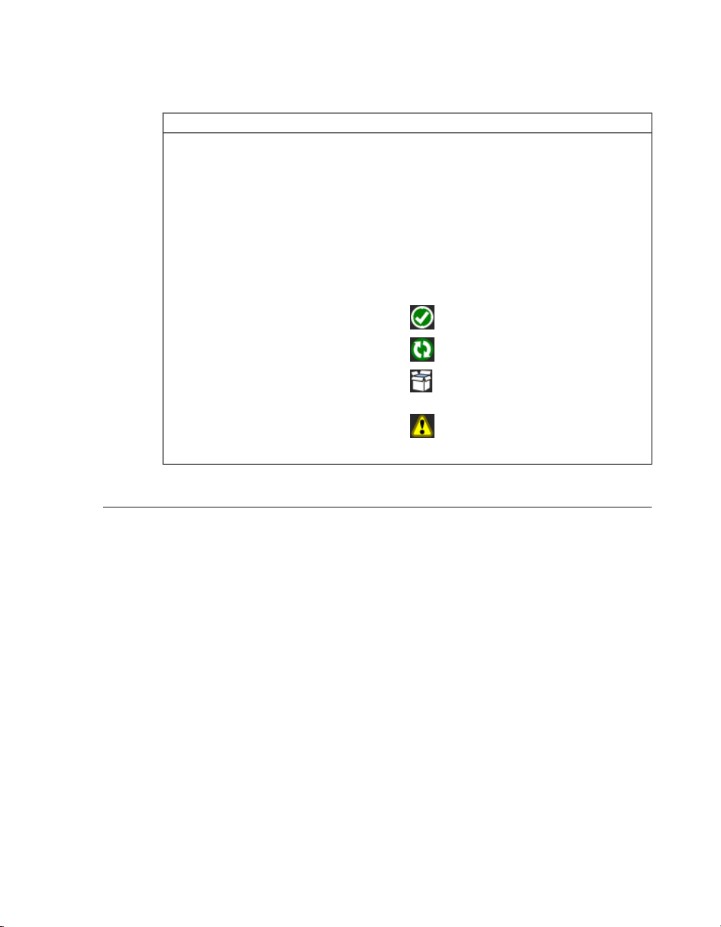
Section 2: Hog 4OS Fundamentals
Below is a list of the different kinds of data the status toolbar can show:
The Trackball mode
The current editor
The network status
ExampleDescription
--- (pointer)
POS (position)
POS, ortho (ortho mode)
Page 1The name of the current page
CMD (command key mode)Current Mode of the Function Keys
KIND (kind key mode)
Programmer
Cue 3
Master 4The currently chosen master
The network is working normally.
Consoles are syncing show data.
Connected DP8000's need a software
upgrade.
There is a problem with the network.
16:28The current time in hours and minutes.
2.2
The Graphical User Interface
In additionto theconventional command line,the Hog4OS usesa graphical user interface similar to those found on personal computers.
The advantages of the graphical user interface are far-reaching, and will become fully
apparent as you get more familiar with Hog 4OS.
Key features of the GUI are:
• You can work with on-screen controls and windows using the touch
screen or through a pointer controlled by the built in Trackball, or an
external mouse. Left-clicking the mouse is the same as touching the
screen andis usedfor selecting oractivating controls, whileright-clicking
brings up a context-sensitive range of menu options.
• The Soft Keys adjacent to the touch screens provide another method of
accessing functions, changing to match whichever toolbar is docked
along that edge of the screen.
• The graphical environment is highlycustomisable, giving youcomplete
control of the console and individual window layout. For example, you
can rearrange column headers in list windows (e.g. the Cuelist and Pro-
23High End Systems
Page 28

Section 2: Hog 4OS Fundamentals
grammer windows) to prioritise information that is most pertinent to a
specific showor user.Information displayed canalso besorted or filtered.
When a user logs out these preferences and settings are stored, and retrieved again on logging in.
2.2.1
Opening Windows
Window Management
Windows can be opened in five ways:
•
•
•
Press and hold on thetouchscreen: Press and hold onanyempty section
of the touchscreen (double click also works); this will bring up a menu
window which contains button options for convertingthe menuwindow
into a system window such as the programmer or output window. The
initial sizeof themenu window dependson where you press thescreen.
For example, pressing and holding in one of the four corners of the
screen will opens a quarter sized menu window while pressing and
holding in the middle of the screen close to the Hog 4 logo will open a
menu window that is full screen.
From a Toolbar: Some windows may have a dedicated button that can
be pressed; the Programmer, for example.
With the Open Key: To open a window using console keys, hold down
Open and press the window's associated key or button. For example:
• Open + Position : opens the Position Directory window.
• Open + List : opens the Cuelist Directory window.
• Open + Choose : opens the Cuelist window for the
chosen master.
You can also hold down the Open key to gain access the second level
of the main toolbar with buttons for many of the console's windows,
such as the Output and Parked windows.
•
From the Command Line: You can specify the window to be opened
using the command line, and then press the Open key. For example:
•
Position 5 Open : opens the editor window for Position
Palette 5.
•
Cue 4 / 8 Open : opens the editor window for Cue 8
in the cuelist on Master 4.
•
Double Pressing Keys: You can also open some windows by doublepressing the appropriate key:
• Position, Position :opens the Position Directorywindow.
High End Systems24
Page 29

Section 2: Hog 4OS Fundamentals
Tip
If you prefer not to use the double-press shortcut to open windows, then
assign the double-press time to zero to disable it: see Keys and Button Pref-
erences (p.100).
Closing Windows
Windows can be closed using the window's Close button (marked with a cross, at the
right hand end of its title bar), by pressingOpen + Backspace, or with the Close button
on the Window Control Toolbar.
Fronting, Resizing and Moving Windows
You can open as many windows as you wish, but you can only work in one at a time.
To work in a window make it the frontmost by clicking or pressing the touch-screen
within it, or use the Focus button on the Window Control Toolbar. The window's
title bar will turn blue to show that the window is frontmost; otherwise it is grey.
Windows and toolbars can be placed any where within the console's internal touchscreens, or on the (optional) external displays.
You can move and resize windows using keys and buttons, or by using the mouse or
trackball.
Using Keys and Buttons
The Window Control Toolbar sits at the top of the right-hand touch screen, and provides
a quickand easy way tomanipulate windows. Its functions arealso available askeyboard
shortcuts.
25High End Systems
Page 30
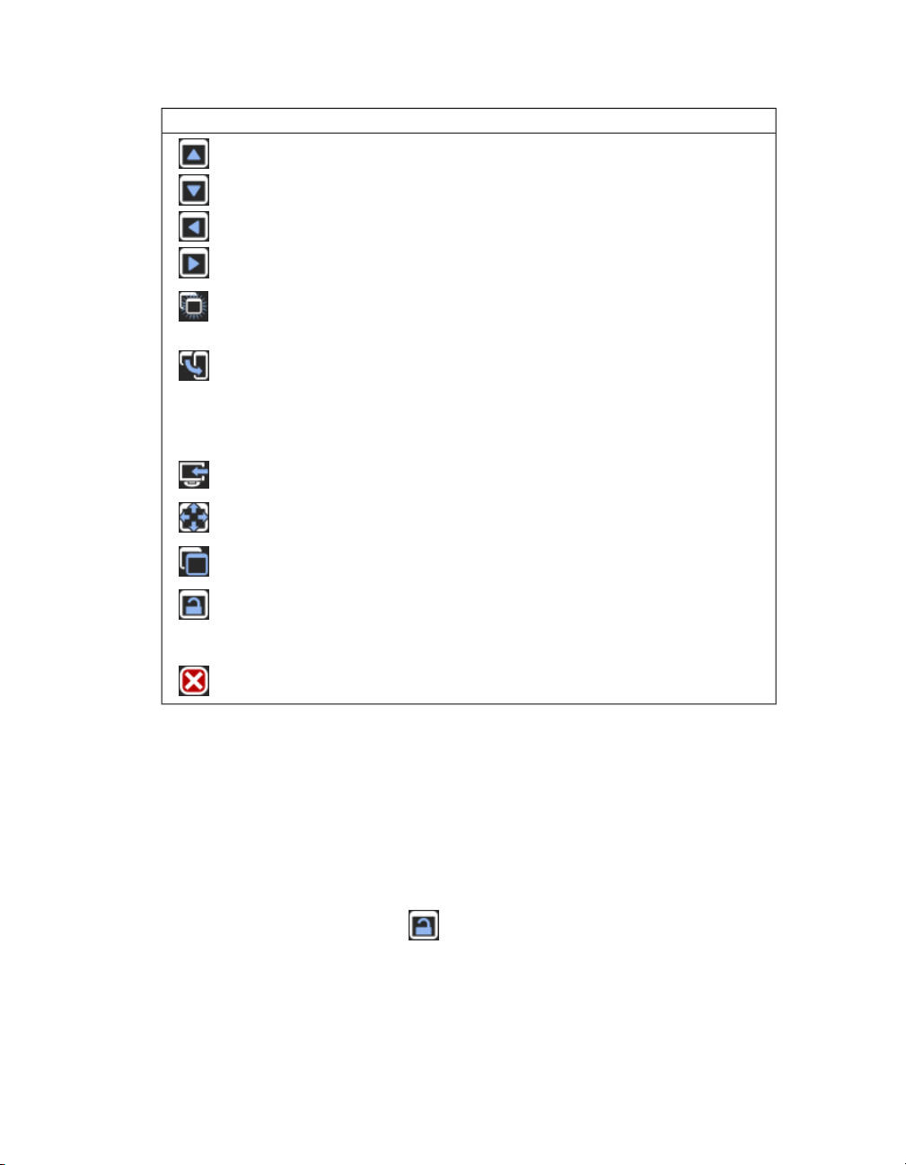
Section 2: Hog 4OS Fundamentals
Page Up, Page Down, Page Left and Page Right scroll
the currently selected window. The cursor isn't moved.
ShortcutFunctionButton
helpful when you need to view two parts of the same
window at once.
for the selected window within its current screen. The
options are full screen, and top, bottom, left and right
half and quarter screens. Holding down the Pig key
while pressing Size rotates through the options in the
reverse order.
touch-screens and external displays.
window between full screen and its previous size.
to the front.
windows to be changed bythe Trackball ormouse (but
not the toolbar buttons). Windows are unlocked when
this button is enabled.
Using the Mouse or Trackball
To move a window, click and hold on the window's top status bar whilst dragging it
to its new position. To move a toolbar click and hold its left-hand edge and drag to its
new position.
Open + [slash]Copy creates a copy of the selected window. This is
Open + [plus] or [minus]Size rotates through a range of set positions and sizes
Open + @Move Screen moves the selected window between
Open + FullMaximise toggles the size of the currently selected
Open + ThruFocus switchesbetweenwindows in turn, bringing each
Open + .The unlock button allows the positions and sizes of all
Open + BackspaceClose closes the frontmost window.
Windows can be resized by clicking and holding on corners until the resize arrow appears. You can then drag the corner to make the window bigger or smaller.
Note that you can only use the mouse or Trackball to move and resize windows if you
have unlocked them with the Lock button on the Window Control Toolbar. Keeping
the windows locked is usefulwhen usingthe touch screens, sothat you do not accidentally drag or resize windows with their title bars or borders. You can still move and
resize windows with the buttons on the toolbar.
High End Systems26
Page 31

Section 2: Hog 4OS Fundamentals
Scrolling Window Contents
When awindow's contents is too great to fitinside the window, scrollbars appearalong
the right and bottom edges of the window. You can scroll by pressing or clicking and
then dragging on the scroll bar's slider, or by pressing or clicking on the arrows at the
ends of the scroll bar.
In addition, you can scroll window contents by holding down the Open key and using
the Trackball, I-Wheel or parameter wheels to scroll.
Desktop Views
Figure 2.3. The View Toolbar
Desktop views allow you to store arrangements of windows for quick access so you do
not have to re-open and re-arrange windows to perform specific tasks. For example,
you could create a programming view that shows the group, palette and effects directories along with the Programmer window. A playback view could display the cuelist
and scene directories, and the Output window.
Desktop views are managed by the View Toolbar at the top of the left-hand touch screen
(see Figure 2.3, “The View Toolbar”) and the Views Directory (see Figure 2.4, “The Views
Directory”). You can open the Views Directory by holding down the Open key and
pressing the View button on the View Toolbar.
Figure 2.4. The Views Directory
Tip
When you create a new show, it automatically contains desktop views for
palettes, cuelists, output and the Programmer.
Recording a Desktop View
To record a desktop view using the View Toolbar:
27High End Systems
Page 32

1. Arrange the console'swindowsasyouwantthem stored inthe desktop
view.
2. Hold down the Record key and press one of the numbered buttons on
the View Toolbar.
Naming a Desktop View
To name a desktop view using the View Toolbar:
1. Press the Set key together with the appropriate button on the View
Toolbar. The Quickname window will open.
2. Enter a name, and click on OK.
To name a desktop view using the Views Directory:
1. Open + View : opens the Views Directory.
2. Select the button for the view you want to name. Make sure that the
Guard button isdepressed, otherwiseyouwill activate the view instead
of just selecting it.
3. Press the Set key. The Quickname window will open.
4. Enter a name, and click on OK.
Section 2: Hog 4OS Fundamentals
Tip
You can also assign view names, and add comments to them, in the
spreadsheet view of the Views Directory. See Desktop View Options (p.28).
Recalling a Desktop View
You can recall desktop views in two ways:
•
With the View Toolbar: located at the top of the left hand screen. The
views each have their own button, and are loaded in pages of ten onto
the toolbar. You can load the next page by pressing the Next button at
the right hand end of the toolbar, while Pig + Next loads the previous
page.
•
With the Views Directory window: press the view's button in the Views
Directory window. Make sure that the Guard button is not depressed,
otherwise you will only select the view, rather than activating it.
Desktop View Options
By default, when you recall one desktop view it replaces the previous one, so that all
windows not part of the new view are closed. However, you can set views so that they
are additive instead:
1. Open + View : opens the Views Directory.
High End Systems28
Page 33

Section 2: Hog 4OS Fundamentals
2. Select the directory's spreadsheet view.
3. Select the view's cell in the Additive column.
4. Press the Set key to toggle between Yes and No.
Figure 2.5. The Views Directory in Spreadsheet View
Deleting a Desktop View
To delete a desktop view using the View Toolbar:
1. Hold down the Delete key and press the appropriate button on the
View Toolbar.
2. Press OK to confirm.
To delete a view using the Views Directory:
1. Open + View : opens the Views Directory.
2. Check that the directory's Guard button is depressed, so that you can
select buttons within the directory without activating them.
3. Press the appropriate directory button and then the Delete key.
4. Click OK to confirm the delete.
Tip
If you prefer not to be asked to confirm the delete action, select Don't Ask
Me Again in the confirmation window. You can reenable the confirmation
by going to Setup → Preferences → Programming and selecting Confirm
before deleting directory items.
29High End Systems
Page 34

Section 2: Hog 4OS Fundamentals
2.3
2.3.1
2.3.2
Abstraction
A key advantangeto the Hog 4OSis that youdon't have to worry about the technicalities
of how each lighting manufacturer implemtents the features of their lighting fixtures
because the Hog 4OS acts as a layer between you and the lighting hardware, automatically converting ‘abstract’ ideas of intensity, colour, and so on into the specific instructions that the fixtures need, defined by their DMX protocol.
Referring to Fixtures
The Hog 4OS treats every fixture as a single entity. Every fixture is assigned a user
number that allows users to easily recall a fixture and manipulate it's feature set no
matter how manyparametersit has.Formore information on givingyourfixtures custom
user numbers , see Assigning User Numbers to Fixtures (p.115).
Hog 4OS treats conventional lights, consisting of a luminaire controlled by a dimmer,
as a special kind of fixture known as a ‘desk channel’. A desk channel has only one
parameter: intensity.
Real World Units
Fixture parameters are described as far as possible in real world units. For example,
rotation is described in degrees while chases are described in beat per minute. This
speeds upprogramming and allows fixtures ofdifferent types tobe selected and adjusted
at the same time: for example, you can assign several fixtures of different types to all
strobe at 10 Hz without having to worry about the different DMX values required by
each fixture to achieve this. Hog 4OS will give you the best possible match between
fixtures; the only limitations are those of the fixtures themselves.
2.3.3
2.3.4
Complex Parameters
Some fixtures put more than one parameter onto a single DMX address. For example,
a fixture might use DMX values in the range 0-127 for intensity, 128-250 for strobe, and
251-255 for fixture reset. The Hog 4OS separates such functions into independent parameters, sothat you do not needto rememberthe detailedworkings of a particular fixture;
in the example given above, the intensity, strobe and reset functions all appear as separate parameters, so there is no possibility of going from strobe into reset. With parameters that share a DMX address, changing the value of one will override the value of
all theothers, sincethere can onlybe one DMX value. In the case ofour example, assigning a strobe speed will override any intensity value; the console will show a ~ in place
of the intensity value to indicate that this has happened.
Interchangeable Fixtures
Any fixture already programmed into a show can be replaced by a fixture of a different
type at any time and Hog 4OS will as far as possible convert the programmed data to
High End Systems30
Page 35

Section 2: Hog 4OS Fundamentals
apply to the new fixture type. If the new fixture has more limited capabilities than the
old one, this is handled as gracefully as possible. For more on replacing fixtures, see
Changing the Fixture Type (p.132).
2.4
Tracking
All Hog 4 family consoles are tracking by default which means the Hog 4OS records
only changed cuedata intocues and scenes allowing unchanged data that wasrecorded
in previouscues and scenes to trackthrough untila change is recorded for that particular
fixture parameter.
Below is an example of how a series of cues might be seen by a viewing audience:
CBAFixture:
10050100Cue 1
5025100Cue 2
7575100Cue 3
With a non-tracking console, each value would have to be recorded into each cue as
displayed above. However, with a tracking console such as the Hog 4, the only data
that really needs to be recorded is much simpler as shown in the table below:
CBAFixture:
10050100Cue 1
100Cue 2
75Cue 3
As you can see fixture A only has to be recorded at 100% in cue 1 because that value
will track all the way from cue 1 to cue 3. On the other hand, since fixtures B and C
change value in each cue, the tracking console needs to have unique values recorded
in each cue.
When discussing the contents of a cue or the state of playback on stage, the following
terms are commonly used:
•
Hard Values / Touched Values: Values programmed into the current
cue
•
Tracked Values / Transparent Values: Values assigned
•
State: The summation of both tracked and hard-coded values in playback. The Hog 4OS automatically recalls the state of any cue regardless
of whether or not the cuelist was played in order; this allows allows the
console operator to jump around and play cues out of order while preserving the way the cue was meant to look.
31High End Systems
Page 36

Section 2: Hog 4OS Fundamentals
2.5
HTP and LTP
Taditional theater desks that are not designed to handle moving lights will work on a
Highest Takes Precedence (HTP) basis. This means that if a fixture's intensity is being
controlled by two different parts of the console, such as a playback and a submaster,
the intensitywill beat the highest ofthe two levels.Forexample, if in the playbackfixture
1 is at 50%, and in the submaster it is at 100%, then the level seen on stage will be 100%.
If the submaster isreduced to 40%, then the on-stagelevelwill be50%, becausethe level
in the playback is higher and will take precedence.
This system generally works well for non-moving light consoles, but moving lights introduce a problem. Parameters other than intensity don't have ‘higher’ and ‘lower’
values: a colour of red is not higher or lower than green, and a pan of 50% is not higher
or lower than one of 20%. Working with moving lights needs a new way to decide the
precedence, called Latest Takes Precedence (LTP).
With this system, the fixture parameters are at the value they have been most recently
assigned. In our example, moving the submaster to 40% would result in a level of 40%,
because this is the latest instruction and will take precedence. The submaster would
effectively ‘grab’ control of the parameter from theplayback.Of course,running another
cue in the playback might grab it back again.
Many moving light consoles use HTP for intensity and LTP for all other parameters. By
default, Hog 4OS uses LTP for all parameters, but you can assign individual cuelists to
use HTPfor intensities (all other parametersare still LTP); seeUsing HTP and LTP (p.298).
2.6
2.6.1
Colour Matching
Fixtures ofdifferent typesuse differentmethods to perform colour mixing. Sending the
same parameter values to fixtures of different types might produce a different colour
on eachtype. For example, sending C=50%, M=50%, Y=0%will always produce a shade
of blue, but it'll be a different blue with different fixture types.
Usually, you have to compensate for this yourself by manually creating colour palettes
by eye to produce similar colours on all fixture types. This is a timeconsuming process,
and later restricts you to using the palettes you have already set up.
The Hog 4OS's colour matching system provides a new way to choose colours, without
these problems.
Colour Models
Traditionally, colour mixing fixtures use the CMY (Cyan, Magenta, Yellow) system to
uniquely define each colour they can produce. With the increasing popularity of LED
fixtures, the RGB (Red, Green, Blue) system is also becoming more common. These two
High End Systems32
Page 37

Section 2: Hog 4OS Fundamentals
systems are called‘colour models’. Any colour can be represented equally wellbyeither
of these two colour models - they are just different ways of conveying the same information. Many other colour models exist, perhaps the most useful of which (for lighting
control, anyway) is the HSI (Hue, Saturation, Intensity) system:
Hue: This is the term used to specify the colours position in the possible
range a colours, from red, going through yellow, green, cyan, blue and
magenta, and finally returning to red. As the range ‘wraps around’, you
can visualise it as a circle with the colours positioned around the edge,
with red at the top, green at the lower right, blue at the lower left, and
the intermediate colours in between. The angle between 0 and 360 degrees specifies the hue of the colour: red has a hue of 0 degrees, yellow
has ahue of 60 degrees, and cyan has a hue of180degrees; see Figure 2.6,
“The HSI Colour Wheel”.
Saturation: This is how ‘strong’ or ‘pale’ the colour is. Palecolours have
low saturations, while strong colours have high saturations. Saturation
is specified as a percentage between 0%(white) and 100% (the strongest
possible saturation).
Intensity: This is simply a measure of how much light is being emitted,
from 0% (black) to 100% (the brightest possible). This is identical to the
dimmer control on most fixtures.
Figure 2.6. The HSI Colour Wheel
With these three pieces of information (hue, saturation and intensity), every possible
colour can be represented. As most fixtures already feature a dimmer to control the intensity, it is only necessary to specify the Hue and Saturation to uniquely represent any
colour.
33High End Systems
Page 38

The Hue and Saturation of White Light
White is defined as the colour with 0% saturation; the hue doesn't matter. However,
while tungsten and arc lamps both produce ‘white’ light, when you compare them side
to sidetheir coloursare considerably different.The tungsten lamp has a ‘warmer’ colour
with a higher red and yellow content, while arc lamps usually have a ‘cooler’ light with
more blue in it. One version of white is not more ‘correct’ than the other, so either may
be chosen to be the reference point depending on the situation. In a theatrical environment where tungsten sources are more common tungsten white is likely to be most
appropriate base. In other environments predominantly using arc sources, it will be
more convenient touse arc white;for information on changing the white point,see Using
Colour Matching (p.160).
Section 2: Hog 4OS Fundamentals
2.6.2
The Colour Matching System
The Hog4OS's colour matching systemis basedon afixture librarythat contains colour
calibration data for the fixture types in use. This calibration ensures that fixtures of different types can easily be assigned to the same colour, including to a chosen definition
of ‘white’. It can also be used for fixtures that have not been calibrated, but the colours
that will be produced may not match the colours from fixtures that do have calibration
data.
You can choosecolours using the parameterwheels toassign cyan, magenta andyellow
values or hue and saturation values, or you can use the on-screen visual colour picker;
see The Colour Picker (p.160).
It ispreferableto program using Hueand Saturation whenever possible. The advantages
are:
• Selecting colours using Hue and Saturation or the colour picker will
produce the same visual colour output on all calibrated fixture types.
• You can use fanning and effects on Hue and Saturation to produce attractive looks quickly.
• When you use Hue and Saturation to pick a colour, Hog 4OS will automatically use the best possible DMX value settings for each fixture type
to achieve maximum light output from each fixture.
• You can crossfade from a saturated red to asaturated green without the
saturation changing. The crossfade will work through all the saturated
colours between red and green, rather than taking an unexpected path
to get there, as can happen when using CMY programming.
• Crossfades between colours recorded using Hue and Saturation will
remain matched on all fixtures through the progress of the crossfade.
This produces a better, more even-looking colour crossfade.
Tip
It is strongly recommended that you do not change between the HSI and
CMY systems within a show.
High End Systems34
Page 39

Section 2: Hog 4OS Fundamentals
2.7
Palettes and Directories
Palettes help to simplify the programming process by allowing pre-defined lighting
‘elements’ to be created and then used as required. Once you have created a palette,
such as a particular set of position settings with moving lights, you can recall those
settings instantly, and record them into cues. Palettes are stoed in windows called directories.
A great advantage of palettes is that when you record a cue using the palette, the cue
contains a reference to the palette, rather than the parameter values that the palette
contains. If, later, you change the palette then all cues that have been recorded using
the palette are also changed. This is especially useful if, for example, the position of a
piece of set on stage is moved, and moving lights have been programmed to light it.
The palette can be updated once to accommodate the change, rather than in every cue.
For more information, see Palettes (p.177).
Palettes allow intensity, position, colour and beam parameters to be recorded as easily
accessible ‘building blocks’ to be used when programming. Palettes are storedin classified directories. For general information on working with directories.
When you use a palette to assign parameter values in the Programmer, and then record
the contents of the Programmer as a scene or cue, the Hog 4OS records a reference to
the paletterather thannumerical values for the parameters.During playback, the console
refers to the parameter values stored within the palette when outputting cue data to
the stage.Because of this referencing, when you modify a palette's content, the cues and
scenes that were programmed using it will,in effect,be automatically updated with the
new values. The palette is said to be ‘referenced’ in the cue. This is a very powerful
feature that allows you to make global changes to the show very simply and quickly,
rather than having to re-program every cue individually.
If you wish to make a palette that is just a programming tool, where later changes to
the palette will not cause cues, scenesand other palettes recordedwith it to be updated,
then you can use directpalettes. With directpalettes,actual parameter valuesare placed
into cues, rather than references. See Direct Palettes (p.186).
Tip
Hog 4OS can automatically generate a useful set of palettes based on the
fixtures inyour show: see Cr eating Palettes and Groups Automatically (p.133).
Directory windows give you quick access to groups, palettes, scenes, cuelists and so on,
and they all work in essentially the same way.
35High End Systems
Page 40

Section 2: Hog 4OS Fundamentals
Figure 2.7. A Typical Directory
Figure 2.7, “A Typical Directory” shows a typical directory. The main part of the window
is filled with large buttons, used to access the group, palette, scene, cuelist or page, as
well as displaying their names and some other key information:
DescriptionApplies ToDisplay
Palettes. . C .
Palettes
Palettes
Palettes
Palettes
Cuelists
Shows the parameter types recorded in the palette.
I = intensity, P = position, C = colour, B = beam, E =
effect, T = time. See
Recording Palettes with Kind Masking (p.183).
The palette is a direct palette. See
Direct Palettes (p.186).
The palette contains references to other palettes.
See Reference Palettes (p.186).
The palette is the Highlight Palette. See
Customising Highlight (p.275).
The palette is the Lowlight Palette. See
Customising Highlight (p.275).
The cuelist is a chase. See
Using a Cuelist as a Chase (p.312).
The cuelist has timecode active. See MIDI (p.353).Cuelists
Cuelists
Pages
Pages
The cuelist has clock triggers that are enabled. See
Clock Triggers (p.242).
The page is the template page. See
The Template Page (p.332).
The page has a Restore Activity macro defined. See
Restoring Activity When Changing Pages (p.328).
High End Systems36
Page 41

Section 2: Hog 4OS Fundamentals
You can rename the selected button (with the red border) by pressing the Set key. You
can also hold Set and press any button to rename it.
At the top of the window there are four buttons common to all directories:
Switches to a spreadsheet view, allowing you to edit attributes of the items
in the directory such as their names. See Spreadsheets (p.40) and
Figure 2.8, “A Typical Directory in Spreadsheet View”.
Reports. This allows you to print the contents of the window.
Configure. This allows you to control various aspects of how the directory
window displays information.
Guard
When this is depressed, pressing the directory's buttons does not activate
them. Instead it selects the item and inserts it in the command line.
2.7.1
Figure 2.8. A Typical Directory in Spreadsheet View
Tip
You can override the effect of the Guard button by holding down the Pig
key while pressing a directory button.
Automatic Naming of Directory Items
When you create or copy a directory item, the console automatically generates a name
for the new item.For example, ifyou havetwo position palettes and them create a third,
the new one will be recorded into location 3 in the directory and named ‘Position 3’. If
you then copy this position palette, the copy will be recorded into location 4 in the directory and named ‘Copy of Position 3’.
37High End Systems
Page 42

Section 2: Hog 4OS Fundamentals
You can customise how the console automatically generates these names in the Default
Naming pane of the User Preferences window; see Figure 2.9, “The Default Naming pane
of the User Preferences window”. To open the Default Naming pane:
• Setup → Preferences → Default Naming
To customise the generated labels:
1. Click or press on the textbox for the required type of directory (group,
intensity, position, and so on). Labels for when the new directory item
is createdbyrecording or bycopyingare handledin separate text boxes.
2.
Set, [new label text], Enter : type in the label you want.
3. Alternatively, click or press on the arrow at the right hand end of the
text box to get a list of useful labels. Click on the one you want.
You can use special tags to have the console insert text into the name for you, according
to the directory name and the location in the directory:
•
&d: the directory name
•
&D: the directory name (dynamic)
•
&n: the directory number
•
&N: the directory number (dynamic)
•
&o: the original text. This is used when a directory item is copied; the
original text is the name of the item that has been copied.
2.7.2
Lowercase tags are resolved once only, when the name is applied, while uppercase tags
remain unresolved until the name is displayed (known as ‘dynamic’). So, pressing Set
and entering the name of colour palette 3 as ‘&d &n’ will assign the name to be ‘Colour
3’. If you assign the name to be ‘&D &N’, the name will also be assigned to ‘Colour 3’.
The difference is that moving this palette to position 4 will automatically correct the
name to ‘Colour 4’.
Colour Coding Directory Items
Each directory window allows for unique colour coding of each button within the directory. The default colour for new directory items is standard grey. When you copy a
directory item, the console will automatically copy the directory item's custom colour
as well see Figure 2.10, “Directory Item Colour”.
Note: The playback bar, view toolbar, and commands keys automatically reflect the
color-coding of the objects that they display. Color-coding for these objects can only be
changed in the directory and the is thus reflected everywhere that object is shown.
To customise a directory item in button view:
1. Using the mouse, right click on the directory button to open the right
click menu.
High End Systems38
Page 43

Section 2: Hog 4OS Fundamentals
Figure 2.9. The Default Naming pane of the User Preferences window
Figure 2.10. Directory Item Colour
2.
Click on one of the 15 options shown in Figure 2.11, “The Preset Colour
Options” to assign the directory item this colour.
3. Alternatively, click on Choose to select a custom colour from a colour
wheel or click None to select the standard grey colour. Click on Auto
to have palettes in the Colour directory automatically determine the
39High End Systems
Page 44

Section 2: Hog 4OS Fundamentals
button color based upon the dominate colour value recorded in the
palette.
To customise a directory item in spreadsheet view:
1. Select the Colour cell and press Set to open the colour selection menu.
2. Click on one of the 15 preset colours to assign the directory item this
colour.
3. Alternatively, click on Choose to select a custom colour from a colour
wheel or click None to select the standard grey colour. Click on Auto
to have palettes in the Colour directory automatically determine the
button color based upon the dominate colour value recorded in the
palette.
Tip
You can select multiple buttons or cells by clicking and dragging to assign
the same colour to multiple items.
2.8
Spreadsheets
Similar to Excel spreadsheets, many windows in the Hog 4OS such as the programmer,
output window, and cue editors are presented as spreadsheets.
All of the spreadsheets in the Hog 4OS share a common set of features:
•
To resize a spreadhseet column: Place the cursor over the right-hand
edge of the column header. The cursor will change to a double-ended
arrow. Click and drag to resize the column.
•
To move a spreasheet column: Click and drag on the column header.
High End Systems40
Page 45

Section 2: Hog 4OS Fundamentals
Figure 2.11. The Preset Colour Options
•
To hide a spreadsheet column: Right-click on the column header, and
choose Hide.
•
To show a hidden spreadhseet column: Right-click on a columnheader,
and choose the name of the column from the menu.
•
To sort the spreadsheet: Right-click on a column header and select Sort
to sort the spreadsheet by the values in that column. Select Sort again to
the reverse the direction of the sort. Youcan alsoright-click ona column
header andselect Sub-sort to assigna secondlevel of sorting.For example,
if you sort the Fixture window by fixture type, and sub-sort by Patch,
then allthe Desk Channels willbe shown grouped together, in the order
of their patch address.
•
To select all the cells in a spreadsheet column: Double-click on the
column header at the top of the spreadsheet.
•
To select a single spreadsheet cell: Click or press in the cell. You can
use the cursor keys below the Trackball to change which cell is selected.
If the cell is editable, it will have a red border.
•
To select a range of cells in a spreasheet: You can click or press and
then drag across a range of cells to select them all. Alternatively, you
can click in the first cell, press and hold Thru, and click in the last cell;
this is useful if you want to select a large range and need to scroll the
window.
•
To edit the contents of cells in a spreadsheet: Click or press in the cell
and press the Set key, or double-click in the cell. Type in the new value,
and press Enter. This works for both a single selected cell and a range.
Cells that are editable have a red border when selected. Cells labeled
Colour in cuelists and scenes will open the colour selection dialog to
allow you to colour code the cell.
41High End Systems
Page 46

Section 2: Hog 4OS Fundamentals
2.8.1
Compact Mode
In editor windows such as the Programmer, you can use compact mode to save space
and get more information onto the screen without having to scroll; see Figure 2.12, “A
spreadsheet with andwithout Compact Mode”. In compact mode,fixtures only have columns
for theactual parameters that theyhave, rather thanfor all the parameters of any fixture
in the editor. The console uses the display space more efficiently by having multiple
columns for fixture types with few parameters, such as desk channels.
You can toggle compact mode on and off with the Compact button in the window's
toolbar.
Figure 2.12. A spreadsheet with and without Compact Mode
2.8.2
Note that you cannot sort a spreadsheet that is in compact mode.
Aggregation
In windows such as the Programmer, it is often useful to keep fixtures of the same type
together; this is known as ‘aggregation’. The spreadsheet effectively becomes a list of
fixtures in fixture type order, with headings in the list separating each fixture type; see
Figure 2.13, “A Spreadsheet with Aggregation Turned On”.
To use aggregation:
1. Make sure the spreadsheet is sorted by Fixture Type: right click on the
Type column and select Sort. If the Type column isn't visible, right click
on any column heading and select Type.
2.
Press to open the Configuration window.
3. Select Enable Aggregation.
4. Click on OK.
High End Systems42
Page 47

Section 2: Hog 4OS Fundamentals
Figure 2.13. A Spreadsheet with Aggregation Turned On
Note that aggregation is always on if the spreadsheet is in compact mode; see Compact
Mode (p.42).
Tip
Aggregation is turned on by default in all editors, such as the Programmer.
Collapsing Aggregated Sections
You can collapse aggregated sections to hide all the rows in that section; see Figure 2.14,
“An Aggregated Spreadsheet With Collapsed Rows”. To collapse an aggregate section, right
click the black heading bar and select Collapse.
To expand the aggregationsection again, right click the section's black heading bar and
select Expand.
43High End Systems
Page 48

Figure 2.14. An Aggregated Spreadsheet With Collapsed Rows
Priority of Aggregated Sections
Section 2: Hog 4OS Fundamentals
You can change the position of an aggregation section in the list by altering its priority.
Raising a section's priority will make it appear nearer the top of the spreadsheet.
To move an aggregate row up or down in priority, right click the section's black header
bar and then select Raise Priority or Lower Priority.
Jumping Between Aggregated Sections
You can quickly bring aggregated sections into view using the Jump Toolbar located
on the upper right of a spreadsheet window, see Figure 2.15, “The Jump Toolbar”. This
has a button for each aggregation section; clicking a button will scroll the list to bring
the section into view.
Figure 2.15. The Jump Toolbar
High End Systems44
Page 49

Section 2: Hog 4OS Fundamentals
To enable the jump toolbar:
1.
Press to open the Configuration window.
2. Select Enable Jump Toolbar.
3. Click on Apply.
Tip
The jump toolbar is turned on by default in all editors, such as the Programmer.
2.8.3
2.9
Cut, Copy and Paste
You can copy and paste the contents of selected cells:
• Right-click, and select Copy or Paste from the contextual menu.
Or:
• Pig + Copy : copy.
• Pig + Record : paste.
Editors
Editors are windows where you can view and assign the parameter values of fixtures.
The most important editor in the Hog 4OS is the programmer which acts as the default
active editor for all parameter changes when no other editors are open or active. Individual cues,scenes, and palettescan all beopenned ineditors. Editing parameter values
works in essentially the same way for all of editors; see Selecting Fixtures and Modifying
Parameters (p.143).
Figure 2.16. A Typical Editor
45High End Systems
Page 50

Section 2: Hog 4OS Fundamentals
You can openan editor window for any cue, scene or palette by holding down the Open
key andselecting it from its directory window. Alternatively, you can use the command
line:
•
Cue 1 Open : opens an editor for Cue 1 and makes it editable.
2.9.1
Editor Window Controls
The main part of an editor window shows the fixture parameter values in aspreadsheet
view, with each row representing a single fixture; see Spreadsheets (p.40).
At the topof the window thereare three toolbars with buttons:the EditorValues Toolbar
toolbar, the Editor Toolbar, and the Jump Toolbar. The following sections describe the
buttons that are common across all editors; some editors have additional buttons that
are specific to that type of editor, and these are described in the relevant part of the
manual.
The Editor Values Toolbar
The Editor Values Toolbar has buttons for: Value, Fade, Delay, Path, Size, Rate, Offset,
Length, Table, andN Shot.Use these buttons to display the different kinds ofinformation
associated with the fixture's parameters; see Fade, Delay, and Path (p.230).
The Editor Toolbar
The Editor Toolbar has the following buttons:
PurposeButton
Press this to make the contents of the editor editable, rather than just to
view it. Instructions given to the command line, or using the parameter
wheels and I-Wheel, are directed to the editable editor.
In cue editors, press this to see all the parameters that will appear on
stage, including those that have tracked through from earlier cues in the
cuelist. With Show State deselected, only the hard values actually recorded in the cue are displayed.
Press Show Palettes to see the palette name, rather than the parameter
value; see Palettes (p.177).
Press this to have parameter values changed in this editor fade rather
than snap onto stage; see Fade Changes (p.278).
Press this to toggle compact mode on and off. Compact mode fits more
information into the editor without having to scroll. However, the column
for a particular parameter won't necessarily be aligned across different
fixture types, so sorting is not possible.
Reports. This allows you to print the contents of the window.
Configure. This allows you to control various aspects of how the editor
window displays information.
High End Systems46
Page 51

Section 2: Hog 4OS Fundamentals
The Jump Toolbar
The Jump Toolbar has a button for each type of fixture currently in the editor, allowing
you to quickly jump to the parameter values for that type of fixture. The Jump Toolbar
only appears if aggregation is turned on; see Aggregation (p.42).
2.9.2
Changing Parameter Values in the Editor
To make changes to the contents of an editor, you need to have its Edit button selected.
You can have up to eight editors open, but only one can be editable at a time, and the
parameter wheels, I-Wheel and commandline alloperateon thecontents ofthe currently
editable editor. If you have several editors open at once, you can use the Edit button to
determine which one you are controlling (even if it is not the frontmost window) or to
‘lock’ the editor to prevent accidental changes.
Tip
When you open an editor, all the fixtures within the editor are automatically
selected. This aids quick editing of cues or palettes. You can also deselect
the Select All on active editor option under the Misc tab of the preference
window sothat editors can be opened and closed without changing fixture
selection.
After you have finished editing a cue, scene or palette, press the Update key to apply
changes. Until you do this, changes won't show up if you run the cue or scene, or use
the palette. The exception to this is when you are working in the Programmer, when
the Update key will perform the Auto Update function; see Auto Update (p.276).
If you hold down the Update key, the Update Toolbar will appear. This allows you to
select which parameter types are recorded, whether changes should track forwards,
and whether references should be allowed when recording palettes. See Stopping Values
from Tracking Forward (p.212) and Reference Palettes (p.186).
If you close the editor without updating, you will be asked whether you want to save
or discard the changes, or cancel the closing of the editor.
2.10
Tip
The name of the current editable editor is shown in the Command Line
Toolbar. By default, it is the Programmer. The name of the item being edited
appears in the title bar of the editor window.
Modifier Keys
The Hog 4 family of consoles all share a common set of useful multi-purpose modifier
keys that when held down extend the base functionality of other keys and wheels on
the front panel similar way to a Shift or Control key works on personal computers.
47High End Systems
Page 52

Section 2: Hog 4OS Fundamentals
There are several modifierkeysbut the coremodifier keys inthe Hog 4OSare Pig, Open,
Delete, Backspace, Set, Cue and Move.
Pig Key Modifier Examples:
1. Pig + I-Wheel : Changes wheel to proportional intensity mode.
2. Pig + Move : Pastes information into the selected location.
Key & Button Combinations (p.425) has a full list of commands that use the Pig key.
2.11
Undo and Redo
The Undo button found on the Main Toolbar is similar to the undo command found in
computer applications, allowing the user to work back through the last commands
entered by the user, undoing them each time the button is pressed. In the Hog 4OS the
undo key is global, working back through operations in chronological order, and you
can go back all the way to the point at which you logged on to the console (generally,
this is when you started the console up).In cases where multiple consolesare networked
together the undo task will only undo actions of the local desk.
Pressing the Pig button,together with the Undo button, willredo the last undoneaction.
Again, if you have gone back through several undos, you can redo repeatedly until you
get back to the most recent action.
The undo and redo feature works onyour show data, but generally not onother things.
Undo is not available for:
• Changes to the fixture selection in the Programmer. However,the selection may change as a side effect of an undo action.
• Changes to Control Panel settings, and other things not directly related
to your programmed show.
• Changes to window positions and views, and the like.
If undo is not available, you will always be asked to confirm important changes before
they take place.
High End Systems48
Page 53

Section 2: Hog 4OS Fundamentals
2.12
2.12.1
The File Browser
You can browse and organize several different kinds of system files in the File Browser
pane of the Show Manager window; see Figure 4.2, “The Show Manager Window”. On
the left is a list of the main console folders and the console's drives. Clicking on one of
these will display its contents in the right hand list.
The browser shows the name, description,and creation date and time of the file, as well
as the version number of the library used to create the show in parentheses. If the show
is marked as modified, then the library has been altered through a library merge.
Moving, Copying, Deleting and Renaming Files
To move a file:
• Drag anddrop files to destinations inthe left hand folderlist. Generally,
you will find dragging with the mouse or Trackball much easier than
using the touchscreen.
To copy a file:
• Drag and drop files while holding down the Pig key (or the Control
key on an external keyboard).
To delete a file:
• Right-click on the file and select Delete from the contextual menu. You
will be asked to confirm the action.
2.12.2
To rename a file:
• Right-click on the file and select Rename from the contextual menu.
Type in the new name and press Enter.
Tip
You can also copy and paste files by right-clicking on them and selecting
Copy or Paste from the contextual menu.
Creating New Folders
You can create sub-folders in the Shows and Libraries folders to help organise your
work:
1. Click on the folder you want to make a new folder in.
2.
Click on the button.
3. Enter a name for the folder and press Enter.
49High End Systems
Page 54

Note that you cannot create folders on a CD-ROM.
Tip
You can also create a new folder inside an existing one by right clicking on
it and using the contextual menu.
Section 2: Hog 4OS Fundamentals
2.12.3
2.12.4
Ejecting Disks
You cannot eject a disk in the console' CD drive if it is in use. Before ejecting, make sure
that you don't have the disks folder selected in the File Browser. If a disk will not eject,
check that you are not browsing its contents elsewhere, and that the console is not currently accessing it.
Burning files to CD
To burn files onto a recordable CD:
1.
Setup → Shows → CD Burning : see Figure 2.17, “The CD Burning pane of
the Show Manager window”.
2. Select a file to be copied in the left-hand list, and click the Add to CD
button to move it to the right-hand list. You may be asked to archive
the file before adding it to the list; click OK to agree to this.
3. Repeat for all the files you want to copy to the CD.
4. Insert a recordable CD into the CD drive, located under the console's
front wrist rest.
5. Press the Burn button, and then the Start Burn button in the CD Burning
window. The window will show the progress of the writing operation.
High End Systems50
Page 55

Section 2: Hog 4OS Fundamentals
Figure 2.17. The CD Burning pane of the Show Manager window
Tip
You can use drag and drop to move files to the CD Master list. Note that
files will always be copied, not moved.
51High End Systems
Page 56

Page 57

Section 3: Setting Up the System
3.1
3.1.1
Setting Up the Console
Starting Up the Console
To power on and start up the console plug one end of a standard IEC power cable into
any 100-220 VAC power source and plug the other end into the console's dedicated IEC
powerport and then turn the power switchon theback ofthe console tothe onposition.
Make sure that any external bootable media such as bootable USB flash drives or CDs
are removed from the console before booting as the console may try to boot to that
media instead of to the installed operating system. When the console has finishing
booting you will see two windows: the Hog 4OS splash screen and the Hog 4OS start
screen. Your console is now ready for operation.
Important
Using anungrounded power source leads toa greater risk of shock andmay
cause the motorized faders on the Hog 4 and Full Boar 4 consoles to not
function properly. Always make sure that the power source for your console
is properly grounded.
3.1.2
Figure 3.1. Start Screen, your console is ready to use
Adjusting the Date and Time
The console has a builtin clock which is shown at the farright end of the command line
toolbar. To change the console's date, time, and time zone open the Control Panel and
53High End Systems
Page 58

Section 3: Setting Up the System
navigate to the Time and Date tab. To change the format in which the console displays
the date and time in your show file open the Preferences window and navigate to
theAppearance tab. The format preference is stored in the show file and will change
based on which show file you load.
Note: In order to permanately store changes made to the time and date of the console
you must restart the Hog 4OS or properly shutdown/reboot the console. Simply
switching the console's power switch off/on will result in any time and date changes
being lost.
3.1.3
3.1.4
Calibrating the Touch Screens
The touchscreens may occasionallyneed to be calibrated. To recalibratethe touchscreens
before launching a show, select the Touchscreens button in the Start window. Touch
each target as it appears sequentially; see Figure 3.2, “The Calibration Screen”. After the
calibration sequence is complete, press Enter. You can press the Set key to start the
process again if necessary. You can also calibrate the touch screens at any time while
loaded in a show by pressing the Calibrate Touch Screens button in the Displays pane of
the Control Panel. Users can also start the touchscreen calibration at any time on their
console by holding the Set key and pressing the encoder wheel button below the first
main encoder wheel.
Figure 3.2. The Calibration Screen
Adjusting the Touschscreen LCD Backlight
You can adjust the brightness of the built-in touchscreens by adjusting theLCD backlight
settings of the console (Hog 4 and Full Boar 4 only). To adjust the LCD backlight hold
down the Setup key and adjust the parameter wheels labelled Left Backlight or Right
Backlight.
Tip
If you find the graphics on the screens are too bright, you can change the
console's colour scheme to a darker one in Setup → Preferences → Appear-
ance.
High End Systems54
Page 59

Section 3: Setting Up the System
3.1.5
3.1.6
Changing the LCD Backlight Timeout
The backlights that illuminate the console's primary touch screens switch off automatically after a period of time if the console is idle. You can adjust the amount of time the
backlights willwaitbeforeswitching offin the Appearance pane of the User Preferences
window:
1. Setup → Preferences → Appearance
2. Adjust the Backlight Off time located at the bottom of the pane, either
by pressing the arrows to increment or decrement the value, or by
clicking on the value, pressing Set and typing in a new value.
3. Select OK to apply and close.
Tip
Once the Hog displays are asleep you can wake them up by pressing any
key. It is a good ideato use the Pig key as this will preventyou from accidentally changing any data within the show.
Adding External Monitors
You can attach three external displaysto the Hog 4using standard DVI orVGA connectors.
To use external displays, you must enable them and set the screen resolution in the
Displays pane of the Control Panel:
3.1.7
• Setup → Control Panel → Displays
You will need to restart the console to enable the external monitors.
NOTES:
The Full Boar 4’s DVI-D monitor output connections do not support analog output to
VGA displayssuch as those featured onthe olderFull Boar 3playbackand programming
wings.
The RackHog 4's VGA monitor output is not supported. Although some VGA monitors
may work on this port it is advised to only use the DVI-D output on the back of the
RackHog 4.
Adding External Touch Screens
External USB touch screens are supported on the Hog 4, Full Boar 4, and Road Hog 4
consoles. When an external touchscreen is required High End Systems recommends
using Master Wing 4 or Playback Wing 4 for the greatest level of compatability and integration. Additionally Hog 4 OS consoles are compatible with touchscreen monitors
listed below:
55High End Systems
Page 60

Section 3: Setting Up the System
facturer
ELO
ELO
ELO
ELO
cuTouch
ET1229L
cuTouch
ET1215L
cuTouch
ET1725L
ET1519L
SizeModelManu-
12"Ac-
Part Number
All Part
No.
E43253212"Ac-
E23207015.6"iTouch
Video
Notes
VGA
Only /
Must
use
VGAto-DVI
adapter
with
for use
with
Full
Boar 4
VGA
Only /
Must
use
VGAto-DVI
adapter
with
for use
with
Full
Boar 4
VGA/DVIE10304717"Ac-
VGA
Only /
Must
use
VGAto-DVI
adapter
with
for use
with
Full
Boar 4
High End Systems56
Page 61

Section 3: Setting Up the System
facturer
ELO
ELO
IC
ET1919L
latouch
Plus
ET2201L
SizeModelManu-
Part Number
E17602618.5"iTouch
VS1502323"TD2340VIEWSON-
Video
Notes
VGA
Only /
Must
use
VGAto-DVI
adapter
with
for use
with
Full
Boar 4
VGA/DVIE10776622"Intel-
VGA &
HDMI /
Must
use
HDMIto-DVI
adapter
with
for use
with
Full
Boar 4
To connect anexternal touchscreen to your console connect your touschscreenmontor's
DVI or VGA video signal cable to one of the video output connections on the back of
the console. Navigate to the displays tab of the control panel and use the appropriate
drop down menu to set the resolution of the external monitor and hit apply. You will
then be prompted to restart the console. After the console has restarted plug in the
touschscreen monitor's USB cable to any one of the USB ports on the console. Once
plugged in the touchscreen will automatically be detected and begin working but may
need to be calibrated; see Calibrating the Touch Screens (p.54).
3.1.8
Keyboard
Using an External Keyboard
You canconnect anexternalkeyboardto the consolevia the console's USB ports.Choose
a keyboard model, and assign the keyboard layout according to the language of the
keyboard you have connected, in the Keyboard pane of the Control Panel.
57High End Systems
Page 62

You can adjust the timings for Repeat Delay, Repeat Period, and Double Press in the
Key Timings pane of the User Preferences window.
Tip
Youcan usean external keyboard to control many of the console's functions,
as well as entering numbers and text; see Keyboard Shortcuts (p.465).
Using the On-screen Keyboard
You can use the on-screen keyboard to enter text when an external keyboard is not
present; see Figure 3.3, “The On-screen Keyboard”. When prompted to insert text, press
the Set key to launch a touch-screen keyboard. You can use the Pig key as a 'shift' for
uppercase characters. Press the Enter key when you have finished typing.
To close the on-screen keyboard without making anychanges, press Set instead of Enter.
Section 3: Setting Up the System
Figure 3.3. The On-screen Keyboard
3.1.9
Using an External Trackball
Trackball
External USB trackballs can be connected to the console via the console's USB ports.
Most external USB trackballs are supported only as an external mouse with left and
right click capabilities however a select set oftrackballs (listed below) are fullysupported
as functional Hog 4 OS trackballs (support for all four trackball buttons and support
for the use of the trackball in both pointer and POS mode):
Kensington Expert Mouse (Model K64325)
Kensington Orbit Wireless Mobile Trackball (Model K72352US) - (note: does not have
top left and top right buttons)
Kensington SlimBlade Trackball (Model K72327US)
3.1.10
Shutting Down and Restarting the Console
To properly shut down or restart the desk, select Setup → Quit. The Quit button is on
the righthand end ofthe Setup ToolbarAfter press the quitbuttonthe ShutDowndialog
will open (see Figure 3.4, “The Shut Down Dialog”), with the following options:
High End Systems58
Page 63

Section 3: Setting Up the System
Figure 3.4. The Shut Down Dialog
•
Shut Down: shutting down will turn the Hog console off completely.
•
Restart Console: restarting is likeshutting theconsole down and turning
it on again, and will take you to the Start window.
•
Log Off: logging off will close your current desktop, Programmer and
output screens, as well as closing the current show file. The console remains powered up and running, and returns to the Start window.
•
Cancel: cancels the quit command.
In all cases your show data is automatically saved to disk.
3.1.11
Locking the Console for Access
Consoles can be locked for access at any time by hitting the setup key on the console
front panel and then pressing the lock button on the quit toolbar. Consoles can also be
locked remotely by enabling the "lock local access" button under the security tab of the
console settings window for the console on the network you wish to lock.
Figure 3.5. The Lock Button on the quit toolbar
When the console is locked the user cannot access any part of the show file or change
any dmx output to the stage. To unlock the console enter the PIN code you have setup
for your console using the touch screen, the numeric keypad on the front panel, or an
external keyboard.
59High End Systems
Page 64

Section 3: Setting Up the System
Figure 3.6. The Lock Window Requesting Pin
By defaultthe lock code for consolesis 1234. To change the lock PIN codefor the console
open the network window, right click on the console you want to change the settings
for, click onsettings, andnavigate to thesecurity tab.Change thePIN codeto the desired
value and hit apply.
Figure 3.7. Security Settings Tab of Console Settings Window
If you forget the passcode andare lockedout ofthe console you will need to powercycle
the console and relaunch the show in order to regain access to the show. Lock pin codes
are stored per show and per console.
High End Systems60
Page 65

Section 3: Setting Up the System
3.2
3.2.1
3.2.2
DMX Processor 8000 Setup
To begin setting up your DMX Processor 8000 plug in mains power at any voltage
between 100 and 240V AC. The DMX Processor 8000's most fundamental settings are
available using the built in front panel menu system.
To navigate through the front panel menu system of the DMX Processor 8000:
Move the cursor through the options backwards.
Select the option currently highlighted by the cursor.
Move the cursor through the options forwards.
Setting the Net Number
The net number is displayed on the main screen of the DMX Processor in the top righthand corner. To assign the net number:
1. Main → Network : navigate to the Network Configuration screen.
2. Assign the net number to any value between 01 and 99.
3. OK : return to the Main screen.
Setting the Port Number
To assign the Port Number:
1. Main → Network : navigate to the Network Configuration screen.
2. Assign the Port Number as required.
3. OK : return to the Main screen.
3.2.3
Setting IP Addresses for the HogNet Adapter on a DMX Processor 8000
By default,DMX Processor 8000s are setto use DHCP to get an IP address automatically
from a Hog console. You can turn this off in the IP Config screen:
1. Main → Network → Console → Console Link Config : navigate to the IP
Config screen.
2. Set DHCP On or Off.
3. OK : return to the Console Link Status screen.
4. Close : return to the Network Configuration screen.
5. OK : return to the Main screen.
61High End Systems
Page 66

Section 3: Setting Up the System
You may want to assign a fixed or ‘static’ IP address, perhaps if the Hog system is
sharing a network with non-lighting devices such as personal computers. You should
contact your system administrator to determinethe optimumsettings for your network.
To assign a static IP address:
1. Main → Network → Console → Console Link Config : navigate to the IP
Config screen.
2. Set DHCP Off.
3. Set the IP Address and Subnet Mask as required.
4. OK : return to the Console Link Status screen.
5. Close : return to the Network Configuration screen.
6. OK : return to the Main screen.
3.2.4
3.2.5
3.2.6
Setting the DMX Processor DMX Output Refrsh Rate
You can use set the DMX Processor's dmx output refresh rate from 2HZ to 42HZ. The
default dmx refresh rate for a new show is 25HZ.
To set the dmx refresh rate of a DMX Processor locally using the onboard LCD panel:
1. Select DMX from the main menu.
2. Use the front panel buttons to set the desired dmx refresh rate.
1. Setup → Network on the Setup Toolbar. Select the required DMX Pro-
cessor in the network window and click Settings.
2. Select the dmx tab of the dmx processor settings window.
3. Enter the desired dmx refresh rate in the dmx refresh rate field and
press apply. NOTE: In order to achieve rates above 29Hz users must
first set the inter-slottime of the DP8000 to 0 microseconds. For refresh
rates below 29Hz users can choose to use either 0ms or 20ms as the
inter-slot time.
Setting the DMX Processor back to Defaults
In the Control Panel screen you can set the DP back to it's factory default settings:
• Main → Control PanelSet to Defaults.
Locking the DMX Processor Front Panel Controls
You can use the Lock function to lock the DMX Processor's controls. The default PIN is
1234; a new PIN can be assigned from a Hog console via Setup → Network on the Setup
Toolbar. Select the required DMX Processor in the network window and click Settings.
Change PIN and OK to apply and close the window.
High End Systems62
Page 67

Section 3: Setting Up the System
To lock the DMX Processor locally:
• In the Control Panel, select Lock : the Enter PIN to Unlock screen will
appear.
To unlock the DMX Processor locally:
• Enter your chosen 4-digit code number, and cursor right to confirm.
The code number will be the default 1234 if you have not changed it
to your own.
You can lock and unlock remotely from a console via the DMX Processor Settings window for each specific DMX Processor:
1. Setup → Network : the Network button can befound on the Setup Toolbar.
2. Select the required DMX Processor in the Network window and click
Settings to open the DMX Processor Settings window.
3. Lock or unlock the DMX Processor and OK to apply and close the
window.
Important
Make sure that you keep a record of your lock code close to hand if your
DMX Processor islocated away from the console.The DMX Processor cannot
be unlocked without it or a console operator.
3.2.7
3.2.8
3.2.9
Backlight Off Time
Selecting Backlight in the Control Panel opens a screen where you can assign the delay
time beforethe backlight goes off. The Permanent setting keeps the light on continually.
Watchdog
The Watchdog feature automatically restarts the DMX Processor if its software stops
running for some reason. Watchdog is on by default, and generally it is best to leave it
switched on. However, if you suspect that an DMX Processor is not working correctly,
you may want to turn Watchdog off so that you can see any error messages before restarting it:
1. In the Control Panel, select Watchdog.
2. Deselect the Watchdog checkbox, and select OK.
Resetting the DMX Processor
There are two types of reset: soft and hard. Soft Reset resets the DMX Processor so that
it re-initialises communicationwith the network. Hard Reset is equivalent toturning off
and on the DMX Processor's mains power. You can do both types of reset from the
63High End Systems
Page 68

Section 3: Setting Up the System
Control Panel. In addition, you can reset a DMX Processor by right clicking on its entry
in the Network window of the console (Setup → Network) and selecting Reset Node.
3.2.10
3.2.11
Checking a DMX Processor's Status
The indicator lights on the front of a DMX Processor 8000 display its status on the network.
OffBlinkingOnLight
Not Connected to a
show
No DMX sending2Hz Keep AliveDMX Data outputDMX Data
Art-Net not configuredArt-Net configured,but not
No USB Device foundUSB Device found but not
HogNet not connectedHogNet activityLink light for HogNet
Fixture not connectedFixture activityLink light for fixture con-
Normal activityFast: bootloader active
USB
HogNet
FixtureNet
(Art-Net)
Art-Net outputNet Data
USB Device connected
and active
connection
nection
Writing flash memoryWrite
ConnectingConnected to a showStatus
connected
configured
Slow: updating firmware
Expanding the DMX Outputs of a DP8000
The DMX Processor 8000 is always processing 16 universes of DMX. These universes
are available via the eight 5-pin XLR outputs on the front of the unit as well as via ArtNet. You can expand the XLR outputs to access the full sixteen universes by using external USB Widgets.
Expanding a DMX Processor 8000 Using an Expander
When you connect a USB Expander to a USB port of a DMX Processor 8000 you will
need to configure it to outputs 9-16 of the DMX Processor.
To manually configure Widgets:
1. Setup → Network : open the Network window.
2. Select the DMXProcessor 8000 in the listby clickingon its net number,
and press the Settings button to open the DMX Processor Settings
window; see Figure 3.8, “Widget Outputs pane of the DMX Processor Set-
tings window”.
3. Select the Widget Outputs pane.
4. To configure an expander to output ports 9-16 of a DMX Processor
8000, clickon abox associated witha port (9-16)and selectthe expander
High End Systems64
Page 69

Section 3: Setting Up the System
from thelist ofserial numbersthat appears.Repeat for all the universes
you want to output via the widget.
5. Click OK to confirm the settings. The Expander should now have its
DMX Data indicator illuminated.
Expanding a DMX Processor 8000 Using Widgets and Super Widgets
When you connect a USB DMX Widget or Super Widget to a USB port of a DMX Processor 8000 you will need to configure it to the next available output of the DMX Processor.
To manually configure Widgets:
1. Setup → Network : open the Network window.
2. Select the DMXProcessor 8000 in the listby clickingon its net number,
and press the Settings button to open the DMX Processor Settings
window; see Figure 3.8, “Widget Outputs pane of the DMX Processor Set-
tings window”.
3. Select the Widget Outputs pane.
4. To configure an expander to output ports 9-16 of a DMX Processor
8000, click on a box associated with a port (9-16) and select the widget
from the list of serial numbers that appears. Super Widget ports will
appear with the serial number followed by an output number. Repeat
for all the universes you want to output via the Widget.
5. Click OK to confirm the settings. The Expander should now have its
Active, DMX OK and TX Mode indicators illuminated.
3.3
A single Widget or single output of a Super Widget may only be connected to one port
at any one time.If aWidget that is already connectedto one port is connected to asecond
port, it will automatically be disconnected from the first port.
HogNet Network
On the back of every Hog 4OS console is a dedicated Base-T Ethernet jack that can be
used for connecting to a network of DMX Processors, computers, and other consoles.
If there is more than one Ethernet jack on the back of the console, then the jack labeled
HogNet should be used. The Ethernet jacks onsome HedgeHogand RoadHog consoles
may not labeled in which case the HogNet port is the Ethernet jack on the RIGHT when
viewing the console from the rear (see backpanel drawing below) The hardware on
personal computers running Hog 4PC will vary but at least one 100 Base-T Ethernet
hardware device must be properly installed and enabled in order for Hog 4PC to successfully communicate to other nodes on a network.
65High End Systems
Page 70

Section 3: Setting Up the System
Figure 3.8. Widget Outputs pane of the DMX Processor Settings window
Figure 3.9. HogNet and FixtureNet Connections on back panel of RoadHog 4 Console
High End Systems66
Page 71

Section 3: Setting Up the System
All components of a Hog networkshould be connectedusing category5 Ethernetcables
and using at least a 100mb Ethernet switch or router. Gigabit switches are also HogNet
compatible.
The simplest HogNet network consists of a console and a DMX Processor connected to
the lighting rig. Only slightly morecomplex is the caseof a system witha singleconsole
and several DMX Processorsconnectedtogetherwith anEthernet switch. Largesystems
can have several consoles, Hog 4PC systems, and DMX Processors, controlling large
lighting rigs.
3.3.1
Configuring Console Network Adapters
At the top of the HogNet tab in the Control Panel, is a drop down menu of all the installed network adapters usable by the Hog OS. The Hog 4 console will only list one
networkadapter and it willbe greyed out while Windows computers running Hog 4PC
might have more than one network adapter listed depending on how many network
adapters are installed and enabled on the computer.
Figure 3.10. The Network pane of the Control Panel
After selecting an adapter from the drop down menu, the area below the menu will
show the adapter’s current status:
• A link status of Up indicates the adapter is connected to a network and
is ready to be configured to communicate to other network devices.
• A link status of Disconnected indicates the adapter is running but is
unable to communicate to other nodes because the network cable is not
connected to a network.
• A link status of Down indicates the adapter is either disabled or in an
unstable state and is not usable for show operation.
67High End Systems
Page 72

Important
Only network adapters with a link state of UP will be able to communicate
with other nodes on the network. If none of the listed adapters are in the UP
state then the Hog 4OSwill not operateon anetworkand will instead operate
as a standalone console using a loopback address.
Configuring an IP Address for the HogNet Network Adapter
In order for a network adapter to properly communicate on a network it must be configured with an IP address setting that is compatible with other devices on the network.
There are three main options when configuring an IP address for a HogNet adapter:
Default IP address: select this option to use an IP address of 172.31.0.1.
Obtain an IP address using DHCP: select this option when running the console on a
network that contains a DHCP server such as a DHCP router or a Hog console running
a DHCP server.
Important
If you choose to obtain an IP address using DHCP on the console and no
DHCP server is present on the network, then the console will revert to a
loopback address of 127.0.0.1 which is not a usable network address for
network show operation. In this case you should use a custom IP address.
Section 3: Setting Up the System
Custom IP address: This option allows you to specify the IP address and subnet mask
settings ofthe Console. This option is mostcommonly used onnetworks where a DHCP
server is not present but multiple unique IP addresses need to be specified.
Enabling the DHCP Server
In addition to being DHCP client compatible, all network enabled consoles are also
capable of running a DHCP server themselves. Enabling DHCP allows the console to
hand outIP addresses to other consoles, DMX Processors,and computers on the network
without needing to manually configure static IP addresses for every device on the network.
Choosing BOOT Server ONLY
Included in the DHCP server options of the console is the Boot server. The Boot server
process isseparatefrom theDHCP server and isused by Hogconsoles to provide remote
software imaging for the DMX Processor 8000. You can select options to either run only
a Boot server (with or without a customaddress range) or to run both a Boot server and
a DHCP server. When running both, the custom address range applies to both the
DHCP server and the Boot server.
High End Systems68
Page 73

Section 3: Setting Up the System
Using a Custom DHCP Server Range
Sometimes in more complex networks where more than one DHCP server is present,
specifying acustomDHCP server range is necessary to avoid IP addressconflicts. Using
a custom DHCP address range applies to both the DHCP server and the Boot server
processes. To use a custom DHCP range on your console enable the Use custom address
range button and specify the start and end addresses in the fields below the button.
Firewalls and Hog 4PC
Firewalls help to provide increased network security by controlling access to private
networks and computers based on the public IP address of the client. Since the Hog
4OS depends on multi-cast network traffic for communication to other system devices
it is encouraged that users configure their network and computer firewalls andsecurity
settings to allow for HogNet network traffic. For some firewall applications this might
mean turning off the firewall completely.
Configuring HogNet Network Settings on a DMX Processor
In the front panel menu system of the DMX Processor 8000 is a network configuration
menu used to configure IP address settings for that particular node. This menu can be
accessed by first selecting Network, HogNet, HogNet Config.
Configuring the IP addresses and subnet addresses on Hog processors follow the exact
same rules and principals as outlined for network adapters consoles in Configuring
Console Network Adapters (p.67)
Typical HogNet Network Configurations
Example A: A single console and single DMX Processor.
69High End Systems
Page 74

Section 3: Setting Up the System
Example B: The console is a DHCP server, and all other nodes obtain an IP address
from it.
Example C: A DHCP Router serves all components.
Example D: All components have a custom unique static IP address.
High End Systems70
Page 75

Section 3: Setting Up the System
3.3.2
3.3.3
Port Number
Since multiple shows can be run on a single network, each show server running on the
network must have its own port number to keep lighting data for each show on the
network seperated. Nodes connecting to the show server must then have the same port
number as the show server console. For example, a console running a show server on
the network on port 6600 means other nodes such as DMX Processors on the network
will need a port number of 6600 as well to join that same show.
Node Types and Net Numbers
There are two elements that help to identify a node’s role in a network show: node type
and net number. The node type is inherent to device hardware and cannot be changed.
For example, a Hog 4 is a “console” node type while a DMX Processor 8000 is a DMX
Processor node type. Secondly, there is the device’s net number. The net number is a
user-configurable setting that further defines the node’s role in a network show. For
example, a DMX Processor 8000 set to net number 1 means the DMX Processor 8000
will load and output patch information stored in the show file for DMX Processor 8000
#1.
Important
Within a single node type each device must be set to a unique net number.
For example you cannot set two physical DMXProcessor 8000s to net number
1 in a show. Only one of the DPs will actually load show data while the other
DP will sit idle as a duplicate. Consoles are the only exception to the duplicate net numberrule. Individualconsoles can be set to identicalnet numbers
which allows them to fully track one another in terms of their current page,
chosen master, andplayback state. This“tracking”feature,when combined
with the failover functionality discussed in Configuring the Network for Con-
sole Failover (p.73) provides the user with the ability to configure a tracking
backup console on the network.
71High End Systems
Page 76

Section 3: Setting Up the System
3.3.4
3.3.5
Connecting Multiple Consoles
Multiple Hogconsoles can beconnected together in various configurations when running
on thesame portnumber.Client/Server configuration allows multiple users toprogram
on the same show file. Console Failover provides network backup of two or more consoles running the same show. Console Tracking creates redundancy of all console
functions across multiple consoles. You should link all consoles and network devices
to an Ethernet switch using certified Category 5 non-crossover cables.
Configuring the Network for Client/Server
Running the Console as a Show Server
When the Run Server option in the Settings window of the start screen is checked, the
console is enabled as a show server. A show server console is able to do three main
things that it would not otherwise be able to do as a client:
1. Start New Shows
High End Systems72
Page 77

Section 3: Setting Up the System
2. Launch existing shows from disk
3. Connect to and sync a local copy of show data from other show server
consoles on the network.
Since consolesthat areenabled as showserverscontinuously sync andstorelocal copies
of show data during programming, setting up more than one show server in your network allows for continued show operation should one console fail. This is method of
redundancy is called “failover”. See Configuring the Network for Console Failover (p.73)
Running the Console as a Client
When the Run Server option in the Settings window of the Start screen is not checked,
the console will operate only as a client to other show server consoles on the network.
As aclient, theconsole willnot keep alocal copy of the network showfile and as aresult
will be forced to log off the connected show session if all show servers running on the
network are logged off.
Tip
The generic word server is often mentioned when working with a Hog 4OS
system. There are three types of servers that are at work in a networked Hog
show. The DHCP server manages IP address assignments to other consoles,
nodes, and computers on the network through the use of Dynamic Host
Control Protocol (DHCP). A Show server refers to the server process running
on the console, which manages show data and distribution. The DHCP
server and the Show server are independent of one another and do not
need to be running on the same console. The Boot server process is used
by Hog consoles to provide remote software imaging for the DMX Processor
8000.
3.3.6
Configuring the Network for Console Failover
When two or more show server consoles are connected to a network show, a feature
known as failover is automatically enabled, allowing for one of the consoles to “fail”
without causing a loss of control over the show data or dmx output. Each show server
on the network has the ability to take over control of the show should one of the other
show server consolessuffer from power loss,a severed network connection,or localized
failure. Users are encouraged to run at least two networked show server consoles in
live performance situations in the event that, if one console fails, the show can remain
running on the secondary console while the first console is recovered.
73High End Systems
Page 78

Section 3: Setting Up the System
To enable console failover:
1. Connect two consoles via an Ethernet switch.
2. Enable the Run Server option in the Settings window on each console.
3. Configure the primary console as Net number 1 and the secondary
console as Net number 2.
4. Log on primary console and then connect secondary console.
After configuring the network for failover, each console connected to the show will
monitor the status of the primary console (the console that first loaded the show on the
network) for any failures or forced log offs.
In the event that the primary console suffers a critical error or is disconnected from the
network, all other consoles connected to the show will post the message shown below,
notifying the user that a failover has occurred and indicated which of the other server
consoles has taken over as the active show server (primary console).
High End Systems74
Page 79

Section 3: Setting Up the System
If you see this message, firstcheck tosee ifthe original primary console isstill physically
connected to the network, then power cycle the original primary console and reconnect
it to the show.
In the event that the console operator intentionally logged off the primary console, all
other consoles connected to the show will post the failover message shown below to
indicate that the primary server console has logged off and another server console has
assumed the role as the active show server (primary console).
Since this message is the direct result of the primary console being willfully logged off
from the show there is no need to perform any troubleshooting. Simply reconnect the
logged offconsole to the show and itwill onceagain participate as a showserverconsole
on the network.
Understanding Multi-Server Failover Behavior
Below are some specific rules and examples that describe how the Hog 4 OS works
when setup in a Multi-Console / Multi-Server environment:
1. The server that initially launches a show is the active server. Other servers that join
the show are backup servers. The active server replicates it's copy of the show to all
backup servers as they join the show, replacing any existing copy of the show on the
backup servers.
2. If all servers stay connected to the network and remain visible to each other, then all
servers will have the same copy of the show. New data created on any console will immediately replicate to all servers.
3. If any server logs off, then the remaining servers will continue to store the show and
can replicatethe show to new consoles that log on. As long asat leastone server isalways
available, then consoles can log off and log on at will.
4. If any server logs off the show and later rejoins, it will always rejoin as a backup
server, and the active server will replicate it's current copy of the show to the backup.
75High End Systems
Page 80

5. If all servers log off at the same time then any server can initially launch the show,
since all servers will have the same data. However, the last server to shut down will
also clean up the database, so it's preferable that this be the initial server when starting
up next time. So it's preferable to designate a single console to store the "master" copy
of the show, and ensure it's always the first server to start and the last server to shut
down.
6. If some servers log off, then new data continues to be replicated to the remaining
servers. If all servers then log off, some consoles will havenewer data (the consoles that
remained logged in), and some will have older data (the consoles that logged off early).
Launching a server using an older copy of the show makes that the active server, and
any servers that then join will be backup servers and the old data will be replicated to
them. That includes servers that may have had a newer copy of the show. So here is
one way that new show data may be lost, replaced with old show data from a console
that never saw it.
Understanding Multi-Server Partitioning and Rejoining
1. All servers in a networked show constantly check for connectivity to each other. If
connectivity is broken for more than a few seconds, the servers consider themselves
isolated from the servers they can't reach. This is called a partitioned network. The
servers within each partition will continue to replicate changes amongst each other, so
newly created data will be replicated amongst all servers in a partition. However, since
there are multiplepartitions that can't communicate with each other, there are multiple
(different) copies of the show.
Section 3: Setting Up the System
2. A partition can happen very easily. For example, by disconnecting a server's network
cable for a few seconds, then reconnecting it, it will be partitioned from the rest of the
servers.
3. Even after a severed network connection is repaired and connectivity is restored to
all servers, they willstill artificiallyremain partitioned. There isno way to automatically
merge different copies of the show. There simply is no way for the software to know
which copyof the show is "correct", since conflicting changes may be made within each
partition. Since Hog 4 OS can't automatically resolve the differences, the servers artificially maintain the partition. So each partition's copy of the show is maintained only
within that partition, and new data is only replicated within each partition.
4. Although the partitions are artificially maintained, all consoles will continue to have
control over all aspects of the show that they have connectivity to.
5. Logging a console off a show and rejoining allows that console to rejoin a partition
is was previouslyexcluded from. Ifmultiple partitionsexist, there is no guaranteewhich
partition it will join.
6. After shutting everything down, different consoles will have different data, based on
the partition they were in. Copiesof the showfrom apartition thatdidn't seeanychanges
will essentially be "old".Changes made inother partitionswill besaved on thoseconsoles,
but they may be considered backup/client consoles, and thus they are not expected to
store the master copy of the data.
High End Systems76
Page 81

Section 3: Setting Up the System
7. Data loss is a real risk if the master server is briefly disconnected from the other con-
soles then reconnected. In this case it will remain artificially partitioned from the other
consoles, even though it will be shown as online in the Network Window. New data
created on your consoles will be replicated amongst those consoles (since they have
their own partition), but the master server won't see any of it since it stays isolated in
its own partition. After logging off all consoles, their partition is gone, and they will
each have a current copy of the showwith all new changes. The master server will have
an old (unmodified) copy of the show. If it's rebooted and it initiallylaunches the show,
it will still be using it's old copy. The consoles can now rejoin the master server, but
their current copy of the show will be replaced with the old show from the master
server.
8. To avoid data loss, it recommend that users log off every console/server that's NOT
in the partition that has (or will have) the current copyof the show. So inthe above case,
the only recourse is to leave the consoles online, logoff the master server, and log on
the master server to the show. It will then replicate the current show from the consoles.
3.3.7
Configuring the Network for Console Tracking
Console tracking allows two or moreconsoles to track each other in terms of the chosen
page, the chosen master, and playback state while still maintaining individual
desktop/programmer experiences between the desks. A backup secondary networked
show server consolesetto thesame net numberas theprimary consoleis recommmended
when setting up Hog control systems for live shows. This creates system redundancy
and protects from total loss of control should the primary console fail.
77High End Systems
Page 82

Section 3: Setting Up the System
To enable Console Tracking:
1. Connect two consoles via an Ethernet switch.
2. Enable the Run Server option in the Settings window on at least one of
the consoles. You can choose to enable the Run Server option on both
consoles to also engage failover functionality.
3. Set both consoles to Net number 1.
4. Log the primary console to a show and then connect the secondary
console to the same show.
The two consoles will now mirror each other in terms of chosen master, current page,
and playback state.
High End Systems78
Page 83

Section 3: Setting Up the System
3.3.8
More than One Show on the Network
If you want to run more than one show on the same network, you need to choose a port
number for each show. The default port number is 6600, so the second show could be
on 6601,the thirdon6602, and soon. Youneedto assign theport numberofeach console
system and network device according to the show it is used with.
3.3.9
Connecting to an Existing Network
You can connect the console to an existing ethernet network if desired. Contact the administrator of the network to obtain the correct network settings.
3.3.10
Network File Sharing
You can connect to drives on a local network or remote computer to transfer show files.
Only compressed show file backup(.tar.gzor .shw) files can be transferred withNetwork
File Sharing.
Mapping Network Drives
Network drives are available within the Start window and the Backup window.
Important
You should disable the DHCP server of the console before connecting to an
existing computer network, otherwise it may interfere with the correct operation of the network.
To map a network drive:
1. Connect a remote computer or network to the HogNet network.
2. Click the Browse button in the Start or Backup window.
3.
Click on the Map Network Drive button.
4. Enter data for the following fields in the Connect to Network Disk win-
dow:
•
Server name: the host name orIP address of the remote
computer
•
Share name: the name of the shared directory on the
remote computer
•
Username: theuser name toaccess theshared directory
on the remote computer (if required)
•
Password: the password to access the shared directory
on the remote computer (if required)
79High End Systems
Page 84

Section 3: Setting Up the System
•
Domain: if the user account is a member of a windows
domain, enter that domain name here, otherwise leave
this field blank.
Note that depending upon your network drive configuration, not all
fields may be required.
5. Check the box if you want the connection to besaved with the console.
If this option is not selected, then this mapping will be lost when the
console is rebooted or power cycled.
6. Check the box to save the password if you wish to have the password
for the drive mapping saved with the above option.
Accessing Network Drives
Once a network driveis mapped, it will appear in the Start and Backup windows under
the console heading as a valid drive to browse to. Sub folders of the primary networked
drive will also be available.
Disconnecting Network Drives
When browsing a network drive, the Eject button is available in the top right corner
of the browse window. Pressing this button will un-map and disconnect the network
drive.
High End Systems80
Page 85

Section 3: Setting Up the System
3.4
3.4.1
Art-Net and E1.31(sACN)
Art-Net and E1.31 (also known as streaming ACN) are two communication protocols
supported by the Hog 4OS that allow for DMX512 data to be sent over Ethernet. While
each protocol is unique in terms ofspecification andimplementation, they both provide
the ability to carry many DMX universes over a single cat 5 Ethernet cable. This section
of the manual will help you to understand how to properly configure your console or
Hog 4PC to output Art-Net and E1.31.
Art-Net / sACN Output CapabilityPlatform
Hog 4 Console
Hog 4PC
Identifying the FixtureNet Port
The FixtureNet port is the ethernet port Hog 4OS uses to send Art-Net and/or E1.31
data to fixtures, media servers, and DMX converters that are capable of receiving these
protocols over ethernet. The FixtureNet port is located on the rear panel of the Hog 4
Console as well as on the rear panel of the DMX Processor 8000. Depending on the age
of your DMX Procressor 8000 the port will either be labeled FixtureNet or Fixture Link.
16 unique universes (adding DMX
Processors to HogNet network increases output capability)
16 unique universesDMX Processor 8000
12 unique universesFull Boar 4 Console
8 unique universesRoad Hog 4 Console
6 unique universesHedgeHog 4x
4 unique universesHedgeHog 4 (all other models)
matches output capability of phys-
ically connected USB DMX widgets
(8 universe maximum)
When using Hog 4PC you have the option to select which of your computer's network
adapters will act as the FixtureNet port for outputting Art-Net and/or E1.31.
To assign one of your computer's network adapters to act as the Hog 4PC FixtureNet
port:
1. Control Panel → FixtureNet
2. Select a network adapter from the list of available adapters at the top
of the window. If only one network adapter is available then it will be
selected automatically and the drop down box will be greyed out. If
no network adapters are available the drop down menu will be blank
and greyed out.
81High End Systems
Page 86

Section 3: Setting Up the System
Important
Hog 4PC will only output Art-Net and sACN for universes 1 thru 8 and a USB
DMX Widget must be connected and assigned to the matching universe.
Important
It is recommended that you do not combine HogNet and Art-Net or
E1.31(sACN) within the same network. This can produce network errors and
unreliable data. When using Hog 4PC you have the ability to assign both
HogNet and Art-Net/E1.31 to a single adapter but using separate network
adapters is strongly advised.
3.4.2
Configuring the FixtureNet Port
In ordertosuccessfully output Art-Netor E1.31from your Hog 4 console,DMX Processor
8000, or Hog 4PC, you must first properly configure the FixtureNet's IP address to settings that are appropriate for your network.
To configure DMX Processor 8000's FixtureNet from the DP8000 front panel:
• Network → Fixture → FixtureNetConfig
To configure DP8000's FixtureNet from the console:
1. Setup → Network : open the Network window.
2. Select the DMX Processor 8000 and press Settings.
3. Select the FixtureNet pane of the DMX Processor Settings window;
To configure the Hog 4 consoleor Hog4PC's assigned FixtureNet port from the console:
1. Setup → Network : open the Network window.
2. Select theDMX Processor8000 assigned tonet number1 (or whichever
DMX Processor is associated with the local internal DMX Processor
8000 in your show) and press Settings.
3. Select the FixtureNet pane of the DMX Processor Settings window.
From these configurations menus youcan configurethe FixtureNet's IP address (source
address) in one of two ways:
•
Obtain an IP address using DHCP: select this option when running the
Art-Net side of the console on a network that contains a DHCP server
such as a DHCP router. When using DHCP, the IP Address, Netmask,
and Gateway fields will be grayed out. The information contained with
them is not relevant to the DHCP configuration.
High End Systems82
Page 87

Section 3: Setting Up the System
•
Use Custom IP Settings: This option allows you to specify theIP address
and subnet mask settings of the FixtureNet adapter. This option is most
commonly usedon networks where a DHCP server is notpresent. Once
selected you will need to enter the IP Address, Netmask, and Gateway
for this device on the network.
Important
If you select Obtain an IPaddress using DHCP on theconsole
and no DHCP server is present on the FixtureNet network
then the FixtureNet adapter will revert to a loopbackaddress
of 127.0.0.1.
3.4.3
Configuring Art-Net Output
Art-Net output is configurable using the Art-Net Outputs pane of the DMX Processor
Settings window.
1. Setup → Network : open the Network window.
2. Select the DMX Processor 8000 and press Settings.
3. Select the Art-Net Outputs pane of the DMX Processor Settings window,
see Figure 3.11, “Art-Net Outputs pane of the DMX Processor Settings
window”.
•
Universe: this field denotes which DMX universe to configure.
•
Broadcast: check this boxto enable Broadcasting.When enabled,all ArtNet information will be sent to all nodes.
•
UnicastIP: when the Broadcast field is not checked, enter an IP address
of an Art-Net node to Unicast the universe’s data to.
•
Subnet: click to selectthe Art-Netsubnet (0-15) to transmitthis universe’s
data on.By default, the subnetwill matchthe Node number of the DMX
Processor 8000.
•
Universe: click to select the Art-Net Universe (0-15) to transmit this
universe’s data on.
•
Changes Only: check this box to transmit only changes to Art-Net data.
•
–/ + : click these keys to expandor reducethe numberof Art-Netconfig-
urations for a specific DMX universe.
3.4.4
Configuring E1.31(sACN) Output
E1.31 Output is configurable using the E1.31 pane of the DMX Processor window.
1. Setup → Network : open the Network window.
2. Select the DMX Processor 8000 and press Settings.
83High End Systems
Page 88

Section 3: Setting Up the System
Figure 3.11. Art-Net Outputs pane of the DMX Processor Settings window
3.
Select the E1.31 pane of the DMX Processor Settings window, see Fig-
ure 3.12, “E1.31 pane of the DMX Processor Settings window”.
•
Universe: this field denotes which DMX universe to configure.
•
Multicast: check this boxto enable Multicasting.When enabled,all E1.31
information will be sent to all nodes.
•
Destination IP: when the Multicast field is not checked, enter an IP address to Unicast E1.31 data to.
•
Universe: click to select the E1.31 Universe to transmit this universe’s
data on.
•
Changes Only: check this box to transmit only changes to E1.31 data.
E1.31 supports two styles of priority. The first is a per-universe priority that defines a
single priority forall of the slots within the universe. The second style, per-slot priority,
allows a separate priority be be assigned to each individual slot within that universe.
Not all E1.31 receivers support per-slot priority. On those receivers that support perslot priority, the per-universe priority will be ignored when per-slot priority is enabled.
High End Systems84
Page 89

Section 3: Setting Up the System
Figure 3.12. E1.31 pane of the DMX Processor Settings window
•
Priority : : click to the per-universe priority for the E1.31 data being sent
for that universe of data. Valid settings range from 0 to 200, with higher
numbers representing higher priority.
•
Per Slot Priority : : click onthe Enable button to enable per-slot priorities
for the universe. Click onthe Configure buttontoset the per-slotpriority
values for individual slots within that universe. Valid settings range
from 0 to 200. Higher numbers represent higher priority. A slot priority
of 0 indicates that the slot should be ignored.
•
–/ + : click these keys to expand or reducethe number of E1.31 configur-
ations for a specific DMX universe.
3.5
When E1.31 is configured and fixtures are patched, the Net Data LED on the DMX
Processor 8000 will illuminate to indicate E1.31 Output.
Adding Playback Wings
You can increase the number of physical masters on your console as well as add an
additional touchscreen monitor by attaching a Hog 4 Playback Wing.
85High End Systems
Page 90

Section 3: Setting Up the System
Figure 3.13. Docking Playback Bars with wings and external displays
To attach a Playback Wing:
1. Apply AC power to the wing and connect the wing's USB port and
DVI port to the console.
2. Setup → Control Panel → Wings : open the Wings pane of the Control
Panel window (see Figure 3.14, “The Wings pane of the Control Panel with
Playback Wing Mapping”).
3. Attach the wing to one of the playback bars by selecting the wing's
unique ID number in the drop down menu for that playback bar.
4. If you have more than one wing, you can identify which is which by
pressing theBeacon buttonforthe appropriateplaybackbar.The LEDs
on the wing will flash.
5. Ensure that the playback bar is visible by selecting its Display button.
6. Enable the external monitor included on the wing navigate to the Dispalys tab of the control panel and enable the cordinating DVI output
where you plugged in the wing.
NOTE: The Full Boar 4’s DVI-D monitor output connections do not
support analog output to VGA displays such as those featured on the
older Full Boar 3 playback and programming wings.
High End Systems86
Page 91

Section 3: Setting Up the System
Figure 3.14. The Wings pane of the Control Panel with Playback Wing Mapping
3.6
Adding Master Wings
You can increase the number of physical masters by adding Master Wings to the console.
The Master Wing is a USB device with 30 faderlessmasters, a rate wheel, and a 15" LED
baclit screen. The backit LED screen can be enabled to display any information you
moveto that monitor including Playback Bars. TheMasterWing connects tothe console
in the control panel underthe playback wings section. The Master wing's desklight and
front panel LED settings will always match the console. The virtual fader level of the
30 faderless masters on the Master Wing can be configured in the Virtual Faders pane
of the User Preferences window.
To attach a Master Wing:
1. Apply AC power to the wing and connect the wing's USB port and
DVIport to the console.The rate wheel onthe Master Wing will already
begin to function at this time with no further configuration.
2. Setup → Control Panel → Wings : open the Wings pane of the Control
Panel window (see Figure 3.15, “The Wings pane of the Control Panel with
Master Wing mappings”).
87High End Systems
Page 92

Section 3: Setting Up the System
3. Click on the drop downmenu for one of the playback barslisted inthe
control panel and select one of the master wing's sections to assign it
to that playback bar. The Master Wing has three three assignable sections: Hog4Master Top, Hog4Master Middle, and Hog4Master Bottom
which cordinate to the three rows of masters on the control surface of
the Master Wing.
4. If youhave more than onewing, you can identify whichwing is which
by pressing the Beacon button for any assigned playback bar. The
LEDs on the wing will flash.
5. Ensure that the playback bars that you have assigned to the Master
Wing are visible by selecting the Display button for those particular
playback bars.
6. To enable the external monitor included on the wing navigate to the
displaystab ofthe controlpanel andenable thecordinating DVI output
where you plugged in the wing.
Figure 3.15. The Wings pane of the Control Panel with Master Wing mappings
3.7
Adding DMX Widgets
The number of physical dmx connections on the back of the Hog 4 Console and the
DP8000 is actually lower than the number of dmx universes these devices are actually
capable of outputting. Connecting external USB dmx widgets to your Hog 4 Console,
DMX Processor 8000, or Hog 4PC is the best way realize the full dmx output potential
of your setup.
High End Systems88
Page 93

Section 3: Setting Up the System
Widgets to fully reach
DMX output potential
8 Single or 2 Super or
1 Super-duper
8 Single or 2 Super or
1 Super-duper
8 Single or 2 Super or
1 Super-duper
4 Single or 1 Super or
1/2 Super-duper
8 Single or 2 Super or
1 Super-duper
4 Single or 1 Super or
1/2 Super-duper
2 Single or 1/2 Super2 Universes4 Uni-
Hog 4
Console
DMX Processor
8000
Full Boar
4
Road
Hog 4
Hog 4PC
HedgeHog 4X
HedgeHog 4,
4N, 4S
DMX Output Potential
verses
verses
verses
verses
verses
verses
verses
Built-in DMX
Outputs
8 Universes16 Uni-
8 Universes16 Uni-
4 Universes12 Uni-
4 Universes8 Uni-
None8 Uni-
2 Universes6 Uni-
To attach an external DMX widgets:
1. Connect the USB port of the dmx widget to the an open USB port on
the console (Superwidgets also require an external DC power source).
2. Setup → Network......
3. Assign the dmx widget to one of the available dmx outputs of the internal DP8000 by selecting the wing's unique ID number in the drop
down menu.
4. If you have more than one dmx widget plugged in, you can identify
which is which by pressing the Beacon button for the appropriate
universe output mapping.
89High End Systems
Page 94

Section 3: Setting Up the System
3.8
DMX Widget Status LEDs
widget is outputting dmxDMX OK
Active
connected to an active
DP
Link
firmware
not implementedwidget is transmittingdmxTX Mode
widget has lost connection to active DP and widget is transmitting DMX at
a 2HZ keep alive refresh
rate
not implementwidget is mapped and
not implementedwidget has loaded its
OffSlow BlinkingOnLED
widget is not transmitting dmx
not implementednot implementednot implementedRX Mode
widget isnot outputting
dmx
DMX widget is not
mapped to an active
DP
widget has not loaded
its firmware
High End Systems90
Page 95

Section 4: Shows
4.1
4.2
Launch a New Show
To launch a new show:
1. Press the Launch New Show button in the start window.
2. Use the broswer window to select the directory where you wish to
store the show, give it a name, and then press the finish button.
3. Congratulations! You are now running a new show file.
TIP
If the launch new show button is greyed out or unavalaible make sure that
the "run server" option is checked in the start screen's settings window. If "run
server" is checked but the new showbutton is still greyed out then it's possible
another console is running a show on the same port on the network.
Launch an Existing Show
To launch an existing show press the Launch Existing Show button in the start window
to launch the last launched show file. Alternatively you can press the Browse button to
select from existing shows on your console's hard drive, a USB flash drive, or a CD.
Show files with a icon are"ready tolaunch" existing show files. Show files that have
4.3
a iconare archived show files andwill needtobe extracted tothe hard drivein order
to load. The unarchiving process is done automatically by the console but will slightly
lengthen the amount of time needed to launch the show.
Connect to a Network Show
To connect to a show already running on the network look at the "connect to show"
section of the start window. If a show is running on the network and on the same port
number then it's file name will show up on the button. Pressing the button will connect
the console to that show.
91High End Systems
Page 96

Section 4: Shows
If "No Show found" is displayed on the button then it's possible your network settings
may need to be reconfigured in order to connect to a network show. First check the
following :
• Make sure your console is set to the same port number as the server
console on the network.
• Check that your console's IP address settings are correct for that particular network setup.
4.4
4.5
Change the Currently Loaded Show
If you are logged into a show but want to change to a different show:
1. Setup → Quit
2. Select Log Off.
3. In the Start window, either launch a new show or browse to launch an
existing show.
Automatically Launch a Show at Console Startup
You can assign the Hog 4OS to automatically launch an existing show file at startup:
1. Setup → Control Panel → Auto Launch :
2. Select Enable Auto Launch.
3. Choose a show file you wish to auto-launch.
4. Assign a delay time which will determine how long the console will
wait before the show is automatically launched.
At startup, a pop-up window willtell you that the showwill be launched automatically
after the assigned delay; see Figure 4.1, “The Auto Launch window”. Click Load Now to
ignore the remaining delay and launch the show immediately. Click Cancel to return
to the Start window. If you specified a delay of 0 seconds, the delay window will not
be displayed.
High End Systems92
Page 97

Section 4: Shows
Figure 4.1. The Auto Launch window
4.6
Managing Show Data
All show data is stored on the internal hard disk of the console. Show files and folders
are stored in the Shows folder while libraries are stored in the Libraries folder.
As you edit your show file all of your changes are immediately saved to the console's
internal hard disk. In the event of power failure the Hog 4OS will have already saved
the show data to disk so that none of your work is lost.
You can use the Show Manager window (see Figure 4.2, “The Show Manager Window”)
to backup your current show file, check the integrity of your current show file's data,
or to move, copy, and delete existing shows files.
To open the Show Manager:
• Setup → Shows
Figure 4.2. The Show Manager Window
93High End Systems
Page 98

Section 4: Shows
4.6.1
4.7
Recovering Show Files from a console that won't boot
In the rare even that the console will not boot into the Hog 4 OS, the show files stored
on the console's hard drive can be recovered and copied to an external USB flash drive
using the following procedure:
1. Turn off console power.
2. Connect USB keyboard to the console (use built-in keyboard on Hog
4 Console)
3. Ensure that all other USB devices are disconnected from the console.
4. Turn on console power.
5. Hold down the escape key on the external keyboard while booting.
6. Follow the instructions on the screen.
Startup Comment Macros
You can assign commentmacros to be executed when a show file is launched. Comment
macros can be used to automate a variety of tasks such as recalling views or changing
pages. Startup comment macros are assigned in the Misc pane of the User Preferences
window:
• Setup → Preferences → Misc
High End Systems94
Page 99

Section 4: Shows
For details of the macro syntax, see Macros (p.381).
Tip
Startup macros only execute when the show file is initially launched. Any
consoles joining a network show will not execute the startup macro.
4.8
Backing Up Your Show
It is recommended that you backup your show file regularly by saving a compressed
copy of your show file on the console's hard disk or on a USB Flash Drive. Backup files
are small in size and are also easy to transfer from one console to another. Compressed
backups provide a method for reverting to older archives of your show file should a
major problem occur with your show file.
Use the following steps to make a compressed show file backup:
1. Setup → Shows → Current Show
2. Click Backup.
3. Browse to a location on the hard drive or an external disk to save the
backup file.
4. Click OK. A compressed copy of your show will be saved with ‘_bck’
appended to its file name.
Tip
You should backup your show files to external media regularly so that if
something catostrophic happens to you console or internal hard drive you
can still access the backups.
The Hog 4 and Full Boar 4 consoles also feature a quick backup button on the bottom
right hand side of the right screen's main toolbar. Clicking on the "backup" button will
quickly generate a backup of your show file in the shows directory using your show
file's name. If otherbackups with the same name existin theshowsdirectory theconsole
will automatically append the new backup file with a number.
4.9
Optimizing Show Files
When working with show files originally created with older versions of the Hog 4 OS
or Hog 3 OS it is sometimes beneficial to optimize theshow file's data totake advantage
of the latest methods used by the Hog 4 OS to compress and store show data. Running
the compress show utlity can sometimes help to significantly reduce the size of a show
95High End Systems
Page 100

Section 4: Shows
file, improve log on/off times, speed up show backups, and/or improve network reliability.
1. Setup → Shows → Current Show
2. Click compress show.
3. The console will now scan the look data in the show (cues, palettes,
scenes, etc.)and re-writethe datain theshow file using the mostcurrent
and optimized methods utilized in the Hog 4 OS.
4.10
4.10.1
4.10.2
User Preferences
Settings within the User Preferences window are stored as part of the show file and are
applied whenever the show file is launched.
Desklight, Worklight, and Vent Light Preferences
You can individually adjust the brightness of the console's desklights, worklight, and
front panel key LEDs by holding down the Setup key and adjusting the cordinating
parameter wheel.
The vent light brightness level on the Hog 4, Full Boar 4, and Road Hog 4 consoles is
controlled by a slider that is located in in the Appearance pane of the User Preferences
window. Theventlight willturn offduring periodsof consoleunactivivity asdetermined
by the Changing the LCD Backlight Timeout (p.55) setting. Similar to the desk lights, the
vent light will come on at full intensity on a cold boot before you have loaded a show
file.
The desklights feature both blue and white LEDs. By default the desklights are white
during normal activity and turn blue during periods of unactivivity as determined by
the Changing the LCD Backlight Timeout (p.55) setting. If you prefer the desklights to al-
ways be blue, you can select Use Blue Desklights in the Appearance pane of the User
Preferences window.
Touchscreen Backlight Brightness
You can adjust the brightness of each of the console'stouchscreen backlights byholding
down the Setup key and adjusting the cordinating parameter wheel.
4.10.3
Trackball and Trackball Ring Preferences
The Trackball and it's outer ring have two modes:
•
Pointer Mode: The trackballcontrols the on-screenpointer, likea mouse
on a personal computer while the trackball ring acts as a vertical scroll
wheel.
High End Systems96
 Loading...