

Page 1
ecodome
®
User Manual
High End Systems, Inc.
2217 West Braker Lane
Austin, TX 78758 U.S.A.
(512) 836-2242
www.highend.com
p/n 60600135 Version 1.0
Page 2

For the latest product updates and information not contained
in this manual, visit the High End Systems Product Support page at:
http://info.highend.com/service/prodsupt.html
Page 3

®
eco
dome
User Manual
© High End Systems, Inc. 1999, All Rights Reserved
Information and specifications in this document are subject to change without notice. High End
Systems, Inc. assumes no responsibility or liability for any errors or inaccuracies that may appear in
this manual.
Trademarks used in this text: Lightwave Research, High End Systems, Studio Color, and
LithoPatterns are registered trademarks; and Studio Spot, Studio Color 250, Studio Spot 250, the
Lightwave Research logo, and the High End Systems globe logo are trademarks of High End
Systems, Inc. Belden is a registered trademark of Belden, Inc. Fram is a registered trademark of
Allied Signal. ETL and C-ETL are registered trad emarks of Intertek Testing Services . Other
trademarks and trade names may be used in this document to refer to either the entities claiming the
marks and names or their products. High End Systems disclaims any proprietary interest in
trademarks and trade names owned by others.
For patent information, see the inside back cover of this manual.
®
Ecodome
P/N 60600135 Version 1.0 February, 1999
Printed in the USA
C.C.
User Manual
Ecodome® User Manual i
Page 4

Contacting High End Systems
U.S. and the Americas:
Sales Department: High End Systems, Inc.
2217 West Braker Lane
Austin, TX 78758 USA
voice: (512) 836-2242
FAX: (512) 837-5290
Customer Service: High End Systems, Inc.
2227 West Braker Lane
Austin, TX 78758 USA
voice: (800) 890-8989
24-hour FAX: (512) 834-9195
24-hour voice mail: (512) 837-3063
or (800) 890-8989
U.S. West Coast: High End Systems, Inc.
8200 Haskell Avenue
Van Nuys, CA 91406 USA
voice: (818) 947-0550
FAX: (818) 908-8975
World Wide Web: http://www.highend.com
Europe: High End Systems GmbH
Lohstrasse 22
D-85445 Schwaig
Germany
voice: +49 8122 9903-0
FAX: +49 8122 9903-33
Singapore: High End Systems Singapore Pte. Ltd.
1 Tannery Road 06-05
Cencon 1
Singapore 1334
voice: +65 742 8266
FAX: +65 743 9322
ii Ecodome® User Manual
Page 5

Declaration of Conformity
according to ISO/IEC Guide 22 and EN45104
Manufacturer’s name: Lightwave Research
Manufacturer’s address: 2217 West Braker Lane
Austin, Texa s 78758 USA
Distributor’s name: High End Systems, Inc.
Distributor’s address: 2217 West Braker Lane
Austin, Texa s 78758 USA
Declares that the product
Product Name: Ecodome
Product Number : Universal Ecodome 115
Universal Ecodome 208-230
Product Options: All
conforms to the following EEC directives:
73/23/EEC, as amended by 93/68/EEC
89/336/EEC, as amended by 92/31/EEC and 93/68/EEC
Equipment referred to in this declaration of conformity first manufactured in 1999 in
compliance with the following standards:
Safety: EN 60598-1: 1993
EMC: EN 55022, 1987 Class A ITE
IEC 801-2, 1991 Level 3 (6/8 kV)
IEC 801-3, 1991 Draft 5, Level 2 (3 V/m)
IEC 801-4, 1988 Level 2 (1 kV/0.5 kV)
ENV 50204, 1996 Level 2 (3 V/m)
USA, July 15, 1999
Kenneth Stuart Hansen, Compliance Engineer
Ecodome® User Manual iii
Page 6

Product Modification Warning
High End Systems products are designed and manufactured to meet the requirements of
United States and International safety regulations. Modifications to the product could
affect safety and render the product non-compliant to relevant safety standards.
Mise En Garde Contre La Modification Du Produit
Les produits High End Systems sont conçus et fabriqués conformément aux exigences des
règlements internationaux de sécurité. Toute modification du produit peut entraîner sa
non conformité aux normes de sécurité en vigueur.
Produktmodifikationswarnung
Design und Herstellung von High End Systems entsprechen den Anforderungen der U.S.
Amerikanischen und internationalen Sicherheitsvorschriften. Abänderungen dieses
Produktes können dessen Sicherheit beeinträchtigen und unter Umständen gegen die
diesbezüglichen Sicherheitsnormen verstoßen.
Avvertenza Sulla Modifica Del Prodotto
I prodotti di High End Systems sono stati progettati e fabbricati per soddisfar e i requisiti
delle normative di sicurezza statunitensi ed internazionali. Qualsiasi modifica al prodotto
potrebbe pregiudicare la sicurezza e r endere il prodotto non conforme agli standard di
sicurezza pertinenti.
Advertencia De Modificación Del Producto
Los productos de High End Systems están diseñados y fabricados para cumplir los
requisitos de las reglamentaciones de seguridad de los Estados Unidos e internacionales.
Las modificaciones al pro du cto podrían afectar la seguridad y dejar al producto fuera de
conformidad con las normas de seguridad relevantes.
Important Safety Information
Instructions pertaining to continued protection against fire, electric shock, exposure to
excessive ultraviolet (UV) radiation, and injury to persons are found in Appendix A.
Please read all instructions prior to assembling, mounting, and operating this equipment.
Important: Informations De Sécurité
Les instructions se rapportant à la protection permanente contre les incendies,
l’électrocution, l’exposition à un rayonnement ultraviolet (UV) excessif et aux blessures
corporelles se trouvent dans l’Annexe A.
Veuillez lire toutes les instructions avant d’assembler, de monter ou d’utiliser cet
équipement.
iv Ecodome® User Manual
Page 7

Wichtige Sicherheitshinweise
Sicherheitsanleitungen zum Schutz gegen Feuer, elektrischen Schlag, übermäßige UVStrahlung und Verletzung von Personen finden Sie in Anhang A.
Vor der Montage, dem Zusammenbau und der Intbetriebnahme dieses Geräts alle
Anleitungen sorgfältig durchlesen.
Informazioni Importanti Di Sicurezza
Le istruzioni sulla protezione da incendi, folgorazione, esposizione eccessiva a raggi
ultravioletti (UV) e infortuni sono contenute nell’appendice A.
Si prega di leggere tutte le istruzioni prima di assemblare, montare e azionare
l’apparecchiatura.
Informacion Importante De Seguridad
En el Apéndice A se encuentran instrucciones sobre protección continua contra
incendios, descarga eléctrica, exposición exc esiva a radiación ultravioleta (UV) y lesiones
personales.
Lea, por favor, todas las instrucciones antes de l ensamblaje , montaje y ope ración de este
equipo.
Warranty Information
Limited Warranty
Unless otherwise stated, your product is covered by a two year parts and labor limited
warranty. It is the owner’s responsibility to furnish receipts or invoices for verification of
purchase, date, and dealer or distributor. If purchase date cannot be provided, date of
manufacture will be used to determine warranty period.
Returning an Item Under Warranty for Repair
It is necessary to obtain a Return Material Authorization (RMA) number from your dealer
or point of purchase BEFORE any units are returned for repair. The manufacturer will
make the final determination as to whether or not the unit is covered by warranty. Lamps
are covered by the lamp manufacturer’s warranty.
Any Product unit or parts returned to High End Systems must be packaged in a suitable
manner to ensure the protection of such Product unit or parts, and such package shall be
clearly and prominently marked to indicate that the package contains returned Product
units or parts and with an RMA number. Accompany all returned Product units or parts
with a written explanation of the alleged problem or malfunction. Ship returned Product
units or parts to: 2227 West Braker Lane, Austin, TX 78758 USA.
Note: Freight Damage Claims are invalid for fixtures shipped in non-factory boxes
and packing mat e ri a ls.
Ecodome® User Manual v
Page 8

Freight
All shipping will be paid by the purchaser. Items under warranty shall have return
shipping paid by the manufacturer only in the Continental United States. Under no
circumstances will frei ght collect shipments be accept ed. Prepaid shipping does
not include rush expediting such as air freight. Air freight can be sent customer collect in
the Continental United States.
REPAIR OR REPLACEMENT AS PROVIDED FOR UNDER THIS WARRANTY IS THE
EXCLUSIVE REMEDY OF THE CONSUMER. HIGH END SYSTEMS, INC. MAKES NO
WARRANTIES, EXPRESS OR IMPLIED, WITH RESPECT TO ANY PRODUCT, AND HIGH
END SPECIFICALLY DISCLAIMS ANY WARRANTY OF MERCHANTABILITY OR
FITNESS FOR A PARTICULAR PURPOSE. HIGH END SHALL NOT BE LIABLE FOR ANY
INDIRECT, INCIDENT AL OR CONSE QUENTIAL DAMAGE, INCLUDING LOST PROFITS ,
SUSTAINED OR INCURRED IN CONNE CTION WITH ANY PRODUCT OR CAUSED BY
PRODUCT DEFECTS OR THE PARTIAL OR TOTAL FAILURE OF ANY PRODUCT
REGARDLESS OF THE FORM OF ACTION, WHETHER IN CONTRACT, TORT
(INCLUDING NEGLIGENCE), STRICT LIABILITY OR OTHERWISE, AND WHETHER OR
NOT SUCH DAMAGE WAS FORESEEN OR UNFORESEEN.
Warranty is void if the product is misused, damaged, modified in any way, or for
unauthorized repairs or parts. This warranty gives you specific legal rights, and you may
also have other rights which vary from state to state.
vi Ecodome® User Manual
Page 9

Table of Con tents
Introduction
The Dome .....................................................................................................................intro-1
Optional Acces sori e s . .............. ............... ............... ............... ............... .............. ...........intro-1
Specifications ..................................... .................................................. ......................... intro-2
Model Numbe rs ............ .............. ............... ........................... ............... ..................intro-2
Dimensions ............................................................................................................intro-2
Weight .... .................. ................. ................. ............... ................. ................. ...........intro-2
Electrical Spec i fi c a ti ons ................. ............... .............. ............... ............... .............intro-2
Environmental Specificatio ns ............. .. ............... ............... ............... .............. ......intro-2
DMX Data Cablin g ........ .. ............... ............... .............. ............................ .............. .intro-3
Test Standards ........................................................................................................intro-3
Safety ...... ............... ................. .................. .............. .................. ............... ...............intro-3
Caution and Warning Symbols ....................................................................................intro-4
Chapter 1 Installing the Ecodome® Base
Intended Audienc e .................................... ........................... ............... .............. ............... ..1-1
Unpacking Ecodome
Saving the Shipping Materials .....................................................................................1-1
Shipping Ecodome
Contents of the Dome Bo x ............... ... ............... .............. ............... ............... ..............1-2
Contents of the Housin g Box ........... ... ............... .. ............... ............... .............. ............1-2
Contents of the Base Box .................... ............... .............. ............... ............... .. ............1 -3
Building a Foundation ........................................................................................................1-3
Installation Requirements ............................................................................................1-4
Foundation Layout ........... ............... ... ............... .. ............... .. ............... ... .............. ... ....1-4
Assembling and Mounting the Base ............... .. ... .............. ... .. ............... ... .. ............... .. ... ....1-6
®
........... ..... .. ..... ..... ... ..... ..... .. ..... ..... .. ..... ..... ... ..... ..... .. ..... ..... .. ..... ..... ..1 -1
®
to Another Location ...........................................................1-1
Chapter 2 Installing the Fixture
Connecting the Ca b li n g ..................... ... ............... ........................... ............... .....................2-5
Final Component Assembly .............................................................................................2-11
Chapter 3 Performing Maintenance
Servicing the Fixt ure ... ............... ............... ............... .............. ............... ............... ..............3-1
Servicing Ecodome
Cleaning Ecodome
Checking Intake/Exhaust ... ... ............... ............... .............. ............... ............... ..............3-2
Replacing A ir Fi lters .................. ........................... ............... ........................... ..............3 -2
Oiling the Blower Motor ..............................................................................................3-3
®
.......................................................................................................... 3-1
®
.................................................................................................... 3-1
Appendix A Important Safety Information
Appendice A Important: Informations De Sécurité ............ ... ............... .............. ...........A-2
Anhang A Wichtige Sicherheitshinweise ........................................................................A-4
Ecodome® User Manual vii
Page 10

Appendice A Informaz i oni Impo rtanti Di Sicurez za ....... ............... ... .............. ............... . A-5
Apendice A Informac i on Im p ort a n t e De Seg u ri da d ........... ... ............... .............. ...........A-7
Vigtig Sikkerhed si nformation - DANMARK .......... ... .. ............... ............... .. ............... ........A-8
Table of Figures
Figure 1-1. Ecodome road case. .......................................................................................1-1
Figure 1-2. Ecodome dome. ..............................................................................................1-2
Figure 1-3. Contents of the housing box. ...........................................................................1-2
Figure 1-4. Contents of the base box. ................................................................................1-3
Figure 1-5. Correct mounting position. .............................................................................1-3
Figure 1-6. Recommended foundation layout for Ecodome. ...........................................1-5
Figure 3-1. Location of the air filters. ................................................................................3-2
Figure 3-2. Oiling the blower motor. ................................................................................3-3
Table of Tables
Table intro-1. Ecodome Optional Accessories ............................................................intro-1
viii Ecodome® User Manual
Page 11
Introduction
Introduction
IntroductionIntroduction
Congratulations on your purchase of the Ecodome® architectural housing. Ecodome is a
weather-resistant, modular outdoor housing system designed for the Studio 250™ series
and the Studio 575™ series of fixtures from High End Systems
ergonomic styling is both attractive and unobtrusive and gives a clean look to any
architectural setting in which it operates.
Ecodome’s high-density polymer is colored neutral gray. However, Ecodome can be
ordered in custom colors to match existing architectural schemes. For more information
on ordering a custom color, see “Optional Accessories” below.
®
, Inc. Ecodome’s
The Dome
The dome is made of high impact, UV-resistant polycarbonate and allows full use of
Studio 250 and Studio 575 series fixture’s pan movement. However, the Ecodome
housing limits the fixture’s visible tilt range to the available 180° tilt ar ea of the dome. Once
the light beam passes b e yond the available 180° tilt area of the dome, it will be blocke d by
the Ecodome housing.
Note: If you plan to use a Studio Spot 575 or Studio Spot 250 fixture in Ecodome,
you must install light blocks to protect the Ecodome housing from possible
damage due to the fixture’s light beam shining directly on the inside of the
housing. For more information on installing light blocks, see page 2-4.
Optional Accessories
Table -1 below shows the optional accessories available for Ecodome from your High End
Systems
Call
Systems dealer/distributor, High End Systems sales department, or visit the High End
Systems web site. For contact information, see “Contacting High End Systems” on page ii.
®
dealer/distributor:
Table intro-1. Ecodome Optional Accessories
Name Part Number
Optional Ecodome colors Call*
Fram CA 5056 air filter 99170003
Round dome 28010005
Ecodome road case 28070001
*
- For more information about optional accessories, contact either your High End
Ecodome® User Manual Introduction intro-1
Page 12
Specifications
Model Numbers
Model: Universal Ecodome
Manufacturer: Lightwave Research
Distributor: High End Systems, Inc .
2217 W. Braker Lane
Austin, Texas, 78758 USA
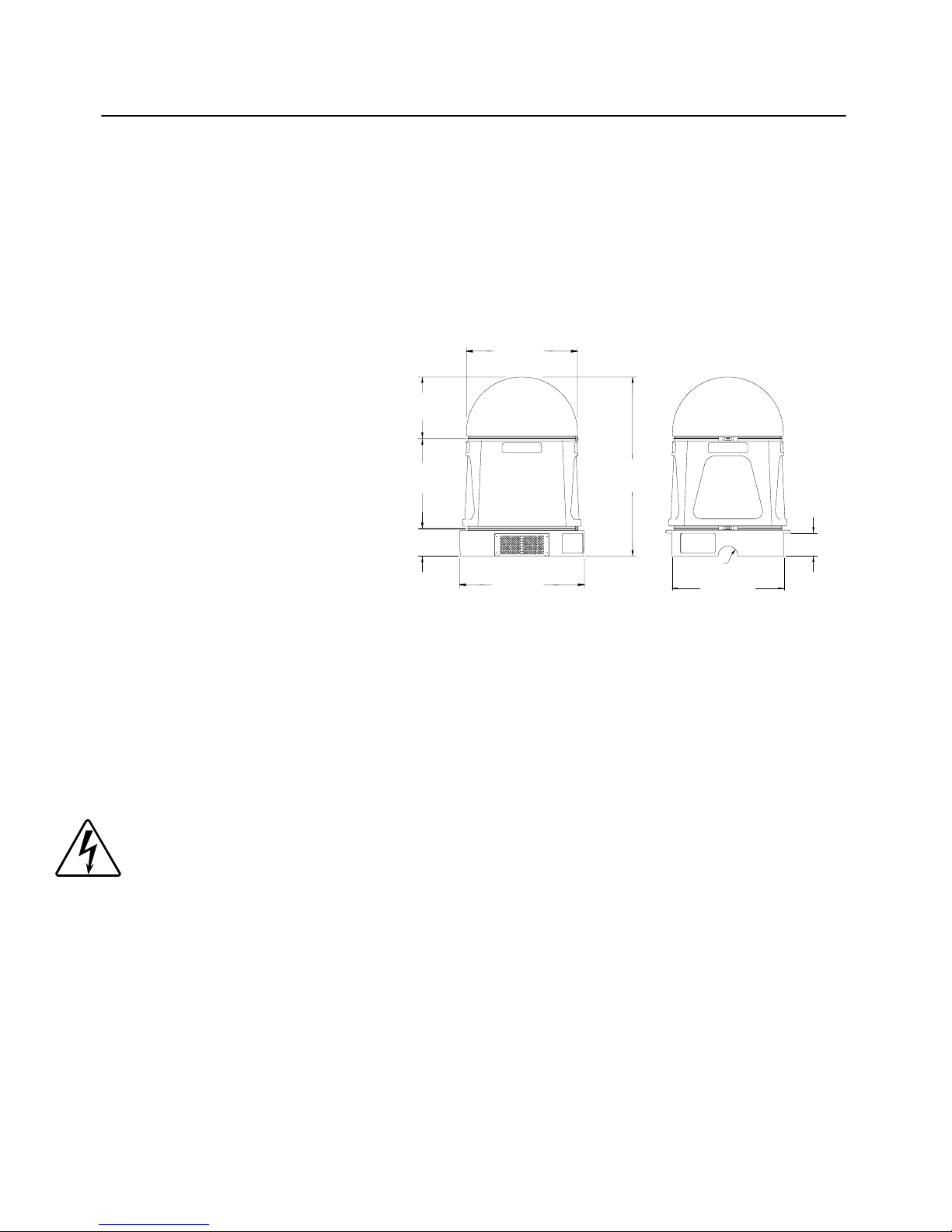
Dimensions
Height: 45 in. (115 cm)
Width: 32 in. (80 cm)
15.56 in.
(395 mm)
28.00 in.
(711 mm)
Depth: 32 in. (80 cm)
22.70 in.
(576 mm)
45.26 in.
(1150 mm)
Weight
Dome: 7 lbs (3 kg)
Housing: 15 lbs (7 kg)
Base: 45 lbs (20 kg)
Assembled (no fixture install ed ): 67 lbs (30 kg)
7.00 in.
(177 mm)
31.50 in.
(800 mm)
R 2.50 in.
(64 mm)
28.36 in.
(720 mm)
5.75 in.
(146 mm)
Electrical Specifications
Universal Ecodome 115: 115V, 50/60 Hz, 930W maximum
Universal Ecodome 208-230: 208-230V, 50/6 0 Hz , 930W maximum
Refer to the fixture’s user manual for the rated power and voltage of the fixture you plan to
install inside Ecod ome.
Warning: Class I equipment - For continued protection against electric
shock, connect this equipment to a power source that is
protected by a Ground Fault Circuit Interrupt (GFCI).
Environmental Specifications
• Ingress Protection: IP 45
• Su itable for outd oor use
intro-2 Introduction Ecodome® User Manual
Page 13
DMX Data Cabling
DMX data cables: Belden® 9841 or equivalent (meets specifications for EIA RS-485
applications) with char acte ristics listed below:
• 2 -conductor twisted pair plus a shield
• maximum capacitance between conductors - 30 pF/ft.
• maximum capacitance between conductor and shield - 55 pF/ft.
• maximum resistance of 20 Ω/1000 ft.
• nominal impedance 100–140 Ω
• 22–24 AWG with insulation having a dielectric rating of 300 volts or higher
DMX data co nnectors : 3-pin male and female XLR connectors
DMX data terminators: male XLR connector with 120 ohm terminator
Test Standards
Ecodome conforms to the following standards:
• UL 1572
• EN 60598-1
• CSA 22.2 No. 9
•EMC standards:
• EN 55022, Class A ITE
• IEC 801-2, Level 3 (6/8kV)
• IEC 801-3, Level 2 (3 V/m)
• IEC 801-4, Level 2 (1kV/.5kV)
• ENV 50204, 1996 Level 2 (3 V/m)
Safety
• Maximum ambient temperature (Ta): 40° C (104° F).
• Maximum exterior surface temperatu re: 62° C (144° F).
• Suitable for mounting on normally flammable surfaces.
• Not for residential use.
Ecodome® User Manual Introduction intro-3
Page 14

Caution and Warning Symbols
The following international symbols appear in margins throughout this manual to highlight
caution and warning messages.
Caution: This symbol appears adjacent to Caution messages. Not heeding
these messages could re sult in personal injury and/o r dama ge to
equipment.
Warning: This symbol appears adjacent to high voltag e w ar n in g mes s a ges .
Not heeding these messa ges co uld result in serious persona l
injury.
Fire Hazard: This symbol indicates that a fire hazard is present. Not
heeding these messages could result in serious personal
injury.
intro-4 Introduction Ecodome® User Manual
Page 15
Chapter 1
Chapter 1
Chapter 1Chapter 1
®
Base
Installing the Ecodome
Installing the Ecodome
Installing the EcodomeInstalling the Ecodome
Base
Base Base
Intended Audience
Ecodome must be installed by a qualified electrician only. This manual is intended for
electricians and/or building contractors already familiar with electrical wiring and
construction.
®
Unpacking Ecodome
Ecodome ships in three separate boxes—one for the dome, one for the housing, and one
for the base. Careful ly unpack each bo x and inspect the content s for damage. If a ny of the
items listed in this section are missing or damaged, you must notify both the shipping agent
and your sal e s agent immediately.
Saving the Shipping Materials
1
Do not discard the shipping box and packing materials. The box and packing materials ar e
specifically designed to protect the product during transport.
High End Systems, Inc. assumes no responsibility for products damaged during transport.
Therefore, you should return a product for repair in its original shipping carton and
packing materials.
Note: Before sending anything to the factory, be sure to call your High End
Systems, Inc. dealer/distributor for a R eturn Ma terial Authorization (RMA)
number. The factory cannot accept any goods shipped without an RMA
number.
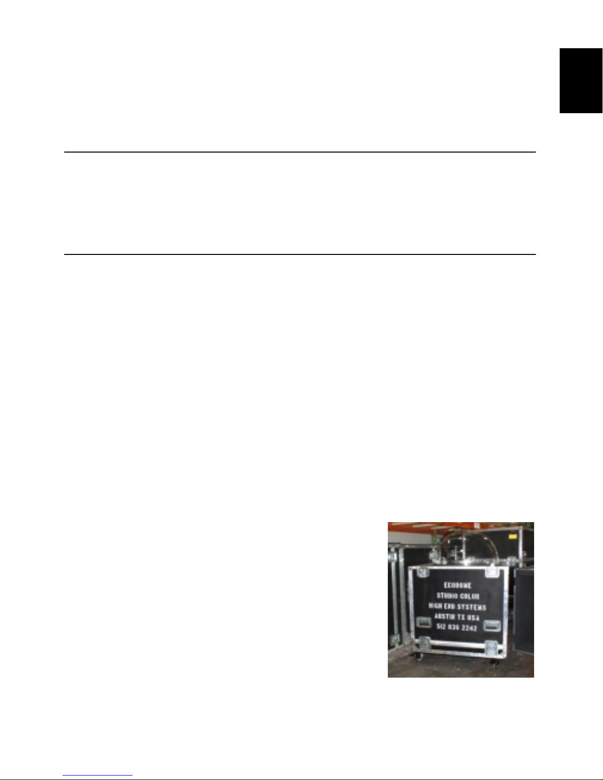
Shipping Ecodome® to Another Location
Ecodome was not designed to be shipped while a fixture
is installed inside Ecodome. If you need to ship
Ecodome to another location, High End Systems, Inc.
strongly recommends you do the following:
1. Remove the fixture installed in Ecodome and repack
the fixture in its original packaging and container.
2. Either disassemble Ecodome and repack it in its
original packaging and containers, or pack the fully
assembled Ecodome in a road case (see Figure 1-1).
Ecodome® User Manual Installing the Ecod ome® Base 1-1
Figure 1-1. Ecodome road case.
Page 16
For more information on obtaining an Ecodome road case, see “Optional Accessories”
on page intro-1.
Caution: Shipping Ecodome with a fixture installed could damage both the
fixture and Ecodome.
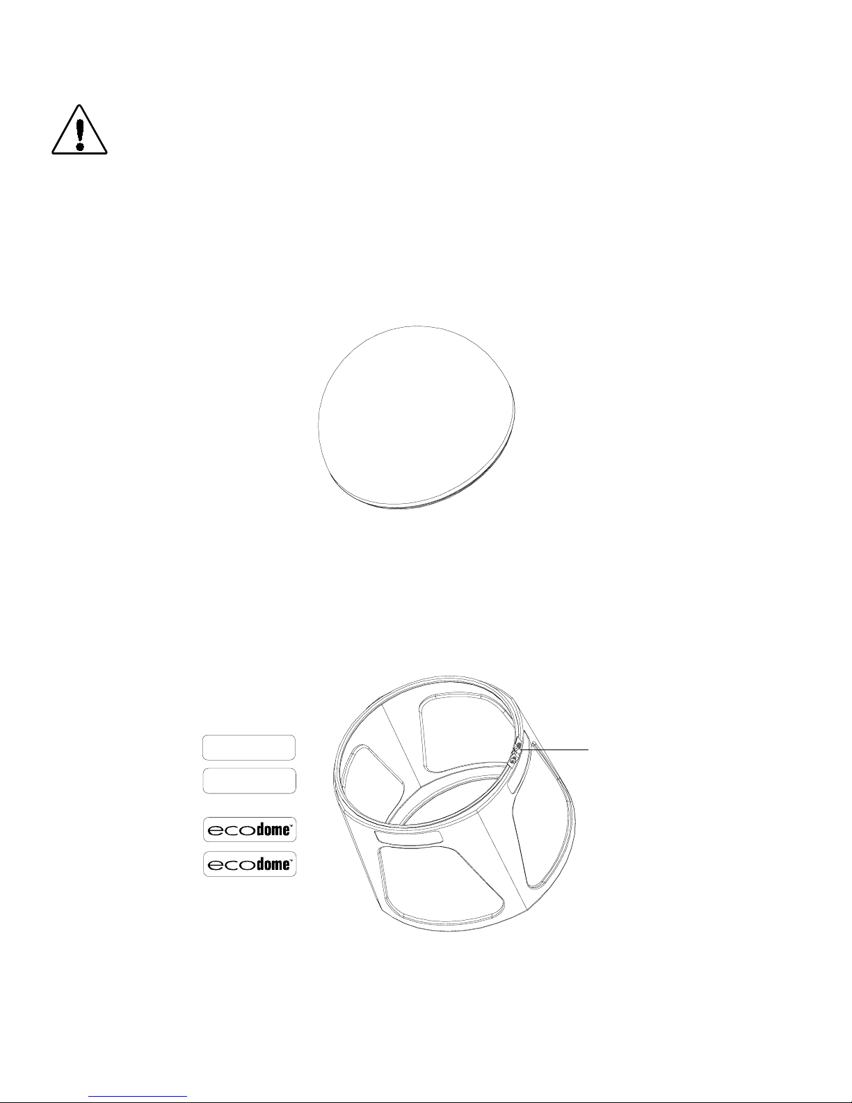
Contents of the Dome Box
The dome box contains one round dome (see Figure 1-2). Carefully remove the dome
and inspect it for cracks or scratches. If you notice cracks or scratches not caused by
shipping damage, carefully repack it in its original container and contact High End Systems
customer service (see “Contacting High End Systems” on page ii).
Figure 1-2. Ecodome dome.
Contents of the Housing Box
The housing box contains one housing with an attached clamp and four labels (see Figure
1-3).
LIGHTWA VE
LIGHTWA VE
clamp
Figure 1-3. Contents of the housing box.
1-2 Installing the Ec odome® Base Ecodome® User Manual
Page 17

Contents of the Base Box
The base box contains one base with an attached clamp, two light blocks, and various
hardware needed for installation (see Figure 1-4).
3/32" allen
wrench
clamp
light
block (2)
tamper-
resistant
screwdriver
1
1/2" regular
washers (4)
1/2" split
washers (4)
1/2" hex
nuts (4)
3/8" hex
nuts (4)
3/8" hex
screws (4)
3/8" regular
washers (4)
8-32 x 3/8" pan
head screws (4)
Figure 1-4. Contents of the base box.
Building a Foundation
Cautions: (1) Ecodome should not be mounted on a wall, upside-down, or
on a surface inclined more than 45°.
OK
0º (level)
OK
45º (maximum)
Figure 1-5. Correct mounting position.
Ecodome® User Manual Installing the Ecod ome® Base 1-3
Page 18

(2) Allow at least 24 in. (61 cm) clearance around intake and
exhaust vents.
Warning: Risk of fire and shock. This product is to be installed by a
qualified electrician only.
Installation Requirements
1. Ecodome must be installed in accordance with local and national building and
electrical codes.
2. The foundation on which Ecodome is installed must be at least 6 in. (15 cm) above
ground level.
3. Ecodome must not be installed in low-lying areas subject to flooding. Ecodome must
be mounted on a site that provides adequate drainage so that Ecodome is never
immersed in standing water.
4. Ecodome model “Universal Ecodome” is to be used only with High End Systems
fixture models “Studio Color 575-M,” “Studio Color 575-S,” “Studio Color,” “Studio
Spot,” “Studio Color 250,” or “Studio Spot 250.”
Foundation Layout
You will need:
• suitable foundation materials (concrete, steel, wood, etc.) to build a 32 in. (81 cm)
minimum diameter foundation
• four 1/2" Unified National Coarse (UNC) studs for mounting Ecodome
Use the following guidelines to build the Ecodome foundation:
1. Construct a foundation of suitable material (concrete, steel, wood, etc.) that allows at
least 32 in. (81 cm) minimum diameter. Make sure the top of the foundation is at least
6 in. (15 cm) above ground level.
1-4 Installing the Ec odome® Base Ecodome® User Manual
Page 19

2. Install four 1/2" mounting studs into the foundation in a square pattern with the center
of the studs measuring 17 inches apart (see Figure 1-6).
17.00"
32.00"
32.00"
1
8.50"
32.00"
17.00"
8.50"
4 mounting
studs
6.00" min.
Figure 1-6. Recommended foundation layout for Ecodome.
Ecodome® User Manual Installing the Ecod ome® Base 1-5
Page 20

Assembling and Mounting the Base
This section shows how to mount the Ecodome base on the foundation you have already
prepared.
You will need:
• ratchet and
• 3/4" deep socket
•6" extension
•scissors
• four 1/2" regular washers (supplied with Ecodome)
• four 1/2" split washers (supplied with Ecodome)
• four 1/2" mounting nuts (supplied with Ecodome)
Use scissors to cut the cable tie wrap on the cables under the Ecodome base.
1
power and DMX
data cables
1-6 Installing the Ec odome® Base Ecodome® User Manual
Page 21

2
Data Out
Extend the power and DMX data cables through either of the recessed areas
on the Ecodome base.
1
Data In
3
power
recessed areas on base
Place the four Ecodome mounting holes over the four studs in your
foundation.
Ecodome® User Manual Installing the Ecod ome® Base 1-7
Mounting hol e s ( 4)
Page 22

4
Place a 1/2" regular washer, a 1/2" split washer, and a 1/2" hex nut over each
of the four foundation studs inside the Ecodome base.
5
Use a ratchet to tighten all four 1/2" hex nuts securely.
1-8 Installing the Ec odome® Base Ecodome® User Manual
Page 23

Chapter 2
Chapter 2
Chapter 2Chapter 2
Installing the Fixture
Installing the Fixture
Installing the FixtureInstalling the Fixture
You should have already prepared the site and mounted the Ecodome base as described
in Chapter 1 before following the instructio ns in this chapter.
You will need:
• a fixture suitable for mounting in Ecodome (see “Installation Requirements” on
page 1-4)
• ratchet and
• 3/4" deep socket
• #2 Philips-head (torque-measuring) screwdriver
• 3 /32" allen wrench (supplied with Ecodome)
• two light blocks (supplied with Ecodome)
• four 8-32 x 3/8" pan head screws (supplied with Ecodome)
• four 3/8" hex screws (supplied with Ecodome)
• four 3/8" regular washers (supplied with Ecodome)
• four 3/8" hex nuts (supplied with Ecodome)
2
1
Locate the support beams on the Ecodome base.
support beams
Ecodome® User Manual Installing the Fixture 2-1
Page 24

2
hole 1
hole 2
hole 3
Determine whether the support beams are correctly assembled for the fixture
you wish to install. If you wish to install a Studio Spot 575 fixture, position the
support beams in holes 2 and 3. If you wish to install a Studio Color S, Studio
Color M, Studio Color 575, Studio Spot 250, or Studio Color 250 fixture,
position the support beams in holes 1 and 2.
Studio Spot 575
fixtures
Use two people to place the fixture on the Ecodome support beams. If you are
installing a Studio Color S, Studio Color 575, or Studio Spot 575 fixture, you
3
must orient the fixture so that the fixture’s heatsink faces the Ecodome blower .
blower
Studio Color S, Studio Color M,
Studio Color 575, Studio Color 250,
and Studio Spot 250 fixtures
heatsink on Studio Color S,
Studio Color 575, and
Studio Spot 575 fixtur es
2-2 Installing the Fixture Ecodome® User Manual
Page 25

4
Secure the fixture to the Ecodome base by installing a 3/8" hex screw, 3/8" flat
washer, and a 3/8" hex nut through the top of the Ecodome support beam
and each of the four mounting holes on the fixture’s bottom plate.
2
Ecodome® User Manual Installing the Fixture 2-3
Page 26

5
If you are installing a Studio Spot 575 or Studio Spot 250 fix ture, you must
attach a light block to each side of the fixture. The light blocks will prevent
damage to the inside of the Ecodome housing.
Caution: Failure to install light blocks will result in damage to
the Ecodome Housing.
Using a 3/32" allen wrench (for Studio Spot 575 fixtures) or a #2 Phillips-head
screwdriver (for Studio Spot 250 fixt ures), remove the two outer screws on
the bottom of the fixture’s yoke. Insert an 8-32 pan head scr ew i n each outer
screw hole on the bottom of the fixture’s yoke. Do not fully tighten the screws.
Install the light block by placing the large ends of its keyhole slots over the
two 8-32 pan head screws on the fixture’s yoke. Lightly press down on the
light block until the screws are in the small end of the keyhole slots. Tighten
the screws se curely.
Replace the outer screws on the bottom of the fixture's yoke
Studio Spot 575
Studio Spot 250
Install the light block
2-4 Installing the Fixture Ecodome® User Manual
Page 27

Connecting the Cabling
You will need:
•#2 Phillips-head screwdriver
• flat head screwdriver with a 3/16" blade
Locate the Ecodome circuit box on the Ecodome base.
1
circuit box
2
2
Using a #2 Phillips-head screwdri ver, loosen (but do not remove) the two
screws from the circuit bo x l id . Slide the circuit box lid to the side so that the
screws are positioned in the lar ge end of the k eyhole slot. Pull the circuit box
lid out and over the screws to remove the lid.
slide
the lid
keyhole
slots
loosen the
two screws
Ecodome® User Manual Installing the Fixture 2-5
Page 28

3
Using a flat head scr ewdriver, loosen the two cable clamp screws. Insert the
fixture’s power cord thr ough the cable clamp into the cir cuit box.
Ecodome
power cord
cable clamp screws
power in
fixture
power cord
2-6 Installing the Fixture Ecodome® User Manual
Page 29

4
Using a flat head screwdriver, loosen the three Ecodome terminal screws
reserved for the fixture’s cable (shaded below).
Insert the fixture’s Live, Neutral, and Ground/Earth wires into the
appropriatly-marked terminal. The Ecodome terminals are marked “L” for
Live, “N” for Neutral and “ ” for Ground/Earth.
For more information on the fixture’s power cord, consult the fixture’s user
manual.
Live
Neutral
terminal screws
Ground
2
After inserting each wire, tighten its terminal screw to 12 in. lb. (1.36 N-m)
to secure the wire to the terminal block.
When you have finished, tighten the cable clamp screws and replace the
circuit box lid.
Ecodome® User Manual Installing the Fixture 2-7
Page 30

5
Use a junction box to connect the Ecodome power cord to the mains power
supply.
Ecodome power cord
mains
junction
box
power
supply
The mains power supply must include branch circuit protection sized in accordance with
your local and national electrical codes. High End Systems, Inc. recommends that you
also use a Ground Fault Circuit Interrupt (GFCI) for all outdoor installations.
The cores in the Ecodome mains lead are colored in accordance with the following code:
• green and yellow: earth
• blue: neutral
• brown: live
THIS EQUIPMENT MUST BE EARTHED.
2-8 Installing the Fixture Ecodome® User Manual
Page 31

6
Locate the fixture’s DMX data connectors.
2
data connectors
Ecodome® User Manual Installing the Fixture 2-9
Page 32

7
Connect Ecodome’s male data cable to the fixture’s Data Out
connector and Ecodome’s female data cable to the fixture’s Data In
connector.
Use a junction box to connect the other end of Ecodome’s data cables
to either the controller or the next Ecodome on the DMX link.
Ecodome's DMX cables
junction
box
2-10 Installing the Fixture Ecodome® User Manual
Page 33

Final Component Assembly
This section describes how to assemble the final components before putting Ecodome into
use.
You will need:
• four housing labels (supplied with Ecodome)
• tamper-resistant screwdriver tool (supplied with Ecodome)
Remove the paper backing from the housing labels and carefully apply one
label to each recessed area at the top of the housing. Use firm, even pressure
1
to prevent bubbles from forming under the label.
2
Ecodome® User Manual Installing the Fixture 2-11
Page 34

2
Place the Ecodome housing (with attached clamp) over the Ecodome base
(with attached clamp). Place the dome over the housing.
clamps
2-12 Installing the Fixture Ecodome® User Manual
Page 35

Secure the clamps by tightening the clamp bolts with the tamper-resistant
screwdriver tool. Tighten the bolts until you cannot rotate either the dome or
3
the housing.
Note: If you mounted Ecodome on an incline, orient the clamp
bolts and the base vents 90° away from the direction of the
incline to provide added protection against moisture
accumulating inside Ecodome.
Moisture
water flow
2
vents (located on
both sides of Ecodome)
Clamp bolt s
45º (maximum)
Ecodome® User Manual Installing the Fixture 2-13
Page 36

2-14 Installing the Fixture Ecodome® User Manual
Page 37

Chapter 3
Chapter 3
Chapter 3Chapter 3
Performing Maintenance
Performing Maintenance
Performing MaintenancePerforming Maintenance
You must observe the following warnings and cautions when performing any type of
service on either Ecodome or the fixture installed inside Ecodome:
Warnings: (1) Disconnect power before servicing.
(2) Consult the documentation provided with the fixture
installed inside Ecodome for important safety information.
(3) Do not operate this equipment without complete lamp
enclosure in place or if sh i eld s , lenses, or ultraviolet screens
are damaged.
(4) Change shields, lenses, or ultraviolet screens if they have
become visibly damaged to such an extent that their
effectiveness is im pa i red , for example by cracks or deep
scratches.
(5) Never look di rectly at the lamp whi l e the lamp is on.
3
Caution: This fixture must be serviced by qualified personnel. The
information listed in this section is intended to assist qualified
service personnel only.
Servicing the Fixture
Consult the fixture’s documentation for recommended fixture cleaning and maintenance
procedures.
®
Servicing Ecodome
Some basic recommended service procedures for Ecodome are listed below.
Cleaning Ecodome
To clean the housing, use a cloth and non-abrasive household soap and/or cleaner to wipe
away built-up dirt from the housing.
To clean the dome, leave the dome on the Ecodome unit and follow the steps below:
®
1. If mud or other debris has accumulated on the dome, first spray the dome off with
water.
Ecodome® User Manual Performing Maintenance 3-1
Page 38

2. After cleaning away built-up debris, use a soft cloth (a wet cotton rag, chamois, or
cheese cloth is recommended) and water or mild glass cleaner to wipe away dirt
and debris from the o ut e r do me surface.
Caution: Do not use paper towels or other abrasive materials to clean the
dome; doing so can leave scratches which may impair image
quality.
3. Optional. As a final cleaning, dampen a soft cloth with denatured rubbing alcohol
to thoroughly clean the dome’s surface.
Checking Intake/Exhaust
You must leave at least 24 inches (61 cm) clearance around both the intake and exhaust
vents, located on opposite sides of the Ecodome base. Because wind and weather
conditions can cause debris to build up around the vents, you should regularly inspect for
any of the following:
• Grass clippings or leaves: Use your hands or a vacuum to clear away leaves
and clippings.
• Water , snow, or soil: Accumulations of water or soil within 24 inches (61 cm) of
Ecodome’s intake or exhaust could prevent the fixture from operating properly, or
pose a major hazard to the fixture.
If any of the above regularly accumulate around Ecodome, contact High End Systems
customer service (see “Contacting High End Systems” on page ii).
Replacing Air Filters
Caution: Electrically isolate Ecodome before following these instructions.
Check Ecodome’s intake and exhaust air filters
whenever you service the fixture installed in
Ecodome (for example, when you change
lamps). Ecodome’s air filters must be replaced
when they ar e visibly clogged with dirt.
To replace the air filter:
1. Use the tamper-proof screwdriver
(shipped with Ecodome) to remove the
base clamp.
2. Carefully lift the housing and dome
from the base (and fixture).
3. Locate the air filters (see Figure 3-1).
4. Loosen the three air filter cover
thumbscrews surrounding the air filter
and remove the air filter cover.
exhaust air filter
(under blower assembly)
intake
air filter
Figure 3-1. Location of the air filt ers.
3-2 Performing Maintenance Ecodome® User Manual
Page 39

Note: The entir e blow er as se mbly serves as the exhaust air filter cover. To access
the exhaust air filter, loos e the three thumbscrews around the base of the
blower assembly and lift the entire blower assembly off the base.
5. Replace the air filter.
You must use a Fram
from your High End Systems dealer/distributor (see “Optional Accessories” on
page intro-1).
6. Replace the air filter cover and tighten the air filter cover thumbscrews.
7. Replace the housing and dome over the base. Use the tamper-proof screwdriver
to tighten the base clamp.
®
CA 5056 air filter. You can purchase CA 5056 air filters
Oiling the Blower Motor
You should oil the blower motor every six months.
Caution: Electrically isolate Ecodome before following these instructions.
To oil the blower motor:
1. Use the tamper-proof screwdriver (shipped with Ecodome) to remove the base
clamp.
3
2. Carefully lift the housing and dome from the base (and fixture).
3. Locate the blower motor (see
Figur e 3-2).
4. Oil the blower motor in the
holes on each side of the motor
(see Figure 3-2).
You must use 10 to 20 drops of
either SAE 10W or 20W nondetergent oil (ML-type) or
electric motor oil.
5. Replace the housing and dome
over the base. Use the tamperproof screwdriver to tighten the
base clamp.
blower motor
holes
Figure 3-2. Oiling the blower motor.
Ecodome® User Manual Performing Maintenance 3-3
Page 40

3-4 Performing Maintenance Ecodome® User Manual
Page 41

Appendix A
Appendix A
Appendix AAppendix A
Important Safety Information
Important Safety Information
Important Safety InformationImportant Safety Information
Conditions of Acceptability for ETL/C-ETL Recognition of Ecodome
Ecodome is an ETL/C-ETL Recognized Component that is acceptable for use only under
the following conditions:
1. Ecodome must be installed in accordance with local and national building and
electrical codes.
2. A suitable mounting site with drainage is provided that does not subject the enclosur e
to submersio n in liquid.
3. The model Universal Ecodome is to be used only with HID Lighting Fixture, Model
“Studio Color 575-M,” “Studio Color 575-S,” “Studio Color,” “Studio Spot,” “Studio
Color 250,” or “Studio Spot 250.”
WA RNING - For Continued Protection Against Electric Shock
1. Risk of fire and electric shock. This product is to be installed by a qualified electrician
only.
2. Class I equipment - For continued protection against electric shock connect this
equipment to a ground fault protected power source only.
3. Disconnect power before servicing.
4. Do not install an accessory in Ecodome unless you first contact High End Systems
customer service.
5. IMPORTANT – The cores in the mains lead are colored in accordance with the
following code:
• green and yellow: earth
• blue: neutral
• brown: live
A
6. THIS EQUIPMENT MUST BE EARTHED.
WARNING - For Continued Safe Operation
1. Consult the documentation provided with the luminaire you are using for installation
instructions and important safety information.
2. Shipping Ecodome to another location with a fixture installed could result in damage
to both the fixture and to Ecodome.
3. Not for residential use.
4. Change the lamp if it becomes damaged or thermally deformed.
Warning: For Continued Protection Against Exposure To Excessive Ultraviolet
(UV) Radiat i on
1. Do not operate this equipment without complete lamp enclosure in place or if shields,
lenses, or ultraviolet screens are damaged.
Ecodome® User Manual Important Safety Informati on A-1
Page 42

2. Change shields, lenses, or ultraviolet screens if they have become visibly damaged to
such an extent that their effectiveness is impaired, for example by cracks or deep
scratches.
3. Never look directly at the lamp while the lamp is on.
Installation Instructions
1. Allow at least 24 inches (61 cm) clearance around intake and exhaust. Do not
operate in low-lying areas subject to flooding or in areas subject to standing water.
2. Ecodome cannot be mounted on a wall or upside-down.
Maintenance Instructions
1. Disconnect power before servicing.
2. Check both intake and exhaust air filters whenever you service the fixture (for
example, when you change lamps). Air filters must be replaced when they are visibly
clogged wit h di rt.
3. You must use a Fram
air filters from your Hi gh End Systems, Inc. dealer distributor ( part number 99170003).
®
CA 5056 air filter or the equivalent. You can purchase CA 5056
Appendice A
Important: Informations De Sécurité
Conditions d’acceptation pour la reconnaissance d’Ecodome par l’ETL/C-ETL
Ecodome est un composant reconnu par l’ETL/C-ETL lorsque les conditions suivantes sont
satisfaites :
1. Ecodome doit être installé conformément aux codes de réglementation locaux et
nationaux concernant le bâtiment et les installations électriques.
2. Le support de base sur lequel est installé Ecodome doit être à une distance minimum
de 15 cm (6 pouces) au-dessus du niveau du sol ; de plus, Ecodome ne doit pas être
utilisé dans des zones basses susceptibles d’être inondées ou dans des zones pouvant
être submergées sous des eaux stagnantes.
3. Le modèle “Ecodome Universal” doit être utilisé uniquement avec le modèle de
projecteur “Studio Color 575-M,” “Studio Color 575- S,” “Studio Color,” “Studio Spot,”
“Studio Color 250,” ou “Studio Spot 250.”
AVERTISSEMENT – Pour une protection continue contre l’électrocution
1. Risque d’incendie et d’électrocution. Ce produit doit être installé uniquement par un
électricien qualifié.
2. Equipement de Classe I – pour une protection continue contre l’électrocution,
branchez cet équipement à une source d’alimentation protégée par un interrupteur
de mise à la terre.
3. Débranchez l’appareil avant toute intervention de maintenance.
A-2 Important Safety Information Ecodome® User Manual
Page 43

4. N’installez pas d’accessoire dans Ecodome sans contacter d’abord le Service
consommateurs de High End Systems.
AVERTISSEM ENT – Pour une sécurité d’opération continue
1. Pour lire les instructions d’installation et d’importantes informations de sécu rité,
consultez la documentation livrée avec l’appareil d’éclairage que vous utilisez.
2. Le transport d’Ecodome alors qu’un projecteur est monté sur celui-ci risque
d’endommager à la fois le projecteur et le composant Ecodome.
3. Cet appareil n'est pas destiné à un usage domestique.
4. Changer la lampe si elle est endommagée ou thermiquement déformé.
Mise en garde: pour un e pro tection permanente co nt re des expositions
excessives aux rayons ultra violets (UV)
1. Ne pas utiliser cet appareil si le boîtier de la lampe n'est pas complètement fixé ou si
les blindages, lentilles, ou écrans ultraviolets sont endommagés.
2. Changer les blindages ou l es écrans ultraviolets s'ils so nt visiblement endommagés au
point que leur efficacité aient été altérée, par exemple par des fissures ou de
profondes égratignures.
3. Ne jamais regarder directement la lampe quand celle ci est allumée.
Instructions pour l’installation
1. Laissez un dégagement minimum de 61 cm (24 pouces) autour de l’entrée d’air et de
l’échappement. N’utilisez pas l’appareil dans des zones basses susceptibles d’être
inondées, ou dans des zones pouvant être submergées sous des eaux profondes et
stagnantes.
2. L'Ecodome ne peut pas être monté sur un mur ou en tête-à-queue.
A
Instructions pour la maintenance
1. Débranchez l’appareil avant toute intervention de maintenance.
2. Vérifiez le filtre de l’entrée d’air et celui de l’échappement chaque fois que vous
effectuez une opération de maintenance sur l’appareil (par exemple, lorsque vous
changez une lampe). Les filtres à air doivent être remplacés lorsqu’ils sont visiblement
encrassés.
3. Vous devez utiliser un filtre à air FRAM â CA 5056 ou équivalent. Les filtres à air FRAM
â CA 5056 sont en vente chez les distributeurs agréés High End Systems, Inc. (numéro
de pièce 99170003).
Ecodome® User Manual Important Safety Informati on A-3
Page 44

Anhang A
Wichtige Sicherheitshinweise
Anforderung der ETL/C-ETL-Norm für Ecodome
Ecodome entspricht der Norm einer von ETL/C-ETL akzeptierten Komponente, wenn die
folgenden Anforderungen erfüllt sind:
1. Ecodome muß gemäß der örtlichen und nationalen elektrischen Richtlinien und
Bauvorschriften installiert werden.
2. Das Fundament auf welches Ecodome installiert wird, muß sich mindestens 15 cm (6
Zoll) über der Grundgleiche befinden. Außerdem ist Ecodome nicht in tiefgelegenen
Gebieten, die Überschwemmungen ausgesetzt sind oder in Gebieten mit stehendem
Wass er zu betreiben.
3. Das Ecodome Modell “Universal” ist nur mit dem Leuchtenmodell “Studio Color 575M,” “Studio Color 575-S,” “Studio Color,” “Studio Spot,” “Studio Color 250,” oder
“Studio Spot 250” zu verwenden.
WARNUNG – Zum Schutz vor elektrischen Schlägen
1. Feuergefahr und Gefahr eines elektrischen Schlages. Dieses Produkt sollte nur von
einem qualifizierten Elektriker installiert werden.
2. Gerät der Klasse I – Zum Schutz vor elektrischen Schlägen ist dieses Gerät an eine mit
Erdschluß geerdete Stromversorgung anzuschließen.
3. Vor dem Ausführen von Servicearbeiten ist das Gerät von der Stromversorgung zu
trennen.
4. Bevor Zubehörgeräte in Ecodome installiert werden, müssen Sie sich mit der
Kundendienstabteilung von High End System s in Verbindung setzen.
WARNUNG – Zur sicheren Betriebsweise
1. Lesen Sie die Installationsanleitungen und wichtigen Sicherheitshinweise in der
Dokumentation zur Leuchte.
2. Der Versand von Ecodome mit einer installierten Leuchte könnte sowohl die Leuchte
als auch Ecodome beschädigen.
3. Nicht für den Hausgebrauch bestimmt.
4. F alls die Lampe beschädigt oder durch Wärmeeinwirkung verformt ist, muß sie
ausgewechselt werden.
WARNUNG: ZUM SCHUTZ GEGEN ÜBERMÄSSIGE ULTRAVIOLETT (UV)BESTRAHLUNG
1. Benutzen Sie dieses Gerät nur, wenn das komplette Lampengehäuse fest eingebaut ist;
ebenfalls dürfen keine der Schutzabdeckungen, Linsen oder der UV-Schutz
Beschädigungen aufweisen.
A-4 Important Safety Information Ecodome® User Manual
Page 45

2. Die Schutzabdeckungen, Linsen und der UV-Schutz müssen ausgewechselt werden,
wenn sie sichtlich dermaßen beschädigt sind, daß sie ihre Wirksamkeit einbüßen, z.B.
infolge von Rissen oder tiefen Kratzern.
3. Nie direkt in die eingeschaltete Lampe schauen.
Installationsanleitungen
1. Um die Lufteinlaß- sowie um die Luftaustrittsöffnung ist ein Sicherheitsabstand von 61
cm (24 Zoll) erforderlich. Das Gerät nicht in tiefgelegenen Gebieten, die häufig
Überschwemmungen ausgesetzt sind oder in Gebieten mit tief stehendem Wasser
betreiben.
2. Der Ecodome darf nicht an der Wand oder kopfstehend befestigt werden.
Wartungsanleitungen
1. Vor dem Ausführen von Servicearbeiten ist das Gerät von der Stromversorgung zu
trennen.
2. Bei der Wartung der Leuchten ist sowohl der Lufteinlaß- als auch der Luftaustrittsfilter
zu prüfen (z.B. beim Wechseln der Lampen). Die Luftfilter sind zu ersetzen, wenn sie
sichtbar verschmutzt sind.
3. Als Filter ist ein Fram CA5056 oder ein entsprechender Luftfilter zu verwenden. CA
5056 Luftfilter können bei Ihrem Vertragshändler von High End Systems, Inc.
erworben werden (Teile-Nr.: 99170003).
A
Appendice A
Informazioni Importanti Di Sicurezza
Condizioni per l’omologazione ETL/C-ETL di Ecodome
Ecodome è un componente omologato ETL/C-ETL qualora siano rispettate le seguenti
condizioni:
1. Ecodome deve essere installato conformemente alle normative edili ed elettriche
locali e nazionali.
2. Il luogo di installazione di Ecodome deve essere rialzato dal suolo di almeno 15 cm.
Ecodome non deve inoltre essere messo in funzione in aree ribassate dove sussiste il
pericolo di inondazione o in zone con presenza di acque morte profonde.
3. Il modello “Universal” deve essere usato unicamente con appar e cchiature “Studio
Color 575-M,” “Studio Color 575-S,” “Studio Color,” “Studio Spot,” “Studio Color
250,” o “Studio Spot 250.”
AVVERTENZA - Per una protezione continua contro il rischio di scosse
elettriche
1. Pericolo di incendio e scosse elettriche. Questo prodotto deve essere installato
solamente da un elettricista qualificato.
Ecodome® User Manual Important Safety Informati on A-5
Page 46

2. Apparecchiatura di classe I - per garantire una continua protezione contro le scosse
elettriche, collegare questo dispositivo a una fonte di alimentazione elettrica con
messa a terra ad e g u a t a.
3. Scollegare dalla corrente prima di effettuare la manutenzione.
AVVERTENZA - Per garantire un funzionamento sicuro e duraturo
1. F are riferimento alla documentazione acclusa al dispositivo in dotazione per le
istruzioni di installazione e le informazioni sulla sicurezza.
2. La spedizione di Ecodome con un'apparecchiatura installata potrebbe provocare
danni sia all'apparecchiatura sia a Ecod o m e.
3. Questa apparechiatura non e' per uso domestico.
4. Cambiare la lampada in caso si danneggi o deformi per le alte temperature.
AVVERTENZA: PER PROTEGGERSI CONTRO LE RADIAZIONI DEI RAGGI
ULTRAVIOLETTI:
Non usare questa apparecchiatura se il dispositivo di chiusura della almpada non é
completamente fissato o se gli schermi protettivi, le lenti, o gli schermi ultravioletti si sono
visibilmente danneggiati di maniera tale che la loro efficac i a sia stata ridotta --- ad
esempio, se vi sono visibili spaccature o graffi profondi. Mai guardare direttamente verso
la lampadina quando sia accesa.
Istruzioni per l'installazione
1. Lasciare uno spazio libero di almeno 61 cm attorno ai condotti di ingresso e di scarico.
Non operare l'unità in aree ribassate dove sussiste il pericolo di inondazione o in zone
con presenza di acque morte profonde.
2. Ecodome non può essere montato su una parete o sottosopra.
Istruzioni per la manutenzione
1. Scollegare dalla dalla corrente prima di effettuare la manutenzione.
2. Controllare i filtri dell'aria dei condotti di ingresso e di scarico a ogni intervento di
manutenzione (ad esempio, quando si cambiano le lampadine). Questi filtri devono
essere cambiati quando appaiono otturati da depositi e sporco.
3. Utilizzare un filtro dell'aria Fram
®
CA 5056 o equivalente. I filtri CA 5056 sono
disponibili presso distributori e rivenditori High End Systems, Inc. (numero di
ordinazione 99170003).
A-6 Important Safety Information Ecodome® User Manual
Page 47

Apendice A
Informacion Importante De Seguridad
Condiciones de aceptabili dad para el reconocimiento ETL/C-ETL de Ecodome
Ecodome es un componente reconocido por ETL/C-ETL cuando se cumplen las
condiciones de aceptabilidad siguientes:
1. Ecodome debe instalarse de acuerdo con los códigos locales y nacionales de
construcción y electricidad.
2. El cimiento sobre el cual se instale Ecodome debe estar por lo menos a 15 cm (6
pulgadas) sobre el nivel del suelo; además, no debe operarse el Ecodome en áreas
bajas susceptibles de ser inundadas o en áreas que puedan sufrir aguas estancadas.
3. El modelo Ecodome llamado “Universal” debe utilizarse únicamente con el accesorio
“Studio Color 575-M,” “Studio Color 575-S,” “Studio Color,” “Studio Spot,” “Studio
Color 250,” o “Studio Spot 250” modelo.
ADVERTENCIA: Para una protección cons tante contra las descargas eléctricas
1. Peligro de incendio y descarga eléctrica. Unicamente un electricista calificado debe
instalar este producto .
2. Equipo Clase I. Para una protección constante contra las descargas eléctricas, conecte
este equipo únicamente a una fuente de alimentación protegida contra fallas de tierra.
3. Desconecte la alimentación antes de dar servicio.
4. No instale un accesorio en el Ecodome sin antes ponerse en contacto con Servicio a
clientes de High End Syst ems .
A
ADVERTENCIA: Para una operación segura
1. Consulte la documentación proporcionada con la luminaria que utiliza para obtener
las instrucciones de inst a la c ión e información important e de seguridad.
2. El envío de Ecodome con un accesorio instalado puede dañar tanto al accesorio
como al Ecodome.
3. Prohibido su uso en ambientes residenciales.
4. Cambie la lámpara si ésta se avería o deforma por acción térmica.
ADVERTENCIA: PARA PROTECCIÓN CONTINUA CONTRA LA EXPOSICIÓN A
R A DIACIÓN ULTR AVIOLETA (UV) EXCESIVA
1. No opere este equipo sin tener colocada en su lugar la caja protectora completa de la
lámpara o bien, si el blindaje , los lentes o las pantallas ultravioletas están dañadas.
2. Cambie el blindaje, los lente s o las pa nt allas u ltra viole ta si n ota una avería visibl e, a ta l
grado que su eficacia se vea comprometida. Por ejemplo, en el caso de grietas o
rayaduras profundas.
3. Jamás mire directamente a la lámpara en tanto ésta esté encendida.
Ecodome® User Manual Important Safety Informati on A-7
Page 48

Instrucciones de instalación
1. Deje por lo menos 61 cm (24 pulgadas) de espacio alrededor de la entrada y el
escape. No opere en áreas bajas susceptibles a inundaciones o en áreas donde pueda
sufrir aguas profundas y estancadas.
2. El Ecodome no puede montarse en una pared ni boca abajo.
Instrucciones de mantenimiento
1. Desconecte la alimentación eléctrica antes de dar servicio.
2. Revise los filtros de aire de entrada y de escape siempre que dé servicio al accesorio
(por ejemplo, cuando cambie lámparas). Los filtros de aire deben reemplazarse
cuando presenten obstrucciones de suciedad.
3. Debe utilizar un filtro de aire Fram
aire CA 5056 mediante su distribuidor de High End Systems, Inc. (número de pieza
99170003).
®
CA 5056 o equivalente. Puede adquirir filtros de
Vigtig Sikkerhedsin formation - DANMARK
Advarsel: Beskyttelse mod elektrisk chock.
Vigtigt!
Lederen med gul/groen isolation maa kun tilsluttes en klemme maerket
eller
A-8 Important Safety Information Ecodome® User Manual
Page 49

Introduction
The Dome .....................................................................................................................intro-1
Optional Acces sori e s . .............. ............... ............... ............... ............... .............. ...........intro-1
Specifications ..................................... .................................................. ......................... intro-2
Model Numbe rs ............ .............. ............... ........................... ............... ..................intro-2
Dimensions . ............... ............... ............... .............. ............... ............... ............... ...intro-2
Weight .... .................. ................. ................. ............... ................. ................. ...........intro-2
Electrical Spec i fi c a ti ons ................. ............... .............. ............... ............... .............intro-2
Environmental Specificatio ns ............. .. ............... ............... ............... .............. ......intro-2
DMX Data Cablin g ........ .. ............... ............... .............. ............................ .............. .intro-3
Test Standards ........................................................................................................intro-3
Safety ...... ............... ................. .................. .............. .................. ............... ...............intro-3
Caution and Warning Symbols ....................................................................................intro-4
Chapter 1 Installing the Ecodome® Base
Intended Audienc e .................................... ........................... ............... .............. ............... ..1-1
Unpacking Ecodome
Saving the Shipping Materials .....................................................................................1-1
Shipping Ecodome
Contents of the Dome Bo x ............... ... ............... .............. ............... ............... ..............1-2
Contents of the Housin g Box ........... ... ............... .. ............... ............... .............. ............1-2
Contents of the Base Box .................... ............... .............. ............... ............... .. ............1 -3
Building a Foundation ........................................................................................................1-3
Installation Requirements ............................................................................................1-4
Foundation Layout ........... ............... ... ............... .. ............... .. ............... ... .............. ... ....1-4
Assembling and Mounting the Base ............... .. ... .............. ... .. ............... ... .. ............... .. ... ....1-6
®
........... ..... .. ..... ..... ... ..... ..... .. ..... ..... .. ..... ..... ... ..... ..... .. ..... ..... .. ..... ..... ..1 -1
®
to Another Location ...........................................................1-1
Chapter 2 Installing the Fixture
Connecting the Ca b li n g ..................... ... ............... ........................... ............... .....................2-5
Final Component Assembly .............................................................................................2-11
Chapter 3 Performin g Maintenance
Servicing the Fixt ure ... ............... ............... ............... .............. ............... ............... ..............3-1
Servicing Ecodome
Cleaning Ecodome
Checking Intake/Exhaust ... ... ............... ............... .............. ............... ............... ..............3-2
Replacing A ir Fi lters .................. ........................... ............... ........................... ..............3 -2
Oiling the Blower Motor ..............................................................................................3-3
®
.......................................................................................................... 3-1
®
.................................................................................................... 3-1
Appendix A Important Safety Information
Appendice A Important: Informations De Sécurité ............ ... ............... .............. ...........A-2
Anhang A Wichtige Sicherheitshinweise ........................................................................A-4
Appendice A Informaz i oni Impo rtanti Di Sicurez za ....... ............... ... .............. ............... . A-5
Apendice A Informac i on Im p ort a n t e De Seg u ri da d ........... ... ............... .............. ...........A-7
Studio Spot 250 / Studio Col or 250 User Manual 1-9
Page 50

Vigtig Sikkerhed si nformation - DANMARK .......... ... .. ............... ............... .. ............... ........A-8
1-10 Studio Spot 250 / Studio C olor 250 User Manual
Page 51

Figure 1-1. Ecodome road case. .......................................................................................1-1
Figure 1-2. Ecodome dome. ..............................................................................................1-2
Figure 1-3. Contents of the housing box. ...........................................................................1-2
Figure 1-4. Contents of the base box. ................................................................................1-3
Figure 1-5. Correct mounting position. .............................................................................1-3
Figure 1-6. Recommended foundation layout for Ecodome. ...........................................1-5
Figure 3-1. Location of the air filters. ................................................................................3-2
Figure 3-2. Oiling the blower motor. ................................................................................3-3
Studio Spot 250 / Studio Col or 250 User Manual 1-11
Page 52

1-12 Studio Spot 250 / Studio C olor 250 User Manual
Page 53

Table intro-1. Ecodome Optional Accessories ............................................................intro-1
Studio Spot 250 / Studio Col or 250 User Manual 1-13
 Loading...