

Page 1

DL.2 Digital Light
with Collage™ Software
User Manual
© High End Systems, Inc. 2006, All Rights Reserved
Information and specifications in this document are subject to change without notice. High End Systems, Inc.
assumes no responsibility or liability for any errors or inaccuracies that may appear in this manual.
T rademarks used in this text: High End S ystems, WholeHog III, Catalyst, the Catalyst Logo , and LithoP atterns
are registered trademarks; and Collage, Collage Generat or, Hog iPC, the High End Systems globe logo and the
Hog logo are trademarks of High End Systems, Inc. or High End Systems Europe Ltd. Belden is a registered
trademark of Belden, Inc. Microsoft, DirectX, and Windows are either registered trademarks or trademarks of
Microsoft Corporation in the United States and/or other countries. S uper HAD and Sony are registered
trademarks or trademarks of Sony Corporation in the United States and/or other countries. Art-Net is a
registered trademark of Artistic License Co rpo r atio n. Lig htw av e 3-D i s a regist ered tr ademar k of Newtek . Mac
OS is a trademark of Apple Computer, Inc. registered in the U.S. and in other countries.
Other trademarks and trade names may be used in this document to refer to either the entities claiming the
marks and names or their products. High End Systems disclaims any proprietary interest in trademarks and
trade names owned by other s.
DL.2 User Manual
P/N 60600245
Software Release Version 1.3.3
June, 2007
DL.2 Digital Light User Manual i
Page 2

Contacting High End Systems
Sales Department High End Systems, Inc.
2105 Gracy Farms Lane
Austin, TX 78758 USA
voice: 512.836.2242
fax: 512.837.5290
Toll Free: 800.890.8989
Customer Service High End Systems, Inc.
2105 Gracy Farms Lane
Austin, TX 78758 USA
voice: 800.890.8989
fax: 512.834.9195
toll free: 800.890.8989
email: support@highend.com
World Wide Web: http://www.highend.com
®
ii DL.2 Digital Light User Manual
Page 3

Patents
This High End Systems product is protected by patents and pending patent
applications.
US 4,392,187; US 4,602,321; US 4,688,161; US 4,701,833; US 4,709,311; US 4,779,176; US 4,800,474; US 4,962,687;
US 4,972,306; US 4,980,806; US 5,010,459; US 5,031,078; US 5,073,847; US 5,078,039; US 5,186,536; US 5,209,560;
US 5,278,742; US 5,282,121; US 5,307,295; US 5,329,431; US 5,331,822; US 5,367,444; US 5,402,326; US 5,414,328;
US 5,426,576; US 5,430,629; US 5,432,691; US 5,454,477; US 5,455,748; US 5,502,627; US 5,506,762; US 5,515,254;
US 5,537,303; US 5,545,951; US 5,588,021; US 5,590,954; US 5,590,955; US 5,640,061; US 5,647,662; US 5,691,886;
US 5,702,082; US 5,728,994; US 5,758,955; US 5,758,956; US 5,769,527; US 5,769,531; US 5,774,273; US 5,788,365;
US 5,794,881; US 5,795,058; US 5,798,619; US 5,806,951; US 5,812,596; US 5,823,661; US 5,825,548; US 5,828,485;
US 5,829,868; US 5,857,768; US 5,882,107; US 5,921,659; US 5,934,794; US 5,940,204; US 5,945,786; US 5,953,151;
US 5,953,152; US 5,969,485; US 5,980,066; US 5,983,280; US 5,984,248; US 5,986,201; US 6,011,662; US 6,029,122;
US 6,048,080; US 6,048,081; US 6,054,816; US 6,057,958; US 6,062,706; US 6,079,853; US 6,126,288; US 6,142,652;
US 6,142,653; US 6,172,822; US 6,175,771; US 6,188,933; US 6,208,087; US 6,219,093; US 6,220,730; US 6,241,366;
US 6,249,091; US 6,255,787; US 6,256,136; US 6,261,636; US 6,278,542; US 6,278,545; US 6,278,563; US 6,288,828;
US 6,326,741; US 6,327,103; US 6,331,756; US 6,346,783; US 6,421,165; US 6,430,934; US 6,459,217; US 6,466,357;
US 6,502,961; US 6,515,435; US 6,523,353; US 6,536,922; US 6,538,797; US 6,545,586; US 6,549,324; US 6,549,326;
US 6,563,520; US 6,565,941; US 6,570,348; US 6,575,577; US 6,578,991; US 6,588,944; US 6,592,480; US 6,597,132;
US 6,600,270; US 6,601,974; US 6,605,907; US 6,617,792; US 6,621,239; US 6,622,053; US 6,635,999; US 6,648,286;
US 6,664,745; US 6,682,031; US 6,693,392; US 6,696,101; US 6,719,433; US 6,736,528; US 6,771,411; US 6,775,991;
US 6,783,251; US 6,801,353; US 6,812,653; US 6,823,119; US 6,865,008; US 6,866,390; US 6,866,402; US 6,866,451;
US 6,869,193; US 6,891,656; US 6,894,443; US 6,919,916; US 6,930,456; US 6,934,071; US 6,937,338; US 6,955,435;
US 6,969,960; US 6,971,764; US 6,982,529; US 6,988,805; US 6,988,807; US 6,988,817; US 7,000,417; US 7,011,429;
US 7,018,047; US 7,020,370; US 7,033,028; US 7,048,838; US 7,055,963; US 7,055,964; US 7,057,797; US 7,073,910;
US 7,078,869; US 7,092,098; US 7,119,902; US 7,161,562; US 7,175,317; US 7,181,112; US D347,113; US D350,408;
US D359,574; US D360,404; US D365,165; US D366,712; US D370,080; US D372,550 ; US D374,439; US D377,338;
US D381,740; US D409,771; AT E169413; CA 2142 619; CA 2145508; CA 2245842; DE 22588.4-08; DE 621495; DE 655144;
DE 69320175.4; DE 69322401.0; DE 69331145.2; DE 69525856.7; DE 69 734744.3; DE 797503; DK 0655144; DK 1447702;
EP 0475082; EP 0621495; EP 0655144; EP 0662275; EP 0767398; EP 0797503; EP 0969247; EP 1447702; ES 0621495;
FR 0621495; FR 0655144; FR 0662275; FR 1447702; GB 2043769B; GB 2055842B; GB 2283808B; GB 2290134B;
GB 2291814B; GB 2292530B; GB 2292896B; GB 2294909B; GB 2295058B; GB 2303203B; GB 2306887B; GB 2307036B;
GB 2316477B; IE 0621495; IT 034244BE; 2005; IT 0621495; IT 0655144; JP 3495373; JP 3793577; NL 0621495;
NL 0797503; NL 0969247; UK 0621495; UK 0655144; UK 0662275; UK 0797503; UK 0969247; UK 1447702;
Patents owned or licensed by High End Systems include:
DL.2 Digital Light User Manual iii
Page 4

Declaration of Conformity
according to ISO/IEC Guide 22 and EN45104
Manufacturer’s name: High End Systems, Inc.
Distributor’s name: High End Systems, Inc.
Distributor’s address: 2105 Gracy Farms Lane
Austin, Texas 78758 USA
Declares that the product:
conforms to the following EEC directives:
Equipment referred to in this declaration of conformity was first manufactured in compliance
with the following standards in 2005:
Safety: EN 60598-1: 1997
EMC:
EN 55022
Conducted Emissions Class A
Radiated Emissions Class A
ANSI C63.4 Class A
FCC 47 CFR Part 15 Class A
VCCI V-1/2001.04 Class A
EN 55024
EN 61000-4-2 4/8kV
EN 61000-4-3 A1 3V/m
EN 61000-4-4 1kV/0.5kV
EN 61000-4-5 2kV/1kV
EN 61000-4-6 3 Vrms
EN 61000-4-11 >95%-0.5p, 30%-25p,>95%-250p
EN 61000-3-2 Class A
EN 61000-3-3
Product Name: DL.2
Product Number:All
Product Options:All
73/23/EEC, as amended by 93/68/EEC
89/336/EEC, as amended by 92/31/EEC and 93/68/EEC
EN 60598-2-17; 1990
A1-A3: 1998
A13: 1999
USA, Friday, June 15, 2007
Kenneth Stuart Hansen, Compliance Engineer
iv DL.2 Digital Light User Manual
Page 5

Product Modification Warning
High End Systems products are designed and manufac t ured to meet the requirements of United States and
International safety regulations. Modifications to the product could affect safety and render the product noncompliant to relevant safety standards.
Mise En Garde Contre La Modification Du Produit
Les produits High End Systems sont conçus et fabriqués conformément aux exigences des règlements
internationaux de sécurité. Toute modification du produit peut entraîner sa non conformité aux normes de
sécurité en vigueur.
Produktmodifikationswarnung
Design und Herstellung von High End Systems entsprechen den Anforderungen der U.S. Amerikanischen und
internationalen Sicherheitsvorschriften. Abänderungen dieses Produktes können dessen Sicherheit
beeinträchtigen und unter Umständen gegen die diesbezüglichen Sicherheitsnormen verstoßen.
Avvertenza Sulla Modifica Del Prodotto
I prodotti di High End Systems sono stati progettati e fabbricati per soddisfare i requisiti delle normative di
sicurezza statunitensi ed internazionali. Qualsiasi modifica al prodotto potrebbe pregiudicare la sicurezza e
rendere il prodotto non conforme agli standard di sicurezza pertinenti.
Advertencia De Modificación Del Producto
Los productos de High End Systems están diseñados y fabricados para cumplir los requisitos de las
reglamentaciones de seguridad de los Estados Unidos e internacionales. Las modificaciones al producto
podrían afectar la seguridad y dejar al producto fuera de conformidad con las normas de seguridad relevantes.
FCC Information
This equipment has been tested and found to comply with the limits for a Class A digital device, pursuant to
part 15 of the FCC rules. These limits are designed to provide reasonable protection against harmful
interference when the equipment is operated in a commercial environm ent. This equipment generates, uses,
and can radiate radio frequency energy and, if not installed and used in accordance with the instruction
manual, may cause harmful interference to radio communi cations. Operation of this equipment in a residential
area is likely to cause harmful interference, in which case the user will be required to correct the interference
at his own expense.
Important Safety Information
Instructions pertaining to continued protection against fire, electric shock, and injury to persons are found in
Appendix
Important: Informations De Sécurité
Les instructions se rapportant à la protection permanente contre les incendies, l’électrocution, excessif et aux
blessures corporelles se trouvent dans l’Annexe
monter ou d’utiliser cet équipement.
Wichtige Sicherheitshinweise
Sicherheitsanleitungen zum Schutz gegen Feuer, elektrischen Schlag, und V erl etzung v on P ersone n finden Sie
in Anhang
sorgfältig durchlesen.
Informazioni Importanti Di Sicurezza
Le istruzioni sulla protezione da incendi, folgorazione, e infortuni sono contenute nell’app en dice E . Si pre ga di
leggere tutte le istruzioni prima di assemblare, montare e azionare l’apparecchiatura.
Informacion Importante De Seguridad
En el Apéndice E se encuentran instr ucciones sobre p rotección continua contr a incendios, descarga eléctrica, y
lesiones personales. Lea, por favor, todas las instrucciones antes del ensamblaje, montaje y operación de este
equipo.
DL.2 Digital Light User Manual v
E. Please read all instructions prior to assembling, mounting, and operating this equipment.
E. Veuillez lire toutes les instructions avant d’assembler, de
E. Vor der Montage, dem Zusammenbau und der Intbetriebnahme dieses Geräts alle Anleitungen
Page 6
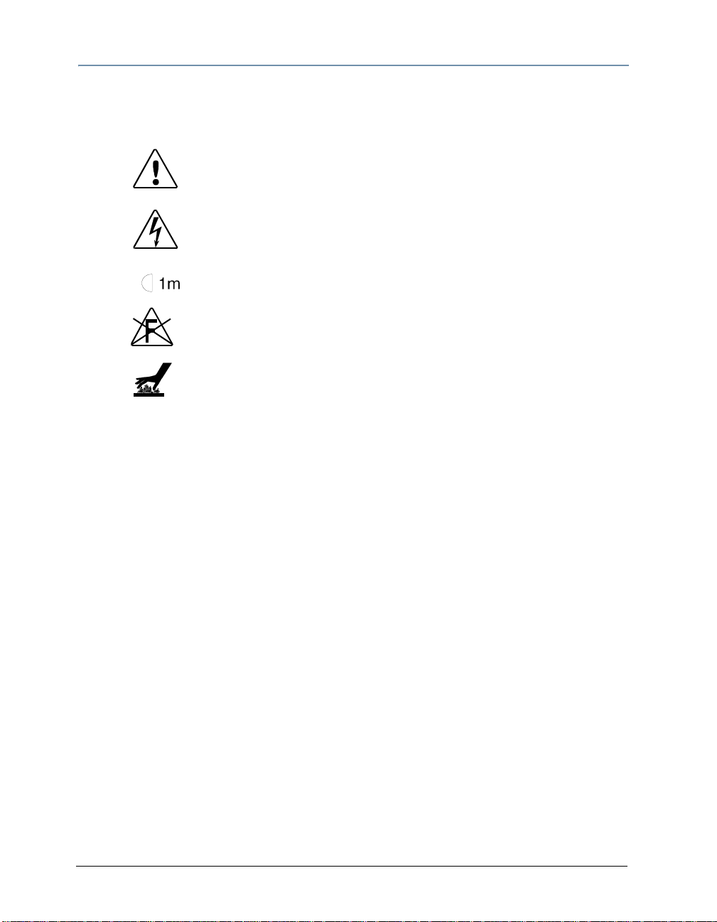
Symbols
The following international caution and warning symbols appear in margins throughout this manual to
highlight messages.
CAUTION: This symbol appears adjacent to Caution
messages. Not heeding these messages could result in
personal injury and/or damage to equipment.
WARNING: This symbol appears adjacent to high
voltage warning messages. Not heeding these
messages could result in serious personal injury.
This symbol indicates the minimum focus distance
from a combustible object.
This symbol cautions against mounting the fixture on a
flammable surface.
This symbol indicates that, while operating, equipment
surfaces may reach very high temperatures. Allow the
fixture to cool before handling.
Fog Machine Warning
Like all high quality video projection units, the DL.2 fixture must be kept protecte d from excessiv e amounts of
glycol fog, mineral oil, and smoke. The DL. 2 fixture incorpor ates two-stage air filtering to reduce these risks to
a minimum; however, the user must follow these guidelines to ensure continued operation of the fixture:
• Air filters (both fixture and projector) should be ch ecked and clean ed on a regular basis. When used in
a closed or fixed environment where fog or haze is used, we recommend at least a weekly check.
• Do not situate DL.2 fixtures in areas of high fog density such as directly in front of a fog machine or
mineral oil hazer.
• Minimize the exposure of DL.2 fixtures to both glycol fog and mineral oil.
The DL.2 fixture is a highly complex and sensitive electro-optical device and care and thought in how it is
used, rigged, and positioned will maximize the product’s life and your investment.
Failure to follow these guidelines and carry out regular maintenance will void the warranty.
Packaged Media Notice:
Any use of this product other than consumer personal use in any manner that complies with the
MPEG-2 Standard for encoding video information for packaged media is expressly prohibited
without a license under applicable patents in the MPEG-2 patent portfolio, which license is
available from MPEG LA, L.L.C., 250 Steele Street, Suite 300, Denver Colorado 80206.
Warranty Information
Limited Warranty
Unless otherwise stated, your product (excluding the lamp) is covered by a one year parts and labor limited
warranty. The lamp warranty for Christie projectors is 120 days or 500 hours whatever comes first. It is the
owner’s responsibility to furnish receipts or invoices for verification of purchase, date, and dealer or
distributor. If purchase date cannot be provided, date of manufacture will be used to determine warranty
period.
vi DL.2 Digital Light User Manual
Page 7

Returning an Item Under Warranty for Repair
It is necessary to obtain a Return Material Authorization (RMA) number from y our de aler o r po int of p urch ase
BEFORE any units are returned for repair. The manufacturer will make the final determination as to whether or
not the unit is covered by warranty.
Any Product unit or parts returned to High End S ystems must be packaged in a suitabl e manner to ensure the
protection of such Product unit or parts, and such pack age shall be clearly and prominen tly marked to indicate
that the package contains returned Product units or parts and with an RMA number. Accompany all returned
Product units or parts with a written explanation of the alleged p roblem or mal function. Ship retur ned Product
units or parts to: 2105 Gracy Farms Lane, Austin, TX 78758 USA.
Note: Freight Damage Claims are invalid for fixtures shipped in non-factory boxes and packing materials.
Freight
All shipping will be paid by the purchaser. Items under warranty shall have return shipping paid by the
manufacturer only in the Continental United States. Under no circumstances will freight collect shipments be
accepted. Prepaid shipping does not include rush expediting such as air freight. Air freight can be sent
customer collect in the continental United States.
REPAIR OR REPLACEMENT AS PROVIDED FOR UNDER THIS WARRANTY IS THE EXCLUSIVE REMEDY OF THE
CONSUMER OTHER THAN THE LIMITED WARRANTY STATED ABOVE. HIGH END SYSTEMS, INC. MAKES NO
WARRANTIES, EXPRESS OR IMPLIED, WITH RESPECT TO ANY PRODUCT, AND HIGH END SPECIFICALLY
DISCLAIMS ANY WARRANTY OF MERCHANTABILITY OR FITNESS FOR A PARTICULAR PURPOSE. HIGH END
SHALL NOT BE LIABLE FOR ANY INDIRECT, INCIDENTAL OR CONSEQUENTIAL DAMAGE, INCLUDING LOST
PROFITS, SUSTAINED OR INCURRED IN CONNECTION WITH ANY PRODUCT OR CAUSED BY PRODUCT
DEFECTS OR THE PARTIAL OR TOTAL FAILURE OF ANY PRODUCT REGARDLESS OF THE FORM OF ACTION,
WHETHER IN CONTRACT, TORT (INCLUDING NEGLIGENCE), STRICT LIABILITY OR OTHERWISE, AND
WHETHER OR NOT SUCH DAMAGE WAS FORESEEN OR UNFORESEEN.
Warranty is v oid if the produ ct is misused, damaged, mod ified in any w ay, or for unauthorized repairs or parts.
This warranty gives you specific legal rights, and you may also have other rights specific to your locality.
What You Should Know About Copyright
The following FAQ can help you understand copyright laws and how they apply to content used
with the DL.2 fixture
By Suzy Vaughan Associates for High End Systems.
I want to use a film clip from “When Harry Met Sally” in a promotional piece advertising my
services. What do I have to do to be able to do that?
First of all, you need to obtain permission to use the clip from its owners. The clip is considered intellectual
property , j ust as though it we re your car or some softw are code dev eloped by and b elonging t o Microsoft. This
is because the U.S. Copyright Act gave creators of literary works (which include books, films, television
programs, art works, still photos and musical compositions and recordings) the right to sell or license these
works and to make money from them for the period of the copyright.
But what about public domain material? I heard that lots of material is in the public domain and
can be used for free.
Once the copyright runs out, the creative work falls into the public domain and can be used freely by anyone
without payment or licensing. If the work is not public domain, it is considered literary property. The
Copyright Act provides substantial penalties for copyright infringement ranging from $10,000 for accidental
infringement to $250,000 for willful infringement. However, contrary to popular belief, there really is not that
much material in the public domain so this approach will limit you creatively.
DL.2 Digital Light User Manual vii
Page 8

What if I want to use a clip in a public performance? It's not being filmed or taped. Surely I don't
need permission for that?
Public gatherings require clearance whenever copyrighted data is projected to audiences, or for any use other
than just personal viewing. Concerts, trade shows, industrial shows, parties and raves are all examples of
public performance and permission must be obtained.
Suppose I want to use a still photo or a magazine cover or a television clip? Do I have to obtain
permission for them too?
Yes, they are also copyrighted works, whose owners must grant a license for their usage.
Do I need any other permissions to use this material?
In many cases you do. You may need to obtain permission to use the appearance of actors who appear in the
clip as well as pay the writers and directors of the film that your clip comes from.
What about music? I hear you can use 8 bars for free.
8 bars for free is a fallacy that has been passed around as a fact for a long period of time. However, it isn't
true. Both musical compositions and records require licensing and payment.
What about High End Systems material included with the DL.2 fixture? Do I have to clear that?
No. High End Systems has worked to provide clearance for the content that is pr o vided with the DL.2 fixtu re.
Any materials you received directly from HES with the purchase of a new DL.2 fixture have already been
properly licensed for your use in shows and presentations. That does not, however, license you to sell this
content separately from DL.2 fixture. Also, please be sure that any new content you obtain from outside
sources is properly cleared for public presentation.
This sounds really difficult and I don't know how to do it? What do I do to properly license
copyrighted material?
You need to consult with a Content Clearing House or with a properly licensed Intellectual Property Attorney.
Content clearinghouses are typically less expensive to work with and have well established industry relations
that can result in cost savings. High End Systems uses and highly recommends Suzy Vaughan Associates.
Suzy Vaughan Associates has 20 years of e xperience in clear ing clips, talent, and music for use in any nu mber
of venues. Their clients include Barbara Streisand, Michael Jackson, and The Emmys among other shows.
You can obtain more information about Suzy Vaughan Associates' services by calling 818-988-5599 or
emailing info@suzyvaughan.com. Their website is www.suzyvaughan.com. Suzy Vaughan is also an attorney
specializing in intellectual property issues.
How much does it typically cost to license copyrighted material?
The answer depends entirely on what material you want to use and how you plan to use it. Prices can range
from hundreds of dollars for photography content to thou sands of dollars for a high ly desirab le film/video clip .
Since price is content-sensitive, the best thing to do is to contact a clearinghouse like Suzy Vaughan
Associates and let them find out for you.
viii DL.2 Digital Light User Manual
Page 9

Table of Contentsii
DL.2 Digital Lightwith Collage™ Software..................................................ii
Contacting High End Systems® ......................................................................ii
Patents ...................................................................................................... iii
Declaration of Conformity ............................................................................. iv
Product Modification Warning .........................................................................v
FCC Information ...........................................................................................v
Important Safety Information .........................................................................v
Symbols ..................................................................................................... vi
Fog Machine Warning ................................................................................... vi
Packaged Media Notice: ................................................................................ vi
Warranty Information ................................................................................... vi
What You Should Know About Copyright .........................................................vii
Chapter 1: Product Overview
This chapter describes the features and specifications of the DL.2 fixture and
the Content Management Application software.
Features ........................................................................................................ 1
System .......................................................................................................1
Graphics Engine ...........................................................................................2
Content Management Application ....................................................................2
Hardware ....................................................................................................3
Related Products and Optional Accessories ................................................... 4
Chapter 2: Setup and Configuration
Hardware setup includes mounting, connecting to power and Ethernet and DMX
linking. Software setup includes launching the Content Management
Application (CMA) and configuring the fixture for DMX control.
Hardware Setup ............................................................................................ 5
Unpacking the Fixture ...................................................................................5
Hardware Components ..................................................................................6
Connection Ports .......................................................................................6
Pan and Tilt Locking ...................................................................................7
Attaching a Power Cord Cap ...........................................................................7
Installing a Line Cord Cap - U.K. Only ..........................................................7
Vatic Fitter Heads Information - Danmark .....................................................7
Mounting the Fixture .....................................................................................8
Fog Machine Warning .................................................................................8
Mounting the Fixture Upright .......................................................................9
Truss Mounting .........................................................................................9
DL.2 Digital Light User Manual ix
Page 10

Linking DL.2 Fixtures .................................................................................. 10
Setting up a Standard DMX Link ................................................................ 10
Setting up an Ethernet Fixture Link ............................................................ 11
Linking Configurations .............................................................................. 11
Powering On the Fixture .............................................................................. 12
Homing the Fixture .................................................................................. 13
The DL.2 Menu Display Panel .................................................................... 13
Software Setup ........................................................................................... 14
Installing and Launching the Content Management Application (CMA) ................ 14
Verifying and Upgrading Fixture and CMA Software ......................................... 15
Configuring DL.2 Fixtures ............................................................................ 16
Setup Configuration Using the Menu System ............................................... 16
Setup Configuration Using the CMA ............................................................ 17
DMX Control Setup ..................................................................................... 18
Patching the DL.2 Fixture to a Wholehog Console ......................................... 18
Viewing Output ....................................................................................... 18
Shutting Down the Fixture .......................................................................... 19
Recommended Shutdown Options ................................................................. 19
Placing Fixture in Road Case ....................................... .. .. ........................ .. .. .19
Chapter 3: The DL.2 Menu System
You can use the DL.2 fixture’s Menu System to configure the fixture, review
diagnostic feedback, and view content information.
Menu Panel Components ............................................................................. 21
LCD Display Adjustment Buttons .................................................................. 22
LCD Display Power Button ........................................................................ 22
LCD Display Menu Options and Selection .................................................... 22
Navigating the Menu ................................................................................... 23
DL.2 Menu Options ...................................................................................... 24
Menu Screen Descriptions ........................................................................... 27
DMX Tab .................................................................................................. 27
DMX_Control Screen ............................................... ........................ ......... 27
DMX_Protocol Tab ................................................................................... 28
DMX_Protocol_Motion Screen .................................................................... 28
DMX_Protocol _Global Screen ................................................................... 28
DMX_Protocol _Obj Screens ...................................................................... 28
DMX_Raw Screen .................................................................................... 29
Set Tab ...................................... ............................................................... 30
Set_Fixture Screen .................................................................................. 30
Set_Projector Screen ............................................................................... 31
File Screen ................................................................................................ 32
x DL.2 Digital Light User Manual
Page 11

Test Tab .................................................................................................... 33
Test_Home Screen ..................................................................................33
Test_Self Test Screen .............................................................................. 33
Info Tab .................................................................................................... 34
Info_Hours ............................................................................................. 34
Info_Version Screen ................................................................................ 34
Info_Status Tab ......................................................................................34
Reset Screen ............................................................................................. 35
Chapter 4: DMX Programming Basics and Quick Start
If you are new to DMX programing, this chapter will give you a brief overview on
programming Axon and DL.2 media servers followed by a example of using a
Wholehog console to patch and display output from an Axon or DL.2 media server.
DMX Programming Overview ...................................................................... 37
DMX512 Links .......................................... ........................ ........................ ..37
8-bit vs. 16-bit DMX Parameters ................................................................... 37
Determining a DMX Start Channel .................................................................38
DL.2 Protocol Levels ....................................................................................39
Axon Protocol Levels ...................................................................................40
Lighting Console Tips .................................................................................. 41
Fixture Libraries: ........................................................................................ 41
Patching DL.2 Fixtures and Axon Media Servers .............................................. 41
DMX Output Displays ..................................................................................41
Wholehog III Programming Notes .............................................................. 42
Play Speed ................................................................................................ 42
Mask Strobe .............................................................................................. 42
Play Modes (Opacity) ..................................................................................42
CMY ..........................................................................................................42
Control Channel Functions ...........................................................................42
Quick Start Axon and DL.2 Control with a Wholehog Console ...................... 43
Chapter 5: Tutorials
Five simple lessons get you started programming DL.2 and Axon media servers
with a Wholehog 3 or other DMX console.
Fixture Set-up (DL.2 Media Servers) ....... .................................................... 45
Lesson 1: Cross Fading Between Graphic Objects ....................................... 46
Define Graphic Object 1 ........................................................................... 46
Add the DL.2 logo as Graphic Object 2 .......................................................46
Define Graphic Object 3 ........................................................................... 46
Create Crossfade Cues ............................................................................. 46
Lesson 2 - Working with Multiple Graphic Objects ...................................... 47
Apply Transparency Effects ...................................... .. .. ........................ ........47
DL.2 Digital Light User Manual xi
Page 12

Lesson 3 - Girt, the Fire Breathing Lizard .................................................... 48
Define Graphic Object 1 .......................................................................... 48
Define Graphic Object 2 ........................................................................... 48
Define Graphic Object 3 ........................................................................... 49
Lesson 4: 3-D Objects, Rotation, Wobbulation, and Glow. ........................... 50
Define Graphic Object 1 ........................................................................... 50
Define Graphic Object 2 ........................................................................... 50
Adjust this effect with the Modifer paramet ers. ............................................ 51
Lesson 5: Viewpoint .................................................................................... 52
Define Graphic Object 1 ........................................................................... 52
Define Graphic Object 2 ........................................................................... 52
Define Graphic Object 3 ........................................................................... 52
Apply a Global Solarize Effect .................................................................... 53
Adjust Global Viewpoint Mode ................................................................... 53
Chapter 6: Graphics Engine Overview
DL.2 fixture’s and Axon Media servers both use the same graphic engine
software to control content selection, playback, and 3-D Object and Global
manipulation.
Axon Protocol Options ................................................................................ 55
Image Optimizing Controls ......................................................................... 55
Graphics Control Hierarchy ......................................................................... 56
Graphics Engine Function Flow ..................................................................... 57
Graphics Engine Functions .......................................................................... 58
Object Graphic Functions ............................................................................. 58
Global Functions ......................................................................................... 58
Making Graphics Effect Choices ................................................................... 58
Chapter 7: Graphic Functions: Defining Content
Each Graphic Object’s content is composed of a 3-D object overlaid with a
media file. This chapter outlines how to select an image’s object and media file
components as well as define the video segment and its playback.
Selecting Content ........................................................................................ 59
How Content is Organized ............................................................................ 59
Selecting Content ....................................................................................... 59
Content Selection Parameters ..................................................................... 60
Object .................. ...... .... .... .... ...... .... .... ... ...... .... .... ...... .... .... .... ...... .... .... .... 60
Media Folder .............................................................................................. 61
Media Folder Descriptions ......................................................................... 61
Media File .................................................................................................. 62
xii DL.2 Digital Light User Manual
Page 13

Defining a Media File Segment .................................................................... 63
In Frame and Out Frame Parameters .............................................................63
Segment Selection Examples ........................................................................63
Defining Playback ....................................................................................... 64
Playback Mode ...........................................................................................64
Playback Speed .......................................................................................... 65
Chapter 8: Graphic Functions: Rotation, Position, Scale
You can independently control each Graphic Object’s rotation direction and
speed; along with it’s position and scale in x, y, and z axis directions.
Rotating a 3-D Object .................................................................................. 67
Rotation Parameters ................................................................................... 69
X Rotation ................................................................................................. 69
Y Rotation .................................................................................................70
Z Rotation ................................................................................................. 71
Scaling the Object ....................................................................................... 72
X Scale .....................................................................................................72
Y Scale ......................................................................................................73
Z Scale .....................................................................................................74
Changing Object Position ...... ...................................................................... 75
X Position ..................................................................................................75
Y Position ..................................................................................................75
Z Position ..................................................................................................77
Chapter 9: Graphic Functions: Opacity and Effects
You can adjust opacity and apply a variety of color mixing and geometric effects
to each individual Graphic Object.
Opacity ....................................................................................................... 79
Visual Mode ................................................................................................. 80
Visual Mode Options .................................................................................... 82
Color to B/W ..............................................................................................82
Content Optimization .................................................................................. 82
Chroma Shift ............................................................................................. 83
Drop Shadow ............................................................................................. 84
Exposure Control ........................................................................................ 85
Faux LED ...................................................................................................86
Faux Tile ...................................................................................................87
Film Roll ....................................................................................................88
Fire Gradient .............................................................................................. 88
Fuzzifier .................................................................................................... 89
Gray maker 1 .............................................................................................90
Gray maker 2 .............................................................................................91
DL.2 Digital Light User Manual xiii
Page 14

Invert Black and White, Keep Color ............................................................... 92
Negative Art .............................................................................................. 93
Pan and Scan ............................................................................................. 94
Pixelate .............. .................... ................... .................... ...................... ...... 95
Posterizer .................................................................................................. 96
Push to Red ............................................................................................... 97
Push to Sepia ............................................................................................. 98
ShakeNBake .............................................................................................. 99
Texture Mixing ........................................................................................... 99
Zoom Blur ................................................................................................. 99
Effect 1 Mode and Effect 2 Mode ............................................................... 100
Chapter 10: Graphic Functions: Synchronizing Content
After designating a master fixture, you can synchronize the content of other
Axon or DL.2 fixtures to any Object on the master in terms of playback time,
rotation or both.
Synchronization Overview ........................................................................ 105
Fixture Identification .......................................... .. ........................ ..............105
Playback Timing ........................................................................................105
Synchronization Parameters ..................................................................... 106
Sync To ...................................................................................................106
Sync Mode ................................................................................................106
Chapter 11: Global Functions
Global Graphic controls affect the comp osite image created by defining two or
three separate object graphics. You can adjust intensity, define masks, select
a point in space to view the composite image, and control keystone correction.
Global Intensity ........................................................... .......... ................... 107
Global Effect Mode 1 and Effect Mode 2 .................................................... 108
Global Control ........................................................................................... 112
Shutdown and Reset Options ......................................................................112
Four-in-One Control Option .........................................................................112
On-Screen Frame Statistics .........................................................................113
Masking Control ........................................................................................ 114
Mask Shape Select and Strobing ..................................................................114
Mask Shapes .........................................................................................114
Strobing Mask Shapes .............................................................................114
Mask Size .................................................................................................115
Mask Edge Fade ........................................................................................116
Image Edge Fade ......................................................................................117
Keystone Correction Parameters ....... ......... ............................................... 118
X Ratio .................. .................................................................................... 119
xiv DL.2 Digital Light User Manual
Page 15

Y Ratio ...................................................................................................... 119
Global Viewpoint Mode .............................................................................. 120
Perspective View, Spherical Coordinates ...................................................... 120
Perspective View, Cartesian Coordinates ...................................................... 120
Orthogonal View, Cartesian Coordinates ...................................................... 120
Viewpoint Position X ............. .................................................................... 121
Viewpoint Position Y ................................................................................. 121
Viewpoint Position Z (Zoom) ..................................................................... 121
Chapter 12: Global Functions: Collage Generator™ Effect
Using the Collage™ Generator effect option lets you configure multiple media
server outputs to display a single image in arrays up to 8 x 8.
Panorama Collage™ Configurations ..................................... ...................... 124
Computing Collage Specifications ................................................................ 124
Example ............................................................................................... 124
Central Panorama Collage Specifications ................................................... 125
Horizontal Panorama Collage Specifications ............ ............................ ....... 126
Vertical Panoramas Collage Specifications ................................................. 128
Configuring the Collage Generator ............................................................ 131
Adjusting the Collage Array ........................................................................ 131
Collage Setup Example .............................................................................. 133
Mapping a Collage to a Spherical Surface .................................................. 134
Spherical Mapping Setup Guide .................................................................. 134
Before You Begin ................................................................................... 134
Mapping Two Outputs to a Sphere ........................................................... 134
Spherical Mapping Tips ........................................................................... 136
Creating Custom Content for the Collage Generator Effect ........................ 137
Collages Using Live S-Video Input ................................................ ............. 137
Chapter 13: Effect Mode Options Descriptions
Effects can be applied to the Media File content (texture) mapped onto a 3-D
object. Multiple Color and Geometric options are available in Effect Mode
parameters for both individual Graphic object and Global control.
Effect Mode Color Options ......................................................................... 140
All or Nothing ........................................................................................... 140
Background Color ..................................................................................... 140
Background Color Cycle ............................................................................. 140
Chromakey .............................................................................................. 141
Chromakey Coarse ................................................................................ 141
Chromakey Fine .................................................................................... 141
Chromakey Medium ............................................................................... 141
Modifier Parameters ............................................................................... 141
DL.2 Digital Light User Manual xv
Page 16

Chromakey , Inverse .................................................................................142
Chromakey Coarse, Inverse .....................................................................142
Chromakey Fine, Inverse .........................................................................142
Chromakey Medium, Inverse ....................................................................142
Modifier Parameters ................................................................................142
CMY .......... ..................................................................................... .........143
CMY Add All Pixels .....................................................................................143
CMY Add Non-black Pixels ...........................................................................143
Color Cycle .......................................... .. ... ........................ ........................144
Color DeConverge .......................... .. ......................... .. ........................ .. ....144
Colorize Gray Scale ....................................................................................144
Color to Alpha ...................................... ......................... .. .. ........................145
Color to Alpha, Inverted .............................................................................145
DotP and Resample ....................................................................................145
Edge Fade Color ........................................................................................145
Glow ...................... .................... ..................... .................... ..................... 146
Glow Color Cycle .......................................................................................146
Intensity Key ............................................................................................146
Mask Color ...............................................................................................147
Mask Color and Edge Fade Color ..................................................................147
RGB Add, All Pixels ....................................................................................147
RGB Add2, All Pixels ..................................................................................148
RGB Add to Non-black Pixels .......................................................................148
RGB Invert ...............................................................................................148
RGB Invert and Swap to BRG ......................................................................149
RGB Invert and Swap to GBR ......................................................................149
RGB Scale ................................................................................................149
RGB Swap to BGR ......................................................................................150
RGB Swap to BRG ......................................................................................150
RGB Swap to GBR ......................................................................................150
RGB Swap to GRB ......................................................................................151
RGB Swap to RBG ......................................................................................151
Scan Line .................................................................................................151
Solarize ...................................................................................................152
Solarize 1 ..............................................................................................152
Solarize 2 ..............................................................................................152
Solarize 3 ..............................................................................................152
Solarize 4 ..............................................................................................152
Solid Color RGB .........................................................................................152
Geometric Effect Options .......................................................................... 153
Cartoon Edge ...........................................................................................153
Collage Generator ......................................................................................153
xvi DL.2 Digital Light User Manual
Page 17

Chroma Shift ........................................................................................... 154
Curved Surface Support ....................... ......................... .. .. .. .. .................... 154
Downward Vertical Streaks ........................................................................ 156
Drop Shadow ........................................................................................... 157
Edge Detect Black and White ...................................................................... 157
Edge Detect Color ..................................................................................... 158
Faux LED ................................................................................................. 158
Faux Tile ................................................................................................. 159
Film Roll .................................................................................................. 159
Framing .................................................................................................. 160
Framing Shutter Emulation ..................................................................... 160
Fuzzifier .................................................................................................. 162
Gaussian Blur ........................................................................................... 162
Horizontal Mirror ...................................................................................... 163
Image Scale and Rotate ............................................................................ 163
Magnifying Lens ....................................................................................... 164
Magnifying Lens 2 ..................................................................................... 164
Mattes .................................................................................................... 165
Pan and Scan ........................................................................................... 167
Picture in Picture ...................................................................................... 167
Pixelate ................................................................................................... 168
Pixel Twist ............................................................................................... 168
Raindrop ................................................................................................. 168
ShakeNBake ............................................................................................ 169
Sinewave, Circular .................................................................................... 169
Sinewave, Circular w/X-axis Wobbulation .................................................. 169
Sinewave, Circular w/Y-axis Wobbulation .................................................. 169
Sinewave, Circular w/Z-axis Wobbulation .................................................. 169
Sinewave, Horizontal ................................................................................ 170
Sinewave, Horizontal w/X-axis Wobbulation .............................................. 170
Sinewave, Horizontal w/Y-axis Wobbulation .............................................. 170
Sinewave, Horizontal w/Z-axis Wobbulation .............................................. 170
Sinewave, Vertical ................................................................................... 170
Sinewave, Vertical w/X-axis Wobbulation .................................................. 170
Sinewave, Vertical w/Y-axis Wobbulation .................................................. 170
Sinewave, Vertical w/Z-axis Wobbulation .................................................. 170
Slats ....................................................................................................... 171
Vertical Slats ........................................................................................ 171
Horizontal Slats ..................................................................................... 171
DL.2 Digital Light User Manual xvii
Page 18

Spherical Mapping .....................................................................................172
Spherical Mapping, Outside ......................................................................172
Spherical Mapping, Inside ........................................................................172
Modifier Parameter Adjustments ...............................................................172
Texture Mixing ..........................................................................................174
Texture Ripple, Asymmetrical Circular .........................................................175
Texture Ripple, Circular ..............................................................................175
Texture Ripple, Horizontal ...........................................................................176
Texture Ripple, Vertical ..............................................................................176
Tiling .......................................................................................................177
Transparent Wipes..................................................................................... 177
Zoom Blur ................................................................................................178
Chapter 14: Fixture Motion Functions
This chapter describes mechanical control for the DL.2 fixture with it’s internal
projector.
Pan and Tilt ............................................................................................... 179
Dimmer .................................................................................................... . 179
Focus ........................................................................................................ 179
Zoom ......................................................................................................... 179
MSpeed (Motor Speed) .............................................................................. 180
Control Function Options .......................................................................... 180
Fixture Operations .............................. .. .. ... ........................ ........................180
Projector Control .......................................................................................181
Control Parameter Projector Options .........................................................181
Using the Internal Projector’s Menu ..........................................................182
Chapter 15: Live Video Input and Control
The DL.2 graphics engine can receive video from an external source or its own
integrated digital video camera equipped with an infared illuminator to provide
a direct digital video feed option.
Live Video Sources .................................................................................... 183
Internal Camera ................................. .. .. ... ........................ .. .. ....................183
Other Video Sources ..................................................................................183
Live Video Connection Options .................................................................. 184
Configuring the Video Input Source .......................................................... 184
Sending the Camera Feed to Camera Out .................................................. 185
Controlling the Internal Camera Input ...................................................... 185
Camera Zoom ...........................................................................................185
Camera Focus ...........................................................................................185
IR Illuminator ...........................................................................................185
Camera Shutter ........................................................................................186
xviii DL.2 Digital Light User Manual
Page 19

White Balance Mode ................................ .. .. ........................ .. .................... 186
Orientation .............................................................................................. 186
Camera Effects ......................................................................................... 186
Chapter 16: Content Management Application (CMA)
A Content Management Applicati on (CMA) running on an Axon media server or
a computer connected through an Ethernet network gives you remote control
of content, software and configuration management functions.
Launching the CMA ................................................................................... 188
Installing the CMA on Your Computer .......................................................... 188
Launching the CMA on Axon ....................................................................... 189
Auto Discovery ......................................................................................... 189
Fixture Identification ................................................................................. 190
The Management Client Window ............................................................... 190
Viewing Server Identification Information .................................................... 190
Client Window Content Organization ............................................................ 191
Preloaded Stock Content ........................................................................ 192
Custom User Content ............................................................................. 192
Media Files ........................................................................................... 192
3D Object Files ...................................................................................... 192
Viewing Server Configuration Data .............................................................. 192
Viewing Content ....................................................................................... 193
Viewing Folders ..................................................................................... 193
Viewing Files ......................................................................................... 193
Managing User Content ............................................. ................................ 194
Naming and Deleting User Content Files and Folders ..................................... 194
Assigning DMX Values to User Content ........................................................ 195
Assigning DMX Values Automatically ........................................................ 195
Editing User Content DMX Values ............................................................. 195
Valid DMX Values .................................................................................. 195
Moving User Content Files and Folders ......................................................... 196
Downloading Content from a Media Server to Your Local Drive .................... 197
Uploading Content from Your Local Drive to a Media Server ......................... 197
Moving Files Between Fixtures ................................................................. 198
Archiving User Content ............................................................................. 199
Using Local Archives to Prepare Content Offline ............................................ 199
Creating a Local Archive ............................................................................ 199
For CMA Running Windows XP ................................................................. 199
For CMA Running Mac OS 10.4 ................................................................ 200
Creating Content Backup Archive ................................................................ 200
Deploying a Content Archive ...................................................................... 200
Cloning User Content ................................................................................ 201
DL.2 Digital Light User Manual xix
Page 20

Deleting Content ....................................................................................... 202
DMX Summary .......................................................................................... 202
Upgrading Software .................................................................................. 202
Verifying Software Versions ........................................................................202
Upgrading the CMA Software .......................................................................203
Upgrading Server Software .........................................................................203
Viewing and Editing Server Configuration ................................................. 204
Viewing Fixture Configuration Values ............................................................205
Editing Configuration Values .......................................................................205
Configuration Example ...............................................................................206
Configuration Options ................................................................................207
DL.2 Configuration Options ...................................................... ................207
Axon Configuration Options .....................................................................210
Chapter 17: Maintenance and Troubleshooting
This chapter includes information on replacing parts, cleaning the fixture, and
some basic troubleshooting procedures.
Pan and Tilt Locking .................................................................................. 211
Maintaining the Filtering System .............................................................. 212
Filter Warnings ..........................................................................................212
Cleaning and Replacing Filters .....................................................................212
Cleaning the Base Housing Filter ..............................................................213
Replacing the Fixture Filter ......................................................................213
Cleaning the Internal Projector Filter .........................................................214
Replacing the Lamp .................................................................................. 215
Replacing the Fuse .................................................................................... 216
Cleaning or Replacing the Front Window .................................................. 216
Replacing Motor Driver Boards .................................................................. 217
Fixture Head Driver Board ..........................................................................218
Replacing Fixture Base Driver Board .............................................................218
Troubleshooting ....................................................................................... . 219
Button Shortcut Commands ........................................................................219
Status Message Menu Display .....................................................................219
Button Action .........................................................................................220
Inactivity Timer ......................................................................................220
Supported Error/Warning Messages ..........................................................220
System State LEDs ....................................................................................221
Board LED States ......................................................................................222
General Troubleshooting Suggestions ...........................................................222
Frequently Asked Questions ........................................................................224
xx DL.2 Digital Light User Manual
Page 21

Chapter 18: Restoring the System
You can perform a system restore on the Axon or DL.2 Server with your System
Restore CD.
Hardware Requirements ........................................................................... 225
Performing the System Restore ................................................................ 225
Appendix A: DL.2 and Axon DMX Protocol
DL.2 fixtures and Axon Media Servers utilize the same DMX protocol except that
DL.2 fixtures include channels for motion and camera control. This table describes
the Standard, Dual and Single Protocol for DL.2 fixtures and Axon Media Servers.
Protocol Table ........................................................................................... 229
Appendix B: MSpeed Conversion Table
This table lists the MSpeed (motor) movement times and their corresponding
DMX controller values.
Appendix C: Custom User Content
There are several considerations to keep in mind when creating custom content
to control with the DL.2 graphics engine software.
Preparing Custom Content .................................................................... .... 289
Encoder Selection ..................................................................................... 289
Creating 3-D Objects ................................................................................. 290
Managing Custom Content ........................................................................ 290
Appendix D: DL.2 Specifications
Fixture mechanical, electrical, optical and component sp ecifications are listed.
Mechanical ................................................................................................ 291
Electrical Specifications ............................................................................ 292
Projector Specifications .......................... .................................................. 292
Camera Module Specification .................................................................... 292
Environmental Specifications .................................................................... 292
Cable and Connector Specifications ........................................................... 293
Video Connectors: .................................................................................... 293
Peripheral/Network Connectors: ................................................................. 293
DMX and RS-485 Projector Link .................................................................. 293
Appendix E: Safety Information
Appendice E: Importantes Informations Sur La Sécurité ................................. 296
Anhang E: Wichtige Hinweise Für Ihre Sicherheit .......................................... 297
Apéndice E: Información Importante De Seguridad ............ ........................... 298
Appendice E: Importanti Informazioni Di Sicurezza ....................................... 299
Vigtig Sikkerhedsinformation ...................................................................... 299
DL.2 Digital Light User Manual xxi
Page 22

xxii DL.2 Digital Light User Manual
Page 23

Chapter 1:
Product Overview
This chapter describes the features and specifications of the DL.2 fixture
and the Content Managemen t Ap plication software.
The DL.2 (Digital Light 2) fixture merges video projection and automated lighting technologies
with a DMX controllable digital media server housed in a mo ving yoke fixture. The built- in 32-bit
Graphics Engine utilizes Windows XP Embedded and DirectX application programming
interface to provide extensive image control of up to three 3-D graphic objects.
DL.2 fixtures use DMX512 protocol to control hardware functions like pan, tilt, and zoom, as well
as media control functions including loading images and movies and mapping them onto 3-D
graphical objects. The internal graphics engine lets you manipulate position, scale, rotation,
apply visual effects and color mix each graphic object . You can create and control up to three of
these objects and then apply global effects to the com p osite image.
The DL.2 fixture provides a fully equipped internal digital camera and IR illuminator to input live
video to its own graphic engine or to another DL.2 fixture or device. While combining camera
and light from the same source to allow a unique point of view, the camera also features optical
and digital zoom, frame rate and invert effects as well as freeze frame, color negative and
grayscale conversion effects. The ability to point the camera at it’s own projection combined
with adjustable zoom creates unique realtime video feedback and “hall of mirrors” effects. The
IR illuminator allows visibility, focusing, and fading in blackout situations.
The Content Management Application (CMA) runs on your workstation or laptop computer
and communicates with DL.2 fixtures over an Ethernet network. The CMA lets you remotely
upload, move and clone content files, configure fixtures, and upgrade software.
Features
System
• DL.2 software based on Windows XP Embedded and DirectX technology
• Powerful Content Management and Configuration software can remotely ma nage multiple
DL.2 fixtures
• Integrated Sony camera with Super HAD technology and infrared illuminator provides live
video input and output from fixture location
• Supports importing of custom content including: 3 D objects, media files, still images
• DMX512 and Art-Net support
• Remote software upgrade capability
• Royalty-free stock digital art collection features over 1000 lighting-optimized files
DL.2 Digital Light User Manual 1
Page 24

CHAPTER 1
Product Overview
• RGBHV and S-Video connections accept a wide range of media device inputs
• Collage™ software included with graphics engine
Graphics Engine
• Simultaneous playback of three discrete media streams on separate 2D/3D objects
• Image Optimizing Controls let you adjust both Black Level and Contrast for each cue and for
each image
• 30 Object parameters give you graphic controls for each individual media stream including:
— A choice of multiple play modes and play speeds
— The ability to define any segment of a video loop including Scrub capability
— Multiple color mixing and visual effects that can be combined any way you choose
— Variable Opacity to allow for crossfading or dissolves between media streams
— Full control of image Rotation, Positioning and Scaling on X, Y and Z axes
— Visual Modes that let you control black level and contrast to optimize content
— Video input or camera capture you can apply to 2d/3d objects
• 35 Global parameters provide graphic controls to the composite image created by up to 3
media streams
— Collage Generator™ technology configures multiple media server outputs to display a
single image in arrays up to 8 x 8.
— Curved Surface Support corrects for shape distortions that occur when you project onto
surfaces that aren’t flat.
— Intensity overlays the opacity control to provide system-wide intensity level
— Overall image Color Mixing applied to composite media stream image
— Color Effects including edge colors allow for combined image color mixing
— Multiple Mask selections with edge fading and strobe effects
— Edge fading for creating montages
— Keystone correction on output projection
— Viewpoint controls provide ability to c hange viewing angle/perspective on images
• Multiple modes for synchronizing content playback on multiple media servers linked through
an Ethernet network.
Content Management Application
• Available for Windows and Mac operating systems
• Communicates with other Axon and DL.2 media servers over an Ethernet network
• Uploads and downloads custom digital content to DL.2 fixtures
• Configures Axon and DL.2 media servers
• Updates software including content, applications, and operating system to Axon and DL.2
media servers.
2 DL.2 Digital Light User Manual
Page 25

CHAPTER 1
Product Overview
Hardware
• 17 Motion Parameters for mechanical fixture control include:
— Mechanical Iris adjustment to full black-out
— 400-degree Pan and 240-degree Tilt movement
— DMX control of projector zoom and focus
— DMX control of camera functions
• Integrated digital camera feeds digital video capture directly into the graphic engine that
provides:
— Optical + digital zoom to increase image up to 216×
— Options for 1-30 frame captures / sec
— Vertical and/or Horizontal image inversion
— Black and White, Color Negative and Freeze Frame effects
— White Balance including Red and Blue gain control
• Infrared illuminator allows video capture even in blackout settings
• Remote video input and output switching let you select live video from external source
including another DL.2 fixture's camera feed.
• Full color display and menu functions
• Powered by a 3.2GHZ Pentium 4 HT processor with an ATI X850XT Graphics Processor
• Gigabit Ethernet for fast content uploading and multiple fixture synchronization
• Mounting system provides multiple or ientation options
DL.2 Digital Light User Manual 3
Page 26

CHAPTER 1
Product Overview
Related Products and Optional Accessories
The following table lists related products and accessories a vailable for the DL.2 f ixture. For more
information, contact your High End Systems dealer/distributor (see
Systems® on page ii.)
Part Description Part Number
Replacement lamp 55030070
Replacement Filter, fixture head 80260014
Replacement Filter, Projector Lamp Small 80260018
Replacement Filter, Projector Lamp Large 80260017
5-amp, slow-blow fuse 90403012
Front window 80530074
Wholehog 3 lighting console 61020001
Hog iPC lighting console 74020001
Galvanized safety cable 12040001
Mega-Claw clamp 67040007
Male 5-pin DMX terminator 90404039
Heavy duty 5-pin XLR cable (10’) 55050017
Heavy duty 5-pin XLR cable (25’) 55050018
Heavy duty 5-pin XLR cable (50’) 55050019
Heavy duty 5-pin XLR cable (100’) 55050020
Contacting High End
4 DL.2 Digital Light User Manual
Page 27

Chapter 2:
Setup and Configuration
Hardware setup includes mounting, connecting to power and Ethernet and
DMX linking. Software setup includes launching the Content Management
Application (CMA) and configuring the fixtur e for DMX control.
Hardware Setup
The following steps make up the hardware setup for DL.2 fixtures:
1. Unpack DL.2 Media Server.
2. Install power cord cap if necessary for your location
3. Mount the fixture upright or suspended from a standard truss.
4. Connect to an Ethernet network linked to a computer or an Axon media server
running CMA software, and any other DL.2 or Axon units you wish to control via
the CMA.
5. Connect the fixture to a DMX controller via DMX cabling or an Art-Net box on the
Ethernet network.
6. Connect the fixture to power.
Unpacking the Fixture
Your DL.2 fixture ships in a road case specifically designed to protect the product during
transport. When unpacking, inspect both the outside of the fixture and the projector for physical
damage to components.
Your DL.2 fixture ships with the following:
• One DL.2 fixture in road case
• Two mounting brackets
• One safety cable
• Documentation CD that contains
— CMA application
— User Manual in .pdf format
— Fixture software
— Recovery software image
High End Systems® assumes no responsi bil it y for products that are damaged during transport.
Return a product for repair in its road case.
Before sending anything to the factory, call your High End Systems dealer/distributor
for a Return Material Authorization (RMA) number. The factory cannot accept any
goods shipped without an RMA number.
DL.2 Digital Light User Manual 5
Page 28
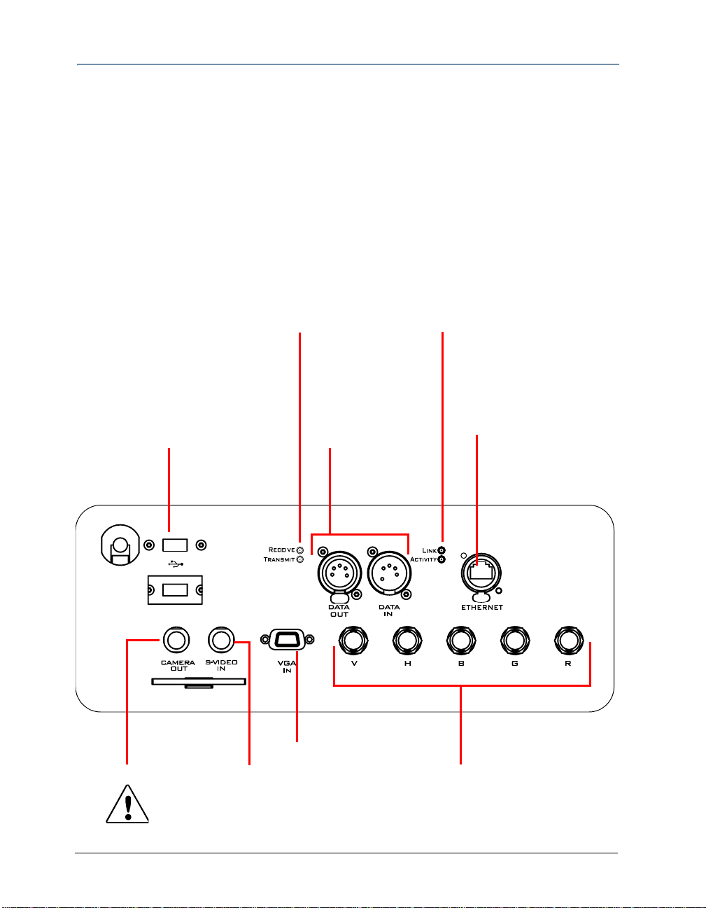
CHAPTER 2
Setup and Configuration
Hardware Components
Connection Ports
The DL.2 fixture’s back panel provides ports for:
• 5-pin DMX Data In and Data Out (see Setting up a Standard DMX Link on page 10 for
more information)
• Ethernet to connect to other DL.2 fixtures and your computer running the Content
Management Application (CMA) software on a fixture link (see Setting up an Ethernet
Fixture Link on page 11).
•Two USB ports for connecting peripheral drives to assist with troubleshooting
• RGBHV, VGA and S-Video In options for video input.
• Camera Out provides S-Video output from the internal camera to another DL.2 fixture or
other external video output device.
100-120 V;
50-60Hz; 7A
200-240 V;
50-60Hz; 3.5 A
S-Video Output
to another DL.2
fixture
Two USB ports
for peripherals
including hard drives
USB 1
USB 2
S-Video In
Receive LED
indicates DMX data
coming in
Transmit LED
indicates DMX data
going out
5-pin DMX512
Data In and
Data Out
VGA Input for
external source
Link LED indicates
hardware connection
via Ethernet
Activity LED indicates
CMA connection
Ethernet port to
connect DL.2 fixtures
to fixture link and
a computer
running the CMA
RGBHV input
for external
video source.
CAUTION:
To avoid damaging the fixture and voiding the warranty, do not
physically connect to the RGBHV and VGA inputs at the same time.
6 DL.2 Digital Light User Manual
Page 29
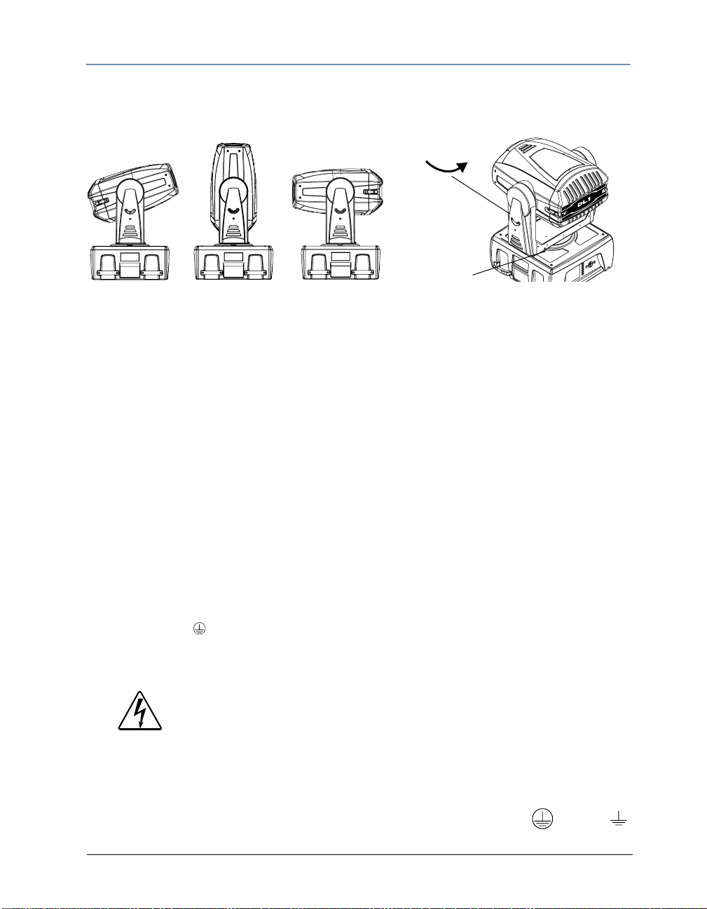
Setup and Configuration
]
[
CHAPTER 2
Pan and Tilt Locking
The DL.2 fixture ships with pan and tilt latches locked. You can unlock/adjust these latches to
stabilize the fixture for mounting.
]][
[[]
Tilt Lock
Pan Lock
Attaching a Power Cord Cap
The DL.2 fixture ships with an SJT power cord. Use the information in this section to replace the
power cord cap for locations with another electrical standard.
Because of the variety of power co rd caps used worldwide, High End Sys tems, Inc. can not make
specific recommendations for the power cord cap. Contact a local authority for the type of power
cord cap needed. When installing the power cord cap, note that the cores in the mains lead are
colored according to the following code:
• green and yellow = earth
• blue = neutral
• brown = live
Installing a Line Cord Cap - U.K. Only
In the United Kingdom, core colours in the mains lead of this equipment may not correspond
with the colored markings identifying the terminals in the fixture’s plug. In that case, install a
line cord cap in accordance with the following code:
• Connect the green and yellow core to the plug terminal marked with the letter “E,” or by the
earth symbol
or coloured green, or green and yellow.
• Connect the blue core to the terminal marked with the letter “N” or coloured black.
• Connect the brown core to the terminal marked with the letter “L” or coloured red.
WARNING:
Class 1 equipment - This equipment must be earthed.
Vatic Fitter Heads Information - Danmark
Advarsel: Beskyttelse mod elektrisk chock.
Vigtigt!
Lederne med gul/groen isolation maa kun tilsluttes en klem me maerket
DL.2 Digital Light User Manual 7
eller
Page 30
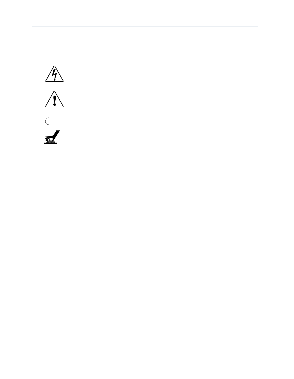
CHAPTER 2
Setup and Configuration
Mounting the Fixture
You can mount DL.2 fixtures suspended from a support system (such as a truss) or freestanding
on its base.
WARNING!
Equipment suitable for dry locations only. Do not expose this
equipment to rain or moisture.
CAUTION!
Always use a secondary safety cable when mounting this
fixture.
Maintain a minimum focus distance of 1.4 meters from a
1.4 m
combustible object.
Do not mount on a flammable surface.
Note: Due to the wide variety of possible lighting designs, High End
Systems cannot make specific mounting recommendations. Consider
the following procedure as a suggested guideline only.
Fog Machine Warning
Like all high quality video projection units, the DL.2 fixture must be kept protected from
excessive amounts of glycol fog, mineral oil, and smoke. DL.2 incorporates a two-stage air
filtering system with additional washable prefilters in the head and base housing to reduce
these risks to a minimum. However, you must follow these guidelines to ensure continued
operation of the fixture:
• Air filters (both fixture and projector) should be checked and cleaned on a regular basis.
When used in a closed or fixed environment where fog or haze is used, we recommend at
least a weekly check.
• Do not situate DL.2 in areas of high fog density such as directly in front of a fog machine or
mineral oil hazer.
• Minimize the exposure of DL.2 to both glycol fog and mineral oil.
DL.2 is a highly complex and sensitive electro-optical device and care and thought in how it is
used, rigged, and positioned will maximize the product’s life and your investment.
Note: Failure to follow these guidelines and carr y ou t regul ar ma in tenance
will void the warranty.
8 DL.2 Digital Light User Manual
Page 31

Setup and Configuration
CHAPTER 2
Mounting the Fixture Upright
CAUTION!
Do not mount the fixture upright without the four rubber feet
attached.
To mount the fixture upright, place the fixture on a sturdy, stable surface that will support more
than the
safety cables to secure the fixture to the surface.
53.5 kg (118 lb) weight of the DL.2 fixture. If the surface is above floor height, use
Truss Mounting
When mounting the fixture on a truss or another type of support:
• Verify the truss or support will handle the combined weight of all the devices on the truss.
• Always mount the DL.2 fixture with the mounting bracket assembly that shipped with your
fixture and a safety cable attached (using the mounting bracket) to the fixture’s base.
WARNING!
Before mounting, disconnect power to the fixture. If it has been
operating, allow the fixture to cool for five minutes before handling.
CAUTION!
Do not use C- Clamps to mount the DL.2 fixture to truss.
Use the following steps to mount a DL.2 fixture on a standard truss:
1. Due to it’s size and weight, at least two people should support the fixture while another
attaches clamps and safety cables. Always stand on a firm, stable surface when mounting a
fixture to its support.
2. Mount the clamps that shipped with fixture to the mounting brackets and then attach the
two mounting brackets to the base of the fixture using the provided quarter-turn screws.
Bracket screw holes
Safety
cable loop
DL.2 Digital Light User Manual 9
Page 32

CHAPTER 2
Setup and Configuration
3. Tighten the clamps firmly to the fixture’s base
and to the support.
4. Run the safety cable through the loop on the
fixture’s base, and around the truss.
Note: High End Systems does not recommend
operating the DL.2 fixture with the base
perpendicular to the stage floor (fixture
mounted sideways). Sideways
mounting will result in significantly
decreased lamp life.
Linking DL.2 Fixtures
DL.2 fixtures should be linked to a standard DMX512 link for control by a DMX desk as well as a
Ethernet fixture link for CMA functions.
Setting up a Standard DMX Link
The number of fixtures on a link will be determined by the combined number of channels
required by all the fixtures. The DMX channel range of a DL.2 fixture is determined by the
protocol mode you choose.
• DL.2 Standard Protocol = 170 channels
• DL.2 Dual Protocol = 132 channels
• Single Protocol = 94 channels
Use data-grade cable and 5-pin XLR cable connectors. For cable and connector specification, see
Cable and Connector Specifications on page 293.
T est each cable with a voltage/ohm meter (VOM) to verify correct polarity and to make sure that
the negative and positive pins are not grounded or shorted to the shield or to each other.
CAUTION!
Do not connect anything to the ground lug on the XLR connectors.
Do not connect or allow contact between the common (cable shield)
and the fixture’s chassis ground. Grounding the common could cause
a ground loop and/or erratic behavior.
To link one or more fixtures to a DMX controller:
1. Connect the male XLR connector of a DMX Data cable to the controller’s DMX Data Out
connector.
10 DL.2 Digital Light User Manual
Page 33

Setup and Configuration
[
[
[
[
CHAPTER 2
2. Connect the Data cable’s female XLR conn ector to the Data In connector of the first (or
next) fixture on the DMX link.
3. Continue linking the remaining fixtures connecting a cable from the Data Out connector of
each fixture to the Data In connector of the next fixture on the link.
4. Connect a male terminator to the Data Out connector of the last fixture in the link (see
Powering On the Fixture on page 12). For information on obtaining a terminator, see
Related Products and Optional Accessories on page 4. You can construct a terminator
according to the specifications listed in Cable and Connector Specifications on page 293.
Setting up an Ethernet Fixture Link
DL.2 fixtures utilize an Ethernet network to synchronize playback and access the CMA software
for remote content management and fixture configuration. If you are using a DMX console and
other automated lighting products compatible with Art-Net, this network can also serve as the
link for DMX control.
Linking Configurations
The following diagrams show configuration options for linking DL.2 fixtures to each other via
Ethernet for accessing the Content Management Application running on your computer and to
the DMX512 link for DMX desk control.
DMX Universe 1 DMX Universe 2
[[]]]][
Ethernet
[[]]]][
[[]]]][
DP2000
Hub
Laptop Computer
WholeHog 3 Console
DMX 512 Data Cabling
Ethernet Cabling
DL.2 Digital Light User Manual 11
Configuration Option 1
[[]]]][
Page 34

[
[
[
[
CHAPTER 2
Setup and Configuration
DMX Universe 1 DMX Universe 2
[[]]]][
Ethernet
Hub
[[]]]][
ArtNet
Laptop Computer
[[]]]][
[[]]]][
DP2000
WholeHog 3 Console
DMX 512 Data Cabling
Ethernet Cabling
Configuration Option 2
Powering On the Fixture
WARNING:
This equipment is designed for connection to a branch circuit
having a maximum overload protection of 20 A.
CAUTION:
Do not power on the fixture until verifying that the line cor d
cap is suitable for the power source in your location. For more
information, see
To power on the DL.2 fixture, simply connect it to an appropriately-rated power source.
Attaching a Power Cord Cap on page 7.
CAUTION:
Always isolate DL.2 media servers from generators with a UPS
or good quality power conditioner to prevent damage occurring
to the integrated media server and projector housed in the
DL.2 from generator drop-outs, and sharp voltage and
frequency fluctuations.
12 DL.2 Digital Light User Manual
Page 35

Setup and Configuration
CHAPTER 2
Homing the Fixture
When the DL.2 fixture is connected to an appropriately-rated power source, it automatically
begins a homing procedure to verify that the major functions of the fixture and its internal
projector are oriented properly.
Shortcut: Holding down the inner most (i.e. middle) two menu tab buttons for
more than two seconds will home the unit.
The DL.2 Menu Display Panel
The DL.2 display panel gives access to the fixture’s onboard menu system. Chapter 3: The DL.2
Menu System describes the menu system configuration options in detail.
Note: Most configuration features are also available through the Content Management
Application (CMA), (see
Viewing Fixture Configuration Values on page 205.)
DL.2 Digital Light User Manual 13
Page 36

CHAPTER 2
Setup and Configuration
Software Setup
Software setup for DL.2 fixtures requires the following steps:
1. After powering on the DL.2 media server, launch the CMA software
2. Check the software version installed and upgrade if necessary.
3. Configure the DL.2 fixture’s DMX source, DMX protocol, and DMX Start Channel.
Installing and Launching the Content Management Application (CMA)
The Content Management Application software that shipped on CD with your fixture
communicates remotely with Axon and DL2 medi a servers over an Ethernet network to:
• Upload and download custom digital content to fixtures
• Remotely control all menu commands
• Update software
Axon media servers can run the CMA directly. If you’re fixture network is linking DL.2 fixtures
only, you will need to run the CMA on a computer connected to the Ethernet link you have
established.
The following are recommended hardware requirements for a remote computer running the
CMA:
• Windows XP or Mac OS 10.4 or later
• Microsoft .Net Framework 1.1 with Service Pack 1 installed
• 100/1000 base Ethernet card (a Gigabit Ethernet card is recommended for fast content
uploading of large files)
After setting up an Ethernet network and linking all DL.2 f ixtures and your computer, insert the
CD that shipped with your fixture to automatically install the CMA on your harddrive.
For more information on CMA operation, see Chapter 16: Content Management Application
(CMA) on page 187.
Note: If the CMA doesn’t automatically launch, navigate to the CMA.msi file
in your windows browser and double click to launch.
When you launch the CMA, it automatically finds and identifies all DL.2 fixtures and Axon media
servers connected to the fixture link.
Note: To avoid problems with fixture communication over the Ethernet link,
disable all firewall programs on your computer when using the CMA.
14 DL.2 Digital Light User Manual
Page 37

Setup and Configuration
CHAPTER 2
Verifying and Upgrading Fixture and CMA Software
Fixture and CMA software are continuously being updated to increase performance and add new
features. The software loaded on you fixture may not be the most up to date. The latest fixture
and CMA software are always available at the High End Systems website.
CMA software version is noted upon installation and can be accessed after that under the File
menu.
The CMA All Servers view lets you view the fixture software version on all DL.2 and Axon media
servers linked to it via Ethernet.
You can also view the installed software versions
by navigating to the Info > Version screen of a
fixture’s menu system. The Software Version
DL.2
field displays software versions as:
(Major).(Minor).(Build).
For downloading and upgrading CMA or fixture
software, see Upgrading Software on page 202.
DL.2 Digital Light User Manual 15
Page 38

CHAPTER 2
Setup and Configuration
Configuring DL.2 Fixtures
Before programming the DL.2 fixtures from a DMX512 console, you need to:
• Identify the DMX Source for the fixture
• Select the Protocol type to determine the DMX channel range this fixture will utilize
• Select a Fixture Number to identify this fixture on the DL.2 fixture link (required if you will
be synchronizing output between fixtures).
• As sign a valid Start Channel (the first channel in the unique range of DMX channels
designated by the console for this fixture)
You can configure fixtures directly using the DL.2 menu system or remotely using the Content
Management Application.
Setup Configuration Using the Menu System
All setup parameters are located on the DL2
fixture’s menu DMX Screen.
information on using the DL.2 Menu System,
Chapter 3: The DL.2 Menu System on page
see
21.
DMX Source defines the source of DMX data
and has two options:
• DMX512—Data is transmitted over
standard DMX cables.
• Art-Net—Data is transmitted over
Ethernet cables using the Art-Net protocol.
Set the number of DMX Universes (and
DL.2 Ethernet Subnetworks containing this fixture from 0–16).
Choose from three DMX Protocol types:
• Standard protocol requires 170 channels and enables all DL.2 parameters for direct DMX
control.
• Dual protocol reduces the fixture footprint to 132 channels by implementing only two
graphic objects.
• Single protocol simplifies DL.2 control to a single graphic object and uses 94 channels.
Select a valid Start Channel in the Start Channel field by using the up and down arrows on the
multidirectional button to step through the numbers 1-512. For more information on choosing
valid DL.2 DMX Start Channels, see
For detailed
Determining a DMX Start Channel on page 38.
• Standard protocol valid start channel = 1–343.
• Dual protocol valid start channel = 1–381.
• Single protocol valid start channels = 1–419.
16 DL.2 Digital Light User Manual
Page 39

Setup and Configuration
CHAPTER 2
Setup Configuration Using the CMA
The Content Management Application running on your computer and linked to DL.2 fixtures via
Ethernet lets you remotely configure the DL.2 fixtures. For more information on the CMA, see
Chapter 16: Content Management Application (CMA) on page 187. To view configuration
information for a individual server, click on All Servers in the left pane of the CMA window and
select the + to view all the servers on the fixture network. Select a server in the left pane to
view its configuration information in the right pane.
To select a DMX Source type:
1. Scroll down the Configuration list in the right pane and
double click on the line with DMX Source in the Name
column to bring up the edit dialog box.
2. Choose between DMX512 and ArtNet as the source
from the drop down list in the option field.
To Select a DMX Protocol type:
1. Scroll down the Configuration list in the right pane and
double click on the line with DMX Protocol in the Name
column to bring up the edit dialog box.
2. Choose Standard, Dual, or Single from the drop
down list in the option field.
DL.2 Digital Light User Manual 17
Page 40

CHAPTER 2
Setup and Configuration
To edit the DMX Start Channel:
1. Scroll down the Configuration list in the right pane and
double click on the line with Start Channel in the Name
column to bring up the edit dialog box.
2. Enter a valid Start Channel for the protocol type you
have chosen.
Standard protocol = 1–343
Dual Protocol = 1–381
Single Protocol = 1–419
DMX Control Setup
Patching the DL.2 Fixture to a Wholehog Console
Wholehog console library systems patch the DL.2 fixture as three to five "fixture types". When
using Wholehog software; add one motion, one global, and three graphic "fixtures" for each
complete DL.2 unit in the Fixture Schedule or Add Fixtures window.
An easy way to organize these items is to assign user numbers e.g, (1-5 corresponds to DL.2
#1, where user number 1 is the motion, 2 is the global, and 3-5 the graphic fixture types).
Viewing Output
To output an image from a DL.2 fixture:
1. Open the dimmer on the motion fixture and assign the global intensity to full.
2. Assign an object's opacity to full.
When programming with Wholehog software, the Media Folder and Object parameters default to
1, so choosing any Media File value between 1 and 37 displays a media loop from the HES Core
folder (Media Folder 1) on a flat 4x3 rectangle (Object 1). The Dimmer, Global Intensity, and
Object Opacity parameters all need values greater than zero for an image to be visible.
If you have trouble viewing output and you are not using a lighting console from High End
Systems, check that the library for your desk has the correct default settings for all DMX
channels.
18 DL.2 Digital Light User Manual
Page 41
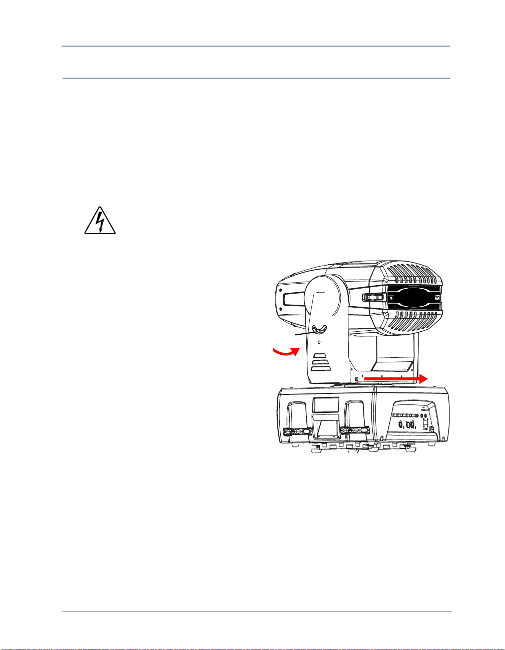
Setup and Configuration
CHAPTER 2
Shutting Down the Fixture
Recommended Shutdown Options
There are two recommended ways to shutdown the fixture:
1. A DMX controller can shut down the fixture’s motion controls and projector remotely with
the shutdown option of the control channel (see Fixture Operations on page 180).
2. The DL.2 fixture automatically shuts down in the event of DMX data loss. The default time is
10 min. To edit the length of time the fixture waits for a DMX input before shutting down,
use the CMA (see
(see Set_Fixture Screen on page 30).
Placing Fixture in Road Case
Before shipping the DL.2 fixture, lock its pan and tilt
position so the fixture does not move during transit.
To lock the fixture:
Editing Configuration Values on page 20 5), or th e fi xture ’s menu system,
WARNING:
Removing power directly without the shutdown sequence built
into the two recommended procedures can severely redu c e
fixture reliability.
1. Orient the projector head pan position as
shown for packing in the road case and secure
with the pan lock located on the yoke base.
Note: This is the only pan position that locks.
2. Move the tilt lock peg to the upper left (lock ed)
position.
3. Gently move the projector head and yoke to
verify that both pan and tilt positions are locked
in place.
DL.2 Digital Light User Manual 19
Tilt
Lock
Pan
Lock
Page 42

CHAPTER 2
Setup and Configuration
4. Place the DL.2
fixture in its
provided road
case for
shipping.
1. Place Top over the fixture first
2
. Bring sides of case together and latch.
20 DL.2 Digital Light User Manual
Page 43

Chapter 3:
The DL.2 Menu System
You can use the DL.2 fixture’s Menu System to configure the fixture,
review diagnostic feedback, and view content information.
The DL.2 fixture use a 5” LCD screen to display the onboard menu system. Navigation and select
buttons let you move to different tab levels and options displayed on the Menu scre en.
Note: You can also access most Menu options through the CMA (see Chapter 16:
Content Management Application (CMA) on page 187). Certain options can also be
controlled remotely via a DMX console’s Control channel (see Control Function
Options on page 180).
Menu Panel Components
System State
LEDs
*Escape
Multidirectional navigation button
Tab Select Buttons
*Enter
Menu Tabs
Menu Display
Adjustments
Display
LED
Active Screen displays the
currently selected screen
* Function will automatically reverse when fixture is inverted.
The LCD screen displays the menu arranged with a series of Menu Tabs along the left side for
accessing configuration screens and options on the currently active screen. Clicking on one of
the Tab Select buttons selects the tab to the right of it on the screen.
The large Multi-directional button controls movement between fields. The Escape button to
the left cancels a selection and the Enter button to the right selects and stores a selection.
DL.2 Digital Light User Manual 21
Page 44

CHAPTER 3
The DL.2 Menu System
Functionality for each of these three buttons automatically reverses when the fixture is rotated
to keep operation consistent. You can also manually set this option (see
page 30).
The fields in the Active Screen display current configuration settings and uses drop down
boxes, numeric up/down selectors, and other user interface options to select in editable fields.
Display Options on
LCD Display Adjustment Buttons
The four LCD Display Adjustment buttons next to
the LCD screen control and provide visual
for the menu display.
adjustments
LCD Display Power Button
The button nearest the green LED is the LCD display
power button. Holding it down for two seconds turns
the Menu display on or off. Use this in situations when
you need to turn the Menu display completely off
instead of dimming it to video black.
Menu
Menu Select
LCD Power
Display LED
If you turn the LCD off and then remove power to the
DL-2, the LCD power will restore the default (ON)
when you reapply power to the fixture.
Menu Display Adjustment Buttons
Note: The LCD screen power button doesn’t affect power to the fixture or
the internal projector
LCD Display Menu Options and Selection
The button furthest from the green LED is the menu button. Pressin g this brings up th e different
functions contained in the LCD screen itself. The screen menu options are:
• Picture adjusts the sharpness of the screen
• Color adjusts the rich ness of the color
• Contrast adjustment
• Black Level adjustment
• Tint adjustment
• Restore returns the screen to the factory defaults
The other two buttons are used to adjust the currently selected function.
Note: Display Black Level can also be controlled by the DL.2 menu system (see
Set Tab on page 30) or remotely through the configuration options in the
CMA (see Editing Configuration Values on page 205).
22 DL.2 Digital Light User Manual
Page 45
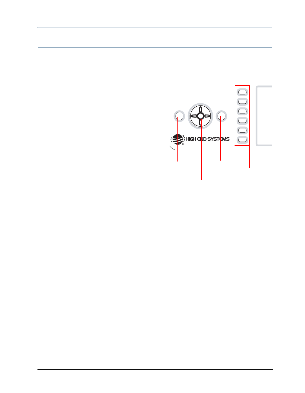
The DL.2 Menu System
CHAPTER 3
Navigating the Menu
Select any tab by pressing the co rresponding button to the side of the display. The tab label will
be bold when selected. Use the left and right arrow keys on the navigation buttons to move to a
different screen.
Press the Tab Select button corresponding to the
screen you want and press the <Enter>
select.
Use the multidirection button to move left/right/up/
down to a field. The currently selected field will be
highlighted.
Press the <Enter> button to go into edit mode the
selected field and a list box will open to show all the
options for that field.
Use the Up/Down keys to scroll through the items in
the list highlighting the current item. Pr essing the
<Enter> button again stores the selection and
closes the list.
button to
Escape
Enter
Navigation
buttons
Tab
Select
Buttons
T o edit a field, press the <Enter> button to pop-open the drop down list where up/down selects
the item. Pressing <Enter> again commits the change. Pressing the <Escape> button instead
of <Enter> leaves the original setting and closes the list.
To return to a hig h tab level, press the left direction on the Navigation button.
DL.2 Digital Light User Manual 23
Page 46

CHAPTER 3
The DL.2 Menu System
DL.2 Menu Options
The menu display consists of a set of top-level tabbed screens and their associated subtabs.
Main
Tab
DMX Control Source DMX512 Sets DMX as fixture communication source
Set Fixture Pan Invert On Inverts the direction of the pan motor.
Sub-Tabs/
Screens
Raw View Main Table Displays DMX values for all 512 DMX link channels
Protocol
View
Motion Displays fixture Movement and Camera parameter
Global Displays Intensity, Iris, Edge Fade, Viewpoint and
Obj 1 Displays Position, Rotation, Scaling, and Effects
Obj 2
Obj 3
Fields
Controls
Protocol Standard Motion + global + 3 objects = 170 channels
Fixture ID 1-255 Assigns the fixture a unique number on fixture
Start
Channel
Offset Scrolls through rows of DMX values
Refresh
Rate
Refresh
Timer
Tilt Invert On Inverts the direction of the Tilt motor.
Pan/Tilt
Swap
Data Loss
Timeout
Iris
Display On Default intensity
Display
Invert
Options Function/Notes
Art-Net Set Universe field from 0-16 [Art-Net protocol]
Set Subnet field from 0-16 [Art-Net protocol]
Dual Motion + global + 2 objects = 132 channels
Single Motion + global + 1 object = 94 channels
network
1-512 Sets the fixture’s DMX start channel
in rows of values.
0-44 Times/second for refreshing displayed values
On DMX values updated instantly
Off Display does not refresh
values
Keystone correction parameters values for the
composite image
parameters values for the selected graphic object
Off Default
Off Default
On Swaps Pan and Tilt directions
Off Default
Long Closes iris after a 5 minute DMX data loss
Short Closes iris after a 5 second DMX data loss
adjustment
Preview Displays current
content preview
Off Turns off display after a period of time
On Inverts menu display and navigation
Off Turns off the display invert
Auto Automatically inverts display >45°
Note: Unless you select Off,
you can adjust display
intensity level.
24 DL.2 Digital Light User Manual
Page 47

The DL.2 Menu System
CHAPTER 3
Main
Tab
Set Fixture External
File Displays content file locations and allows a content
Sub-Tabs/
Screens
Projector Factory
Fields
Controls
SVideo
Defaults
Projector
Input
Projector In
by DMX
Projector
Lamp
Projector
Startup
Mode
Projector
OSD Menu
Zoom
Override
Focus
Override
Projector Defaults Selecting button restores Factory Projector
Projector
Ceiling
Projector
Rear
Options Function/Notes
NTSC_M
NTSC_MJ
PAL_B
PAL_D
PAL_G
PAL_H
PAL_I
PAL_M
PAL_N
SECAM_B
SECAM_D
SECAM_G
SECAM_H
SECAM_K
SECAM_K
1
SECAM_L
SECAM_L
1
On Restores factory default settings
Off Default
External Chooses the input the Projector will accept
Internal
Yes Selecting Yes allows projecto r’s input source to be
No Disables changing projector input via DMX
On Manually turns Projector Lamp on
Off Manually turns Projector Lamp off
Always Turns the projector lamp on whenever the fixture is
Manual Turns on the projector lamp when Projector Lamp =
DMX Turns the projector lamp on with DMX
On Navigation buttons control Projector Menu System
Off Navigation buttons control Fixture Menu System
On On Overrides the DMX values sent by the console.
Off
On On Overrides the DMX values sent by the console.
Off
On Rotates the image 180 degrees
Off Default
On Inverts the image for projection from behind a
Off Settings do not match factory defaults
Identifies the SVideo format used for video input.
selected from DMX
connected to power
On
input (default)
Set value manually from 0-255
Set value manually from 0-255
Defaults
screen
preview
(see page 35).
DL.2 Digital Light User Manual 25
Page 48

CHAPTER 3
The DL.2 Menu System
Main
Tab
Info Temp Box Reset Displays fixture base housing’s current, minimum
Test Home Motion All Home Resets all mechanical functions to default positions
Reset Reboot Media Server Selecting Restart reboots the internal media server
Sub-Tabs/
Screens
Version Software Version Displays currently installed versions
Hours Lamp
Status Motion Shutdown Displays system activity and errors. For more
Self Test Self Test
Fields
Controls
Head Reset Displays current, minimum and maximum
Firmware Version
Windows XPe
Pan Encoder Version
Tilt Encoder Version
Unique ID Displays Internal ID
IP Address Displays fixture’s IP address
Fixture Name Displays a currently assigned Fixture Name
Hours
Fixture
Hours
Projector Status
Lamp Status
Projector Air Filter
Motion
Pan/Tilt
Motion Iris/
Zoom/
Focus
Pan/Tilt
Self Test
Iris
Self Test
Zoom
Self Test
Focus
Video
Test
Delete User Content Selecting Delete erases all User Content on server
Upgrade Factory
Content
Options Function/Notes
and maximum temperature. Pressing Reset reverts
all settings to the current temperature
temperature of fixture head. Pressing Reset reverts
all settings to the current fixture head temperature
Reset Monitors lamp, fixture, and filter hours of operation.
On Selecting On starts a test sequence for Pan and Tilt
Off
On Selecting On starts a test sequence for Iris
Off
On Selecting On starts a test sequence for Zoom
Off
On Selecting On starts a test sequence for Focus
Off
On Selecting a Video Pattern and On displays a
Off
Selecting Reset reverts hours to 0.
information, see
Troubleshooting.
Resets Pan and Tilt functions to default positions
Resets mechanical functions for Iris, Zoom, and
Focus to default positions
mechanical functionality
mechanical functionality
mechanical functionality
mechanical functionality
sample video to test graphics engine functionality.
Selecting Upgrade installs updates to factory
content (requires connection to the CMA)
Chapter 17: Maintenance and
26 DL.2 Digital Light User Manual
Page 49

The DL.2 Menu System
CHAPTER 3
Menu Screen Descriptions
Menu screens are presented on the display as a tabs. Sub-levels for a specific menu appear as
that tab as is selected.
DMX Tab
The DMX screen lets you configure the fixture
for the DMX link, view the DMX settings for the
fixture on each channel of its range, and view
all 512 channel values on the DMX link.
DMX_Control Screen
Use the Control Tab to configure your fixture.
You can choose from three DMX Protocol
types:
• Standard protocol requires 170 channels
and enables all DL.2 parameters for direct
DMX control.
• Dual protocol reduces the fixture footprint
to 132 channels by implementing only two
graphic objects.
• Single protocol simplifies DL.2 control to a
single graphic object and uses 94 channels.
DMX Source defines the source of DMX data
and has two options:
• DMX512—Data is transmitted over
standard DMX cables.
•
Art-Net
of DMX Universes (and DL.2 Ethernet Subnetworks containing this fixture from 0–16).
Scroll through the numbers 1-512 in the Start Channel field to set a valid start channel for the
protocol you have chosen:
• Standard protocol = 1–343
• Dual Protocol = 1–381
• Single Protocol = 1–419
For more on choosing valid DL.2 start channels, see
You can assign each fixture a unique Fixture ID number from 1-255. This allows the fixture to
be identified on the DL.2 ethernet fixture link for tasks like synchronizing playback between
DL.2 fixtures and uploading custom content with the Content Management Application (CMA).
You can manually set this number in the menu or through the CMA, see
page 190. For more on DL.2 Ethernet fixture links, see Setting up an Ethernet Fixture Link on
page 11.
DL.2 Digital Light User Manual 27
—Data is transmitted over Ethernet cables using the Art-Net protocol. Set the number
Determining a DMX Start Channel
Fixture Identification on
on page 38.
Page 50
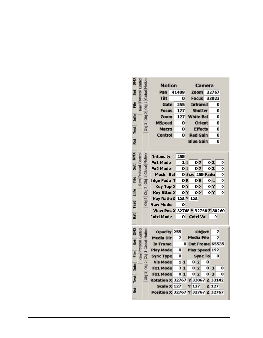
CHAPTER 3
The DL.2 Menu System
DMX_Protocol Tab
This tab displays the current DMX value being received from a console for each parameter after
any conversion, such as internal self test or protocol conversion. The DMX parameters are
grouped into general categories, each with a separate tab. For more information on individual
parameters and their DMX value ranges, see
229.
Appendix A: DL.2 and Axon DMX Protocol on page
DMX_Protocol_Motion Screen
The Motion tab displays parameters associated
with fixture movement, projector control and
integrated camera functionality.
For more information on specific Motion and
Camera parameters, see:
• Chapter 14: Fixture Motion Functions
• Chapter 15: Live Video Input and Control.
DMX_Protocol _Global Screen
The Global tab display the current values for
parameters that affect the composite image.
For more information on specific Global
parameters, see Chapter 11: Global Functions.
DMX_Protocol _Obj Screens
Obj 1, Obj 2, and Obj 3 tabs display
parameters values affecting a single object’s
content. For more information on specific
Graphic Function parameters, see:
• Chapter 7: Graphic Functions: Defining
Content;
• Chapter 8: Graphic Functions: Rotation,
Position, Scale;
• Chapter 8: Graphic Functions: Opacity and
Effects; and
• Chapter 10: Graphic Functions: Synchronizing Content.
28 DL.2 Digital Light User Manual
Page 51

DMX_Raw Screen
You can view the DMX values of all fixtures on
the link. The Raw T ab displays every
for Channels 001–512 in lines of eight DMX
values each per screen. The Offset number at
the beginning of each line indicates the first
DMX channel with a value displayed on that
line. Use the scroll bar at the left of the offset
number to scroll through all the values.
The Refresh Rate is the rate at which DMX is
being received by the fixture.
With Refresh Timer set to On, you see the raw
DMX values updated instantly.
DMX value
The DL.2 Menu System
CHAPTER 3
DL.2 Digital Light User Manual 29
Page 52

CHAPTER 3
The DL.2 Menu System
Set Tab
Set_Fixture Screen
The Fixture tab provides options for selecting or
changing fixture movement, dimming the
mechanical iris, and controlling the LCD display
black level and orientation.
Movement Options
Set the Pan Invert option On to invert the
direction of the pan motor. Use this option to
coordinate movements between fixtures facing
each other in a horizontal orientation. Off is the
default setting.
Set the Tilt Invert option On to invert the direction of the tilt motor. Use this option to
coordinate movements between fixtures facing each other in a vertical orientation. Off is the
default setting.
Setting Pan Tilt Swap option On swaps the pan and tilt motor operation to coordinate
movements between fixtures mounted perpendicular to each other. Off is the default setting.
Timeout Options
The Dimmer Iris closes when it stops receiving DMX data for a designated time interval. The
Data Loss Timeout Iris option sets the DMX data loss time interval as Long (5 minutes) or
Short (5 seconds). Short is the default setting.
After 10 minutes of no data, the fixture will shut down the projector and the motion functions.
Fans remain on to maintain the temperature control for the internal graphics engine.
Display Options
The Display field lets you adjust the black level of the Menu display with the following options:
• On is the factory default.
• Preview displays the most recent media change of any Graphic function, when opacity > 0.
The DL-2 Menu screen displays content in both partial and full screen. The Preview function
can be enabled from the DL-2 menu, the CMA, as well as remotely via DMX.
— When Preview is enabled, a partial, full color video is shown on the LC D display along with
the folder, file, and DMX information. If there is no change of content on any Graphic
Function it will automatically sw itch to full screen mode within 12 seconds.
— The Preview function always shows the late st selected conten t without any modificat ion of
effects. Preview mode displays movies and still images only. S-video and internal camera
input will not be displayed in the Preview mode.
— The Preview function uses substancial memory and should be turned off when rendering
all three Graphic Object options to ensure high quality playback.
30 DL.2 Digital Light User Manual
Page 53

The DL.2 Menu System
CHAPTER 3
Note: After selecting the On or Preview option, you can use the numeric up/down control
to adjust the Menu display brightness level from 25 (dim) to 100 (brightest).
• Off turns off the display after 20 seconds of inactivity. Touching any bu tton on the fixture
menu will re-enable the display.
The Display Invert field inverts the display and navigation control functions. This is useful in
certain fixture orientations. There are three invert control options:
• On manually inverts the display and navigation buttons
• Off manually turns off the display invert function
• Auto sets the display to invert automatically when the fixture is rotated more than 45% off
the horizontal axis. This is the default setting.
The Multiple SVideo Format field lets you designate which SVideo format the fixture will accept.
DL.2 fixtures support multiple SVideo formats including:
NTSC_M PAL_B PAL_H SECAM_B SECAM_K
NTSC_MJ PAL_D PAL_I SECAM_D SECAM_K1
PAL_G PAL_M SECAM_G SECAM_L
PAL_N SECAM_H SECAM_L1
Note: The format must be set to NTSC_M to receive input from the internal camera.
Restoring Factory Defaults
Selecting On in the Factory Defau lt s field restores all factory default fixture settings.
Set_Projector Screen
The projector tab provides settings related to
the internal projector functionality.
Use the Projector Input option to select
which input the projector should accept. When
External is selected, the projector takes input
directly from an external source and bypasses
the internal graphics engine. When Internal
is selected, the projector takes input directly
from the graphics engine. Internal is the
default configuration setting.
Setting the Projector In By DMX field to Yes
sets DMX as the projector’s input source.
The Projector Lamp field lets you manually turn the lamp On or Off.
Use the Projector Powerup to choose the control option for turning the lamp on. The options
are: ALWAYS ON, MANUAL, DMX. This only takes effect when the fixture powers up.
• Al way s On turns the projector lamp on when the fixture starts up regardless of whether
there is a DMX/Art-Net signal. If there is no DMX/Art-Ne t signal the lamp sh uts off when the
shutdown timeout period expires.
DL.2 Digital Light User Manual 31
Page 54

CHAPTER 3
The DL.2 Menu System
• Manual turns on the projector lamp only when set to On via DMX, Menu or the CMA.
• DMX only turns the lamp on when it receives a DMX signal or Art-Net signal connected
to it.
When the internal projector menu is selected for display, you may need to manually adjust the
zoom and /or focus parameters to view the display clearly. The Zoom Override and Focus
Override options override the DMX values sent by the console and allow you to control Zoom
and focus manually with a DMX decimal value between 0-255.
Projector Ceiling rotates the image 180 degrees so you can adjust for whether the fixture is
hung in the air or sitting on the floor.
Projector Rear projects a mirror invert of the image
rear-screen projection applications.
for
Projector Control Menu can be set to On to display
the projector’s menu system. In this state, the
directional front panel buttons (multi-directional switch
and the buttons on either side of it) control the
projector menu rather than the LCD menu.
T o rev ert back to the Menu display, press one of the six
side menu buttons. When the Projector Control Menu is
set to Off, the projector control menu is not displayed.
Turning Projector Defaults On will reset all the
options on the Projector tab to their factory default
settings. For more information, refer to the Projector
User Manual that shipped with your DL.2 fixture.
Projector Menu
Command
Default
LANGUAGE ENGLISH
CEILING OFF
REAR OFF
INPUT3 SVIDEO
SYSTEM AUTO
INPUT1 RGB
SCREEN NORMAL
INPUT2 RGB
POWER
OFF
MANAGEMENT
LOGO OFF
ON START OFF
FANSPEED NORMAL
File Screen
The File screen displays information about
the currently selected content file. Use this
screen to preview content — both still images
and movies.
When you select the File tab, the file plays in
the window to the left. The bottom right
window displays content folders and
highlights the current file location.
You can scroll through the Content folders
and the files inside each folder to preview any
content file.
32 DL.2 Digital Light User Manual
Page 55

The DL.2 Menu System
CHAPTER 3
Test Tab
Test_Home Screen
Homing sets a fixture to it’s default positioning. The fixture automatically home s
whenever it is connected to power.
You can manually home all or separate
mechanical functions using this menu tab.
• Motion All option on this manually homes
the entire fixture.
• Motion Pan/Tilt homes only pan and tilt
positions.
• Motion Iris/Zoom/Focus sets the Iris,
Zoom and Focus to default.
• Calibrate Motors realigns the Pan and Tilt stepper motors after maintenance procedures.
The DL.2 can also be remotely homed via a DMX controller, (see Control Function Options on
page 180) or through the Content Management Application, (see Editing Configuration Values
on page 205).
Test_Self Test Sc r een
You can check the mechanical functionality of
Pan/Tilt, Iris, Zoom, and Focus assemblies
on the fixture head. Select On to start the test
sequence.
The Video Test option opens the mechanical
iris and provides test patterns to check the
projection functionality. This lets you verify
that the graphics engine is operating without
having to use a DMX controller.
DL.2 Digital Light User Manual 33
Page 56

CHAPTER 3
The DL.2 Menu System
Info Tab
The Info tab displays current fixture information such as hardware and software versions,
sensor status, total fixture and lamp hours, DMX errors, and Status values. You can also reset
Lamp and Fixture hours.
Info_Hours
The Hours tab displays the Lamp and Fixture
hours of operation since the
Selecting the Reset button resets the
associated hours to zero. Lamp hours should
be reset to zero whenever a lamp is replaced.
Fixture Hours information is often used to
track fixture hours for a show or a rental
period. The number field displays the number
of hours the fixture has been operating since
the last reset. Pressing the Fixt ure Hours R eset
returns the value to 0.
Info_Version Screen
The Software Version field and Firmware
Version field display software versions as:
V(Major).(Minor).(Build)
A Fixture Name field displays a name for easy
reference in developing your show using the
Content Management Application.
last reset.
Info_Status Tab
This screen displays status errors and warnings
on items including:
•Temperature
• Filter life
•Lamp life
• USB and Camera Communication
• USB Security
For more detailed information, see Supported
Error/Warning Messages on page 220.
34 DL.2 Digital Light User Manual
Page 57

Reset Screen
The Reset screen provides options to reset,
shutdown and upgrade software.
Reboot Media Server restarts the fixture’s
internal graphics engine software.
Delete User Content removes all user content
on the selected fixture(s).
Upgrade Factory Content lets you reinstall
factory content in a recovery situation.
Note: A copy of the DL.2 Factory Content
can be obtained only from
High End Systems customer service.
The DL.2 Menu System
CHAPTER 3
DL.2 Digital Light User Manual 35
Page 58

CHAPTER 3
The DL.2 Menu System
36 DL.2 Digital Light User Manual
Page 59

Chapter 4:
DMX Programming Basics and Quick Start
If you are new to DMX programing, this chapter will give you a brief overview
on programming Axon and DL.2 media servers followed by a example of using
a Wholehog console to patch and display output from an Axon or DL.2 media
server.
DMX Programming Overview
DMX512 Links
A lighting console typically utilizes a protocol called DMX512 to communicate with automated
lighting fixtures and conventional dimmers. This protocol consists of 512 unique channels of
control per output link (universe). Typically a lighting fixture or device will use a channel for
each parameter’s function. Each channel consists of 256 values ranging from 0 to 255. The
lighting console is programmed to transmit a corresponding DMX value for the desired function
of each parameter. All DMX values are stored within in the lighting console, and typically are
referred to as cues, scenes, or presets. A lighting console locates a device on the link by it’s
DMX Start Channel.
8-bit vs. 16-bit DMX Parameters
Most parameters of an automated light use one channel of DMX providing 25 6 values of control
(0-255). This is known as 8-bit DMX. Although most DL.2 parameters use 8-bit DMX, several
require a more accurate range of values than can be provided with a single DMX channel.
By utilizing two DMX channels for a single parameter, 65535 values become available for
controlling and adjusting parameter functions. This is known as 16-bit DMX. You can adjust
16-bit DMX values in both coarse and fine increments. The first channel of the pair provides
coarse control changes of the DMX value in increments of 256. The second channel provides fine
control and changes of the DMX value in increments of 1.
Individual access of the two DMX channels used with 16-bit parameters varies by lighting
console. Most modern DMX consoles bind these two channels into a single 16-bit parameter to
accurately perform 16-bit crossfades. Consult your lighting console manual for further
information.
DL.2 Digital Light User Manual 37
Page 60

CHAPTER 4
DMX Programming Basics and Quick Start
Determining a DMX Start Channel
The DMX Start Channel is the first channel of a device’s channel range on a DMX link. There are
512 available channels on each DMX universe divided among all the devices in a particular
universe. A device must have a unique DMX Start Channel number in order to respond
independently to controller commands.
To determine each device’s DMX Start Channel, identify the footprint of every device on the
universe. The device’s footprint is the number of consecutive DMX channels a device requires
and is determined by the channels in the fixture’s protocol. The fixture’s DMX channel range
must not overlap any other device’s channel range on the link. When two devices on the same
DMX universe have overlapping channel ranges, one or both devices will be disabled or behave
erratically.
Axon media servers and DL.2 fixtures both
provide individual and composite graphical control
for up to three 3-D Objects. You can control the
“footprint” of the fixture on a DMX link by
choosing to implement only the number of 3-D
objects your application requires. Select the
protocol level in the fixture’s onboard menu
system for DL.2 fixtures or through the
either DL.2 fixtures or Axon media servers (see Viewing Fixture Configuration Values on page
205).
The tables that follow list the parameters included in each level of protocol for both the DL.2
fixture and the Axon media server.
CMA for
Protocol
Selection
Standard Protocol 149 170
Dual Protocol 111 132
Single Protocol 73 94
DMX Channel Range
Axon DL.2
38 DL.2 Digital Light User Manual
Page 61

DMX Programming Basics and Quick Start
CHAPTER 4
DL.2 Protocol Levels
Mechanical Control Global Control Graphic Object Control
Chan
#
1
2 24 Global Effect 1 Modifier 1 59 97 135 Media Folder
3
4 26 Global Effect 1 Modifier 3 61 99 137
5 Dimmer 27 Global Effect 2 62 100 138
6 Focus 28 Global Effect 2 Modifier 1 63 101 139
7 Zoom 29 Global Effect 2 Modifier 2 64 102 140
8 Mspeed 30 Global Effect 2 Modifier 3 65 103 141 Play mode
9 Macro 31 Mask Select (default iris) 66 104 142 Play speed
10 Control Function 32 Mask Size 67 105 143 Sync Mode
11
12 35 Edge Fade Right 70 108 146 Visual Mode Modifier 1
13
14 37 Edge Fade Left 72 110 148 Graphic Effect 1
15 Infrared 38 Keystone Top Left X 73 111 149 Effect 1 Modifier 1
16 Camera Sh utter 39 Keystone Top Left Y 74 112 150 Effect 1 Modifier 2
17 White balance 40 Keystone Top Right X 75 113 151 Effect 1 Modifier 3
18 Camera Or ientation 41 Keystone Top Right Y 76 114 152 Graphic Effect 2
19 Camera Effects 42 Keystone Bottom Right X 77 115 153 Effect 2 Modifier 1
20 Red Gain 43 Keystone Bottom Right Y 78 116 154 Effect 2 Modifier 2
21 Blue Gain 44 Keystone Bottom Left X 79 117 155 Effect 2 Modifier 3
21 Blue Gain 45 Keystone Bottom Left Y 80 118 156
Description
Motion 22 Global Intensity 57 95 133 Opacity
Pan
Tilt
Camera 33 Mask Edge 68 106 144 Sync To
Zoom
Focus
Chan
#
23 Global Effect 1 58 96 134 3-D Object File
25 Global Effect 1 Modifier 2 60 98 136 Media file
34 Edge Fade Top 69 107 145 Visual mode
36 Edge Fade Bottom 71 109 147 Visual Mode Modifier 2
46 X Ratio 81 119 157
47 Y Ratio 82 120 158
48 Viewpoint mode 83 121 159
49
50 85 123 161
51
52 87 125 163 Scale Y
53
54 89 127 165
55 Global Control 90 128 166
56 Global Control Modifier 91 129 167
Description Obj 1 Obj 2 Obj 3 Description
In frame
Out frame
X-axis rotation
Y -axis rotation
Viewpoint Position X
Viewpoint Position Y
VIewpoint Position Z
84 122 160
86 124 162 Scale X
88 126 164 Scale Z
92 130 168
93 131 169
94 132 170
Z-sxis rotation
X Position
Y Position
Z Position
DL.2 Digital Light User Manual 39
Page 62

CHAPTER 4
DMX Programming Basics and Quick Start
Axon Protocol Levels
Chan
#
1 Global Intensity 36 74 112 Opacity
2 Global Effect 1 37 75 113 3-D Object File
3 Global Effect 1 Modifier 1 38 76 114 Media Folder
4 Global Effect 1 Modifier 2 39 77 115 Media file
5 Global Effect 1 Modifier 3 40 78 116
6 Global Effect 2 41 79 117
7 Global Effect 2 Modifier 1 42 80 118
8 Global Effect 2 Modifier 2 43 81 119
9 Global Effect 2 Modifier 3 44 82 120 Play mode
10 Mask Select (default iris) 45 83 121 Play speed
11 Mask Size 46 84 122 Sync Mode
12 Mask Edge 47 85 123 Sync To
13 Edge Fade Top 48 86 124 Visual mode
14 Edge Fade Right 49 87 125 Visual Mode Modifier 1
15 Edge Fade Bottom 50 88 126 Visual Mode Modifier 2
16 Edge Fade Left 51 89 127 Effect Mode 1
17 Keystone Top Left X 52 90 128 Effect 1 Modifier 1
18 Keystone Top Left Y 53 91 129 Effect 1 Modifier 2
19 Keystone Top Right X 54 92 130 Effect 1 Modifier 3
20 Keystone Top Right Y 55 93 131 Effect Mode 2
21 Keystone Bottom Right X 56 94 132 Effect 2 Modifier 1
22 Keystone Bottom Right Y 57 95 133 Effect 2 Modifier 2
23 Keystone Bottom Left X 58 96 134 Effect 2 Modifier 3
24 Keystone Bottom Left Y 59 97 135
25 X Ratio 60 98 136
26 Y Ratio 61 99 137
27 Viewpoint mode 62 100 138
28
29 64 102 140
30
31 66 104 142 Scale Y
32
33 68 106 144
34 Global Control 69 107 145
35 Global Control Modifier 70 108 146
Description Obj 1 Obj 2 Obj 3 Description
In frame
Out frame
X-axis rotation
Y -axis rotation
Viewpoint Position X
Viewpoint Position Y
VIewpoint Position Z
63 101 139
65 103 141 Scale X
67 105 143 Scale Z
71 109 147
72 110 148
73 111 149
Z-sxis rotation
X Position
Y Position
Z Position
40 DL.2 Digital Light User Manual
Page 63

DMX Programming Basics and Quick Start
CHAPTER 4
Lighting Console Tips
Lighting consoles differ in many aspects and it is important to understand how your console
operates with Axon and DL.2 media servers.
Fixture Libraries:
Many sophisticated lighting consoles utilize pre-made fixture libraries. A fixture library consists
of profiles for various types of lighting fixtures and devices. Each profile corresponds to the
fixture’s DMX protocol and allows for ease of programming. Depending upon the manufacturer
of your lighting console, some parameters might have different labels for parameter names and
functions than are listed within this manual. Consult your lighting console manual for further
information.
Patching DL.2 Fixtures and Axon Media Servers
The DL.2 fixture consists of three different “fixture types” in the Wholehog 3 library systems.
This allows for ease of programming as well as the abil ity to adjust quickly for any of the v arious
DMX protocol options. The Motion fixture type controls the actual moving yoke, projector, and
integrated camera. The Global fixture type controls the global graphic engine functions such as
intensity, keystone correction, viewpoint, etc. The Graphic fixture type controls each graphic
object functions such as opacity, object, media, etc. The DL.2 protocol allows for 1, 2, or 3
graphic objects.
An Axon media server had no motion control but utilizes the same Global and Graphic fixture
types. In the Fixture Schedule or Add Fixtures window of Wholehog software, you would add 1
motion, 1 global, and 3 graphic “fixtures” for each complete DL.2 unit, or 1 global, and 3 graphic
“fixtures” for each complete Axon unit.
The best way to organize your patching is to assign user numbers for these items. Patch the
motion first, the global second, and the graphic fixture types last. For example, set up user
numbers 1-5 that correspond to DL.2 fixture number 1, where user number 1 is the motion, 2 is
the global, and 3-5 the graphic fixture types.
DMX Output Displays
Although all lighting consoles output the sa me 512 DMX channels per universe, the on-screen
labeling often differs. Parameter functions are displayed in either alpha-numeric descriptions
(strobe 1), percentage (0-100%) or decimal (0-255 for 8-bit and 0-65535 for 16-bit). Consult
your lighting console manual for further information.
DL.2 Digital Light User Manual 41
Page 64

CHAPTER 4
DMX Programming Basics and Quick Start
Wholehog III Programming Notes
Play Speed
You can adjust the Play Speed using the encoder wheel on the Beam parameter of the Graphic
fixture type. Additionally you can press “enable” and select “Media Speed Default On” to revert
to the default speed setting (DMX 128). Then if you touch the encoder again the previous play
speed will be recalled.
Mask Strobe
A unique function of the Wholehog 3 library system allows the creation of a special encoder
type. Flying Pig Systems has created a parameter called “mask strobe” in the Global fixture
type. When this is adjusted, it will automatically change the DMX value of the mask select
channel to the appropriate value and adjust the DMX channel for the strobe speed. This will
override the Mask Edge parameter as per the DL2 DMX Protocol.
Play Modes (Opacity)
Using the Graphic fixture type, press the Mode button to view th e play mode options. By default
all modes trigger normally. If available per the DL2 DMX protocol, you can select “Media T rigger
Opacity” to change to the Play Modes that trigger when Opacity is greater than zero. To restore
to normal triggering, select “Media Trigger Normal”.
CMY
The Global and Graphic fixture types both contain CMY controls for the Effect Mode modifier
channels. The default for Effect Mode 1 is set to CMY1 as well. For some effect options, the CMY
parameters will not adjust color, but will adjust the effect per the DL.2 DMX protocol. You can
find a description of CMY controls functionality for each effect option in
Options Descriptions on page 139.
Chapter 13: Effect Mode
Control Channel Functions
Many of the control channel functions in the motion “fixture” only operate if the dimmer
changes from >0 to 0 at the same time or just after a change is made to the control channel.
See the DL2 protocol for specific information.
42 DL.2 Digital Light User Manual
Page 65

DMX Programming Basics and Quick Start
CHAPTER 4
Quick Start Axon and DL.2 Control with a Wholehog Console
After Setting up and Configuring your media server (see Setup and Configuration on page 5),
use the following steps to get to the point of displaying output .
Step 1: In the Fixture Schedule or Add Fixtures window of Wholehog software, Add 1 motion, 1
global, and 3 graphic “fixtures” for each co mplete DL.2 unit , or 1 global, and 3 graphic “fixtures”
for each complete Axon unit.
Step 2: Assign user numbers for these items. Set up user numbers 1-5 that correspon d to DL.2
fixture number 1, where user number 1 is the motion, 2 is the global, and 3-5 the graphic
fixture types. Axon media servers will have user number 1-4 where user number one is global
and 2-4 the graphic fixture types. Patch the motion first, the global second, and the graphic
fixture types last.
DL.2 Digital Light User Manual 43
Page 66

CHAPTER 4
DMX Programming Basics and Quick Start
44 DL.2 Digital Light User Manual
Page 67

Chapter 5:
Tutorials
Five simple lessons get you started programming DL.2 and Axon media
servers with a Wholehog 3 or other DMX console.
The DL.2 fixture should be patched on your console as three to five fixture types. The MOTION
fixture type controls the actual moving yoke, projector, and Digital Eye camera. The GLOBAL
fixture type controls the global graphic engine functions such as intensity, keystone correction,
viewpoint, etc. The GRAPHIC fixture type controls each graphic object’s functions such as
opacity, object, media, etc. The DL.2 and Axon protocol allows for 1, 2, or 3 graphic
objects.Axon Media servers do not use the MOTION fixture type and require 1 GLOBAL and 1-3
GRAPHIC fixture types.
NOTE: The MOTION fixture Dimmer, GLOBAL fixture Intensity, and GRAPHIC fixture
Opacity parameters all have to be greater than zero before the image you create
becomes visible.
In the first three Lessons, the 3-D obj ect com ponent of the Gr aphic Objects is left at the defaul t
DMX value of 1 (flat plane). Note that all DMX v alues given in the examples are in decimal units.
If you have trouble producing the effects in these tutorials, and you are not working with a
Wholehog 3 console library, the default settings may be incorrect. All recommended default
values are listed in
“DL.2 and Axon DMX Protocol”.
Fixture Set-up (DL.2 Media Servers)
If you are using a DL.2 fixture, you will first need to set up the head and the projector. If you
are using the Axon Media Server, this will not be necessary and you can proceed to Lesson 1.
To set up the DL.2 fixture for the tutorials:
1. Select the DL.2's MOTION fixture, and set the Dimmer parameter to 100%
(DMX = 255). This will open the mechanical iris.
2. Set the GLOBAL fixture Intensity parameter and GRAPHIC OBJECT 1 fixture Opacity
parameter to 100% (DMX = 255).
3. Select the GRAPHIC OBJECT 1 and set the Media Folder to DMX = 39 (HES Setup and
Test). Dial the Media File to DMX = 5. This will bring up the convergence bitmap.
4. Select the DL.2's MOTION fixture and adjust Pan and Tilt prarameters until the fixture is
projecting to the desired location and adjust the Focus parameter until the convergence
bitmap becomes sharply focused.
5. Now you can remove or “knockout” the GRAPHIC OBJECT from the programmer and still
retain the MOTION and GLOBAL parameter settings.
6. Store these values somewhere on your console (to a palette or preset) so that this setup
can be quickly recalled whenever you need to adjust the Pan Tilt and Focus.
DL.2 Digital Light User Manual 45
Page 68

CHAPTER 5
Tutorials
Lesson 1: Cross Fading Between Graphic Objects
1. On your lighting console, set MOTION fixture Dimmer parameter (for DL.2 fixtures), the
GLOBAL fixture Intensity parameter, and GRAPHIC OBJECT 1 fixture Opacity parameter
to 100% (DMX value = 255).
Define Graphic Object 1
2. Set the Media Folder Parameter for the GRAPHIC
OBJECT 1 fixture to DMX value = 4. This selects
preloaded DL.2 media folder HES Atmospheric.
3. Set the Media File Parameter to DMX = 23. This
selects a water movie (23-Moonlite_Waves).
Add the DL.2 logo as Graphic Object 2
4. Select GRAPHIC OBJECT 2 fixture and change the
Opacity parameter to 100% (DMX = 255).
5. Set the Media Folder parameter to 1 and set the
Media File parameter to DMX = 01. This selects the
preloaded DL.2 logo as content.
Define Graphic Object 3
1. Select GRAPHIC OBJECT 3 fixture and set the Opacity
to DMX = 255 (100%).
2. Change the Media Folder parameter to DMX = 7
(A Luna Blue collection).
3. Change the Media File parameter to DMX = 2
(2-Blurs_Streaks_34).
Graphic Object 1
Graphic Object 2
Create Crossfade Cues
4. Select GRAPHIC OBJECT 2 and 3 fixtures and set the
Opacity parameter on both to DMX = 0. The only
content that is now showing is GRAPHIC OBJECT 1.
5. Record this look to your console as cue 1.
6. Set the of GRAPHIC OBJECT 3 Opacity parameter to
DMX = 255 (100%) and record this into your lighting
console as cue 2.
7. Now set the Opacity parameter of GRAPHIC OBJECT 3
to DMX = 0 and the Opacity of GRAPHIC OBJECT 2 to
DMX = 255 (100%). Record this as cue 3.
8. Now clear out all information in your console's programmer and play through the cues you
just recorded. You will see GRAPHIC OBJECT 1 crossfade to GRAPHIC OBJECT 3 and then
crossfade to GRAPHIC OBJECT 2.
46 DL.2 Digital Light User Manual
Graphic Object 3
Page 69

CHAPTER 5
Tutorials
Lesson 2 - Working with Multiple Graphic Objects
In this lesson, you will combine 2 Graphic Objects and use Chromakey Effect options to create
transparencies. You will be building off of cue 3 that was created in Lesson 1.
1. Be sure that the MOTION Dimmer parameter (for DL.2 fixtures), the GLOBAL Intensity
parameter, and GRAPHIC OBJECT 1 and 2 Opacity parameters are all set to 100%
(DMX = 255).
Apply Transparency Effects
2. With the GRAPHIC OBJECT 2 selected, open the Effect Mode 1 parameter.
3. Select the Chromakey Medium option(DMX = 27). The DL.2 logo "floats" on a water
background.
4. Select Invert Chroma Fine option (DMX value = 29). Now the Graphic Object 1 content
shows through the logo.
5. Record this look to your console.
DL.2 Digital Light User Manual 47
Page 70

CHAPTER 5
Tutorials
Lesson 3 - Girt, the Fire Breathing Lizard
In this lesson you will use Rotation, X, Y, and Z positioning, and scaling parameters to control
the interaction of multiple Graphic Objects. Bef ore you begin, clear any information out of your
programmer. Also, release playback of cues used in Lessons 1 and 2. You may want to start a
new cuelist for this exercise. If you are using a DL.2, be sure that you have set the fixture's
motion parameters up as described in the beginning of this tutorial.
1. Be sure that the MOTION Dimmer parameter (for DL.2 fixtures), the GLOBAL Intensity
parameter, and GRAPHIC OBJECT 1 Opacity parameter are all set to 100% (DMX = 255).
Define Graphic Object 1
2. Set the Media Folder parameter for GRAPHIC OBJECT
1 to DMX = 14 (HES Theme Stills).
3. Set the Media File parameter to a DMX value = 10.
(10-Tropical_10.jpg)
Define Graphic Object 2
The following steps select and position a flame graphic
object.
4. Select the GRAPHIC OBJECT 2 and set the Opacity parameter to DMX = 255 (100%).
5. Set the Media Folder parameter to DMX = 4 (HES Atmospheric).
6. Set the Media file parameter to DMX = 16 (16-Fire_Triple_Burst).
7. Set Effect Mode 1 parameter for GRAPHIC OB JECT 2 to DMX = 28 to select th e Chromakey
Coarse effect. This will make the black background transparent.
8. Reduce the Y Scale parameter to -5.7x (DMX = 55).
9. Reduce the X Scale parameter to -2x (DMX = 102).
10. Set the X Position parameter to a real world value of
37 pixels (DMX = 33530).
11. Set the Y Position parameter to a real world value of
13 pixels (DMX = 33042).
12. Set the Z Rotation parameter to a real world value of
-25° (DMX = 33042).
48 DL.2 Digital Light User Manual
Page 71

Define Graphic Object 3
The following steps create and position a puff of smoke.
13. Select the GRAPHIC OBJECT 3 and set the Opacity
parameter to DMX = 255 (100%).
14. Set the Media Folder parameter to DMX = 4 (HES
Atmospheric).
15. Set the Media File parameter to a DMX value of 17
(17-Dust_Explosion).
16. Set Effect Mode 1 parameter for GRAPHIC OBJECT 3
to DMX = 28 to select the Chromakey Coarse effect. This will make the black background
transparent.
17. Set the X Scale parameter to a real world value of -7.4x. (DMX = 33)
18. Set the Y Scale parameter to a real world value of -6.4x. (DMX = 46)
19. Set the X Position parameter to a value of 20 pixels. (DMX = 33177)
20. Set the Y Position parameter to a value of 8 pixels. (DMX = 33932)
21. Record this look into your lighting console.
CHAPTER 5
Tutorials
DL.2 Digital Light User Manual 49
Page 72

CHAPTER 5
Tutorials
Lesson 4: 3-D Objects, Rotation, Wobbulation, and Glow.
In this lesson you will learn how to put your chosen content on a 3D object and add rotation,
glow, and wobbulation.
1. Be sure that the MOTION Dimmer parameter (for DL.2 fixtures), the GLOBAL Intensity
parameter, and GRAPHIC OBJECT 1 Opacity parameter are all set to 100% (DMX = 255).
Define Graphic Object 1
2. With GRAPHIC OBJECT 1 selected, set the Media
Folder parameter to DMX
3. Set the Media File parameter to DMX = 3. This will
call up a black jpg.
4. Change the Object parameter to DMX = 23 (Outside
Cube).
5. Set the Effect Mode 1 to DMX = 73 (Glow)
6. Set the Effect 1 Modifier 1 parameter to 93%
(DMX = 236)
7. Set the Effect 1 Modifier 2 parameter to 25% (DMX = 63).
Note: Modifier channels for Effect Mode 1 are labeled as CMY in the Wholehog 3
system so you can also make use of the color picker, HSI, and other Wholehog 3
functions. Use the CMY parameter controls to adjust the three Effect Mode 1
Modifier parameters for both the Global and Graphic fixture types.
= 1 (HES Core).
8. Change the X Rotation parameter to 5°. (DMX = 32887)
9. Change the Y Rotation parameter to a real world value of -32°. (DMX = 32033)
Define Graphic Object 2
10. Select GRAPHIC OBJECT 2 and set the Opacity
parameter to DMX = 255 (100%).
11. Change the Media Folder parameter to DMX = 6 (Sean
Bridwell)
12. Change the Media File parameter to DMX = 16
(Fractal_Flower).
13. Change the Object parameter to DMX = 9 (moiré swirl)
14. Change the X Rotation parameter to 28°
(DMX = 33405)
15. Change the Y Rotation parameter to 36°
(DMX = 33577 )
16. Open the Effect Mode 1 parameter and set DMX = 66
(Circular Sinewave Z-axis Wobbulation) .
50 DL.2 Digital Light User Manual
Page 73

Adjust this effect with the Modifer parameters.
17. Set the Effect Mode 1 Modifier 1 parameter to
DMX = 104 (41%) to adjust wave size.
18. Set the Effect Mode 1 Modifier 2 parameter to
DMX = 86 (34%) to adjust wobbulation rate.
19. Set the Effect Mode 1 Modifier 3 parameter to
DMX = 114 (45%) to adjust offset.
NOTE: Modifier parameters make different
adjustments depending on the effect you
choose.
CHAPTER 5
Tutorials
DL.2 Digital Light User Manual 51
Page 74

CHAPTER 5
Tutorials
Lesson 5: Viewpoint
This lesson demonstrates the global parameters including viewpoint, and global effects.
1. Be sure that the MOTION Dimmer parameter, (for DL.2 fixtures) the GLOBAL Intensity
parameter, and GRAPHIC OBJECT 1 Opacity parameter are all set to 100%
(DMX = 255).
Define Graphic Object 1
2. With GRAPHIC OBJECT 1 selected, change the Media Folder parameter to feedback video
(DMX = 8).
3. Change the Media File parameter to DMX = 7 (7-SD_Cloud010)
4. Change the Object parameter to DMX = 21 (triangle)
5. Set the Z Position parameter to 118 pixels (DMX = 35187), the Y Position parameter to
30 pixels (DMX = 33372), and the X Position parameter to -43 pixels (DMX = 31888).
Define Graphic Object 2
6. Select GRAPHIC OBJECT 2 and bring the Intensity parameter to 100% (DMX =255).
7. Change the Media Folder parameter to DMX = 8 (feedback video).
8. Change the Media File parameter to DMX = 9 (9-SD_Deep01)
9. Change the Object parameter to DMX = 8 (toroid chk board)
10. Change the Z Position parameter to a value of 64 pixels (DMX = 34087)
Define Graphic Object 3
11. Select the GRAPHIC OBJECT 3 and change the Intensity parameter to 100% (DMX = 255).
12. Set the Media Folder parameter to DMX = 8 (feedback video)
13. Set the Media File parameter to DMX = 8 (8-S_Dash)
14. Change the Object parameter to DMX = 44 (star bevel 4)
15. Set the Z Position parameter to 40 pixels (DMX = 33592), the Y Position parameter to
-13 pixels (DMX = 32493), and the X Position parameter to 30 pixels (DMX = 33372).
52 DL.2 Digital Light User Manual
Page 75

Apply a Global Solarize Effect
16. Select your GLOBAL fixture and change the
Effect Mode 1 parameter to DMX = 10
(solarize 2) and observe how the global
effect changes all three of the graphic
objects at one time
17. Record this look into your console.
Adjust Global Viewpoint Mode
18. T o select the Perspective View with Spherical
Coordinates centered on Graphic Object 2,
set the Global Viewpoint Mode parameter
to sphr lyr 2 (DMX = 2).
19. Change the Viewpoint Position X
parameter to 316° and see how this
changes the viewpoint position of all three
graphic objects at one time.
CHAPTER 5
Tutorials
20. Change the value of the Viewpoint Mod e
parameter to ortho lyr 2 (DMX = 10) for an
Orthogonal View using Cartesian
Coordinates.
21. Set Viewpoint Position X parameter to
39° (DMX = 36337)
22. Set Viewpoint Position Y parameter to
101° (DMX = 41947)
23. Set Viewpoint Position Z parameter to
116° (DMX = 43354).
24. Record this into your console and play back
the cues you have created to observe how
viewpoint changes the perspective on the graphic
objects.
DL.2 Digital Light User Manual 53
Page 76

CHAPTER 5
Tutorials
54 DL.2 Digital Light User Manual
Page 77

Chapter 6:
Graphics Engine Overview
DL.2 fixture’s and Axon Media servers both use the same graphic engine
software to control content selection, playba ck, and 3-D Object and Global
manipulation.
Axon Protocol Options
Axon media servers and DL.2 fixtures both provide individual and composite graphical control
for up to three 3-D Objects. You can control the “footprint” of the fixture on a DMX link by
choosing to implement only the number of 3-D objects you need. Select the protocol level in the
fixture’s onboard menu system for DL.2 fixtures or through the CMA for both DL.2 fixtures and
Axon media servers (see
Appendix A: DL.2 and Axon DMX Protocol on page 229 has a detailed listing of all the
parameters for Axon media servers and they are discussed in more detail in the following
chapters.
Viewing Fixture Configuration Values on page 205).
Protocol Selection
Standard Protocol 149 170
Dual Protocol 111 132
Single Protocol 73 94
DMX Channel Range
Axon DL.2
Image Optimizing Controls
Images can now be optimized for each cue. It is no longer necessary to pre-optimize images
with a separate software system on a separate computer when preparing for a show. Using
Visual modes, (see
Contrast for each cue and for each image.
DL.2 Digital Light User Manual 55
Visual Mode Options on page 82), you can adjust both Black Level and
Page 78

CHAPTER 6
Graphics Engine Overview
Graphics Control Hierarchy
There is a hierarchy to the DMX control parameters. In general, object control parameters
render individual graphic images. Global control parameters act upon the composite image
created by combining multiple objects. Motion parameters control the fixture movement and
projection as well as live video feed from the internal camera.
It is especially important to keep this in mind when applying graphical effects. At the lowest
level, Graphic effects are applied to an individual 3-D Graphic Ob ject. Any Global effects appli ed
affect each object in the combined Object image. Finally, motion effects control the projection of
the composite image.
56 DL.2 Digital Light User Manual
Page 79

Graphics Engine Function Flow
Graphics Engine Overview
CHAPTER 6
A 3-D object
with a texture
is selected
Graphic
Functions
are applied
to each object.
Object
1
Content
Opacity
Playback
Visual Mode
Effect 1
Effect 2
Object
2
Content
Opacity
Playback
Visual Mode
Effect 1
Effect 2
Global
Effect 1
Global
Effect 2
Object
3
Content
Opacity
Playback
Visual Mode
Effect 1
Effect 2
Mask
Global Functions
are then applied to the
Edge Fade
composite-object image.
Keystone
Corre ction
Graphics Engine outputs
Global
Viewpoint
Global
Inten s ity
final image to projector
DL.2 Digital Light User Manual 57
Page 80

CHAPTER 6
Graphics Engine Overview
Graphics Engine Functions
Object Graphic Functions
For an individual object, you can control:
• The media file and 3-D object selection for the layer
• Media playback including
— What portion of the movie plays
— Playback speed
— Playback mode (direction and style of playback)
• The object transparency (opacity)
• Visual Effects including colormixing and geometric effects
• Synchronization
• Image Rotation, Scale and Position
Global Functions
Global controls are applied to composite image created by multiple 3-D images. For the
combined image, you can:
• Adjust the composite image intensity level
• Apply visual effects including colormixing and geometric effects
• Select a mask shape, size it and apply edge fades and color to the mask
• Apply and color mix an image edge fade
• Control keystone correction
• Establish the point in 3-D space f rom which image will be viewed
Making Graphics Effect Choices
Because you have control of many parameters, there are sometimes several ways to accomplish
the same look. For Example, to make an object appear larger, you can scale it along the x, y
and z axis, or you can apply a global control to zoom in on the z axis from a viewpoint that
makes the object seem to increase in size.
Which solution you choose depends, to a large extent, on the transition to other effects you
want to achieve.
58 DL.2 Digital Light User Manual
Page 81

Chapter 7:
Graphic Functions: Defining Content
Each Graphic Object’s content is composed of a 3-D object overlaid with a
media file. This chapter outlines how to select an image’s object and
media file components as well as define the video segment and its
playback.
Selecting Content
How Content is Organized
Every Axon and DL.2 media server has a file system that holds the
movies, images, and 3-D
server uses. These files, folders, and their associated DMX values
are collectively known as the “Content” on the media server.
The Content Management Application (CMA) organizes and identifies
content by source (preloaded Stock content or custom User content)
and type (Media files or 3-D Object files).
using the CMA to view and manage content, see
Management Application (CMA) on page 187.
objects that make up the content that the
For more information on
Content
Windows OS
Selecting Content
Three Parameters control Content selection. To define an image you have to set DMX values
greater than 0 for the 3-D Object, Media Folder, and Media File parameters. The selected media
file will be mapped onto the selected 3-D object.
Axon media servers
To output an image from a media server
1. Open the mechanical iris on the projector by setting it’s Dimmer parameter to full (100%).
2. Set the Global Intensity parameter to full (100%).
3. Set the Object opacity to full (100%)
4. Adjust the Object, Media Folder, and Media File parameters to greater than zero
When programming with Wholehog software, the Media Folder and Object par ameters default to
1 so choosing any Media File DMX value from 1-35 will display a media loop from the HES Core
folder (Media Folder 1) wrapped on a Flat Plane (Object 1).
Remember: The Dimmer, Opacity and Global Intensity Parameters all have to be
greater than zero before the image you create becomes visible.
DL.2 Digital Light User Manual 59
Page 82

CHAPTER 7
Graphic Functions: Defining Content
Content Selection Parameters
The following sections outline parameters you will use to create an image from content and
define it’s playback. You will set the parameters described in this chapter for each individual
Graphic Object you define.
Note: The suggested default DMX values given for each parameter are recommended
to build libraries that provide the easiest and most reliable content selection,
rendering and output. They are the default values built into the Wholehog
libraries for High End Systems consoles.
Object
The Object par ameter selects the 3-dimensional obj ect component of an image. Object files are
the 3-D object shapes used to build a total image. The graphics engine supports a combined
total of 255 stock and user-created object files.
Stock Objects have a fixed DMX value and cannot be edited. DMX values 1-149 are reserved for
identifying stock object files. User created object files must be assigned a unique DMX value
from 150-255.
For a reference of 3-D object files available as stock content with your media server and
information on how to create your own object files, go to the link for the Stock Object Guide for
the Axon or DL.2 products on
Default DMX Value: 1 = full screen flat surface
TIP: You can select the same object file for images that will be interacting with
each other. If both objects occupy exactly the same area in 3-D space,
“Z-fighting” (a shimmering ef fect ) on so me port ions of the comp osite i mage
can occur as the graphics engine tries to determine which object should be
in the foreground.
http://www.highend.com/support/digital_lighting/.
You can avoid this effect by making a slight adjustment to one of the
object’s scale or moving it forward or back (using the Z Position parameter)
in respect to the other.
60 DL.2 Digital Light User Manual
Page 83

Graphic Functions: Defining Content
CHAPTER 7
Media Folder
This parameter defines a folder (directory) containing a collect ion of media fil es. The media fi les
within the assigned folder can then be selected using the Media File parameter. Media Fol der
DMX values are assigned as follows:
• DMX values from 1-38 select from the stock Media collections that shipped with your media
server.
• A DMX value of 39 is reserved for a Setup and Test folder.
• DMX Values 40–239 are reserved for assignment to Custom folders containing user Media
collections
• A DMX value of 255 selects the live video feed from a DL.2 integrated video camera capture
or S-Video input.
Default DMX Value:
Media Folder Descriptions
DMX
Value
10 HES_Foliage Collection of abstract and realistic foliage and floral video loops
11 HES_Religious Religious themed video loops
12 HES_Gothic Set of themed video loops
13 HES_Digital_Aerials _2
14 HES_Theme_Stills Nature stills (foliage and flowers)
15 Apollo Glass 1 Digital Gobo Patterns, promotional
16 Artbeats Digital video loops, promotional
17 DHA_TopMac Digital patterns, promotional
18 Beacon DigiGobos Digital video loops, promotional
19 Amorphous Digi-gobos Digital animations, promotional
20 InLight Digital video loops, promotional
21 HES_Lithopatterns_1 High End Systems Lithopattern® images
22 HES_Lithopatterns_2 More images from High End Systems Lithopattern library
23 HES_Logos High End Systems® Axon and DL.2™ logos
24 HES_Hi_Res Variety of high resolution video backgrounds
DL.2 Digital Light User Manual 61
Media Folder Name Content Description
1 HES Core Media Files Premier High End Systems video loop collection
2 HES_Digital_Aerials_1 Digital still images and animations, designed specifically for aerial effects
3 HES_Oils Digitally simulated psychedelic oil projection loops
4 HES_Atmospheric Video loops of natural settings clouds, water, fire
5 On_The_Wall_Studios Digital video loops, promotional
6 Sean_Bridwell Digital video loops, promotional
7 A_Luna_Blue Digital video loops, promotional
8 Feedback_Video Digital video loops, promotional
9 HES_Textures Video loop textures
= 1 (HES Core Media files)
Digital still images and animations, designed specifically for aerial effects
Page 84

CHAPTER 7
Graphic Functions: Defining Content
DMX
Value
25 NASA_Images Space images from the Hubble telescope
26 Blue_Pony Assorted video loops
27 Diagnostics Setup and Test images
28-39 Reserved Reserved for HES use
40-240 Open Available for User Content
255 Video Input Live video input from internal camera or external device
Media Folder Name Content Description
Media File
The Media File parameter lets you identify which Stock or User media file to apply (map) as a
texture on the selected 3-D object. You can supplement the large library of Stock video loops
and still images with Custom files. This parameter selects media files from within the folder
defined by the Media Folder parameter.
For a reference of media files available as stock content with your media server, go to the link
for the Stock Content Guide for Axon or DL.2 products on
support/digital_lighting/. You can also view thumbnail images of media files in the CMA,
Viewing Files on page 193.
(see
Default DMX Value: 0 = No file selected
Tip: You can preview a visual display of the media files loaded on a media
server in the Content Management Application’s thumbnails view,
(see
Viewing Content on page 193) or in the File Tab of a DL.2 fixture
menu display.
http://www.highend.com/
62 DL.2 Digital Light User Manual
Page 85

Graphic Functions: Defining Content
CHAPTER 7
Defining a Media File Segment
You can define any portion of a video media file to play using the In Frame and Out Frame
parameters. By default, the In Frame is the beginning of the media file and the Out Frame is the
end of the file. Media files can have different lengths.
In Frame and Out Frame Parameters
You can select any segment of a media file for playback by assigning an In Frame value as a
start point and an Out Frame as an end point.
Note: DMX parameter values for these parameters do no t correspond to a
particular “frame”. They are defined as a percentage of the movie length.
This makes it possible to create segments with an Out Frame preceding
the In Frame and simplifies playback synchronization between media files.
The In Frame parameter corresponds to a 16-bit DMX value equal to a starting point for the
playback segment of the selected file. The Out Frame parameter corresponds to a 16-bit DMX
value equal to an end point for the playback segment of the selected media file.
Assigning the In Frame and Out Frame parameters to default DMX values will playback the
entire movie file. Choosing other settings are useful when you want to:
• begin or en d a media file at any point other than the default
• start or stop on a specific image
• you need to shorten the media file to a specific length
In Frame Default DMX Value:
Out Frame Default DMX Value: 65535 = The end of a media file is the playback endpoint.
As you move from 0 to 100% of the In Frame value range, you can select the beginning of a
media file segment as a percentage of the file length. Moving from 0 to 100% of the Out Fr ame
value range selects the end of a media file segment as a percentage of the file length.
Segment Selection Examples
You can create a segment anywhere between
the beginning and the end of a media file.
The In Frame does not have to precede the
Out Frame.
To skip a segment in the center of a media
file, set the In Frame to a point following the
Out Frame. The file will play from the In
Frame to the end and then start at the beginning of the file and play to the Out Frame.
When you create a segment in this way, you
may notice a jump as playback skips from the
end of the file to the beginning.
DL.2 Digital Light User Manual 63
0 = The beginning of a media file is the playback start point.
Example 1
Out Frame
75%
File
End
File
Start
In Frame
25%
Example 2
In Frame
75%
File
End
File
Start
Out Frame
25%
Page 86

CHAPTER 7
Graphic Functions: Defining Content
Defining Playback
After selecting and defining a media file segment to display on a 3-D object, you can choose
from several Playback Modes and assign a Playback Speed.
Playback Mode
A Playback Mode parameter for each 3-D image allows several playback options.
Default DMX Value: 0 = Plays forward in a continuous loop
DMX
Value
0 Play forward looping
1 Play forward once
2 Pause Stops playback at the frame currently playing
3 Play forward once if opacity > 0
4 Play forward if opacity > 0
5 Pause and rewind
6 Scrub In Frame Displays frame that has been defined by the In Frame parameter
7 Scrub Out Frame
8 Scrub In Frame with statistics
9 Scrub Out Frame with statistics
Scrubbing displays the selected frame of the composite output of the media server. While
scrubbing the In Frame, the frame selected by the In
displayed. Likewise, scrubbing the Out
coarse and fine channels. When the “with statistics” option is selected, the composite output
includes text data related to the selected frame. Remember that the In Frame and Out Frame
parameters are defined as a DMX value mapped to the percentage of the media file length, not
a specific frame.
Playback Mode Description
Plays the media segment from In Frame setting to Out Frame
setting, looping continuously
Plays the media segment from In Frame setting to Out Frame
setting, and holds on the last frame
Plays the media segment from In Frame setting to Out Frame
setting, and holds on the last frame, Plays only when the content
opacity value is greater than zero.
Plays media segment from In Frame setting to Out Frame setting,
looping continuously. Plays only when the content opacity value is
greater than zero.
Stops playback at the frame currently playing, then jumps to the In
Frame setting.
Displays frame that has been defined by the Out Frame
parameter
Displays frame that has been defined by the In Frame parameter
with media file data overlaid on the output.
Displays frame that has been defined by the Out Frame
parameter with media file data overlaid on the output.
Frame coarse and fine channels will be
Frame will display the frame selected by the Out Frame
Note: If the Global Control Mode parameter = 255, a DMX value of 1-3 for the
Global Control parameter provides an alternate font color to enhance
statistics readability.
64 DL.2 Digital Light User Manual
Page 87

Graphic Functions: Defining Content
CHAPTER 7
Playback Speed
The Playback Speed parameter controls the speed of the selected media file’s Playback Mode.
The Playback Speed for a media file is used whenever the Playback Mode Parameter’s DMX value
is assigned to any Play Forward option.
Default DMX Value: 128 = Playback at normal speed.
A DMX value of 0 or 128 (50%) plays back media files at the original recorded speed. DMX
values from 1 to 127 plays the media file back at an increasing speed, from slowest to the
original recorded speed. Values from 129-255 set playback speed from faster than normal to
fastest speed.
DL.2 Digital Light User Manual 65
Page 88

CHAPTER 7
Graphic Functions: Defining Content
66 DL.2 Digital Light User Manual
Page 89

Chapter 8:
Graphic Functions: Rotation, Position, Scale
You can independently control each Graphic Object’s rotation direction and
speed; along with it’s position and scale in x, y, and z axis directions.
The parameters described in this chapter are set for each Graphic Object you define.
Parameters for composite image rotation, position and global scale are described in
Chapter 11: Global Functions.
Note: The suggested default DMX values given for each parameter are
recommended to build libraries that provide the easiest and most
reliable content selection, rendering and output.
Rotating a 3-D Object
The Rotation parameters for each object control 3-D object rotation with 16-bit precisio n.
You can rotate a 3-D object up to 720° in either a clockwise or counterclockwise direction
around the X, Y and/or Z axis.
Note: Remember that rotation changes could affect an object’s
relationship to other objects.
When you rotate an object, you are rotating it around the selected axis. X Rotation produces
the effect of a top-to-bottom flip. Y Rotation produces a left-to-right flip. Z Rotation causes
a circular motion.
X Rotation
Rotates image
about the x axis
DL.2 Digital Light User Manual 67
Y Rotation
Rotates image
about the y axis
Z Rotation
Rotates image
about the z axis
Page 90

CHAPTER 8
Graphic Functions: Rotation, Position, Scale
The Rotation parameters’ suggested default values are the midpoint of the 16-bit DMX value
range, which is equal to no rotation. Increasing the DMX value from the midpoint indexes the
object in a clockwise direction. Reducing the DMX value below the midpoint indexes the object
in a counterclockwise direction.
When the DMX value for a rotation parameter is greater than the 720° limit in either direction,
the object begins rotating continuously. Additional adjustment to the DMX values increases the
speed of continuous rotation.
Counter-clockwise Clockwise
o
Indexed Rotation
oo
720-0 0-720
Indexed Rotation
0
Continuous RotationContinuous Rotation
0% 100%
Rotation Speed
25% 50% 75%
Rotation Speed
68 DL.2 Digital Light User Manual
Page 91

Graphic Functions: Rotation, Position, Scale
CHAPTER 8
Rotation Parameters
X Rotation
The X Rotation parameter rotates the selected Graphic Object around the x axis with 16-bit
precision. You can index the rotation or set a continuous rotation creating a vertical flip at
variable speeds.
This parameter lets you view an object from a di fferent angle by turning the object. Y ou can also
view an object from a different angle by changing the viewpoint in space for the composite
image, (see
Default DMX Value: 32768 (50%) = No X Rotation
% of
Value
Range
1–24 Continuous variable-speed counterclockwise image rotation around X-axis (fast to slow)
25 Continuous rotation stop
26–49 Rotates the image counterclockwise around X-axis in steps to –720 degrees
50 0° rotation around X-axis
51–74 Rotates the image clockwise around X-axis in steps to 720 degrees absolute
75 Continuous rotation stop
76–100 Continuous variable-speed clockwise image rotation around X-axis (slow to fast)
Global Viewpoint Mode on page 120).
Function
Tip: Using this parameter you can turn one object through another.
Original Object 1 and Object 2
DL.2 Digital Light User Manual 69
X-axis Rotation Applied to Object 2
Page 92

CHAPTER 8
Graphic Functions: Rotation, Position, Scale
Y Rotation
The Y Rotation parameter rotates or indexes the selected Graphic Object around the Y axis
with 16-bit precision. You can index the rotation or set a continuous rotation creating a
horizontal flip at variable speeds.
This parameter lets you view an object from a different angle by turning the object. You can also
view an object from a different angle by changing the viewpoint in space for the composite
image, (see
Default DMX Value: 32768 (50%)= No Y Rotation
% of
Value
Range
1–24 Continuous variable-speed counterclockwise image rotation around Y-axis (fast to slow)
25 Continuous rotation stop
26–49 Rotates the image counterclockwise around Y-axis in steps to –720 degrees
50 0° rotation around Y-axis
51–74 Rotates the image clockwise around Y-axis in steps to 720 degrees absolute
75 Continuous rotation stop
76–100 Continuous variable-speed clockwise image rotation around Y-axis (slow to fast)
Tip: Using this parameter you can turn one object through another
Global Viewpoint Mode on page 120).
Function
Original Object 1 and Object 2
70 DL.2 Digital Light User Manual
Y-axis rotation applied to Object 2
Page 93

Graphic Functions: Rotation, Position, Scale
CHAPTER 8
Z Rotation
The Z Rotation parameter rotates or indexes the selected Graphic Object around the Z axis
with 16-bit precision. You can index the rotation or set a continuous rotation creating a circular
spin at variable speeds.
Default DMX Value: 32768 (50%)= No Z Rotation
% of
Value
Range
1–24
25 Continuous rotation stop
26–49 Rotates the image counterclockwise around Z-axis in steps to –720 degrees
50 0° rotation around Z-axis
51–74 Rotates the image clockwise around Z-axis in steps to +720 degrees
75 Continuous rotation stop
76–100 Continuous variable-speed clockwise image rotation around Z-axis (slow to fast)
This parameter lets you view an object from a di fferent angle by turning the object. Y ou can also
view an object from a different angle by changing the viewpoint in space for the composite
image, (see
Tip: Using this parameter you can turn one object around another
Continuous variable-speed counterclockwise image rotation around Z-axis
(fast to slow)
Global Viewpoint Mode on page 120).
Function
Original Object 1 and Object 2
DL.2 Digital Light User Manual 71
Z-axis Rotation Applied to Object 2
Page 94

CHAPTER 8
Graphic Functions: Rotation, Position, Scale
Scaling the Object
You can scale an Graphic Object along the X, Y and/or Z axis to adjust the object size.
The Scale parameter adjusts the size of the object’s image up to approximately 10x its original
size. At a DMX value of zero, the image shrinks to a dot. At the midpoint of the DMX value
range, the image is normal size. When the DMX value is increased from the midpoint, the image
is enlarged. In addition, when the DMX value is reduced below the midpoint, an inverted image
is enlarged.
Use the X,Y and Z Scale parameters together to enlarge or shrink a 3-D object proportionally.
X Scale
The X Scale parameter scales the selected 3-D object along the x axis, either expanding it or
making it smaller. Use it when you want to size the object’s horizontal component.
A DMX value of 128 (50%) sets the object at its normal size. Values less than 50% shrink the
object horizontally to the smallest at 0. Values greater then 50% enlarge the object horizontally
to the largest at 255 (100%).
Default DMX Value: 128 (50%) = Normal Scale
Original Object 1 and Object 2
All Scale DMX values = 128 (50%)
72 DL.2 Digital Light User Manual
Object 2 X-Scale DMX value = 165
Scaled 3 times in X direction
Page 95

Graphic Functions: Rotation, Position, Scale
CHAPTER 8
Y Scale
The Y Scale parameter scales the selected 3-D object along the y axis, either expanding it or
making it smaller. Use it when you want to size the object’s vertical component.
A DMX value of 128 (50%) sets the object at its normal size. Values less than 50% shrink the
object vertically to the smallest at 0. Values greater then 50% enlarge the object vertically to
the largest at 255 (100%).
Default DMX Value: 128 (50%) = Normal Scale
Original Object 1 and Object 2
All Scale parameters DMX values = 128 (50%)
Object 2 Y-Scale parameter DMX value = 165
Scaled 3 times in Y direction
DL.2 Digital Light User Manual 73
Page 96

CHAPTER 8
Graphic Functions: Rotation, Position, Scale
Z Scale
The Z Scale parameter scales the selected 3-D object along the z axis, either expanding or
shrinking it. Use it when you want to size the object’s thickness.
A DMX value of 128 (50%) sets the object at its normal size. Values less than 50% shrink the
the object thickness until it reaches a point at a value of 0. Values greater then 50% enlarge the
object to a maximum thickness at 255 (100%).
Default DMX Value: 128 (50%) = Normal Scale
Original Object 1 and Object 2
All Scale parameters DMX values = 128 (50%)
Object 2 Z-Scale parameter DMX value = 223
Scaled 7.5 times in Z direction
74 DL.2 Digital Light User Manual
Page 97

Graphic Functions: Rotation, Position, Scale
CHAPTER 8
Changing Object Position
You can reposition each 3-D object’s position in 3-D space by moving it along the X, Y and Z
axes. The following parameters act on an individual object. Use these parameters to position 3D images in relation to each other.
X Position
The X Position parameter moves your object along the x axis with 16-bit precision.
The midpoint of the 16-bit DMX value range centers the image on the X-axis. Values below the
DMX midpoint move the object left, and values above the DMX midpoint move the object right.
Default DMX Value: 32768 (50%) = object centered in frame
Original Object 1 and Object 2
Object 1: X Position DMX value = 32022
All Position DMX values = 32768 (50%)
Object 1: X Position DMX value = 33561
Y Position
The Y Position parameter moves your object along the y axis with 16-bit precision.
DL.2 Digital Light User Manual 75
Page 98

CHAPTER 8
Graphic Functions: Rotation, Position, Scale
The midpoint of the 16-bit DMX value range, centers the image on the Y-axis. Values below the
DMX midpoint move the object down, and values above the DMX midpoint move the object up.
Default DMX Value: 32768 (50%) = object centered in frame
Original Object 1 and Object 2
All Position DMX values = 32768 (50%)
Object 1: Y Position DMX value = 33269
Object 1: Y Position DMX value = 32255
76 DL.2 Digital Light User Manual
Page 99

Graphic Functions: Rotation, Position, Scale
CHAPTER 8
Z Position
The Z Position parameter moves your object along the z axis with 16-bit precision.
The midpoint of the 16-bit DMX value range centers the object on the z-axis. Values below the
DMX midpoint move the object away from the viewer and appears to become smaller, and
object above the DMX midpoint move the object toward the viewer and appears to become
larger.
Default DMX Value: 32768 (50%) = object centered in frame
Tip: This parameter can create a zoom effect. Remember that by moving an object, you can
obscure other objects or move it behind your viewpoint where it is no longer visible.
Original Object 1 and Object 2
Object 1: Z Position DMX value = 31884
All Position DMX values = 32768 (50%)
Object 1: Z Position DMX value = 32822
DL.2 Digital Light User Manual 77
Object 1: Z Position DMX value = 33144
Page 100

CHAPTER 8
Graphic Functions: Rotation, Position, Scale
78 DL.2 Digital Light User Manual
 Loading...