

Page 1

MEDIA SERVER
User Manual
Software Version 3.3
Page 2

Patents
This product may use one or more of the following patents:
US 4,392,187; US 4,602,321; US 4,688,161; US 4,701,833; US 4,709,311; US 4,779,176;
US 4,800,474; US 4,962,687; US 4,972,306; US 4,980,806; US 5,010,459; US 5,031,078;
US 5,073,847; US 5,078,039; US 5,186,536; US 5,209,560; US 5,278,742; US 5,282,121;
US 5,307,295; US 5,329,431; US 5,331,822; US 5,367,444; US 5,402,326; US 5,430,629;
US 5,432,691; US 5,454,477; US 5,455,748; US 5,506,762; US 5,515,254; US 5,537,303;
US 5,545,951; US 5,580,164; US 5,590,954; US 5,590,955; US 5,640,061; US 5,647,662;
US 5,665,305; US 5,691,886; US 5,728,994; US 5,758,955; US 5,758,956; US 5,769,527;
US 5,774,273; US 5,798,619; US 5,806,951; US 5,823,661; US 5,825,548; US 5,828,485;
US 5,829,868; US 5,857,768; US 5,882,107; US 5,934,794; US 5,940,204; US 5,945,786;
US 5,953,152; US 5,980,066; US 6,048,080; US 6,327,103; US 6,048,081; US 6,057,958;
US 6,054,816; US 6,126,288; US 6,142,652; US 6,172,822; US 6,188,933; US 6,208,087;
US 6,219,093; US 6,220,730; US 6,241,366; US 6,255,787; US 6,256,136; US 6,278,542;
US 6,288,828; US 6,327,103; US 6,421,165; US 6,430,934; US 6,466,357; US 6,502,961;
US D347,113; US D350,408; US D359,574; US D360,404; US D365,165; US D366,712;
US D370,080; US D372,550; US D377,338; US D381,740; US D409,771; US 6693392;
US 6719433; EP 0662275; EP 0767398; DE 621495; DE 655144; DE 797503; EP 0475082;
GB 2 043 769 B; GB 2 055 842 B; GB 2 283 808 B; GB 2 290 134 B; GB 2 291 814 B; GB 2
292 530 B; GB 2 292 896 B; GB 2 294 909 B; GB 2 295 058 B; GB 2 303 203 B; GB 2 306 887
B; GB 2 307 036 B; GB 2 316 477 B; MR0862-1996; M9,604,224.9
Page 3

Media Server
®
User Manual
Copyright ©2004 High End Systems, Inc. All rights reserved.
Information and specifications in this document are subject to change without notice.
High End Systems, Inc. assumes no responsibility or liability for any errors or
inaccuracies that may appear in this manual.
Trademarks used in this text: High End Systems, Catalyst, the Catalyst Logo, Wholehog
III, and LithoPatterns are registered trademarks; and Talkback, the High
globe logo, and the Hog logo are trademarks of High End Systems, Inc. or
End Systems Europe Ltd. Belden is a registered trademark of Belden, Inc. Apple,
High
Final Cut Pro, Finder, FireWire, Mac, Mac OS, MacPaint, PowerMac, and QuickTime are
trademarks of Apple Computer, Inc., registered in the United States and other countries.
Adobe, Photoshop, and Premiere are registered trademarks of Adobe Systems, Inc.
Extron is a registered trademark of Extron Electronics. Leitch is a registered trademark of
Leitch Technology Corporation. Sony is a registered trademark of Sony. Radeon is a
registered trademarks of ATI Corporation in the United States and /or other countries.
Macromedia is a registered trademark and Flash is a trademark of Macromedia, Inc. ETL
and C-ETL are registered trademarks of Intertek Testing Services. Omega Deck is a
trademark of Fast Forward Video, Inc. Artnet is a trademark of Artistic Licence Ltd .
End Systems
Other trademarks and trade names may be used in this document to refer to either the
entities claiming the marks and names or their products. High End Systems disclaims any
proprietary interest in trademarks and trade names owned by others.
Catalyst Media Server User Manual
Revision 2.0 Printed in the USA: 15 January 2006
Catalyst® V3 Media Server User Manual i
Page 4

1
Contacting High End Systems
US and the Americas
Sales Department: High End Systems, Inc.
2105 Gracy Farms Lane
Austin, TX 78758 USA
voice: 512.836.2242
fax: 512.837.5290
Customer Service: High End Systems, Inc.
2105 Gracy Farms Lane
Austin, TX 78758 USA
voice: 800.890.8989
24-hour fax: 512.834.9195
24-hour voice mail: 512.837.3063 or 800.890.8989
U.S. New York High End Systems, Inc. New York
311 W. 43rd Street
New York, NY 10036
voice: 210.957.6840
fax: 212.957.4466
U.S. Los Angeles: High End Systems, Inc.
8200 Haskell Avenue
Van Nuys, CA 91406 US
voice: 818.947.0550
fax: 818.908.8975
®
Europe Headquarters: High End Systems Europe LTD.
53 Northfield Road
London W13
voice: +44 20.8579.5665
fax: +44 20.8579.8469
Asia: High End Systems Singapore Pte. Ltd.
1 Tannery Road 06-05
Cencon 1
Singapore 1334
voice: +65 6742 8266
FAX: +65 6743 9322
World Wide Web: http://www.highend.com
ii Catalyst® V3 Media Server User Manual
Page 5

Declaration of Conformity
according to ISO/IEC Guide 22 and EN45104
Manufacturer's name: High End Systems
2105 Gracy Farms Lane
Austin, TX, 78758 USA
Distributor's name: High End Systems, Inc.
Distributor's address: 2105 Gracy Farms Lane
Austin, TX, 78758 USA
Declares that the product:
Product Name: Catalyst
Product Number: All
Product Options: All
Conforms to the following EEC directives:
73/23/EEC, as amended by 93/68/EEC
89/336/EEC, as amended by 92/31/EEC and 93/68/EEC
Equipment referred to in this declaration of conformity was first manufactured in
compliance with the following standards in 2002:
Catalyst Interface Box
EMC: EN55103-1:1996 (E2)
EN55103-2:1996 (E2)
Safety: EN60950:2000
I, the undersigned, hereby declare that the equipment specified above conforms to the
above Directives and Standards.
Kenneth Hansen
22 June 2003
Catalyst® V3 Media Server User Manual iii
Page 6
1
Important Safety Information
Instructions pertaining to continued protection against fire, electric shock, and injury to
persons are found in Appendix D. Please read all instructions prior to assembling,
mounting, and operating this equipment.
Important: Informations De Sécurité. Les instructions se rapportant à la
protection permanente contre les incendies, l’électrocution, excessif et aux blessures
corporelles se trouvent dans l’Annexe D. Veuillez lire toutes les instructions avant
d’assembler, de monter ou d’utiliser cet équipement.
Wichtige Sicherheitshinweise. Sicherheitsanleitungen zum Schutz gegen Feuer,
elektrischen Schlag, und Verletzung von Personen finden Sie in Anhang D. Vor der
Montage, dem Zusammenbau und der Intbetriebnahme dieses Geräts alle Anleitungen
sorgfältig durchlesen.
Informazioni Importanti Di Sicurezza. Le istruzioni sulla protezione da incendi,
folgorazione, e infortuni sono contenute nell’appendice D. Si prega di leggere tutte le
istruzioni prima di assemblare, montare e azionare l’apparecchiatura.
Informacion Importante De Seguridad. En el Apéndice D se encuentran
instrucciones sobre protección continua contra incendios, descarga eléctrica, y lesiones
personales. Lea, por favor, todas las instrucciones antes del ensamblaje, montaje y
operación de este equipo.
Warning Labels
The following international caution and warning symbols appear throughout this manual
to highlight messages.
CAUTION!
This symbol appears adjacent to Caution messages.
Not heeding these messages could result in personal
injury or damage to the equipment.
WARNING!
This symbol appears adjacent to high voltage warning
messages. Not heeding these messages could result in
serious personal injury.
iv Catalyst® V3 Media Server User Manual
Page 7

Introduction
The High End Systems Catalyst® Media Server utilizes Catalyst software to allow
simultaneous preview and play back of multiple still images or movie files. Catalyst
software add effects such as crossfading (dissolves), montages, masking, strobing, color
changes, and 3D geometry—all rendered in real time. The resulting composite image can
be triggered from a lighting console using DMX-512 protocol; or, in the case of userdefined Presets, with a computer keyboard, mouse or touchscreen.
The Media Server plays many types of content—Quicktime video files, JPEG and GIF still
images, and any other industry-standard format supported by Apple’s Quicktime player.
The Catalyst system package includes a wide variety of still and movie files. In addition,
custom content can be easily added to the system. Independent video signals can be sent
to LED walls, DL1 digital lights, or digital media projectors, each controlled and operated
independently.
Catalyst Media Servers are available in a turnkey system with fully configured hardware
and software. Information on configuring a hardware system to run Catalyst software only
projects can be found in the Digital Lighting Support section of the High End Systems
website.
Catalyst Software Versions
High End Systems currently offers three Catalyst Media Server software products.
• Catalyst Pro offers eight layers with two video feeds from one server.
• Catalyst DV is a single digital output solution with five cross-fadable layers.
• Catalyst Xpress is a software only product with 2 movie layers, 1 mask layer and a
single output.
Choosing the right version of Catalyst software will depend on the number of layers,
inputs and outputs you will need and your performance requirements.
The following matrix compares each version’s feature set.
Feature Pro * DV ** Xpress**
Dual Output Yes No No
Single Output Yes Yes Yes
Total number of layers 8 5 3
Movie Playback layers 4 4 2
Video Inputs 2 2 1
Catalyst® V3 Media Server User Manual v
Page 8
Introduction
Feature Pro * DV ** Xpress**
MIDI Show Control Input Yes Yes Yes
Serial Control Devices 4 3 0
RS422 Control Devices 3 2 0
MIDI Timecode Input Yes Yes No
Presets Yes Yes Yes
Movie Audio Support Yes Yes Yes
Turnkey or Software Only Version Both Both Software only
* The Pro version of Catalyst software can, in theory, play 8 movies back
simultaneously if you have the appropriate hard drive array. Some hardware
configurations can affect performance for multiple layer playback. For
example, a Catalyst server running on a Dual 2.0 GHz G5 with all stock media
served on an Atlas IV 10,000 RPM SCSI drive can generally playback a
maximum of four simultaneous movies at PAL or NTSC resolutions and
framerates, or fewer at higher resolutions. The additional layers can still be
used effectively for masks, video input, images/gobos or for pre-loading
movies.
** Catalyst DV and Xpress have one output that can mix layers and one that
can display only the separate layers with or without FX layout. DV and
Xpress also contain a non-movie layer that can serve as a 'mask' layer,
which can play still images, 'gobos', or movie frames only. Pro does not
contain such a layer.
Product specifications are subject to change without notice.
This Manual
This Manual describes and illustrates all the features in Catalyst Pro Media Server
turnkey system running Catalyst Version 3.3. If you are using another Software version,
some of the features described in this manual may not be available. Support pages with
manual downloads are available for previous versions at the High End Systems website:
(http://www.highend.com/support/digital_lighting)
vi Catalyst® V3 Media Server User Manual
Page 9

Table of Contents
Contacting High End Systems® ........................................................................................ii
Important Safety Information ..........................................................................................iv
Warning Labels .................................................................................................................iv
Introduction ....................................................................................................... v
Catalyst Software Versions ............................................................................................... v
This Manual ....................................................................................................................... vi
Chapter 1: System Overview ...........................................................................1
Selecting Media for Playback ............................................................................................2
Working with Layers ..........................................................................................................2
Software Security ...............................................................................................................2
Chapter 2: QuickStart ......................................................................................3
Media Server Setup ............................................................................................................ 3
Unpacking the Roadcase ............................................................................................... 3
Inspecting Your Catalyst Media Server ........................................................................3
Setting up the Server Rack ............................................................................................4
Hardware Connections ...................................................................................................... 5
Connecting Preview Monitors and Outputs .................................................................5
Catalyst Pro Dual Output Versions ...........................................................................5
Catalyst DV Single Output Versions ......................................................................... 6
Connecting the Media Server to a DMX-512 Link ....................................................... 6
Catalyst Software Application Setup ................................................................................ 7
Configuring the Catalyst Software ................................................................................8
Choose Output Options .............................................................................................. 8
Set DMX Start Channels for Layers .........................................................................8
Projecting Images Using Full Screen Mode .................................................................9
System Shutdown .............................................................................................................. 9
Chapter 3: Tutorials ........................................................................................11
Lesson 1: Still Logo on Moving Background .................................................................11
Set up Layer 1 ...............................................................................................................11
Add the Logo .................................................................................................................12
Turn Layer 2 Background Transparent ......................................................................12
Lesson 2: Crossfading Between Layers ..........................................................................13
Set Up First Cue ........................................................................................................... 13
Setup the Second Cue and Playback .......................................................................... 14
Catalyst® Media Server User Manual vii
Page 10

Table of Contents
Lesson 3: Image Color and Scale ................................................................................... 15
Set up Layer 1 .............................................................................................................. 15
Set Layer 1 Rotation, Position, and Scale .................................................................. 15
Playback .......................................................................................................................16
Lesson 4: Trails ................................................................................................................ 17
Understanding Trails ................................................................................................... 17
Applying Trails to Layer 1 ........................................................................................... 17
Adding Trails to Layer 2 .............................................................................................. 18
Lesson 5: Shutters ........................................................................................................... 19
Understanding Shutters .............................................................................................. 19
Set up Layer 1 .............................................................................................................. 19
Add Shutters with Layer 2 ........................................................................................... 19
Chapter 4: Windows Menus ..........................................................................21
The Catalyst Interface ..................................................................................................... 21
Selection Tools ................................................................................................................. 21
Catalyst Control Window ................................................................................................ 22
Components ................................................................................................................. 22
CIB Panel ......................................................................................................................23
Output Control(s) ......................................................................................................... 23
Layer Panel ................................................................................................................... 24
DMX In Panel ............................................................................................................... 25
Video Input ................................................................................................................... 25
Sound Input .................................................................................................................. 25
Custom Serial Inputs ................................................................................................... 26
Library Window ............................................................................................................... 27
Files Tab ....................................................................................................................... 27
Folders Tab ................................................................................................................... 28
Color FX Tab ................................................................................................................ 30
Geometry FX Tab ......................................................................................................... 30
Presets Tab ....................................................................................................................... 31
Output Windows .............................................................................................................. 32
Chapter 5: Output Displays ...........................................................................33
DV1 Video Distribution Amplifier .................................................................................. 33
Catalyst Interface Box (CIB) ........................................................................................... 33
Configuring Output Displays .......................................................................................... 34
Output Configurations .................................................................................................... 36
Single Output with Redundant Monitor ..................................................................... 36
Dual Output Device With Preview Monitor ............................................................... 37
Dual Outputs with Emulation Monitors ..................................................................... 38
Dual Outputs with DL1 Dimming Control ................................................................. 39
viii Catalyst® Media Server User Manual
Page 11

Table of Contents
Dual Outputs Widescreen Layers ................................................................................40
Chapter 6: Media Playback ............................................................................41
Libraries and Files ............................................................................................................41
Preloaded Library Folders ........................................................................................... 41
Referencing Content with the Use Layer ................................................................ 42
In Frame and Out Frame ............................................................................................. 42
Video Playback .................................................................................................................43
Play Mode ..................................................................................................................... 43
Playback Speed ................................................................................................................ 45
Chapter 7: Movement and Size .....................................................................47
X, Y, and Z Rotation .........................................................................................................47
X Position .........................................................................................................................49
Y Position .......................................................................................................................... 50
Scale .................................................................................................................................. 51
Image Movement Time ....................................................................................................52
Aspect Ratio ...................................................................................................................... 53
Chapter 8: Intensity and Color ......................................................................55
Intensity ............................................................................................................................55
Red, Green, and Blue .......................................................................................................56
Color Effects ..................................................................................................................... 57
0 RGB Subtract .............................................................................................................57
1 RGB Subtract High Contrast ....................................................................................58
2 RGB Subtract V High Contrast .................................................................................58
3 Transparent Blacks ................................................................................................... 59
4 Transparent Whites ................................................................................................... 60
10 RGB Subtract Inverted Color ..................................................................................61
11 RGB Subtract High Contrast Inverted Color .........................................................61
12 RGB Subtract Super High Contrast Inverted Color ..............................................62
13 Invert Whatever .......................................................................................................62
14 RGB Subtract Inverted Color CMY ........................................................................63
15 RGB Subtract High Contrast Inverted Color CMY ............................................... 63
16 RGB Subtract Super High Contrast Inverted Color CMY .................................... 64
20 Black and White ...................................................................................................... 64
21 Black and White High Contrast ..............................................................................65
22 Black and White Super High Contrast ................................................................... 65
23 Black and White Variable Super High Contrast ...................................................66
24 Invert Black and White ...........................................................................................66
30 Mask .........................................................................................................................67
31 Invert Mask 1 ...........................................................................................................67
Catalyst® Media Server User Manual
ix
Page 12

Table of Contents
32 Invert Mask 2 .......................................................................................................... 68
35 Mask Fading ............................................................................................................ 68
36 Invert Mask 1 Fading .............................................................................................. 68
37 Invert Mask 2 Fading .............................................................................................. 68
40 Alpha Invert as Red ................................................................................................ 69
41 Alpha Invert as Green ............................................................................................. 69
42 Alpha Invert as Blue ............................................................................................... 70
43 Alpha Invert as Color .............................................................................................. 70
44 Alpha as Red ........................................................................................................... 71
45 Alpha as Green ........................................................................................................ 71
46 Alpha as Blue .......................................................................................................... 72
47 Alpha as Color ......................................................................................................... 72
50 Lookup 1 Color Wheel ............................................................................................ 73
51 Lookup 2 False Color .............................................................................................. 73
52 Lookup 3 Black and White Solarize Highlights .................................................... 74
60 Gamma Black and White ........................................................................................ 74
61 Gamma Color .......................................................................................................... 75
62 Gamma Color Separate Channels ......................................................................... 76
63 Gain Color Separate Channels ............................................................................... 77
65 Quantize Color Separate Channels ....................................................................... 78
70 Convert to YUV ....................................................................................................... 79
71 Saturation ................................................................................................................ 79
72 Mega Saturation ...................................................................................................... 80
73 Solarize ....................................................................................................................80
74 Solarize Invert ......................................................................................................... 81
80 RGB Layer Blend 1 ................................................................................................. 81
81 RGB Layer Blend 2 ................................................................................................. 82
82 RGB Layer Blend 3 ................................................................................................. 82
83 RGB Layer Blend 4 ................................................................................................. 83
84 RGB Layer Blend 5 ................................................................................................. 83
85 RGB Layer Blend 6 Add .......................................................................................... 84
86 RGB Layer Blend 7 Subtract .................................................................................. 84
89 RGB Layer Blend 10 Maximum ............................................................................. 85
90 RGB Layer Blend 11 Add 2 ..................................................................................... 85
100 Tint ......................................................................................................................... 86
101 Tint Inverse ........................................................................................................... 86
102 Fade to Hue ........................................................................................................... 87
103 RGB > GBR ........................................................................................................... 87
104 RGB > BGR ........................................................................................................... 88
105 RGB > GRB ........................................................................................................... 88
Chapter 9: Strobing and Trails ...................................................................... 89
Strobing ............................................................................................................................ 89
Trails ................................................................................................................................. 90
x Catalyst® Media Server User Manual
Page 13

Table of Contents
Chapter 10: Visual Effects .............................................................................91
0 Movie on Non-Infinite Plane ..................................................................................... 91
1 Movie on Infinite Plane with Black Border ............................................................. 92
2 Movie Unity Scaling .................................................................................................. 93
4 Full Screen ................................................................................................................. 93
5 Movie Keystone 1 ...................................................................................................... 94
9 Setup Image Keystone 1 ........................................................................................... 95
10 Movie on Sphere Filled ........................................................................................... 95
11 Movie on Sphere Wireframe ................................................................................... 96
12 Movie on Sphere Points .......................................................................................... 96
13 Movie on Sphere Lit ................................................................................................ 97
14 Movie on Disc Filled ................................................................................................97
15 Movie on Disc Wireframe .......................................................................................98
16 Movie on Disc Points ...............................................................................................98
17 Movie on Disc Silhouette ........................................................................................99
20 Movie on Kaleidoscope ........................................................................................... 99
21 Movie on Magic Lantern .......................................................................................100
22 Movie Stretched .....................................................................................................101
23 Movie Panorama Slices ......................................................................................... 102
24 Movie on Magic Lantern 2 ....................................................................................103
30 Movie on Cube 4 Sides ..........................................................................................104
31 Movie on Cube 6 Sides ..........................................................................................104
32 Movie on Colored Cube 6 Sides ........................................................................... 105
33 Movies First Four Layers on Cube .......................................................................105
40 Movie on NxN Simultaneous ................................................................................ 106
41 Movie on NxN Simultaneous Random Color ...................................................... 107
42 Movie on NxN Consecutive .................................................................................. 107
43 Movie on NxN Consecutive Random Color .........................................................107
44 Movie on NxN Consecutive Random Frame ....................................................... 107
45 Movie on Random Flicker .....................................................................................108
46 Movie on Random Color Flicker ..........................................................................108
60 Rectangle Shuttered .............................................................................................. 109
61 Rectangle Graduated Color Shuttered ................................................................. 110
62 N Sided Shape Shuttered Black ........................................................................... 111
70 Shutter Shuttered Black ........................................................................................ 112
71 Shutter Shuttered Color ........................................................................................113
72 Iris Shutter Black ...................................................................................................114
100 Movie on Teapot Filled .......................................................................................115
120 Colored Sphere .................................................................................................... 115
123 Spectrograph ....................................................................................................... 116
Chapter 11: Keystone and Shutters ............................................................117
Keystone Correction ...................................................................................................... 117
Shutter Effects ................................................................................................................ 118
Keystone Correction and Shutter Shape Preview ................................................ 118
Catalyst® Media Server User Manual
xi
Page 14

Table of Contents
Chapter 12: Art-Net™ Protocol .................................................................... 119
Setting Up the Server for Artnet .................................................................................. 119
Assigning a DMX In Panel to Art-Net .......................................................................... 121
Chapter 13: Audio ........................................................................................123
Audio Input ....................................................................................................................123
Configuring the Audio Feed ...................................................................................... 123
Activating the Audio Input ........................................................................................ 124
Waveform Type Selection ......................................................................................... 124
Audio Output .................................................................................................................. 125
Audio Playback .......................................................................................................... 125
Audio Device Set up for Catalyst Audio Output ...................................................... 125
Setting Up DMX with Audio ..................................................................................... 126
Playing Back Audio .................................................................................................... 126
Creating Content with Audio Tracks ........................................................................ 126
Chapter 14: Video Input ............................................................................... 127
Connecting the Video Feed ........................................................................................... 127
Configuring the Video Input ......................................................................................... 127
Chapter 15: Serial Control ...........................................................................129
Connecting RS-232 Devices .......................................................................................... 129
Assigning a DMX Channel ............................................................................................ 129
Assigning the Interface and Data Format .................................................................... 130
Setting the Serial Commands ....................................................................................... 131
Custom String Command .......................................................................................... 132
Sample Strings ........................................................................................................... 132
Triggering Serial Devices from DMX .......................................................................... 133
Chapter 16: MIDI Timecode ......................................................................... 135
Connecting MIDI Timecode Devices ............................................................................ 135
Assign the MIDI Device ................................................................................................ 135
Synchronizing a Layer with MIDI Timecode ............................................................... 135
Chapter 17: Sony 9-pin RS422 ....................................................................137
Assigning the Interface and Data Format .................................................................... 138
Assigning a DMX Value ................................................................................................ 140
Triggering a Sony 9-pin Device from DMX ................................................................. 140
Synchronizing to the Deck’s Timecode ....................................................................... 141
Example 1 ................................................................................................................... 141
Example 2 ................................................................................................................... 142
xii Catalyst® Media Server User Manual
Page 15

Table of Contents
Chapter 18: Presets ..................................................................................... 143
Creating a Preset ............................................................................................................144
Catalyst Control Window ...........................................................................................144
Editing DMX Values in the Layer Panels .................................................................144
File Tab Settings ..................................................................................................... 145
Position Tab Settings .............................................................................................146
Color Tab Settings .................................................................................................. 147
FX Tab Settings ......................................................................................................148
Setting DMX Values in the Library Preset Tab ........................................................148
Naming the Preset ......................................................................................................149
Editing a Preset ..........................................................................................................149
Storing a Preset ..............................................................................................................150
Preset Window Buttons ..............................................................................................151
Setting Crossfade Path and Fade Time ..................................................................... 152
Triggering Presets .......................................................................................................... 153
Triggering with a Keyboard, Mouse or Touchscreen .............................................. 153
Triggering Presets with a Single DMX Channel ......................................................154
Triggering Presets with Midi Show Control ............................................................. 154
Chapter 19: Custom Content .......................................................................157
Content Requirements ...................................................................................................157
Maximum Image Size ................................................................................................ 157
Interlaced Images ....................................................................................................... 157
Rendering Content ..................................................................................................... 158
The Basics of Content Creation .............................................................................158
Recommended CODECs ........................................................................................158
Perceived Brightness ..............................................................................................160
Installing Libraries and Files ......................................................................................... 161
Creating a New Library Folder ..................................................................................161
Adding New Files to a Library Folder .......................................................................162
Chapter 20: Diagnostic Displays ................................................................. 163
Hotkeys ...........................................................................................................................163
Displays ...........................................................................................................................163
Catalyst Version .......................................................................................................... 163
This Computer ............................................................................................................164
DMX Input Channels .................................................................................................165
USB CIB DMX Input .................................................................................................. 165
ArtNet DMX Input ......................................................................................................166
Statistics ......................................................................................................................167
Playbacks ....................................................................................................................168
Color FX Preview ....................................................................................................... 169
Geometry FX Preview ................................................................................................ 170
File Preview Library ...................................................................................................171
Catalyst® Media Server User Manual
xiii
Page 16

Table of Contents
This Machine .............................................................................................................. 172
Remote Machines ....................................................................................................... 173
Chapter 21: Multiple Servers .......................................................................175
Synchronizing Multiple Servers ................................................................................... 176
Assigning Master Sync ID Numbers ........................................................................ 177
Synchronizing Content .............................................................................................. 177
Set Master Layer .................................................................................................... 177
Set Slave Layer ....................................................................................................... 177
Monitoring Remote Servers .......................................................................................... 178
Broadcast Remote Preview ....................................................................................... 178
Using the Remote Machines Diagnostic Display ..................................................... 179
Accessing the Remote Machines Display Screen ................................................ 179
Mimic Feature ........................................................................................................ 180
Sending Remote Commands to Servers ...................................................................... 180
Appendix A: Understanding DMX-512 .........................................................181
Appendix B: DMX Protocol ..........................................................................181
Appendix C: Copyrighted Materials FAQ ....................................................189
Appendix D: Product and Safety Information ...............................................19
Index ..............................................................................................................175
xiv Catalyst® Media Server User Manual
Page 17
Chapter 1:
System Overview
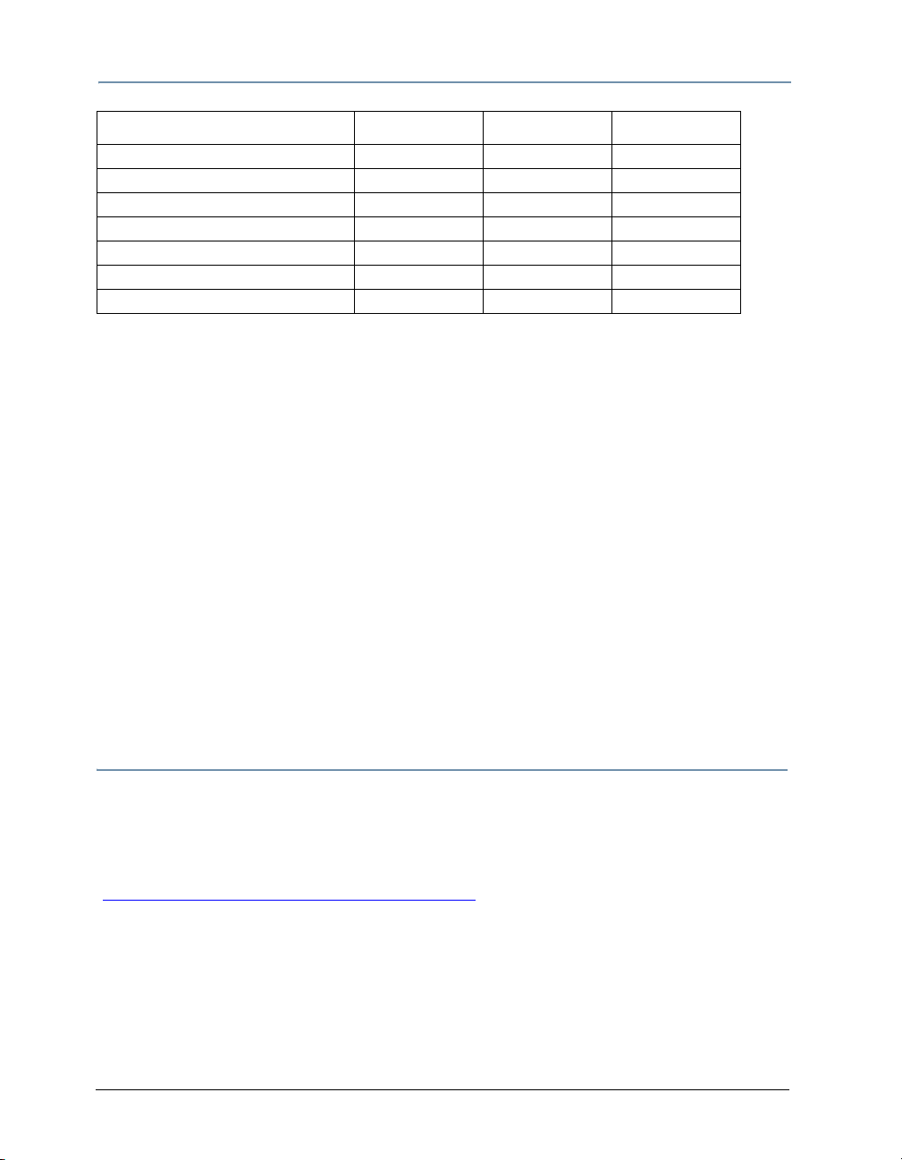
Catalyst Media Server Layers are designed to be controlled in a DMX-512 environment,
The software’s user interface is used for configuration and diagnostic purposes and can
also define presets for standalone operation. Media selections and manipulations can be
accomplished by and recorded to a lighting controller. User-defined presets can be
triggered with a computer keyboard, mouse or touchscreen.
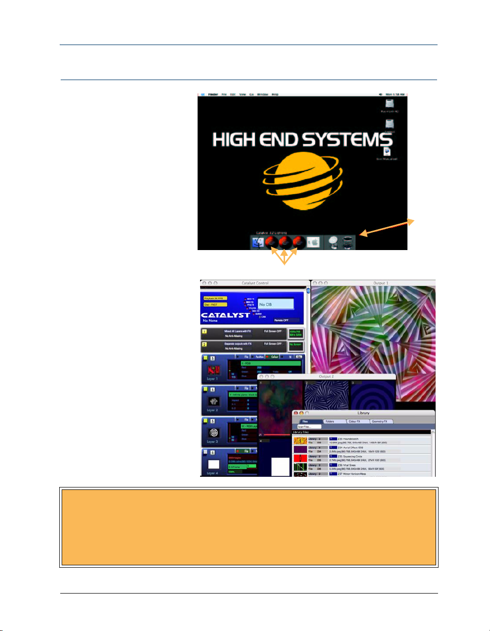
Figure 1: Catalyst Pro Software User Interface Display Screens
Catalyst® V3 Media Server User Manual 1
Page 18
System Overview
Selecting Media for Playback
Any content to be played back from the Catalyst Media Server is stored within computer
folders accessible from the application. The folder names begin with a three-digit number
from 000-253. This is known as the folder’s index number and corresponds directly to a
DMX value for the Library parameter. For example, when the DMX value of the Library
parameter is 11, the selected folder is the 011 Artbeats folder.
Similarly, the files in each Library file folder have names beginning with a three-digit
index number from 000 to 255. Each file’s index number corresponds directly to a DMX
value for the File parameter DMX channel. Adjusting the DMX value of the File
parameter on a lighting console selects a file from the active folder for playback.
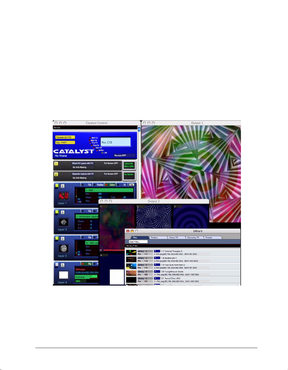
Working with Layers
Catalyst layers have a fixed priority order of
visibility, similar to sheets stacked back-to-front. A
layer with higher priority is in front of those with
lower priority. Layer 1 is at the back of the stack
(lowest priority), and all other available layers are
stacked in front of it in numerical order. Reducing a
layer’s Intensity parameter DMX value reveals the
layer behind it in the stack.
Note: Different versions of Catalyst software
support a different number of layers.
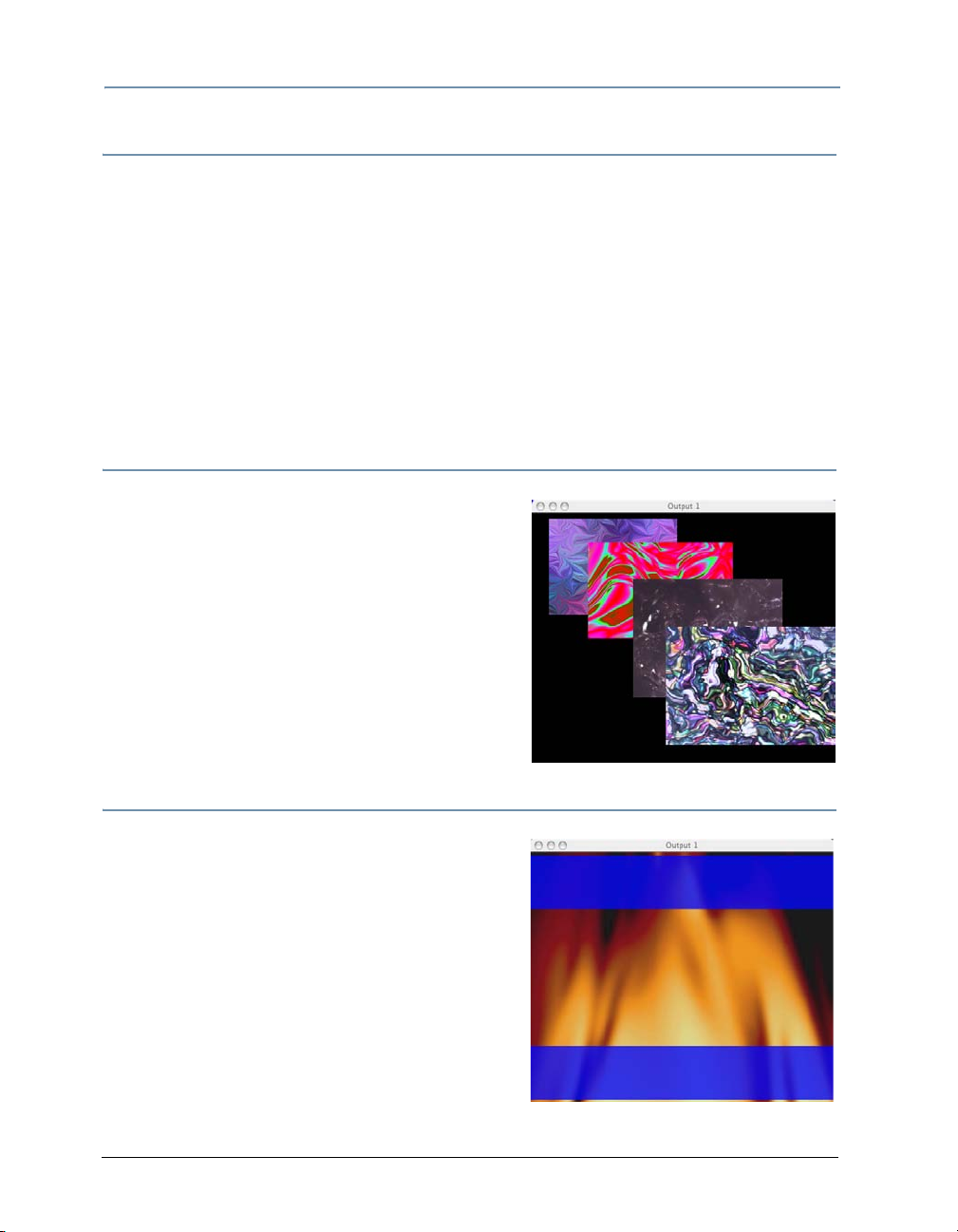
Software Security
High End Systems uses a USB dongle to prevent
unauthorized copying of Catalyst software. Factory
configured Catalyst Media Servers have a dongle
internally installed. Software only versions of the
application require a USB dongle plugged into one
of the PowerMac USB ports.
When the USB dongle is not detected by the
Catalyst software, blue bars will appear at the top
and bottom of both outputs.
Reconnecting the USB dongle will remove the blue
bars.
2 Catalyst® V3 Media Server User Manual
Page 19
Chapter 2:
QuickStart
This Chapter describes the steps to quickly setup and begin using a Catalyst Media Server
system. These instructions also ship with your product as a Startup Sheet for the model
you purchased. If you purchased a Software Only version of the product, setup
instructions shipped with your product. For information on configuring hardware to run
Catalyst Media Servers software, visit the High End System website support section
[http://www.highend.com/support/digital_lighting/catalystsupportguide/].
Media Server Setup
Unpacking the Roadcase
Unlatch and remove the top lid from the roadcase.Verify that the following contents are
stored in the lid and remove any you need for your application:
•LCD monitor
•Keyboard
•Mouse
• IEC TO 110v Adapter to attach an additional
monitor or device like a firewire drive to the power
conditioner in the server rack
• IEC 220v power cord optional for 220v applications
• USB Serial Adapters: One RS232 for serial devices
and One RS422 for Deck Control
• A Mac G5 power cord and phone cable (only needed if
you upgrade your G5 computer in the future)
• Documentation for the G5, Power Conditioner, VDA, USB PCI CD, and a Catalyst
Software CD-ROM
Top Lid
Server Rack
Base
Inspecting Your Catalyst Media Server
As you unpack the Media Server rack, verify that it is undamaged. If the product is
damaged or parts are missing, notify both the shipping company and your sales agent
immediately.
Before returning merchandise, contact your High End Systems dealer/distributor for a
Return Material Authorization (RMA) number. The factory cannot accept goods shipped
without an RMA number. Return a damaged product for repair in its original roadcase. High
End Systems assumes no responsibility for products damaged during transport.
Catalyst® V3 Media Server User Manual 3
Page 20
CHAPTER 2
A
T
A
LY
S
T
A
T
A
LY
ST
A
T
A
LY
ST
A
T
A
LY
ST
QuickStart
See “Product and Safety Information” for more information on warranties provided by
High End Systems for your product.
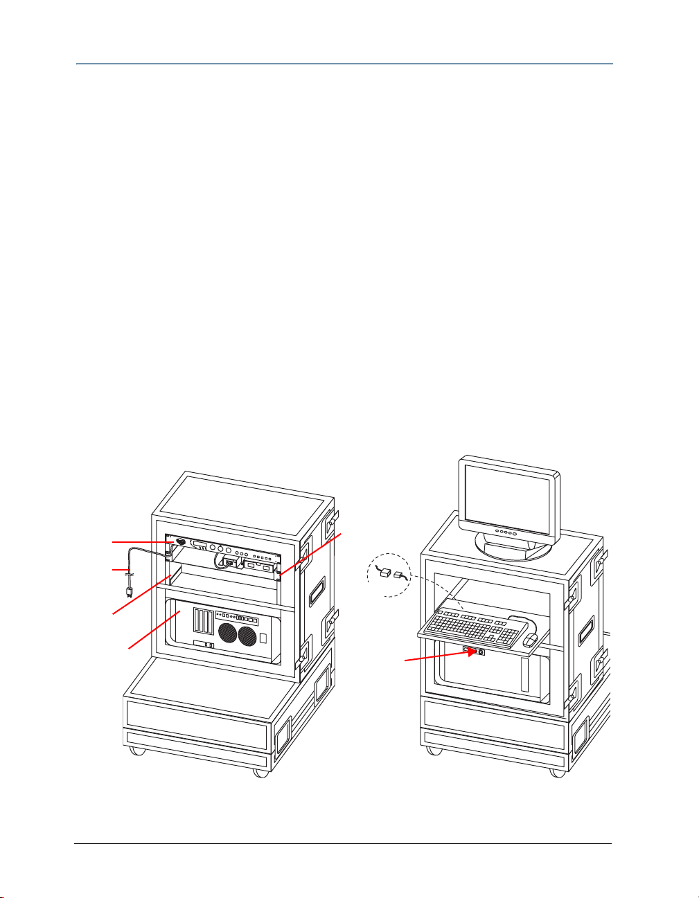
Setting up the Server Rack
1. Position the server rack upright on a platform constructed by latching the lid and the
roadcase base together.
2. The server rack contains a PowerMac® G5, the Catalyst Interface Box (CIB) a power
conditioner and a Digital Video Amplifier (VDA).
• The Catalyst DV model utilizes an Extron® VDA
• The Catalyst Pro version contains a DV1 Dual VDA
3. Set the LCD monitor on top of the server rack with the screen facing front and plug the
monitor power cord from the rack into the back of the monitor.
4. At the front of the server rack, pull the keyboard shelf out until it stops.
5. Plug the keyboard into the white USB connector port attached to the keyboard shelf.
6. Plug the mouse's USB plug into either of the two USB ports on the keyboard's back
edge.
TIP: For better performance, use the optical mouse on a non-reflective
surface instead of the keyboard tray.
CIB
C
C
C
C
A
A
A
A
T
T
T
T
A
A
A
A
LY
LY
LY
LY
S
ST
S
S
T
T
T
Monitor Cable
Power
Cord
USB
DV1
MacG5
REAR
Start Button
FRONT
Catalyst Pro Media Server Rack Setup
4 Catalyst® V3 Media Server User Manual
Page 21
CHAPTER 2
QuickStart
Hardware Connections
Catalyst Media Server models feature Dual or Single Output capability. Use the hardware
setup for your model.
Connecting Preview Monitors and Outputs
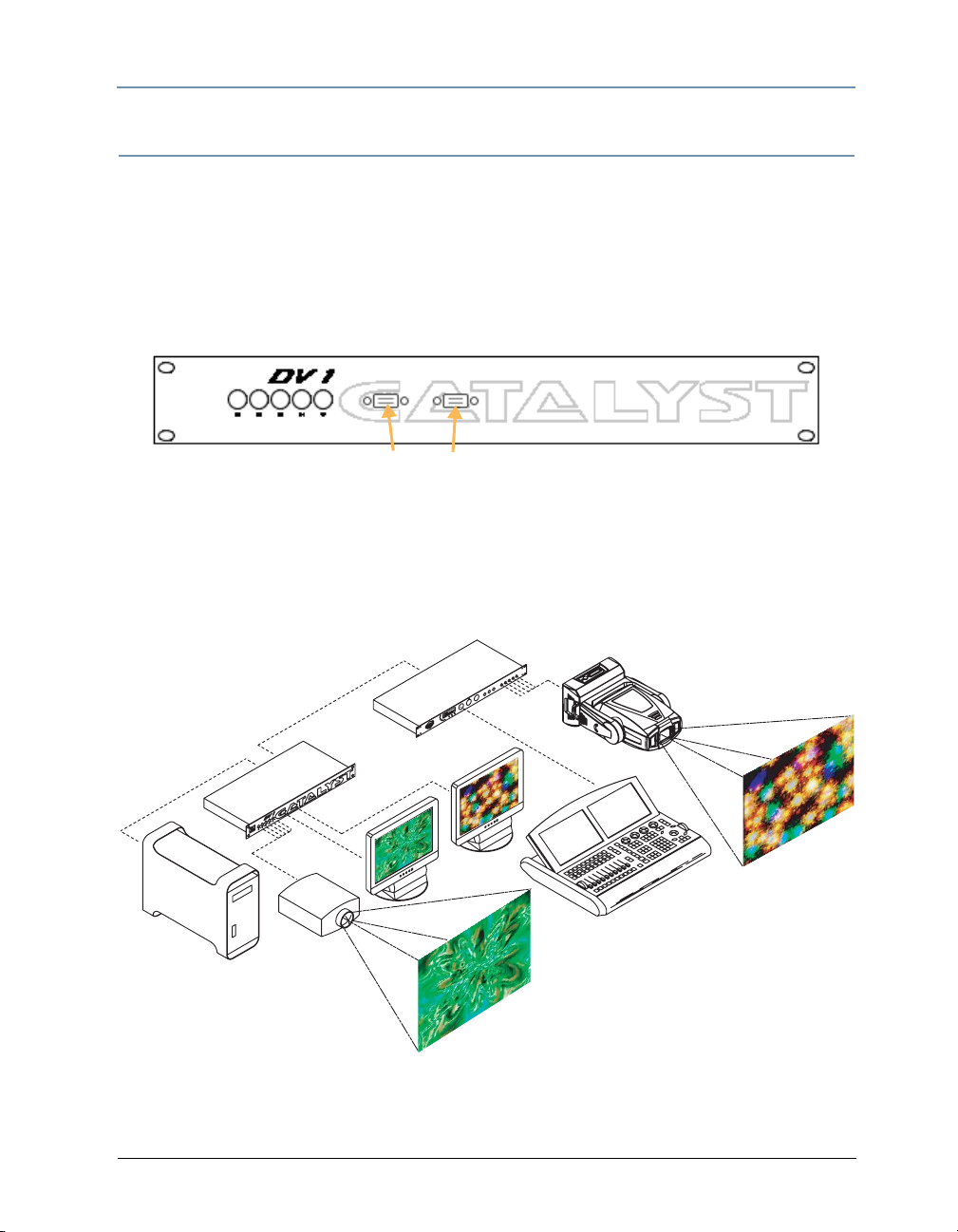
Catalyst Pro Dual Output Versions
1. Locate the DV1 (VDA) on the back of Catalyst Media Server rack.
P1 and P2 Monitor Ports
2. Plug the PowerMac LCD monitor data cable to the P1 monitor port on the DV1. If you
are using two preview monitors, connect the second monitor to the P2 monitor port.
3. Connect the device you want to designate as Output 1 to the RGBHV connectors on the
DV1.
4. Connect a second Output device to the RGBHV connectors on the CIB
DV1
G5 Output 1
Catalyst Pro connected to two output devices and utilizing two monitors
Catalyst® V3 Media Server User Manual
CIB
Output 2
Monitors
DMX
Console
5
Page 22
CHAPTER 2
QuickStart
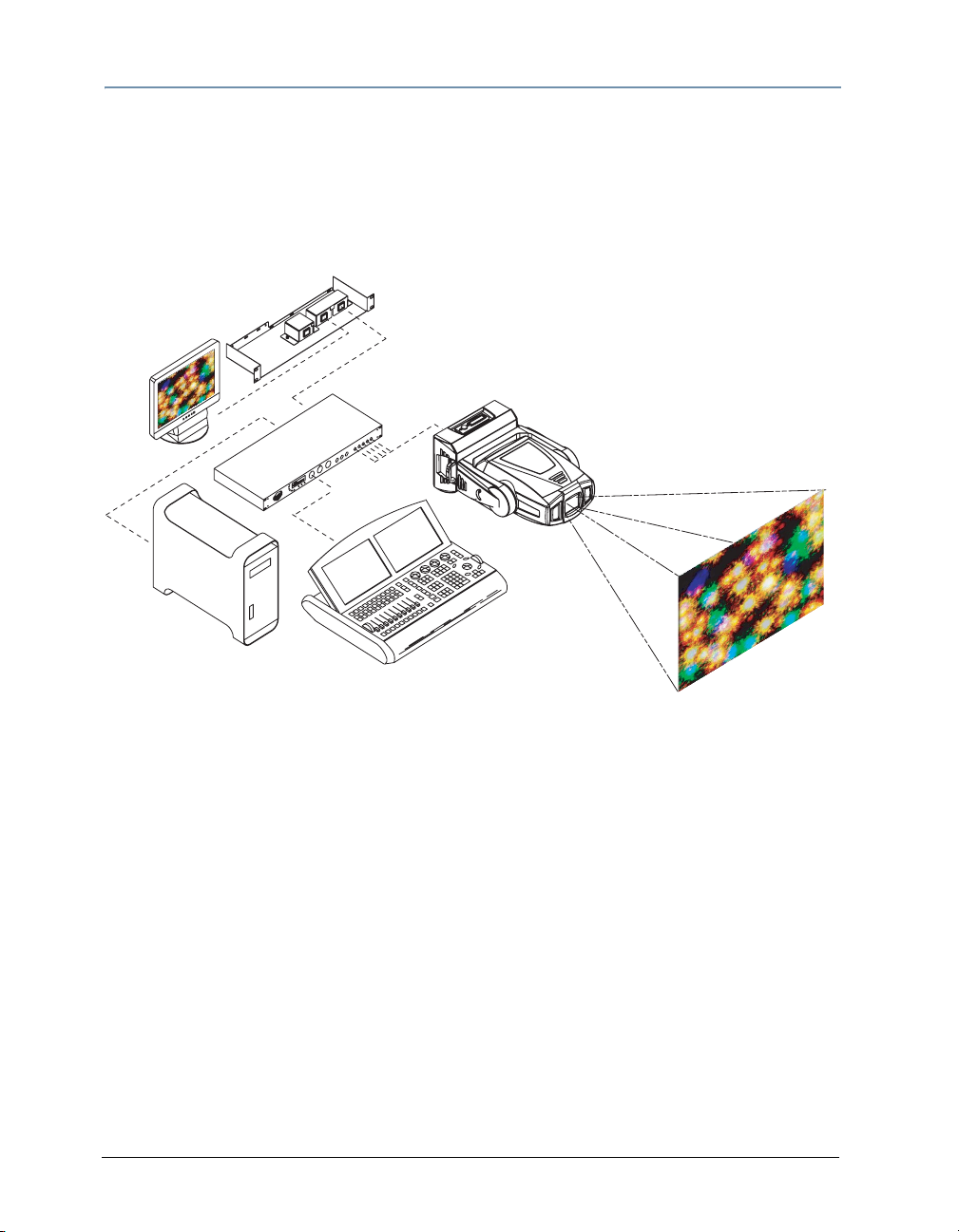
Catalyst DV Single Output Versions
1. Locate the Extron Video Distribution Amplifier (VDA) on the back of Catalyst Media
Server rack.
2. Plug the PowerMac LCD monitor data cable into the local monitor port on the VDA.
3. Connect an Output device to the RGBHV connectors on the CIB.
VDA
Output 1
Monitor
CIB
Media
Server
DMX Console
Catalyst DV Connected to a DL1 digital light for output and utilizing an emulation monitor
Connecting the Media Server to a DMX-512 Link
1. Connect the male XLR connector of a DMX data cable to the lighting controller’s
“DMX out” connector.
2. Connect the data cable’s female XLR connector to the “DMX in” connector of the
Catalyst Interface Box (CIB).
6 Catalyst® V3 Media Server User Manual
Page 23
Catalyst Software Application Setup
At the front of the Catalyst
Media Server rack, press the
PowerMac G5power button to
turn on the computer. The
desktop appears with icons for
the Macintosh HD, the Content
drive and the User Manual (in
.pdf format).
1. Move the mouse pointer to
the bottom of the screen. A
strip of icons forming the
Dock will pop up that
includes three Catalyst
icons. Each Catalyst icon is
connected to a content
format optimized for
specific applications
(Lighting, NTSC or PAL).
Icons for Catalyst Software versions
CHAPTER 2
QuickStart
Dock
2. Move the mouse over the
version you want to select
and click once to launch the
application.
The application ships from the
factory set to open the Catalyst
windows upon launch. If the
windows aren’t open on your
desktop, you can access them
via the Windows pull down
menu at the top of the monitor
display.
BACK UP THE CONTENT DRIVE
High End Systems recommends that you back up your content drive to a
firewire drive or other media. The drive contains over35GB of content files. As
an option, you can purchase Content backup on DVDs from High End Systems
by contacting Customer Service at 800.890.8989.
Catalyst® V3 Media Server User Manual
7
Page 24
CHAPTER 2
QuickStart
Configuring the Catalyst Software
The following steps give you a basic default startup configuration for the Catalyst Pro 8layer software version. Your version may have fewer layers or fewer outputs, but the
general steps are the same for all Media Server Software.
Choose Output Options
Catalyst Pro Media Servers can display independent views of the Layer content on each
output. Catalyst DV and Xpress software versions have single output capability and the
monitor emulates what is being projected from the output device.
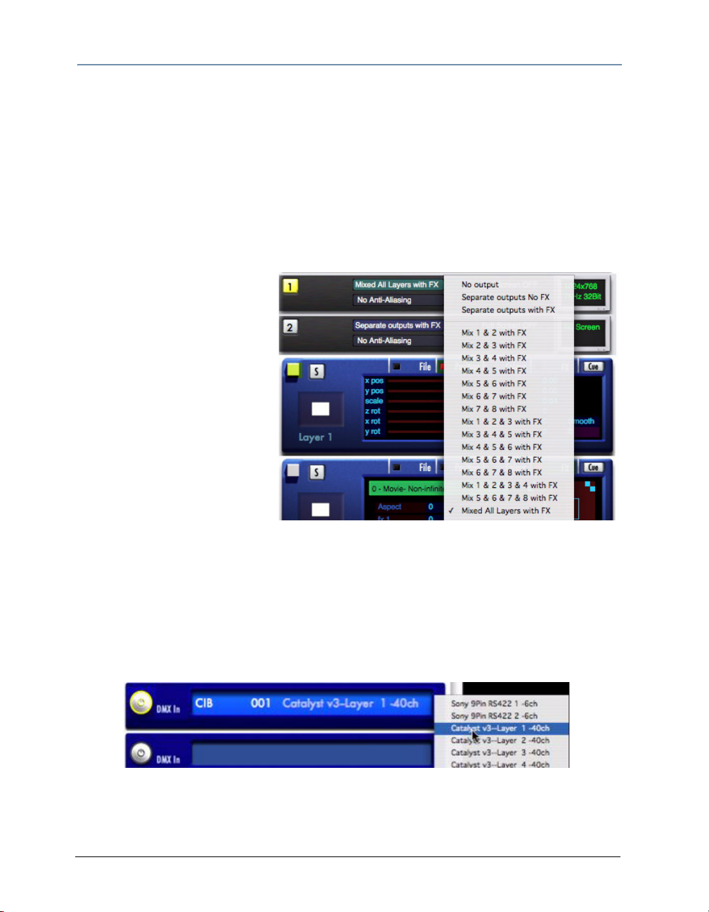
To configure Dual Outputs:
1. Locate the Output 1 panel in
the Catalyst Control Window.
Click the top field in of the
Output 1 panel as shown to
pop up a menu.
2. Highlight Mixed All Layers
with FX and click to select.
3. Locate the Output 2 panel in
the Catalyst Control Window
and select Separate Outputs
with FX.
Set DMX Start Channels for Layers
To assign a DMX start channel to a Media Server layer:
1. Scroll down the Catalyst Control Window until the first DMX In panel is visible.
2. Turn on the DMX In panel by clicking the On button on the left side of the panel. The
center circle and outside edge of the button turn yellow.
3. Select a layer or serial device for that DMX In panel.
8 Catalyst® V3 Media Server User Manual
Page 25
CHAPTER 2
QuickStart
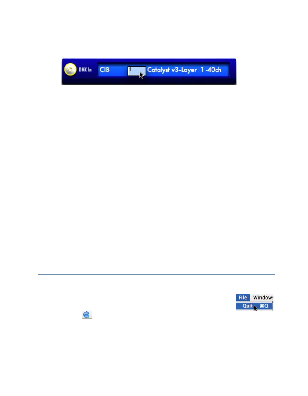
4. Click in the number field to type in the start channel. Remember that each layer
requires an uninterrupted range of 40 channels for independent DMX control.
5. Patch each layer to your lighting console using the DMX Start Channels assigned with
the Catalyst DMX In panels.
TIP: Each layer's DMX patch within the lighting console must match the
corresponding layer's DMX Start Channel in the DMX In panel. For more
information on setting DMX Start channels, see
512”.
Now you are ready to use your lighting console to select and manipulate content on the
computer's hard drive.
you are new to Catalyst Media Servers.
Chapter 3: on page 11 contains tutorials that you will find helpful if
“Understanding DMX-
Projecting Images Using Full Screen Mode
Selecting Full Screen Mode lets you view the output on the monitor as it is displayed
through the output device you are using. With Full Screen mode off, your output device
projects the desktop display.
Press A on the keyboard to assign Output 1 to Full Screen mode.
Press S on the keyboard to leave full screen mode.
Once you select Full Screen mode, the output remains a black screen until the Catalyst
Media server receives DMX values from a lighting console.
System Shutdown
1. If you are in Full Screen mode, press S to disable.
2. Close the Catalyst application by clicking on the File menu at the top
of the desktop and selecting quit.
3. Click on the menu option and choose Shut Down.
Catalyst® V3 Media Server User Manual
9
Page 26

CHAPTER 2
QuickStart
10 Catalyst® V3 Media Server User Manual
Page 27
Chapter 3:
Tutorials
The following lessons provide a quick introduction to programming Catalyst with a
lighting console. General knowledge of your lighting console is required to complete these
tutorials. For information on programming without a console, see Chapter
Note: The sample content files in these tutorial lessons were selected from content
shipping May 1, 2004.
Lesson 1: Still Logo on Moving Background
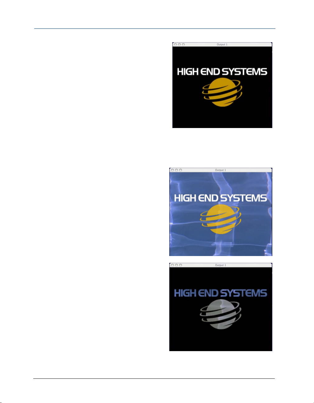
In this lesson you will set a movie playing on Layer 1; then, using Layer 2, superimpose a
still image of the High End Systems logo over the movie playing onLayer 1.
Set up Layer 1
1. On your lighting console, select Layer 1. Set
the Intensity parameter for Layer 1 to a DMX
value of 255(100%).
2. Set the Library parameter to a DMX value of
11. This should select the preloaded Catalyst
Library folder 011 Artbeats.
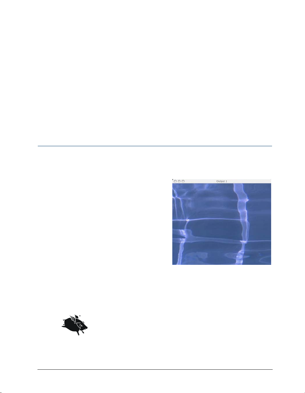
3. Set the File parameter to a DMX value of 3.
This selects the movie file numbered 003 in
Library folder 011. On the Catalyst Output 1
display you should see the first frame of movie
file 003WA 114, a pale blue image of rippling water.
4. On your lighting console, set the Play Mode parameter to a DMX value of 2 or Play
Loop Forward. The movie file will begin playing and the water will appear to be
rippling.
The Wholehog II uses eight character alpha-numeric labels to
describe values of the Play Mode parameter. For this exercise,
select plloopfw.
The Wholehog III has a Mode menu with the Play Mode parameter
options on the slotted toolbar. Select Play Loop Forward.
18: “Presets”.
Catalyst® V3 Media Server User Manual 11
Page 28
CHAPTER 3
Tutorials
Add the Logo
5. On the lighting console, select Layer 2. Set the
Intensity parameter for Layer 2 to a DMX
value of 255(100%). The Catalyst Output 1
screen should change to solid white.
6. Set the Library parameter to a DMX value of
0. This should select the preloaded Catalyst
Library folder 000 (HES Lithos).
7. Set the File parameter to a DMX value of 71
(HES-logo-color). This selects the movie file
numbered 71 in Library folder 0. You should
see the High End Systems logo on the Output 1 window.
Turn Layer 2 Background Transparent
Now you’ll apply a color effect that turns the
black background of the Layer 2 logo
revealing the movie file playing on the underlying
Layer 1.
transparent,
8. With Layer 2 still selected on your lighting
console, set the Color Effects parameter to a
DMX value of 3 (the color effect named
Transparent Blacks). The black background
of the High End Systems logo will become
transparent and reveal the rippling water
movie playing on Layer 1.
9. Now change the Color Effects parameter to
a DMX value of 4 (the color effect
Transparent Whites). The non-black
portions of the High End Systems logo
should become transparent and reveal the
rippling water movie playing on Layer 1.
12 Catalyst® V3 Media Server User Manual
named
Page 29
CHAPTER 3
Tutorials
Lesson 2: Crossfading Between Layers
Once you display content on different Catalyst layers, you can fade the layers in and out
using the Intensity parameter. This creates a crossfading or dissolving effect between
layers.
In this lesson, you’ll play a movie on Layer 1 and record it in your lighting console as a cue
or look. Then you’ll build and record another cue with a three-second crossfade to a
colorful movie playing on Layer 2.
Set Up First Cue
1. Clear or remove any information from Lesson
1 in your console’s programmer or editor.
2. On your lighting console, select Layer 1. Set
the Intensity parameter to a DMX value of
255(100%).
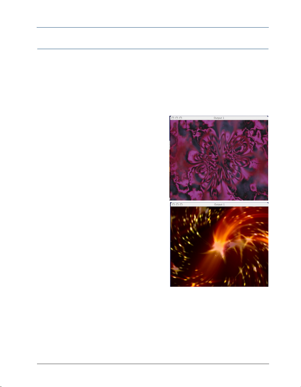
3. Setting DMX values in the Library and File
parameters as in Lesson 1, select Library 12
(Beacon DigiGobos), File 7 (loopedroseA).
4. Set the Play Mode parameter to a DMX value
of 2 (Play Loop Forward). The
playing.
5. On your lighting console, select Layer 2. Set
the Intensity parameter to a DMX value of
255(100%). The Output 1 screen changes to
solid white.
6. Using the preloaded Catalyst content, select
Library 14 (Beacon DigiGobos), File 4
(swirlstars2). Set the Play Mode parameter to
a DMX value of 2 (Play Loop Forward). The
animation will begin playing on Output 1.
7. Still on Layer 2, change the Intensity parameter to a DMX value of 0 (0%). Layer 2
will disappear, revealing the movie playing on Layer 1.
8. Using your lighting console’s method of recording cues or looks, record the above
DMX settings as Cue 1 on your lighting console.
movie starts
Catalyst® V3 Media Server User Manual
13
Page 30
CHAPTER 3
Tutorials
Setup the Second Cue and Playback
9. On your lighting console, select Layer 2. Change the Intensity parameter to a DMX
value of 255 (100%).
10. Use your lighting console’s cue timing options to assign a 3 second time value to the
Intensity parameter.
11. Record these DMX settings and timing information as Cue 2 on your lighting console.
12. Clear your lighting console’s programmer or
editor. The Catalyst Output 1 screen
change to all black.
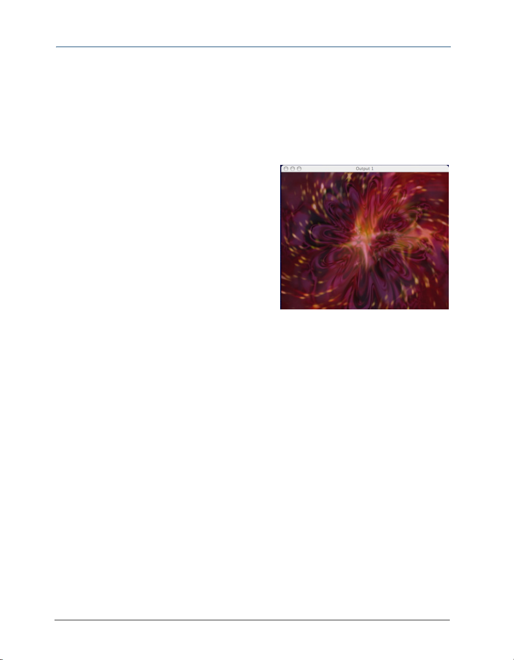
13. Using your lighting console, playback the Cue
1 created above. The first movie plays on the
Output 1 window of the Catalyst system.
14. Using your lighting console, playback the Cue
2 created above. Output 1 shows Layer 1
crossfading to Layer 2 over a 3-second interval.
15. When finished, follow your lighting console’s
procedure to turn off or release any cues that
are playing back.
should
14 Catalyst® V3 Media Server User Manual
Page 31
Lesson 3: Image Color and Scale
In this lesson, you’ll use a Layer’s Position Controls
to make an image appear to
distance. In addition the Layer’s Color Controls are
used to color the image.
Set up Layer 1
1. Clear or remove any information in your
console’s programmer or editor.
2. On your lighting console, select Layer 1. Set
the Intensity parameter to a DMX value of
255(100%).
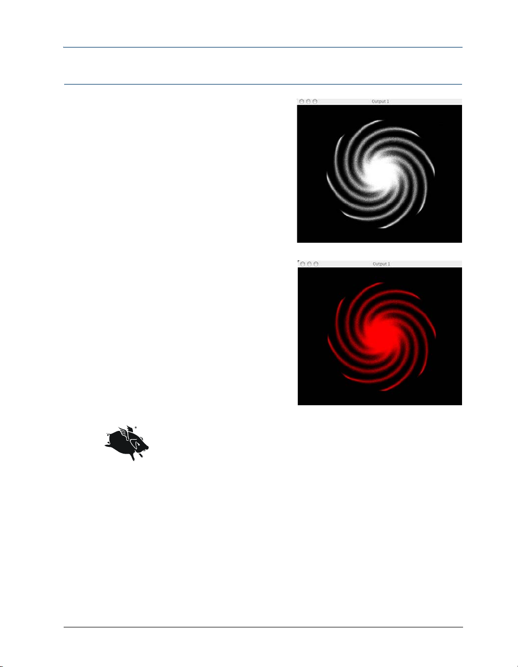
3. Select Library 0 (HES lithos) and File 5
(comets). The image will be displayed
Output 1 window.
4. Change the Red parameter to a DMX value of
255, and the Blue and Green parameters to a
DMX value of 0. This changes the image to a
red spiral galaxy
zoom away into the
on the
CHAPTER 3
Tutorials
5. Using your lighting console’s method of
recording cues or looks, record the above DMX
settings as Cue 1 on your lighting console.
On a Wholehog console the Red, Green, and Blue parameters
are labeled as Cyan, Magenta, and Yellow. The parameter values
displayed are in terms of percentage where 0% equals a DMX
value of 255 and 100% equals a DMX value of 0. On a Wholehog
console, set the Cyan parameter to 0% and the Magenta and
Yellow to 100% to create a red color.
Set Layer 1 Rotation, Position, and Scale
6. Adjust the DMX value of the Z Rotation parameter so the Layer image starts spinning
slowly—say 10 rotations per minute.
7. Adjust the DMX value of the X Position parameter (not the X Rotation parameter) to
move the image to the left edge of the Output 1 window, so it is barely visible.
8. Adjust the DMX value of the Y Position parameter to move the image straight up to
the top left corner of the Output 1 window, so only the corner is visible.
Catalyst® V3 Media Server User Manual
15
Page 32

CHAPTER 3
Tutorials
9. Adjust the DMX value of the Scale parameter to the midpoint of its 16-bit DMX value
range. This shrinks the Layer’s image to a tiny point.
On a Wholehog console, the 16-bit DMX values of the
Scale parameter are displayed are in terms of
percentage. 50% is equal to the midpoint of the 16-bit
DMX range.
10. Use your lighting console’s cue timing options to assign a 3-second time value to the
Z-axis Rotation, Y position, and Scale parameters. Record the above DMX settings
and timing information as Cue 2 on your lighting console.
Playback
11. Clear your lighting console’s programmer or editor. The Catalyst Output 1 window
should change to all black.
12. Using your lighting console, playback the Cue 1 created above. The red spiral galaxy
appears on the Output 1 window of the Catalyst system.
13. Using your lighting console, playback the Cue 2 created above. The red spiral galaxy
will spin and shrink away on the Output 1 window.
14. When finished, follow your lighting console’s procedure to turn off or release any
cues that are playing back.
16 Catalyst® V3 Media Server User Manual
Page 33

CHAPTER 3
Tutorials
Lesson 4: Trails
The Trails parameter creates an afterimage that follows an image as it moves, then slowly
fades away.
Understanding Trails
Unlike other Catalyst 3 effects, you can apply Trails only to Layer 1, the bottom Layer in
the Layer stack. However, the Layer 1 Trails effect can also encompass content from
higher layers, as long as Layer 1 is visible beneath them. For example assigning
transparency to Layer 2 makes it subject to Layer 1’s Trails effect
Trails parameter settings for layers other than Layer 1 are ignored and do
not alter layers.
Applying Trails to Layer 1
1. Clear or remove any information in your
console’s programmer or editor.
2. On your lighting console, select Layer 1. Set
the Intensity parameter to a DMX value of
255(100%).
3. Select Library 2 (HES Digital Aerials 2)and
File 124 (threaded X). Set the Play Mode
parameter to a DMX value of 0 (In Frame).
Using the preloaded Catalyst content, you
should now see an animation with two rotating
squares playing in the Output 1 window.
4. Assign the DMX value of the Color Effect
parameter to 3 (transparent blacks).
5. Adjust the DMX value of the Tra il s parameter
to 255(100%). As the movie plays, each frame
will leave an afterimage that slowly fades
away.
Catalyst® V3 Media Server User Manual
17
Page 34

CHAPTER 3
Tutorials
Adding Trails to Layer 2
6. On your lighting console, select Layer 2. Set
the Intensity parameter to a DMX
255(100%).
7. Select Library 0 (HES lithos) and File 28
(comet). Using the preloaded Catalyst content,
you should now see a greyscale pinwheel
image on Output 1.
8. Adjust the DMX value of the Z Rotation
parameter so the Layer 1 image starts
spinning slowly— 20 rotations per minute, for
example.
9. Assign the DMX value of the Color Effects
meter to 3 (transparent blacks). Yo u w ill
para
now see the Trails effect from Layer 1 is
applied to Layer 2.
10. When finished, clear or remove any
information from the above lesson in your
lighting console’s programmer or editor.
value of
18 Catalyst® V3 Media Server User Manual
Page 35

CHAPTER 3
Tutorials
Lesson 5: Shutters
Any Layer can be used to shutter or crop content on underlying layers using the Shutter
settings of the Visual Effects parameter.
Understanding Shutters
When a shutter Visual Effect is activated on a layer, that layer changes to a shutter only
layer. Any assigned content for the layer will not be displayed. Instead, an adjustable
transparent frame is displayed above underlying layers. A shutter Visual Effect will not
function on Layer 1.
Once a layer becomes a shutter only layer, the Keystone Correction parameters can be
used to adjust the frame’s shape. In addition the X, Y, and Z Rotation, X and Y Position,
and Scale parameters modify the appearance of the shutters.
Set up Layer 1
11. Clear or remove any information in your
console’s programmer or editor.
12. On your lighting console, select Layer 1. Set the
Intensity parameter to a DMX value of
255(100%).
13. Adjust the Library and File parameters on your
console to select Library 12 (Sean Bridwell
Textures), File 8 (loopedsnakes1).
14. Set the Play Mode parameter to a DMX value of
3 (Play Loop Reverse).
Add Shutters with Layer 2
15. On your lighting console, select Layer 2. Set the
Intensity parameter to a DMX value of
255(100%).
16. Set the Visual Effects parameter to a DMX
value of 70 (Shutter -Black).
17. Adjust the Scale parameter until the Output 1
window displays a transparent square in a
black background.
Catalyst® V3 Media Server User Manual
19
Page 36

CHAPTER 3
Tutorials
18. Adjust the eight Keystone Correction
parameters to change the shape of the
shutters.
19. Adjust the Z Rotation parameter to rotate the
shutters.
20. When finished, clear or remove any
information in your lighting console’s
programmer or editor.
20 Catalyst® V3 Media Server User Manual
Page 37

Chapter 4:
Windows Menus
The Catalyst Interface
The Catalyst Graphical User Interface is composed of the Catalyst
Control, Library, and
the Xpress version).They are accessed through the Windows Menu at
the top of the screen. The user interface provides configuration,
command and preview functions.
Selection Tools
Three mechanisms are used to select and adjust interface settings:
Menu A pop-up menu lets you scroll through the list to the desired file or setting. The
library and file selection menus under the File tab, color effects under the Color tab, and
FX effect under the FX tab all use menus.
Slider Moving a slider left or right, or up or down, changes the parameters. Intensity
adjustments on the Color tab, and all the adjustments on the Position tab, use sliders.
Numerical Slider Where numerical values appear in a field, such as playback speed under
the File tab, or the red, blue and green settings under the Color tab, click the field while
holding down the mouse button. Moving the mouse up and down to raises or lowers value.
The following sections outline each Window’s components and general functionality and
references other sections of this manual with more detailed functional descriptions.
Two Output windows (One Output window for
Catalyst® V3 Media Server User Manual 21
Page 38

CHAPTER 4
Windows Menus
Catalyst Control Window
Components
The Catalyst Control Window
contains the following panels:
CIB Paneldisplays status of the
CIB connection and switches sync
functions.
Output Control panelssets the
output display. Catalyst Pro and
Catalyst DV have dual outputs,
Catalyst Xpress has one output
available.
Layer Panels allow preview and
control of DMX parameters for
each available layer. Catalyst Pro
provides eight layers; Catalyst
DV, five; and Catalyst Xpress,
three.
DMX Insets DMX start channel
values for layers, as well as the
following:
Midi Show Control Input Triggeris used in conjunction with Presets
Video Inputswitches a layer's content source from the Media Server hard drive to a video
feed input. Catalyst Pro and DV software provides two video inputs. Catalyst Xpress has
one video input.
Sound Input activates audio input. All versions of Catalyst software provide this feature.
Custom Serial inputs configures serial devices. Four serial inputs are available in
Catalyst Pro software and three in the Catalyst DV version.
Midi Time Code Input is available in Catalyst Pro and Catalyst DV versions
22 Catalyst® V3 Media Server User Manual
Page 39

CHAPTER 4
Windows Menus
CIB Panel
Turnkey Catalyst systems utilize a Catalyst Interface Board (CIB) to connect to a DMX
console. User configured systems utilizing Catalyst Software only versions may substitute
an ArtNet box, see the High End Website for additional configuration information at
http://www.highend.com/support/digital_lighting/catalystsupportguide/index.asp
When a (CIB) is connected properly to the media server, the mini display window will say
CIB OK. If the CIB is not hooked up, it will read
versions of Catalyst.
Figure 4-1 CIB Setting Pane
No CIB CIBs are used with turnkey
The Name field is editable and is used to identify the local media server on network of
multiple servers.
The Remote Off/On field configures synchronization functionality. For more information
on synchronizing output between servers, see
Multiple Servers on page 175.
Output Control(s)
Content can be viewed locally on a monitor before sending it to a Catalyst DL1 fixture or
other video output device. The Output Control panes configures each layer or stacked
layers with or without effects on either or both output screens at a selected screen
resolution. For more detailed information, see
The Output On/Off button turns Output Windows 1 and 2 On (yellow) and Off (white).
Output Windows field provides a variety of Output display options on each output
individually depending on available in your version of Catalyst Software.
All layers with effects shows the composite of the individual layer effects. The most
common output window setting is to show all four layers mixed with FX in Output
Window 1, and Separate Outputs with FX on Output 2.
The Anti-aliasing popup field provides options for smoothing the edges of the outputted
image.
Note: Anti-aliasing may slow the speed of FX for some images.
Catalyst® V3 Media Server User Manual
Configuring Output Displays on page 34.
23
Page 40

CHAPTER 4
Windows Menus
Full Screen Display On/Off turns the full screen display mode on and off. The hot key to
turn on full screen display for Output 1 is A, and the hot key to turn it off is S.
The small monitor image displays the current resolution, screen refresh, and bit depth of
the attached monitor is. If a second monitor is not hooked up it will say
Output Windows Full Screen Display
No Screen.
On/Off button
Aliasing
Display Config
Layer Panel
When using a DMX console to control a Catalyst Layer, all settings within the Layer panel
will automatically adjust in real time to reflect the current DMX values sent from a
lighting console.
With the DMX In panels turned off, Preset programming allows the user to set values in
each of this panel’s tabs, see
Active Button
Solo Button
Media Thumbnail
Layer Name field
The Solo function allows activates only the selected layer and all others are ignored. This
test function can be used to isolate one Layer from the others. Clicking the Solo button
will activate or de-activate the
The far left portion of the Layer Panel displays a thumbnail (if available) of the currently
selected media for the layer.
Each Layer can be named by clicking on the Layer Name field, typing in a name and
pressing ENTER. This function is primarily for personal organization purposes.
Creating a Preset on page 144
Solo function
See the following for more information about parameters displayed in the layer panels:
• File tab fields —Chapter 6: Media Playback on page 41.
• Position tab fields — Chapter 7: Movement and Size on page 47.
• Color tab fields — Chapter 8: Intensity and Color on page 55, and Chapter 9: Strobing
and Trails on page 89.
• FX tab fields — Chapter 10: Visual Effects on page 91, and Chapter 11: Keystone and
Shutters on page 117.
24 Catalyst® V3 Media Server User Manual
Page 41

CHAPTER 4
Windows Menus
DMX In Panel
Use the DMX In panels to patch layers as well as other inputs for DMX control. There are
multiple DMX In panels in each Catalyst Software Version to allow setting DMX start
channel values for one of the following Devices:
•Layer image
•Layer volume control
• Preset Trigger
• RS 422 devices
• Serial Trigger
• ArtNet protocol
Yellow outline
indicates DMX On
Choose CIB DMX
interface or ArtNet
Type in Start
Channel number
Select Device
Video Input
Video feeds can be manipulated with the Layer’s parameters in the same manner as
content played back from the hard drive. For more information, see
127.
On Button
Video
Input Field
Video Input on page
Sound Input
Catalyst Pro, DV and Xpress versions can all convert audio to a visual waveform. The
waveform can then be manipulated with the Layer’s parameters in the same manner as
content played back from the hard drive.activates audio input. This panel activates the
audio input. For more information on the audio feature, see
Audio Input on page 123.
Click on the round On/Off button to activate the Video Input panel
Catalyst® V3 Media Server User Manual
25
Page 42

CHAPTER 4
Windows Menus
Custom Serial Inputs
The Catalyst Media Server can control peripheral devices such as video switchers or
projector shutters through the PowerMac’s Universal Serial Bus (USB) ports. This feature
lets non-DMX controlled devices coordinate automatically with events and images in your
For more information, see Chapter 15: Serial Control on page 129.
show.
Midi Time Code Input Catalyst Media Servers can receive MIDI timecode and a Layer’s
playback can synchronize to the timecode. This panel assigns the input. For more
information, see
Chapter 16: MIDI Timecode on page 135.
Device field
26 Catalyst® V3 Media Server User Manual
Page 43

CHAPTER 4
Windows Menus
Library Window
On the top of the PowerMac monitor, Click on Library within the
Windows menu to open
The Library window of the Catalyst Media Server has the following
functions.
• Lists and describes content files and folders available to the server
• Displays details about the Color and Visual Effects.
• Configures Library folder assignments
• Creates and edits Presets
Files Tab
Clicking on the Files tab on the top of the Library window displays the content currently
available to the server
the Library window.
.
Thumbnail
Folder Number
File Number
Assign Folder
File Name
File Statistics
Catalyst® V3 Media Server User Manual
27
Page 44

CHAPTER 4
Windows Menus
Folders Tab
Clicking on the Fold er s tab on the top of the Library window displays the folders
currently assigned as Library Folders. Additional folders from internal or external drives,
as well as network sources, can be assigned to Catalyst. Any properly labeled folders and
files in an assigned Library Folder become available content.
Folder
Assignment
Number
1. Click on a Folder assignment number to open the Choose a Folder window.
2. Browse to the drive and folder containing the content files and click Open.
28 Catalyst® V3 Media Server User Manual
Page 45

CHAPTER 4
Windows Menus
The Folde rs tab of the Library Window now displays the newly assigned folder.
3. Press the Scan Files... button to begin a scan of all available media files. The scanning
window will open and display the scan progress.
When the scan is complete the scanning window will close and the new media
becomes available to the Catalyst Media Server.
Note: Pressing Shift during a scan will perform a Quick Scan where no thumbnails
will be created.
Catalyst® V3 Media Server User Manual
29
Page 46

CHAPTER 4
Windows Menus
Color FX Tab
Clicking on the Color FX tab on the top of the Library window displays reference
information for the Color Effects parameter.
Colored fields indicate the functionality of other parameters associated with each effect.
For more information, see
Color Effects on page 57.
Geometry FX Tab
Clicking on the Geometry FX tab on the top of the Library window displays reference
information for the Visual Effects parameter. Colored fields indicate the functionality of
other parameters associated with each effect. For more information, see
Visual Effects on page 91.
30 Catalyst® V3 Media Server User Manual
Chapter 10:
Page 47

CHAPTER 4
Windows Menus
Presets Tab
The preset tab contains fields that allow the programmer to name, edit and store preset
created for programming without a DMX console. For detailed information, see
18: Presets on page 143.
Chapter
Catalyst® V3 Media Server User Manual
31
Page 48

CHAPTER 4
Windows Menus
Output Windows
The output windows (Two for
Catalyst Pro and DV versions, and
one for Catalyst Xpress software
version) allow the programmer to
view the content according to the
output selection criteria set in the
Catalyst Control Window’s
Output panel(s).
Depending on the system
configuration, these windows can
display a preview of the content
or emulate the actual output of
the local server.
For more information on
configuring the output windows,
Chapter 5: Output Displays on
see
page 33.
These windows also display the
diagnostic screens available in the
Catalyst software interface. For
detailed information, see
20: Diagnostic Displays on page
163.
Chapter
32 Catalyst® V3 Media Server User Manual
Page 49

Chapter 5:
Output Displays
The Catalyst Media Server supports two output signals. Each signal is split, and can be
displayed simulataneously on any output device (DL1 digital light, video projector, LED
wall, etc.) and a monitor display.
DV1 Video Distribution Amplifier
The Catalyst Media Server uses the DV1 dual video distribution amplifier to split and
amplify the PowerMac’s two video outputs for display on preview monitors as well as
output devices. In addition, five BNC video connectors labeled R, G, B, H, and V (RedGreen-Blue-Horizontal sync-Vertical sync) are provided to send Output 1 to a device using
high-quality 75-ohm video cable.
P1 and P2 Monitor PortsRGBHV BNC connectors
CAUTION!
Using a video cable longer than 250 feet (80 meters) can
degrade video performance.
Catalyst Interface Box (CIB)
The Catalyst Interface Box is an interface between the DMX console and the computer’s
Universal Serial Bus (USB) port. In addition, five RGBHV connections are provided to
send Output 2 to a device using high-quality 75-ohm video cable.
RGBHV BNC connectors
Catalyst® V3 Media Server User Manual 33
Page 50

CHAPTER 5
Output Displays
Configuring Output Displays
The Catalyst Control window contains the Output panels. Each panel can be activated
with the On/Off button in the top right corner of the panel.
On/Off button
1. Click on the monitor icon to pop up a menu of resolution
settings for the output. The display settings should match
those configured on the display device. Consult the
display device’s documentation for the recommended
resolution and refresh rate settings.
Monitor icon
2. Click on the Full Screen button to pop up a menu containing output screen settings.
Screen Setting Field
Full Screen ON: The selected output fills the entire screen on the output display.
Full Screen OFF. The selected output appears in a small window on the output display.
Goto Full Screen At Startup. When the Catalyst application is started, the selected output
will automatically enter Full Screen mode.
Startup Screen. Select screen display size for startup.
Note: High End Systems recommends using the “No Anti-Aliasing” option for all
display configurations
34 Catalyst® V3 Media Server User Manual
Page 51

CHAPTER 5
Output Displays
3. Click on the Output Settings field of the Output panel to open a pop-up menu and
select one of the options.
Output Setting Fields
All Catalyst Media Server software products contain the following Output Setting fields.
•No Output
• Separate outputs No FX displays all configured Layers simultaneously in a grid. Each
Layer displays only its content playback, and ignores all other DMX parameters.
• Separate outputs With FX displays all configured Layers simultaneously in a grid.
Each Layer displays its content with all DMX parameter settings applied.
• Mixed All Layers No FX displays all configured Layers stacked on top of each other.
• Mixed 1 & 2 with FX displays configured Layers one and two stacked together.
Depending on the number of layers for the Catalyst version, more layer combinations will
be available settings.
Catalyst® V3 Media Server User Manual
35
Page 52

CHAPTER 5
Output Displays
Output Configurations
Single Output with Redundant Monitor
VDA
Output 1
Monitor
CIB
Media
Server
Catalyst DV Single Output configuration
With Single Output versions, the monitor can only display whatever signal is being sent to
the output.
DMX Console
36 Catalyst® V3 Media Server User Manual
Page 53

Dual Output Device With Preview Monitor
CIB
DV1
Output 2
Monitor
Output 1
Media
Server
CHAPTER 5
Output Displays
DMX
Console
Dual Output with Preview Monitor
In this example, Output 1 displays all layers combined, and Output 2 displays each layer
individually for preview purposes.
Catalyst® V3 Media Server User Manual
37
Page 54

CHAPTER 5
Output Displays
Dual Outputs with Emulation Monitors
Output 2
DMX
Console
Media
Server
DV1
Output 1
CIB
P1 and P2
Monitors
Dual Output with Redundant Monitors
Output 1 and Output 2 each display individually assigned layers. Each monitor displays
the same image as its respective output.
38 Catalyst® V3 Media Server User Manual
Page 55

Dual Outputs with DL1 Dimming Control
CHAPTER 5
Output Displays
Output 2
DMX
Console
Media
Server
DV1
Output 1
CIB
P1 and P2
Monitors
Dual Output with DL1 output dimmer at 0
Output 1 and Output 2 each display individually assigned layers. Each monitor displays
the same image as its respective output. Using a DL1 digital lighting fixture or a projector
with remote shuttering controls, the output displays can be hidden from view and the P1
and P2 monitors behave as preview screens. Configure the Output panels the same as
Dual Outputs with Redundant Monitors.
Catalyst® V3 Media Server User Manual
39
Page 56

CHAPTER 5
Output Displays
Dual Outputs Widescreen Layers
Output 1 and Output 2 each display one half of the images from all assigned layers. Layer
selections are automatically split and assigned to an output.
CIB
Output 2
DV1
P1 and P2
Monitors
Media Output 1
Server
DMX Console
Combined outputs
Configure the Output panels as follows:
• Widescreen Layers Left for Output 1 displays the left half of assigned layers.
• Widescreen Layers Right for Output 2 displays the right half of assigned layers.
40 Catalyst® V3 Media Server User Manual
Page 57

Chapter 6:
Media Playback
Libraries and Files
Choosing content from a lighting console for a Catalyst Layer is a simple process of
assigning DMX values for the Library and File parameters. These DMX values directly
correspond to the desired Folder and File index numbers on the hard drive.
Preloaded Library Folders
The table below describes the preloaded content Library folders that ship with the
Catalyst Media Server. (Note: Content included is subject to change.)
Folder Name Content Description
000 High End Lithos High End Systems Lithopattern® still images.
001 Digital Aerials 1
002 Digital Aerials 2 Additional aerial still images and animations.
003 HES-Oils Digitally simulated psychedelic oil projections
004 HES-
005 HES Lithos 2 More still images from High End Systems Lithopattern library
006 HES Reserved 4
007 My Custom Content 1
008 My Custom Content 2
009 A Luna Blue Digital animations.
010 Feedback Video Digital animations.
011 Artbeats Video clips and digital animations.
012 Sean Bridwell Textures Digital textures.
013 Amorphous Digi-gobos Digital animations.
014 Beacon DigiGobos Digital animations.
015-InLight_C3 Digital animations
016 Apollo Glass 1 Digital Images
017 DHA TopMac Digital Images
018 - 252 Available for additional content collections.
253 Setup and Test Color bars and other diagnostic tests.
254 Use Layer (DO NOT ALTER) References one layer’s content to other layer(s).
255 Video Input (DO NOT ALTER) Reserved for Video input.
Digital still images and animations, designed specifically for aerial
effects.
Catalyst® V3 Media Server User Manual 41
Page 58

CHAPTER 6
Media Playback
Referencing Content with the Use Layer
By setting a layer’s Library parameter DMX value to 254, you can then use the File
parameter’s DMX value to select another layer’s content to use in place of an actual file.
The DMX value of the File parameter directly corresponds to the layer number (1-4 for
example). This turns the first layer into a reference layer, an “alias” of the selected layer’s
file—that is, a duplicate instance of the file playing on the selected layer. You can
reposition and apply different effects to either instance, but playback controls work only
on the reference layer, not the selected layer.
For example, suppose you want layers 1 and 2 to
contain the same image positioned differently on
the screen. First, you would select the image and
assign it to Layer 1 normally, then you would
assign Layer 2 to reference Layer 1. Each layer
shows the same image, but you can move each
instance on the
Reference layers lighten system load, especially
hard disk access. Though you manipulate the
referenced file in different ways on different
layers, the Catalyst system needs to read that file
from the hard drive only once. If you were to assign the same movie file independently to
each layer, the Catalyst system has to read the file multiple times.
screen independently.
In Frame and Out Frame
You can select a segment of a movie file for playback by assigning an In Frame as a start
point and an Out Frame as an end point.
The In Frame parameter corresponds to a 16-bit DMX value equal to a starting frame of
the selected movie file. Similarly, The Out Frame parameter corresponds to a 16-bit DMX
value equal to an ending frame of the selected movie file. Assigning the In Frame and Out
Frame parameter DMX values to 0 will playback the entire movie file.
Movie
beginning
frame
42 Catalyst® V3 Media Server User Manual
parameter
setting
Movie segmentIn Frame
Out Frame
parameter
setting
Movie
ending
frame
Page 59

CHAPTER 6
Media Playback
Video Playback
Play Mode
The Play Mode parameter controls how movie files will playback. By assigning a
corresponding DMX value to this parameter, you can play a movie file or segment in the
following ways:
DMX
Value
0 In Frame Displays the frame selected by the In Frame parameter.
1 Out Frame Displays the frame selected by the Out Frame parameter.
2
3 Play Loop Reverse
4 Play Once Forward
5 Play Once Reverse
Play Mode Description
Play Loop Forward
DMX value = 2
Plays the movie in a continuous loop starting at the In frame and repeating
when it reaches the Out frame.
Plays the movie in a continuous loop starting at the Out frame and
repeating when it reaches the In frame.
Plays the movie once, starting at the In frame point and stopping when it
reaches the Out frame.
Plays the movie once, starting at the Out frame and stopping when it
reaches the In frame.
6 Stop Stops the movie playback, displaying a still image of the last frame played.
7 Random Continuously displays random frames between the In frame and Out frame.
8 PlaySine
Catalyst® V3 Media Server User Manual
Plays the movie forward from the In frame to the Out Frame, then backward
from the Out frame to the In frame.
43
Page 60

CHAPTER 6
Media Playback
DMX
Value
10
11
12
13
14
15
40
41
42
43
44
70 Play Audio
71 Play Audio Loop Plays the audio track in a continuous loop
80-99
100
101
103-
105
Play Mode Description
Play Loop Forward
when Intensity >0
Play Loop Reverse
when Intensity >0
Play Once Forward
when Intensity >0
Play Once Reverse
when Intensity >0
Random
when Intensity >0
PlaySine
when Intensity >0
Play Loop Forward
retrigger when
Intensity >0
Play Loop Reverse
retrigger when
Intensity >0
Play Once Forward
retrigger when
Intensity >0
Play Once Reverse
retrigger when
Intensity >0
PlaySine retrigger
when Intensity >0
Synchronize to
master
Synchronize to
MIDI Timecode
Synchronize to
deck Timecode
Synchronize to
Sony
Plays the movie in a continuous loop starting at the In frame and repeating
when it reaches the Out frame. Playback pauses whenever Intensity = 0
and resumes when intensity is > 0 again.
Plays the movie in a continuous loop starting at the Out frame and repeating when it reaches the In frame.Playback pauses whenever Intensity = 0
and resumes when intensity is > 0 again.
Plays the movie once, starting at the In frame point and stopping when it
reaches the Out frame. Playback pauses whenever Intensity = 0 and
resumes when intensity is > 0 again.
Plays the movie once, starting at the Out frame and stopping when it
reaches the In frame. Playback pauses whenever Intensity = 0 and
resumes when intensity is > 0 again.
Continuously displays random frames between the In frame and Out frame.
Playback pauses when Intensity = 0 and resumes whenever intensity is > 0
again.
Plays the movie forward from the In frame to the Out Frame, then backward
from the Out frame to the In frame. Playback pauses whenever Intensity =
0 and resumes when intensity is > 0 again.
Plays the movie in a continuous loop starting at the In frame and repeating
when it reaches the Out frame. Playback pauses whenever Intensity = 0
and starts playing from the InFrame when intensity is > 0 again.
Plays the movie in a continuous loop starting at the Out frame and repeating when it reaches the In frame.Playback pauses whenever Intensity = 0
and starts playing from the InFrame when intensity is > 0 again.
Plays the movie once, starting at the In frame point and stopping when it
reaches the Out frame. Playback pauses whenever Intensity = 0 and starts
playing from the InFrame when intensity is > 0 again.
Plays the movie once, starting at the Out frame and stopping when it
reaches the In frame. Playback pauses whenever Intensity = 0 and starts
playing from the InFrame when intensity is > 0 again.
Plays the movie forward from the In frame to the Out Frame, then backward
from the Out frame to the In frame. Playback pauses whenever Intensity =
and starts playing from the InFrame when intensity is > 0 again.
Plays the audio track, associated with the selected video file at CD quality.
For more information, see
Synchronizes this layer’s movie with another layer’s frame rate (from ID1ID20).
Synchronizes this layer’s movie with MIDI timecode.
Synchronizes this layer’s movie with a remote deck’s timecode.
Synchronizes this layer’s movie with a Sony 9-pin device.
Audio Output on page 125.
0
44 Catalyst® V3 Media Server User Manual
Page 61

CHAPTER 6
Media Playback
Playback Speed
The Playback Speed parameter controls the speed of the selected movie file’s Play Mode.
A DMX value of zero plays back movie files at the original recorded speed. A value of 1
pauses playback. DMX values from 2 to 255 represent increasing speed, from 1 percent to
double the original recorded speed.
Catalyst® V3 Media Server User Manual
45
Page 62

CHAPTER 6
Media Playback
46 Catalyst® V3 Media Server User Manual
Page 63

Chapter 7:
Movement and Size
X, Y, and Z Rotation
The Rotation parameters provide image rotation with 16-bit
precision in forward and reverse directions around the
selected axis.
X-axis rotation produces the effect of a top-to-bottom flip.
Y-axis rotation produces a left-to-right flip. Z-axis rotation
spins the image in a circle.
X-Axis Rotation Y-Axis Rotation Z-Axis Rotation
Catalyst® V3 Media Server User Manual 47
Page 64
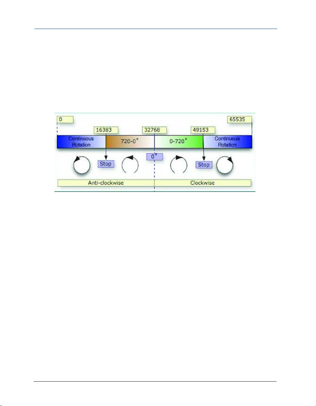
CHAPTER 7
Movement and Size
The layer’s image can be rotated on each axis by adjusting the DMX value of the
appropriate X, Y, and Z Rotation parameters. The suggested default value for each
channel is the midpoint of the parameter’s 16-bit DMX range, which is equal to no
rotation. Increasing the DMX value from the midpoint indexes the image clockwise; as
reducing the DMX value below the midpoint, indexes the image counterclockwise.
X, Y, and Z Rotation parameter DMX values greater than the 720° limit in either direction,
will start the image rotating continuously. Further adjustments to the DMX values will
increase the speed of continuous rotation
.
48 Catalyst® V3 Media Server User Manual
Page 65

CHAPTER 7
Movement and Size
X Position
The X Position parameter adjusts the layer’s image horizontally along the X-axis. The
midpoint of the 16-bit DMX value range centers the image on the X-axis.
X Position parameter DMX values below the DMX midpoint move the image left, and
values above the DMX midpoint move the image right.
Image with an X Position value
at the DMX midpoint
Image with an X Position value
less than the DMX midpoint
Catalyst® V3 Media Server User Manual
Image with an X Position value
greater than the DMX midpoint
49
Page 66

CHAPTER 7
Movement and Size
Y Position
The Y Position parameter adjusts the layer’s image vertically along the Y-axis. The
midpoint of the 16-bit DMX value range, centers the image on the Y-axis.
Y Position parameter DMX values below the DMX midpoint move the image down, and
values above the DMX midpoint move the image up.
Image with a Y Position value
at the DMX midpoint
Image with a Y Position value
less than the DMX midpoint
Image with a Y Position value
greater than the DMX midpoint
50 Catalyst® V3 Media Server User Manual
Page 67

CHAPTER 7
Movement and Size
Scale
The Scale parameter
adjusts th
the layer’s image
up to 8x its original
size. When the
midpoint of the
16-bit DMX value
range equals 0x, the
image shrinks to invisibility). When the DMX value is increased from the midpoint, the
image is enlarged. In addition, when the DMX value is reduced below the midpoint, an
inverted image is enlarged.
e size of
Image with the suggested
default DMX value
Image with a value
greater than the DMX midpoint
Catalyst® V3 Media Server User Manual
Image with a value
less than the DMX midpoint
Image with a value
near the DMX midpoint
51
Page 68

CHAPTER 7
Movement and Size
Image Movement Time
The Movement Speed parameter
provides smoothing of
created with the Catalyst application.
Sometimes the transmission speed of
DMX-512 can result in choppy image
movements during slow Layer position
movements.
The Movement Speed parameter
provides a variable smoothing of
movements with DMX values from 0255—the higher the DMX value, the
slower the movement speed. Settings of
the Movement Speed parameter affect
changes to the X and Y Position, X, Y,
and Z Rotation, and Scale parameters.
movements
The red arrow indicates movement with the
X Position parameter.
52 Catalyst® V3 Media Server User Manual
Page 69

CHAPTER 7
Movement and Size
Aspect Ratio
The Aspect Ratio parameter allows horizontal or vertical image compression from full
image size to a thin line (1-4 pixels). The Aspect Ratio function compensates for dissimilar
aspect ratios encountered in various video formats. For example, a movie created with a
16:9 aspect ratio can be changed to a 4:3 aspect ratio. DMX values from 0 to 128 squeeze
the image horizontally, and DMX values greater than 128 compress the image vertically.
Image with a value
less than the DMX midpoint
Catalyst® V3 Media Server User Manual
Image with the midpoint DMX
value default
Image with a value
greater than the DMX midpoint
53
Page 70

CHAPTER 7
Movement and Size
54 Catalyst® V3 Media Server User Manual
Page 71

Chapter 8:
Intensity and Color
Intensity
The Intensity parameter adjusts layer brightness levels from black (DMX = 0) to full
intensity (DMX = 255). By crossfading the Intensity parameter of layers, a dissolve
between layers can be created.
Layer 1 with full Intensity Layer 2 with full Intensity
Layer 1 with full Intensity
and Layer 2 with Intensity set at the
DMX midpoint value
Catalyst® V3 Media Server User Manual 55
Page 72

CHAPTER 8
Intensity and Color
Red, Green, and Blue
The Catalyst Media Server uses an additive RGB color mixing system that modifies image
color by filtering specific percentages of red, green, and blue. With the Red, Green, and
Blue parameter DMX channels, a DMX value of 0 filters out all of a color, and a value of
255 filters none of it. If each channel’s DMX value is set to 0, all color is filtered out and
the result is black. With a DMX value of 255 in each channel, no color is filtered, which
means the image has no color adjustment. Some settings of the Color Effects parameter
change the functionality of the Red, Green, and Blue parameters.
Red parameter = 255
Green parameter = 255
Blue parameter = 255
Red parameter = 0
Green parameter = 255
Blue parameter = 255
56 Catalyst® V3 Media Server User Manual
Red parameter = 255
Green parameter = 0
Blue parameter = 0
Red parameter = 0
Green parameter = 0
Blue parameter =255
Page 73

CHAPTER 8
Intensity and Color
Color Effects
The Color Effects parameter alters a layer’s content by applying variations to the image’s
colors. In addition, some Color Effects change the behavior of the Red, Green, and Blue
parameters. This chapter describes the Color Effects and their capabilities.
0 RGB Subtract
When the Color Effects parameter is assigned a DMX value of 0, the Layer’s image can be
tinted. The Red, Green, and Blue parameters each remove existing color from the layer’s
image.
The Layer’s image without tinting The Layer’s image tinted with the
The Layer’s image tinted with the
Blue parameter.
Catalyst® V3 Media Server User Manual
Green, and Blue parameters.
The Layer’s image tinted with the
Red parameter.
57
Page 74

CHAPTER 8
Intensity and Color
1 RGB Subtract High Contrast
When the Color Effects parameter is assigned a DMX value of 1, the Layer’s image can be
tinted. This is a higher contrast version of the RGB Subtract Color Effect. The Red, Green,
and Blue parameters can remove existing color from the layer’s image.
The Layer’s original image
without a Color Effect.
The Layer’s image with the RGB
Subtract High Contrast Effect.
2 RGB Subtract V High Contrast
When the Color Effects parameter is assigned a DMX value of 2, the Layer’s image can be
tinted. This is a super high contrast version of the RGB Subtract Color Effect. The Red,
Green, and Blue parameters can remove existing color from the layer’s image.
The Layer’s original image
without a Color Effect.
The Layer’s image with the RGB Sub-
tract V High Contrast Effect.
58 Catalyst® V3 Media Server User Manual
Page 75

CHAPTER 8
Intensity and Color
3 Transparent Blacks
When the Color Effects parameter is assigned a DMX value of 3, any black in a Layer’s
image becomes transparent, revealing underlying Layers. The Red, Green, and Blue
parameters can remove existing color from the layer’s image.
Layer 1 Layer 2
Catalyst® V3 Media Server User Manual
Transparent Blacks applied to
Layer 2 reveals Layer 1 image.
59
Page 76

CHAPTER 8
Intensity and Color
4 Transparent Whites
When the Color Effects parameter is assigned a DMX value of 4, any white in a Layer’s
image becomes transparent, revealing underlying Layers. The Red, Green, and Blue
parameters can remove existing color from the layer’s image.
Layer 1 Layer 2
Transparent Whites applied to
Layer 2 reveals Layer 1 image.
60 Catalyst® V3 Media Server User Manual
Page 77

CHAPTER 8
Intensity and Color
10 RGB Subtract Inverted Color
When the Color Effects parameter is assigned a DMX value of 10, the colors in a Layer’s
image are inverted. The Red, Green, and Blue parameters can remove existing color from
the layer’s image.
The Layer’s original image
without a Color Effect.
The Layer’s image with the RGB
Subtract Inverted Color Effect.
11 RGB Subtract High Contrast Inverted Color
When the Color Effects parameter is assigned a DMX value of 11, the colors in a Layer’s
image are inverted. This is a higher contrast version of the RGB Subtract Inverted Color
Effect. The Red, Green, and Blue parameters can remove existing color from the layer’s
image.
The Layer’s original image
without a Color Effect.
The Layer’s image with the RGB
Subtract High Contrast Inverted Effect.
Catalyst® V3 Media Server User Manual
61
Page 78

CHAPTER 8
Intensity and Color
12 RGB Subtract Super High Contrast Inverted
Color
When the Color Effects parameter is assigned a DMX value of 12, the colors in a Layer’s
image are inverted. This is a super higher contrast version of the RGB Subtract Inverted
Color Effect. The Red, Green, and Blue parameters can remove existing color from the
layer’s image.
The Layer’s original image
without a Color Effect.
The Layer’s image with the
RGB Subtract Color Effect.
13 Invert Whatever
When the Color Effects parameter is assigned a DMX value of 13, the colors in a Layer’s
image are inverted. This Color Effect is a unique combination of transparency and color
modification. The Red, Green, and Blue parameters can remove existing color from the
layer’s image.
The Layer’s original image
without a Color Effect.
The Layer’s image with the
Invert Whatever Color Effect.
62 Catalyst® V3 Media Server User Manual
Page 79

CHAPTER 8
Intensity and Color
14 RGB Subtract Inverted Color CMY
When the Color Effects parameter is assigned a DMX value of 10, the colors in a Layer’s
image are inverted and converted to CMY. The Red, Green, and Blue parameters can
remove existing color from the layer’s image.
The Layer’s original image
without a Color Effect.
The Layer’s image with the RGB
Subtract Inverted Color CMY Effect.
15 RGB Subtract High Contrast Inverted Color CMY
When the Color Effects parameter is assigned a DMX value of 15, the colors in a Layer’s
image are inverted and converted to CMY. This is a higher contrast version of the RGB
Subtract Inverted Color CMY Effect. The Red, Green, and Blue parameters can remove
existing color from the layer’s image.
The Layer’s original image
without a Color Effect.
The Layer’s image with the RGB
Subtract High Contrast Inverted
CMY Effect.
Catalyst® V3 Media Server User Manual
63
Page 80

CHAPTER 8
Intensity and Color
16 RGB Subtract Super High Contrast Inverted
Color CMY
When the Color Effects parameter is assigned a DMX value of 16, the colors in a Layer’s
image are inverted and converted to CMY. This is the highest contrast version of the RGB
Subtract Inverted Color CMY Effect. The Red, Green, and Blue parameters can remove
existing color from the layer’s image.
The Layer’s original image
without a Color Effect.
The Layer’s image with the
RGB Subtract Super High Contrast
Inverted CMY Effect.
20 Black and White
When the Color Effects parameter is assigned a DMX value of 20, the Layer’s image
becomes black and white and can not be tinted. The Red, Green, and Blue parameters do
not function with this Color Effect.
The Layer’s original image
without a Color Effect.
The Layer’s image with the
Black and White Effect.
64 Catalyst® V3 Media Server User Manual
Page 81

CHAPTER 8
Intensity and Color
21 Black and White High Contrast
When the Color Effects parameter is assigned a DMX value of 21, the Layer’s image
becomes black and white and can not be tinted. This high contrast version of the Black
and White Color Effect is transparent, revealing underlying layers. The Red, Green, and
Blue parameters do not function with this Color Effect.
The Layer’s original image
without a Color Effect.
The Layer’s image with the Black and
White High Contrast Effect.
22 Black and White Super High Contrast
When the Color Effects parameter is assigned a DMX value of 22, the Layer’s image
becomes black and white and can not be tinted. This super high contrast version of the
Black and White Color Effect is transparent, revealing underlying layers. The Red, Green,
and Blue parameters do not function with this Color Effect.
The Layer’s original image
without a Color Effect.
The Layer’s image with the Black and
White Super High Contrast Effect.
Catalyst® V3 Media Server User Manual
65
Page 82

CHAPTER 8
Intensity and Color
23 Black and White Variable Super High Contrast
When the Color Effects parameter is assigned a DMX value of 23, the Layer’s image
becomes black and white and can not be tinted. This super high contrast version of the
Black and White Color Effect is transparent, revealing underlying layers. The Red, Green,
and Blue parameters each adjust the amount of the related color making up the final
value of the black and white image.
The Layer’s original image
without a Color Effect.
The Layer’s image with the Black
and White Variable Super
High Contrast Effect.
24 Invert Black and White
When the Color Effects parameter is assigned a DMX value of 24, the Layer’s image
becomes black and white and can not be tinted. This is an inverted version of the Black
and White Color Effect. The Red, Green, and Blue parameters do not function with this
Color Effect.
The Layer’s original image
without a Color Effect.
The Layer’s image with the Invert Black
and White Effect.
66 Catalyst® V3 Media Server User Manual
Page 83

CHAPTER 8
Intensity and Color
30 Mask
When the Color Effects parameter is assigned a DMX value of 30, the Layer’s image
becomes black and white and can not be tinted. Any black in a Layer’s image becomes
transparent, revealing underlying Layers. The Red parameter adjusts the Layer’s
percentage of transparency to vary mask softness. The Green, and Blue parameters do
not function with this Color Effect.
The Layer’s original image
without a Color Effect.
The Layer’s image with the
Mask Effect.
31 Invert Mask 1
When the Color Effects parameter is assigned a DMX value of 31, the Layer’s image
becomes black and white and can not be tinted. Any black in a Layer’s image becomes
transparent, revealing underlying Layers. White areas within the Layer’s image become
black. The Red parameter adjusts the Layer’s percentage of transparency to vary mask
softness. The Green, and Blue parameters do not function with this Color Effect.
The Layer’s original image
without a Color Effect.
The Layer’s image with the
Invert Mask 1 Effect.
Catalyst® V3 Media Server User Manual
67
Page 84

CHAPTER 8
Intensity and Color
32 Invert Mask 2
When the Color Effects parameter is assigned a DMX value of 32, the Layer’s image
becomes black and white and can not be tinted. Any white in a Layer’s image becomes
transparent, revealing underlying Layers. The Red parameter adjusts the Layer’s
percentage of transparency to vary mask softness. The Green, and Blue parameters do
not function with this Color Effect.
The Layer’s original image
without a Color Effect.
The Layer’s image with the
Invert Mask 2 Effect.
35 Mask Fading
A DMX Color Effects parameter value of 35 operates the same as a DMX value of 30 with
the addition of fading. The Layer’s image becomes black and white and can not be tinted.
Any black in a Layer’s image becomes transparent, revealing underlying Layers. The Red
parameter adjusts the mask percentage to vary mask softness. Green, and Blue parame-
ters do not function with this Color Effect. The intensity channel adjusts mask fading.
36 Invert Mask 1 Fading
A DMX Color Effects parameter value of 36 operates the same as a DMX value of 31 with
the addition of fading. The Layer’s image becomes black and white and can not be tinted.
Any black in a Layer’s image becomes transparent, revealing underlying Layers. White
areas within the Layer’s image become black. The Red parameter adjusts the mask
percentage to vary mask softness. The Green, and Blue parameters do not function with
this Color Effect. The intensity channel adjusts mask fading.
37 Invert Mask 2 Fading
A DMX Color Effects parameter value of 37 operates the same as a DMX value of 32 with
the addition of fading. The Layer’s image becomes black and white and can not be tinted.
Any white in a Layer’s image becomes transparent, revealing underlying Layers. The Red
parameter adjusts the mask percent to vary the softness. The Green, and Blue parameters
do not function with this Color Effect. The intensity channel adjusts mask fading.
68 Catalyst® V3 Media Server User Manual
Page 85

CHAPTER 8
Intensity and Color
40 Alpha Invert as Red
When the Color Effects parameter is assigned a DMX value of 40, the portions of a
Layer’s image without an alpha channel become red and can not be tinted. Any alpha
channel portions of the image become transparent, revealing underlying Layers. The Red,
Green, and Blue parameters do not function with this Color Effect.
The Layer’s original image
without a Color Effect.
Note: An alpha channel is embedded into content when the media file is created.
The Layer’s image with an
Alpha Invert as Red Effect.
41 Alpha Invert as Green
When the Color Effects parameter is assigned a DMX value of 41, the portions of a
Layer’s image without an alpha channel become green and can not be tinted. Any alpha
channel portions of the image become transparent, revealing underlying Layers. The Red,
Green, and Blue parameters do not function with this Color Effect.
The Layer’s original image
without a Color Effect.
Note: An alpha channel is embedded into content when the media file is created.
The Layer’s image with an
Alpha Invert as Green Effect.
Catalyst® V3 Media Server User Manual
69
Page 86

CHAPTER 8
N
Intensity and Color
42 Alpha Invert as Blue
When the Color Effects parameter is assigned a DMX value of 42, the portions of a
Layer’s image without an alpha channel become blue and can not be tinted. Any alpha
channel portions of the image become transparent, revealing underlying Layers. The Red,
Green, and Blue parameters do not function with this Color Effect.
The Layer’s original image
without a Color Effect.
ote: An alpha channel is embedded into content when the media file is created.
The Layer’s image with an
Alpha Invert as Blue Effect.
43 Alpha Invert as Color
When the Color Effects parameter is assigned a DMX value of 43, the portions of a
Layer’s image without an alpha channel become white and can be tinted. Any alpha
channel portions of the image become transparent, revealing underlying Layers. The Red,
Green, and Blue parameters are used to select an alpha channel color.
The Layer’s original image
without a Color Effect.
Note: An alpha channel is embedded into content when the media file is created.
The Layer’s image with an
Alpha Invert as Color Effect.
70 Catalyst® V3 Media Server User Manual
Page 87

CHAPTER 8
Intensity and Color
44 Alpha as Red
When the Color Effects parameter is assigned a DMX value of 44, the portions of a
Layer’s image with an alpha channel become red and can not be tinted. Non alpha
channel portions of the image become transparent, revealing underlying Layers. The Red,
Green, and Blue parameters do not function with this Color Effect.
The Layer’s original image
without a Color Effect.
Note: An alpha channel is embedded into content when the media file is created.
The Layer’s image with
Alpha as Red Effect.
45 Alpha as Green
When the Color Effects parameter is assigned a DMX value of 45, the portions of a
Layer’s image with an alpha channel become green and can not be tinted. Non alpha
channel portions of the image become transparent, revealing underlying Layers. The Red,
Green, and Blue parameters do not function with this Color Effect.
The Layer’s original image
without a Color Effect.
The Layer’s image with
Alpha as Green Effect.
Note: An alpha channel is embedded into content when the media file is created.
Catalyst® V3 Media Server User Manual
71
Page 88

CHAPTER 8
Intensity and Color
46 Alpha as Blue
When the Color Effects parameter is assigned a DMX value of 46, the portions of a
Layer’s image with an alpha channel become blue and can not be tinted. Non alpha
channel portions of the image become transparent, revealing underlying Layers. The Red,
Green, and Blue parameters do not function with this Color Effect.
The Layer’s original image
without a Color Effect.
Note: An alpha channel is embedded into content when the media file is created.
The Layer’s image with
Alpha as Blue Effect.
47 Alpha as Color
When the Color Effects parameter is assigned a DMX value of 47, the portions of a
Layer’s image with an alpha channel become white and can be tinted. Non alpha channel
portions of the image become transparent, revealing underlying Layers. The Red, Green,
and Blue parameters are used to select an alpha channel color.
The Layer’s original image
without a Color Effect.
Note: An alpha channel is embedded into content when the media file is created.
The Layer’s tinted image
with an Alpha as Color Effect.
72 Catalyst® V3 Media Server User Manual
Page 89

CHAPTER 8
Intensity and Color
50 Lookup 1 Color Wheel
When the Color Effects parameter is assigned a DMX value of 50, a color-wheel based
formula is applied to the Layer’s image colors. This effect does not allow tinting. The Red,
Green, and Blue parameters do not function with this Color Effect.
Original image.
Image with the
Invert Lookup 1 Color Effect.
51 Lookup 2 False Color
When the Color Effects parameter is assigned a DMX value of 51, the Layer’s image
becomes mutated can not be tinted. The Red, Green, and Blue parameters do not function
with this Color Effect.
The Layer’s original image
without a Color Effect.
The Layer’s image with the
Invert Lookup 2 Effect.
Catalyst® V3 Media Server User Manual
73
Page 90

CHAPTER 8
Intensity and Color
52 Lookup 3 Black and White Solarize Highlights
When the Color Effects parameter is assigned a DMX value of 52, the Layer’s image
becomes magenta and can not be tinted. The Red, Green, and Blue parameters do not
function with this Color Effect.
The Layer’s original image
without a Color Effect.
The Layer’s image with the
Lookup 3 Effect.
60 Gamma Black and White
When the Color Effects parameter is assigned a DMX value of 60, the Layer’s image
becomes black and white and can not be tinted. The Red parameter adjusts the contrast of
the image. The Green, and Blue parameters do not function with this Color Effect.
The Layer’s original image
without a Color Effect.
The Layer’s image with the
Gamma Black and White Effect.
74 Catalyst® V3 Media Server User Manual
Page 91

CHAPTER 8
Intensity and Color
61 Gamma Color
When the Color Effects parameter is assigned a DMX value of 61, the Layer’s image
becomes red and can not be tinted. The Red parameter adjusts the overall gamma of the
image. The Green, and Blue parameters do not function with this Color Effect.
The Layer’s original image
without a Color Effect.
The Layer’s image with the
Gamma Color adjustment.
The Layer’s image with the
Gamma Color Effect applied.
Catalyst® V3 Media Server User Manual
75
Page 92

CHAPTER 8
Intensity and Color
62 Gamma Color Separate Channels
When the Color Effects parameter is assigned a DMX value of 62, the Layer’s image is
displayed with high contrast. The Red, Green, and Blue parameters adjust the
corresponding color gamma of the image.
The Layer’s original image
without a Color Effect.
The Layer’s image with the Gamma Color
Separate Effect Green channel adjustment.
The Layer’s image with the
Gamma Color Separate Effect.
76 Catalyst® V3 Media Server User Manual
Page 93

CHAPTER 8
Intensity and Color
63 Gain Color Separate Channels
When the Color Effects parameter is assigned a DMX value of 62, the Layer’s image is
displayed with high contrast. The Red, Green, and Blue parameters adjust the
corresponding color gain of the image.
The Layer’s original image
without a Color Effect.
The Layer’s image with the Gain Color Separate
Channels Effect and Blue channel adjustment.
The Layer’s image with the
Gain Color Separate Channels Effect.
Catalyst® V3 Media Server User Manual
77
Page 94

CHAPTER 8
Intensity and Color
65 Quantize Color Separate Channels
When the Color Effects parameter is assigned a DMX value of 65, the Layer’s image is
displayed with a reduced set of representative colors. The Red, Green, and Blue
parameters adjust the corresponding color in the image.
The Layer’s original image
without a Color Effect.
The Layer’s image with the Quantize Color Separate
Channels Effect and Red channel adjustment.
The Layer’s image with the
Quantize Color Separate Channels Effect.
78 Catalyst® V3 Media Server User Manual
Page 95

CHAPTER 8
Intensity and Color
70 Convert to YUV
When the Color Effects parameter is assigned a DMX value of 70, the Layer’s image RGB
color information is converted to a different color space. The Red parameter adjusts the
illuminance of the image. The Green parameter adjusts the U component and the Blue
parameter adjusts the V component.
The Layer’s original image
without a Color Effect.
The Layer’s image with the
Convert to YUV Effect.
71 Saturation
When the Color Effects parameter is assigned a DMX value of 71, the Layer’s image can
not be tinted. The Red parameter reduces the color saturation of the image. When the Red
parameter is set to 0, the image is black and white. The Green, and Blue parameters do
not function with this Color Effect.
The Layer’s original image
without a Color Effect.
The Layer’s image with a
50% Saturation Effect.
Catalyst® V3 Media Server User Manual
79
Page 96

CHAPTER 8
Intensity and Color
72 Mega Saturation
When the Color Effects parameter is assigned a DMX value of 72, the Layer’s image can
not be tinted. The Red parameter adds and subtracts from the color saturation of the
image. With no color saturation the image is black and white. The Green, and Blue
parameters do not function with this Color Effect.
The Layer’s original image
without a Color Effect.
The Layer’s image with a Mega
Saturation Effect.
73 Solarize
When the Color Effects parameter is assigned a DMX value of 73, the Layer’s image
becomes solarized and can not be tinted. The Red, Green, and Blue parameters do not
function with this Color Effect.
The Layer’s original image
without a Color Effect.
The Layer’s image with the
Solarize Effect.
80 Catalyst® V3 Media Server User Manual
Page 97

CHAPTER 8
Intensity and Color
74 Solarize Invert
When the Color Effects parameter is assigned a DMX value of 74, the Layer’s colors are
inverted, the image becomes solarized, and it can not be tinted. The Red, Green, and Blue
parameters do not function with this Color Effect.
The Layer’s original image
without a Color Effect.
The Layer’s image with the
Solarize Invert Effect.
80 RGB Layer Blend 1
When the Color Effects parameter is assigned a DMX value of 80, the white portions of
the Layer’s image become transparent and the image can be tinted. The Red, Green, and
Blue parameters each remove existing color from the layer’s image.
The Layer’s original image
without a Color Effect.
The Layer’s image with the
RGB Layer Blend 1 Effect.
Catalyst® V3 Media Server User Manual
81
Page 98

CHAPTER 8
Intensity and Color
81 RGB Layer Blend 2
When the Color Effects parameter is assigned a DMX value of 81, the black portions of
the Layer’s image become transparent and the image can be tinted. The Red, Green, and
Blue parameters can remove existing color from the layer’s image.
The Layer’s original image
without a Color Effect.
The Layer’s image with the
RGB Layer Blend 2 Effect.
82 RGB Layer Blend 3
When the Color Effects parameter is assigned a DMX value of 82, the white portions of
the Layer’s image become semi-transparent and the image can be tinted. The Red, Green,
and Blue parameters each remove existing color from the layer’s image.
The Layer’s original image
without a Color Effect.
The Layer’s image with the
RGB Layer Blend 3 Effect.
82 Catalyst® V3 Media Server User Manual
Page 99

CHAPTER 8
Intensity and Color
83 RGB Layer Blend 4
When the Color Effects parameter is assigned a DMX value of 83, portions of the Layer’s
image become transparent and the image can be tinted. The Red, Green, and Blue
parameters each remove existing color from the layer’s image.
The Layer’s original image
without a Color Effect.
The Layer’s image with the
RGB Layer Blend 4 Effect.
84 RGB Layer Blend 5
When the Color Effects parameter is assigned a DMX value of 84, portions of the Layer’s
image become semi-transparent and the image can be tinted. The Red, Green, and Blue
parameters each remove existing color from the layer’s image.
The Layer’s original image
without a Color Effect.
The Layer’s image with the
RGB Layer Blend 5 Effect.
Catalyst® V3 Media Server User Manual
83
Page 100

CHAPTER 8
Intensity and Color
85 RGB Layer Blend 6 Add
When the Color Effects parameter is assigned a DMX value of 85, black portions of the
Layer’s image become transparent and the image can be tinted. The Red, Green, and Blue
parameters each remove existing color from the layer’s image.
The Layer’s original image
without a Color Effect.
The Layer’s image with the
RGB Layer Blend 6 Effect.
86 RGB Layer Blend 7 Subtract
When the Color Effects parameter is assigned a DMX value of 86, white portions of the
Layer’s image become semi-transparent and the image can be tinted. The Red, Green,
and Blue parameters each remove existing color from the layer’s image.
The Layer’s original image
without a Color Effect.
The Layer’s image with the
RGB Layer Blend 7 Effect.
84 Catalyst® V3 Media Server User Manual
 Loading...