

Page 1

User Manual
High End Systems, Inc.
2217 West Braker Lane
Austin, TX 78758 U.S.A.
P/N 60600034 Version 4.1
Page 2

Page 3

User Manual
© High End Systems, Inc. 1997, All Rights Reserved
Information and Specifications in this document are subject to change
without notice. High End Systems, Inc. assumes no responsibility or
liability for any e rrors or inaccuracies that may appear in this manual.
The system software for the Status Cue® lighting console described in
this manual is furnished under a lice nse agreement a nd may be use d or
copied only in accordance with the terms of the agreement.
Trackspot User M anual
P/N 60600034 Version 4.1
September 02, 1999
Printed in the U.S. A.
C.C.
Trackspot User Manua l
i
Page 4

International Sales
U.S. and the
Americas:
Europe:
Singapore:
World Wide Web:
High End Systems, Inc. or High End Systems, Inc.
2217 West Braker Lane 8200 Haskell Avenue
Austin, TX 7875 8 Van Nuys, CA 91406
USA USA
voice: (512) 836-2242 voice: (818) 947-0550
FAX: (512) 837-5290 FAX: (818) 908-8975
High End Systems GmbH
Lohstrasse 22
D-85445 Schwaig
Germany
voice: +49 8122 9903-0
FAX: +49 8122 9903 - 33
High End Systems Singapore Pte. Ltd.
1 Tannery Road 06-05
Cencon 1
Singapore 1334
voice: +65 742 8266
FAX: +65 743 9322
http://www.highend.com
Trademarks
Trademarks used in t his t ext: Lightwave Research and High End
Systems are registered trademarks; Trackspot, Status Cue, and
Intellabeam are trademarks of High End Systems, Inc.
Belden is a registered trademark of Beld en, Inc . Ph ilips is a re gistered
trademark of Philips Lighting C ompany. Other trademarks and trade
names may be used in this document to refer to either the entities
claiming the marks and names or their products. High End System s
disclaims any proprietary i nterest in trademarks and trade names
owned by others.
Patents
Trackspo t may use one or more of the following paten ts: US 4,962, 687;
US 5,078,039; UK 2,043 ,769; US 5,331,8 22; US 5,40 2,326; US D372550 ;
UK 2292896; US D365165; US 5,430,629; US D360,404; US 5,455, 748;
0475082; US 5, 506,762; M9604 224.9; US 5,515,254; US D370080; UK
2.291,814; US 5,545.951; UK 2055842; UK 2,292,530; UK 2294909 ; UK
2292896; MR 8621996; and US 5,580, 164.
Additio n al pa t ents pendin g .
ii
Trackspot User Manual
Page 5

Declaration of Conformity
according to ISO/IEC Guide 22 and EN45104
Manufacturer ’ s na me :
Manufacturer’s address:
Distributor’s name:
Distributor’s address:
Declares that the product
Product Name:
Product Num ber:
Product Options:
Lightwave Research
2217 West Braker Lane
Austin, Texas 78758
U.S.A.
High End Systems, Inc.
2217 West Braker Lane
Austin, Texas 78758
U.S.A.
Trackspot
Trackspot
All
conforms to the following EEC directives:
73/23/EEC, as amended by 93/68/EEC
89/336/EEC, as amended by 92/31/EEC and 93/68/EEC
Equipment referred to in t his declaration of conformity was first
manufactured in compliance with the following standards in 1995:
Safety:
EMC:
EN 60598-1 : 1993
EN 60598-2-17 : 1989
A1-A3 : 1993
EN 55022, Class A I TE
IEC 801-2, 19 9 1 Level 2 (4/8 kV)
IEC 801-3, Dr a ft 5 Le vel 2 (3 V/m)
IEC 801-4, 1988 Level 2 (1 kV/0.5 kV)
U.S.A., September 02, 1999
Lanny Derryberry, Compliance Engineer
Trackspot User Manua l
iii
Page 6

Important Safety Information
Instructions pertaining to continued protection against fire, electric
shock, exposure to excessive ultraviolet (UV) radiation, and injury to
persons are found in Appendix D.
Please read all instructions prior to assembly, mounting, and operating
this equipment.
Important: Informations De Sécurité
Les instructions se rapportant à la protection permanente contre les
incendies, l’électrocution, l’exposition à un rayonnement ultraviolet
(UV) excessif et aux blessures cor porelles se trouve nt dans l’A nnexe D.
Veuillez lire toutes les instructions avant d’assembler, de monter ou
d’utiliser cet équipement.
Wichtige Sicherheitshinweise
Sicherheitsanleitungen zum Schutz gegen Feuer, elektrischen Schlag,
übermäßige UV-Strahlung und Verletzung von Personen finden Sie in
Anhang D.
Vor der Montage, dem Zusammenbau und der Inb etriebnahme dieses
Geräts alle Anleitungen sorgfältig durchlesen.
Informazioni Importanti Di Sicurezza
Le istruzioni sulla protezione da incendi, folgorazione, esposizione
eccessiva a raggi ultravioletti (UV) e infortuni sono contenute
nell’appendice D.
Si prega di leggere tutte le istruzioni prima di assemblare, montare e
azionare l’apparecchiatura.
Informacion Importante De Seguridad
En el Apéndice D se encuentran instrucciones sobre protección
continua contra incendios, descarga eléctrica, exposición excesiva a
radiación ultravioleta (UV) y lesion es pe rsonales.
Lea, por favor, todas las instrucciones antes del ensamblaje, montaje y
operación de este equipo.
Warranty Information
Limited Warranty
Unless otherwise stated, your product is covered by a two-year parts
and labor limited warranty. Dichroic filters are not guaranteed against
breakage or scratches to coating. It is the owner’s responsibility to
furnish receipts or invoices for verification of purchase, date, and
iv
Trackspot User Manual
Page 7

dealer or distributor. If purchase date cannot be provided, date of
manufacture will be used to determine warranty period.
Returning an Item Under Warranty for Repair
It is necessary to obtain a Return Material Authorization (RMA)
number from your dealer or point of purchase
returned for repair. The manufacturer will make the final
determination as to whether or not the unit is covered by warranty.
Lamps are covered by the lamp manufacturer’s warranty.
Any Product unit or parts returned to High End Systems must be
packaged in a suitable manner to en sure the protection of such Product
unit or parts, and such package shall be clearly and prominently
marked to indicate that the package contains returned Product units or
parts and with a Return Material Authorization number. Accompany
all returned Product units or parts with a written explanation of the
alleged problem or malfunction.
BEFORE
any units are
Please Note:
Freight Damage Claims are invalid for fixtures
shipped in non-factory boxes and packing materials.
Freight
All shipping will be paid by the purchaser. Items under warranty shall
have return shipping paid by the manufacturer only in the Continental
United States.
be accepted.
as air freight. Air freight can be sent customer collect in the
Continental United States.
REPAIR OR REPLACE MENT AS PROVIDED FOR UNDE R THIS
WARRANTY IS THE EXCLUSIVE REMEDY OF THE CONSUMER.
HIGH END SYSTEMS, INC. MAKES NO WARRANTIES, EXPRESS
OR IMPLIED, WITH RESPECT TO ANY PRODUCT, AND HIGH END
SPECIFICALLY DISCLAIMS ANY WARRANTY OF
MERCHANTABILITY OR FITNESS FOR A PARTICULAR PURPOSE.
HIGH END SHALL NOT BE LI ABLE FO R ANY INDIRECT,
INCIDENTAL OR CONS E Q UENTIAL DAMAGE, INCLUDING LOS T
PROFITS, SUSTAINED OR INCURRED IN CONNECTION WITH ANY
PRODUCT OR CAUSED BY PRODUCT DEFECTS OR THE PARTIAL
OR TOTAL FAILU RE OF AN Y PR ODUCT REGARDLESS OF TH E
FORM OF ACTI ON, WHETHER IN CONTRACT , TORT (INCLUD ING
NEGLIGENCE), STRICT LIABILITY OR OTHERWISE, AND
WHETHER OR NOT SUCH DAMAGE WAS FORESEEN OR
UNFORESEEN.
Under n o circumstances wi l l fr ei ght collect shipm e nts
Prepaid shipping does not include rush expediting such
Warranty is void for unauthorized repairs or parts or if the product is
misused, damaged, or modified in any way. This warranty gives you
specific legal rights, and you may also have other rights which vary
from state to state.
Trackspot User Manua l
v
Page 8

FCC Information
This equipment has been tested and found to comply with the limits for
a Class A digital device, pursuant to part 15 of the FCC rules. These
limits are designed to provide reasonable protection against harmful
interferenc e when the equipment i s ope r ated in a commerci al
environment. This equipment generates, uses, and can radiate radio
frequency energy and, if not installed and used in accordance with the
instruction manual, may cause harmful interference to radio
communications. Operation of this equipment in a residential area is
likely to cause harmful interference in which case the user will be
required to correct the interference at his own expense.
Product Modification Warning
High End Systems products are de signed and manufactured to meet
the requirements of United States and International safety regulations.
Modifications to the product could affect safety and render the product
non-compliant to relevant safety standards.
Mise En Garde Contre La Modification Du Produit
Les produits High End Systems sont conçus et fabriqués
conformément aux exigences des règlements internationaux de
sécurité. Toute modification du produit peut entraîner sa non
conformité aux normes de sécurité en vigueur.
Produktmodifikationswarnung
Design und Herstellung von High End Systemen entsprechen den
Anforderungen der U.S.A. und den internationalen
Sicherheitsvorschriften. Abänderungen dieses Produktes können
dessen Sicherheit beeinträchtigen und u. U. gegen die diesbezüglichen
Sicherheitsnormen verstoßen.
Avvertenza Sulla Modifica Del Prodotto
I prodotti di High End Systems sono stati progettati e fabbricati per
soddisfare i requisiti delle normative di sicurezza statunitensi ed
internazionali. Qualsiasi modifica al prodotto potrebbe pregiudicare la
sicurezza e rendere il prodotto non conforme agli stan dard di sicurezza
pertinenti.
Advertencia De Modificación Del Producto
Los productos de High End Systems están diseñados y fabricados para
cumplir los requisitos de las reglamentaciones de seguridad de los
Estados Unidos e internacionales. Las modificaciones al producto
podrían afectar la seguridad y dejar al producto fuera de conformidad
con las normas de seguridad relevantes.
vi
Trackspot User Manual
Page 9

Table of Contents
Introduction
Trackspot® Features ...................................................................... Intro-1
Caution and Warning Symbols ..................................................... Intro-2
Cautions .................................................................................. Intro-2
Warnings ................................................................................. Intro-2
Getting Help ................................................................................... Intro-3
Specificatio ns .................... .................... .................. .................... ...Intro-4
Model Information ............................ ................................ ......Intr o-4
Physical Specif i cati ons ....... ....................................................Intro-4
Electrical Specifications ......................................................... Intro-4
Environmental Specifications ................................................ Intro-5
Cable and Connector Specifications ..................................... Intro-5
DMX data cables ............................................................. Intro-5
DMX data connectors .....................................................Intro-5
DMX data terminators .................................................... Intro-5
Safety Specifications .............................................................. Intro-5
Optional Accessories .....................................................................Intro-6
Chapter 1 Setup and Assembly
Unpacking Trackspot® .............. ......... ........... ............ ........ ............ ...... 1-1
Saving the Shipping Mate ri al s . .................................................... 1-1
Inspecting the Contents ............................................................... 1-1
Installing the Yoke ............................................................................... 1-1
Selecting the Voltage .................... ....................................................... 1-3
Powering Up the Fixture .............. ................................ ....................... 1-3
Understanding LED Indicators ........................................................... 1-4
Fan LED ........................................................................................ 1-4
Enable LED ................ ... ............................................................. ... 1-4
Audio LED ..................................................................................... 1-4
Chapter 2 Configuring Your Trackspot
Choosing a Control Mode ................................................................... 2-1
DMX 512 Protocol ........................................................................ 2-1
LWR Protocol ................................................................................ 2-2
Standard Analog ........ .................. ................................................. 2-2
Stand Alone Operation (Master/Slave) ....................................... 2-2
Enabling the Control Mode .......... ................. ................................ ...... 2-3
Personality Switches .................................................................... 2-3
Address Switche s .......................................................................... 2-6
Installing Remote Enable/Disable ...................................................... 2-6
SPST Switch .................................................................................. 2-7
External Voltage Source .............................................................. 2-7
Mounting the Fixture .......... ................. ............................................... 2-8
®
Trackspot User Manua l
vii
Page 10

Additional Hardwar e ............................... ..................................... 2-8
Truss or Other Support System ............................................ 2-8
Safety Cable ........................................................................... 2-9
Clamp ..................................................................................... 2-9
Obtaining Cabling and Term i nat ors ... .............................................. 2-10
Constructing Cabling .................................... ............................. 2-11
Constructing Terminat or s .................. ............................... ......... 2-11
Linking the Fixtures ...................... .................................................... 2-12
DMX 512 Protocol ...................................................................... 2-12
LWR Protocol .............................................................................. 2-14
Standard Analog .... .............................................. ....................... 2 -15
Stand Alone Operation (Master/Slave) ..................................... 2-16
Focusing the Fixture .......................................................................... 2-17
Chapter 3 General Maintenance
Replacing Parts .................................................................................... 3-1
Replacing the Lamp ...................................................................... 3-1
Replacing Power Supp l y Fuse s ...... ............................................. 3-4
Replacing the Mirror Assembly ................................................... 3-6
Replacing or Installing Custom Gobos ....................................... 3-7
Cleaning Your Trackspot
Cleaning the Outer Surfa c es ..... ................................................... 3-9
Cleaning the Internal Comp one nt s .............. ... .......................... 3-10
Removing the Color Wheel or Gobo Wheel .............. ......... 3-10
Reinstalling the Color Wheel or Gobo Wheel .................... 3-12
Adjusting Wheel Clearance ............................................................... 3-12
®
............... ................. .................... .............. 3-9
Chapter 4 Troubleshooting
Fixture does not work: no LEDs, fans, lamp, or other
functionality (fixture appears dead) ................................................... 4-1
Lamp will not strike ........... ... ................................ ............................... 4-1
Light output is low, beam edge is very soft, images fuzzy ............... 4-1
Lamp shuts off ..................................... ................................................ 4-2
Error tone (two level beeping) after the fixture homes .................... 4-2
Yellow Enable LED or green Audio LED does not illuminate .......... 4-3
Fixture does not respond to data ........................................................ 4-3
Color wheel or gobo wheel is not centered in the beam or is in
the wrong position ............................................. ................................ .. 4-3
None of the motors work and the yellow Enable LED does not illuminate
4-4
Appendix A DMX Control of Trackspot
Start Channels and Construct Parameters ........................................A-1
Low Resolution Mode ....... ... .............................................. ...........A-1
High Resolution Mode ..................................................................A-1
®
viii
Trackspot User Manual
Page 11

Appendix B Trackspot® MSpeed Times
DMX 512 Protocol MSpeed Times .....................................................B-1
LWR Protocol MSpeed Times .............................................................B-5
Appendix C Personality and Address
Switch Setting s
Personality Switch Settings ................................................................C-1
Address Switch Se ttings ..... ............................................................. ...C-2
Appendix D Important Safety Information
English Version ........... .................. ................................ .......................D-1
Appendice D
IMPORTANTES INFO RMATIONS SUR LA SÉCURIT É ...... ... .........D-2
Anhang D
WICHTIGE HINWEISE FÜR IHRE SICHERHEIT ............................D-3
Apéndice D
INFORMACIÓN IMPORTANTE DE SEGURIDAD ...........................D-4
Appendice D
IMPORTANTI INFORMAZIONI PER LA SICUREZZA .. ..................D-5
VIGTIG FIKKER HEDS INFORMATION - DANMARK .....D-6
Glossary
List of Figures
Figure 1-1. Side view of Trackspot .................................................... 1-2
Figure 1-2. Inserting the yoke screws and T-handles ...................... 1-2
Figure 1-3. Trackspot rear panel ....................................................... 1-3
Figure 1-4. LED location on the rear panel ...................................... 1-4
Figure 2-1. Address and personality DIP switches .......................... 2-3
Figure 2-2. Connecting a remote enable/disable switch to the
master fixture .................................................................. 2-7
Figure 2-3. Attaching two C-clamps to the Trackspot yoke .......... 2-10
Figure 2-4. Attaching a safety cable to the mounted fixture ......... 2-10
Figure 2-5. XLR 3-pin connectors .................................................... 2-11
Figure 2-6. Data cable terminator ................................................... 2-11
Figure 2-7. Linking fixtures to a DMX 512 protocol controller .... 2-13
Figure 2-8. Linking fixtures to a LWR protocol controller ............ 2-14
Figure 2-9. Analog In connector ...................................................... 2-15
Figure 2-10. Linking fixtures to a standard analog controller ...... 2-15
Figure 2-11. Linking maste r and slave fi xtur e s toge ther ........... ... . 2-16
Figure 2-12. Lens tube adjustment .................................................. 2-17
Figure 3-1. Underside of Trackspot ................................................... 3-2
Trackspot User Manua l
ix
Page 12

Figure 3-2. Underside of Trackspot with access door removed ...... 3-2
Figure 3-3. Proper way to handle a QT 8500 lamp ........................... 3-3
Figure 3-4. Installing a new lamp ...................................................... 3-3
Figure 3-5. Fuse locations on the circuit board ................................ 3-5
Figure 3-6. Fuse housing location on the rear panel ........................ 3-5
Figure 3-7. Mirror assembly ............................................................. 3-6
Figure 3-8. Installing a new mirror ...................................................3-6
Figure 3-9. Custom gobo .................................................................... 3-7
Figure 3-10. Gobo wheel and gobo wheel sensor location .............. 3-8
Figure 3-11. Custom gobo aperture in gobo wheel .......................... 3-8
Figure 3-12. Trackspot internal components .................................. 3-10
Figure 3-13. Components of the color and gobo wheels ............... 3-11
Figure 3-14. Pull wheel up and out to remove ................................ 3-11
Figure 3-15. Sensor below each wheel ............................................ 3-11
Figure 3-16. Homing slot on wheel ................................................. 3-11
Figure 3-17. Allen screws on the color wheel and gobo wheel
hubs ............................................................................. 3-13
List of Tables
Table Intro-1. Trackspot optional accessories ............................ Intro-6
Table 2-1. Channel assignments ........................................................ 2-1
Table 2-2. Personality switch settings - operating modes ............... 2-3
Table 2-3. Personality switch settings - control modes .................... 2-5
Table 2-4. Address switch settings .................................................... 2-6
Table 3-1. Description and function of Trackspot fuses .................. 3-4
Table 4-1. Symptoms and Solutions .................................................. 4-1
Table A-1. Starting channels in 7-channel DMX 512 protocol ........A-2
Table A-2. Construct parameters in DMX 512 low resolution
mode .................................................................................A-4
Table A-3. Construct parameters in DMX 512 high resolution
mode .................................................................................A-5
Table B-1. DMX 512 protocol MSpeed times ...................................B-1
Table B-2. LWR protocol MSpeed times ...........................................B-5
Table C-1. Personality switch settings for all control modes and
operating modes ..............................................................C-1
Table C-2. Address switch settings for LWR protocol and
master/slave mode ...........................................................C-2
x
Trackspot User Manual
Page 13

Introduction
Congratulations on your purchase of the Trackspot® automated
luminaire. Trackspot is a versatile and affordable automated fixture
that outperforms any luminaire in its class. Superb engineering,
precision optics, and a variety of control options makes Track spot the
best value in low-cost intelligent lighting.
The Trackspot color wheel fe at ures e i ght richly-saturated dichroic
colors (plus white) and a color corrector. The 10-position gobo wheel
includes two multi-colored dichroic patterns and a replaceable custom
gobo position. Trackspot has an ultra-fast, smooth pan and tilt
capability as well as optical sensors that eliminate color or gobo
positioning errors. Control options include standard analog,
Lightwave Research (LWR) protocol, and DMX 512 protocol.
Trackspot is also fully functional with no controller at all (stand alone
mode).
Trackspot® Features
• Color wheel featuring eight dichroic colors plus color corrector
and open (white)
• Gobo wheel with eight unique patterns, including two multi-
colored dichroic patterns, and a replaceable custom gobo position
• Various control options, including stand alone operation, standard
analog, LWR protocol, and DMX 512 protocol
• Precision stepper motors for pan and tilt movement
• Optical sensor on color and gobo wheels to prevent positioning
errors
• External voltage switch with selectable voltage for 100V, 120V,
140V, 200V, 220V, or 240VAC at 50 or 60 Hz
• Thermal overload protection
• Multitap power transformer that provides over-voltage
compensations to help prevent surge-related problems
• QT 8500 lamp specifically des igned fo r us e with Trackspot
combining affordability, long lamp life (300 hour average),
reliability, high output, and stable color temperature throughout
the life of the lamp
• Electronic circuit design for 100% dimming
• Variable speed strobing
• 32 pre-programmed effects se que n ces
Trackspot User Manua l
Trackspot® Features
Intro-1
Page 14
• Built-in condenser microphone that picks up ambient bass to
trigger changes in the pre-programmed effects sequences
• Easy, quick lamp replacement with no optimization needed
• Remote system enable/disable using low voltage control
•Break-resistant mirror
• Pan and tilt invert option
• Low power co n s umption: 3.1 A @1 20V, 1.55 A @240V
• Complies with safety requirements in the USA, Canada, and the
European community.
Caution and Warning Symbols
The following international symbols appear in margins throughout this
manual to highlight caution and warning messages.
Cautions
Not heeding Caution messages could result in personal injury and/or
damage to equipment.
Caution: This symbol appears adjacent to Caution
messages.
Hot Surface: This symbol indicates a hot surface.
Warnings
Not heeding Warning messages could result in serious personal injury.
Warning: This symbol appears adjacent to high voltage
warning messages.
Fire Hazard: This symbol indicates that a fire hazard is
present.
Eye Protection: This symbol indicates that eye protection
1m
Intro-2
Minimum Distance: This symbol indicates the minimum
Caution and Warning Symbols
is required.
distance to a lighted object, which in
this case is 1 meter.
Trackspot User Manual
Page 15

Getting Help
Contact High End Systems Customer Service in one of the ways
shown:
U.S., the Americas,
and Europe:
Monday through Friday: (800) 890-8989
Singapore:
Service address:
High End Systems, Inc.
2227 West Braker Lane
Austin, TX 78758 USA
From 8 a.m. t o 6 p.m. (U.S. Central time)
24 hour FAX: (512) 834-9195
24 hour voice mail: (512) 837-3063
(800) 890-8989
or
Service address:
High End Systems, Inc.
8200 Haskell Avenue
Van Nuys, CA 91406 USA
From 8 a.m. to 5 p.m. (U.S . Pacific time)
Monday through Friday: (818) 947-0550
FAX: (818) 908-8975
High End Systems Singapore Pte. Ltd.
1 Tannery Road 06-05
Cencon 1
Singapore 1334
24-hour customer
service World W ide
Web response:
High End Systems
World Wide Web
site:
voice: +65 742 8266
FAX: +65 743 9322
http://info.highend.com/service/service.html
http://www.highend.com
Trackspot User Manua l
Getting Help
Intro-3
Page 16

Specifications
Model Information
Model: Trackspot
Manufacturer: Lightwave Research
2217 W. Braker Lane
Austin, TX 78758
USA
Distributor: High End Systems, Inc.
2217 W. Braker Lane
Austin, TX 78758
USA
Product Number: Trackspot
Physical Specifications
Dimensions (including yoke): 655mm L x 297mm W x 254mm H
(25.8” L x 11.7” W x 10” H)
Weight: 10.4 kg (23.0 lbs)
Lamp type: Philips® QT 8500, 250 W only
Electrical Specifications
Factory setting: 240 VAC
Voltage rating: 100V, 120V, 140V, 200V, 220V, 240V
Power consumption: 3.5 A @ 100V
2.9 A @ 120V
2.5 A @ 140V
1.75 A @ 200V
1.6 A @ 220V
1.5 A @ 240V
Rated pow er: 350W
Rated frequenc y : 50/60 Hz
Power facto r: 120V, 60 Hz: 0.98
240V, 50 Hz: 0.96
Maximum winding temperature, Tw: 130° C (266° F)
Maximum capacitor temperature, Tc: 85° C (185° F)
Warning: Class I equipment - For continued protection
Intro-4
Specifications
against electric shock connect this equipment
to an earthed (grounded) power source only.
Trackspot User Manual
Page 17
Environmental Specifications
Maximum ambient temperature, Ta: 50° C (122° F)
Maximum exteri o r sur fa c e tem pe r a t ur e: 67° C (153° F)
Minimum distance to lighted object: 1.0 meter (3.28 ft)
Minimum distance to flammable objects: 1.0 meter (3.28 ft)
Caution: Use in dr y locations only.
Warning: Do not mount on a flammable surface.
Cable and Connector Specifications
DMX data cables
Belden® 9841 or equivalent (meets specifications for EIA RS-485
applications) with the following characteristics:
• 2-conductor twisted pair plus a shield
• maximum capacitance between conductors - 30 pF/ft.
• maximum capacitance between conductor and shield - 55 pF/ft.
• maximum resistance of 20 / 1000 ft.
• nominal impedance 100-140
DMX data connectors
3-pin male and female XLR connectors
DMX data terminators
Male XLR connector with 120 ohm terminator
Safety Specificatio ns
Safety st an dards: EN 60598- 1 : 1993
EN 60598-2-17 : 1989
A1-A3 : 1993
EMC standards: EN 55022, Class A ITE
IEC 801-2, 1991 Level 2 (4/8 kV)
IEC 801-3, Dra ft 5 Level 2 (3 V/m)
IEC 801-4, 1988 Lev el 2 (1 kV/0.5 kV)
UL 153
CSA 22.2 No. 12
Trackspot User Manua l
Specifi ca tions
Intro-5
Page 18

Optional Accessories
T able 1-1 below lists the Trackspot optional accessories available from
your High End Systems dealer/distributor.
Table 1-1. Trackspot optional accessories
Part Descripti on Part Number
Status Cue Lighting Console 22020002
Intellabeam LCD Controller 01020006
Universal Controller 23020003
Trackspot Special Analog Controller 16020001
Modular Gobo wheel with tabs 99110017
Custom Gobo Call*
QT-8500 Trackspot replacement lamp 55030036
Keal road case, Trackspot (4 fixtures) 16070002
Keal road case, Trackspot (4 fixtures and 1
controller)
10' data cable, 3-pin XLR heavy duty 55050005
25' data cable, 3-pin XLR heavy duty 55050006
50' data cable, 3-pin XLR heavy duty 55050007
100' data cable, 3-pin XLR heavy duty 55050008
Galvanized safety cable with spring snap 12040001
Deluxe C-clamp with silver powdercoat finish 55000004
100' cable (for Trackspot Special Analog Controller
only)
50' cable (for Trackspot Special Analog Controller
only)
Interconnect cable extender 90409006
Unprogrammed RAM card for Intellabeam LCD or
Universal controller
Call* - For more information about optional accessories, contact either
your High End Systems dealer/distributor, High End System Sales, or
visit the High End Systems Web site. For contact information, see
“International Sales” on page ii.
16070001
07050001
07050002
80440017
Intro-6
Optional Accessories
Trackspot User Manual
Page 19

Chapter 1
Setup and Assembly
Unpacking Trackspot®
Unpack your fixture and verify that it arrived complete and wit hout
any damage.
Saving the Shipping Materials
Do not discard the shipping carton and packing materials. The carton
and packing materials are specifically designed to protect the product
during transport.
High End Systems assumes no responsibility for products that have
been damaged during transport. Therefore, you should return a
product for repair in its original shipp ing carton and p acking mate rials.
Note: Before sending anything to the factory, call your High End
Systems dealer/distributor for a Return Material
Authorization (RMA) number. The factory cannot accept
any goods shipped without an RA number.
1
Inspecting the Contents
Carefully unpack the carton and inspect the contents for damage. If
any of the items in the following list are missing or damaged, notify
both the shipping agent and your sales agent immediately.
•Trackspot fixture
®
• set of five Philips
• yoke (yoke screws and T-handles are already installed on the
fixture.)
QT 8500, 250 W lamps
Installing the Yoke
You will need:
• 1/4 inch allen wrench
• two 1/4 inch yoke screws*
• two clamping T-handles*
•yoke*
*These items are shipped with the Trackspot fixture.
Trackspot User Manua l
Unpacking Trackspot®
1-1
Page 20
To install the yoke:
1. Unplug the fixture. If the fixture has been operating, allow t h e
fixture to cool for at least 5 minutes.
2. Place the fixture on a sturdy surface so you can easily access both
sides of the fixture.
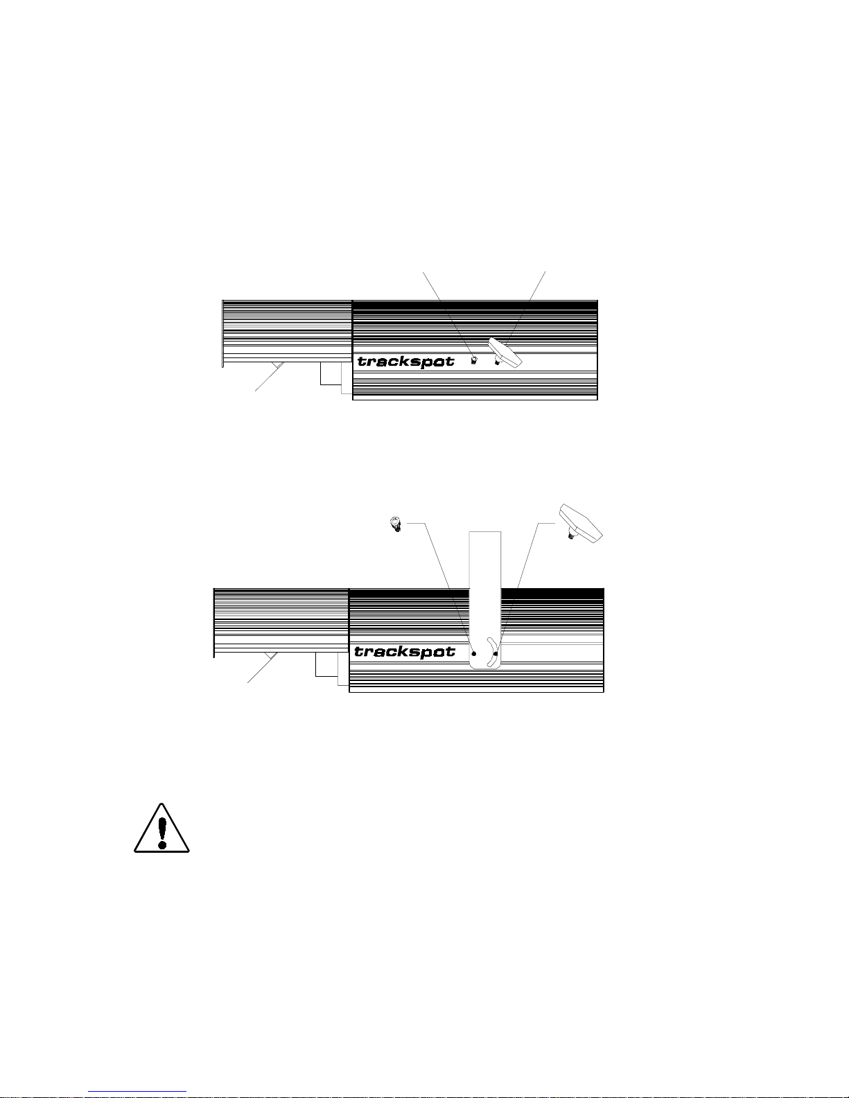
3. Remove the yoke screws and T-handles already installed in the
Trackspot fixture (see Figure 1-1).
yoke scr ew
T-handle
LIGHTWAVE RESE ARCH
AUSTIN, TX U.S.A.
Figure 1-1. Side view of Trackspot
4. Place the yoke ends over the fixture and align the yoke’s screw
holes with the screw holes on the fixture (see Figure 1-2).
LIGHTWAVE RESE ARCH
AUSTIN, TX U.S.A.
Figure 1-2. Inserting the yoke screws and T-handles
5. Replace the yoke screws through the round holes in each side of
the yoke an d t i ghten firm l y.
Caution: You must tighten the yoke screws firmly. The
6. Replace the T-handles through the semi-circular opening in each
side of the yoke. The T-handles should not be very tight; you will
adjust the T-handles when mounting the fixture.
On the top of the yoke are three 13 mm (1/2 inch) diameter mounting
holes used to mount the fixture. For more information, see the section
titled “Mounting the Fixture” on page 2-8.
1-2
Installing the Yoke
fixture may fall from the yoke if it is not
secured.
Trackspot User Manual
Page 21
Selecting the Voltage
Trackspot is factory set to 240 volts. If your power source is not 240
volts, you must change the fixture’s input voltage. Trackspot will
automatically adjust to the appropriat e fre q uency rat ing for any
voltage setting you select.
Warning: Be sure to match the fixture’s selectable
voltage to your power source prior to
operating this equipment.
You will need:
• wide tip, flat head screwdriver
To select the voltage:
1. Unplug the fixture.
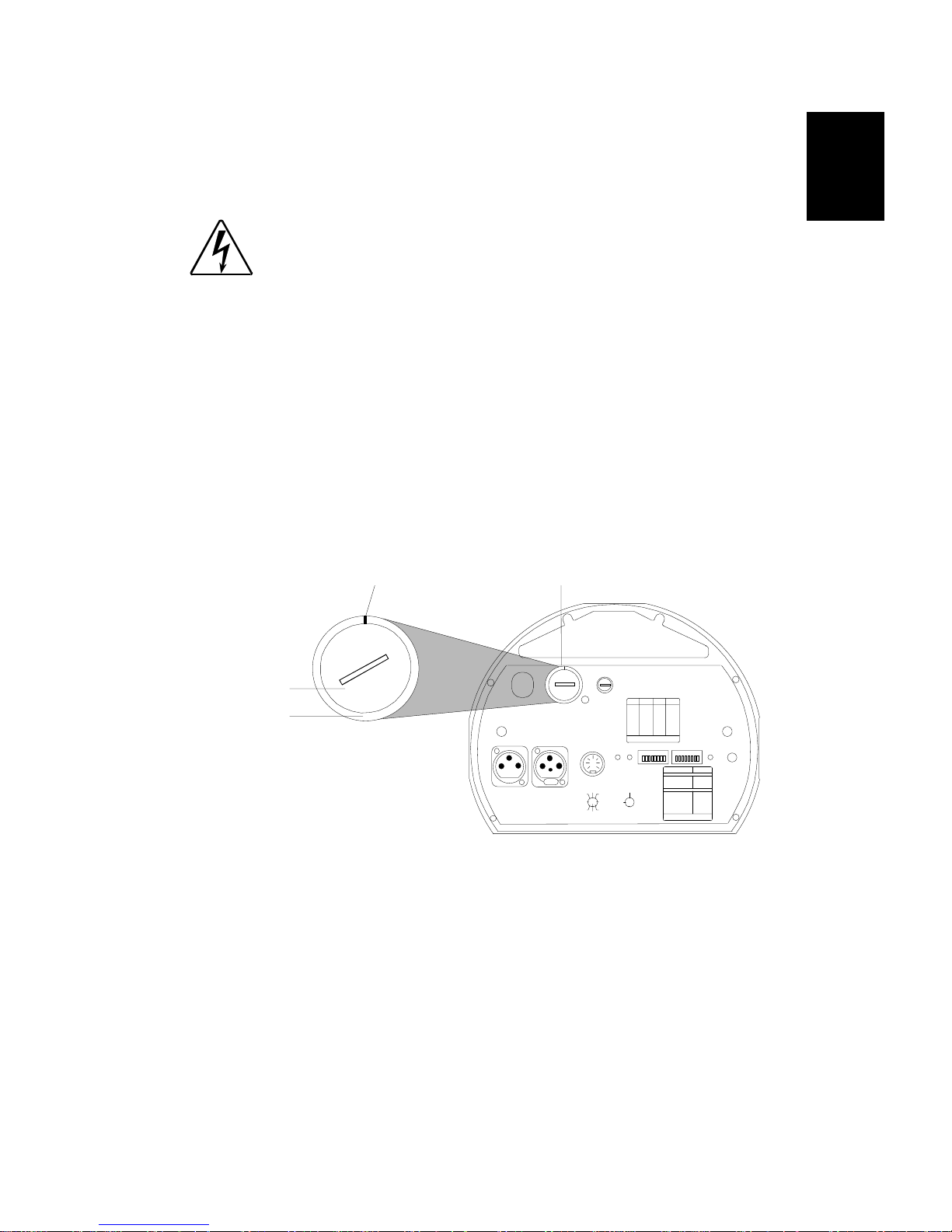
2. Insert a flat head screwdriver into th e slot on the v olta g e select
switch located on the rear panel of the fixture (see Figure 1-3).
3. Push the switch face in and turn until the line on the outer ring is
pointed at the voltage that is equal to the power source you are
using (see Figure 1-3).
1
switch face
outer ring
240 vo lt s sel e cted
100
240
120
200
140
220
voltage select switch
240
120
100
200
220
140
TILT
MSPEED
GOBO DIM
FUSE
ANALO G I N
0-10V
ANALOG
GND
COLO R
2
5
4
24 VDC
3761
OUT
PAN
8
(UNREG.)
FOR FUTHER INFORMATION
SHUTTER
CON SU L T US E R S M ANU AL
WARNING: CHANGE VOLTAGE SELECT ONLY WITH POWER REMOVED.
CAUTION: HOT REMOVE POWER BEFO RE REL AMPING
WARNING: NOT FO R RE SIDENTIAL USE. TO RE DUCE THE RI SK OF
FIRE OR ELEC TRIC SHOCK, DO NOT EXPOSE TO RAIN OR MOISTURE,
NO USER SERV ICE ABLE PART S INSID E. REFE R S ERVIC ING TO
QUALI FI ED SER VIC E PE R SO NN EL. FOR SAF E OP ERA TION CONS U LT
USER M A N UA L .
DATA I N
DATA O U T
VOLT AGE SELE CT
trackspot
LIGHTWAVE RESEARCH
2209 WEST BRAKER LANE, AUSTIN, TEXAS U.S.A.
SWITC HESONSWITC HESADDRE SS AD DRESS
ON
3,413
none01
1,3,414
102
2,3,415
203
1,2,3,416
1,204
517
305
1,518
1,306
2,519
2,307
1,2,520
1,2,308
3,521
409
1,3,522
1,410
2,3,523
2,411
1,2,3,524
1,2,412
FOR FURTHER INFORMATIO N
PLEASE CONSULT USER MANUAL
PERSONALITY
ADDRESS
ENABLEFAN
PERSONALITY SWITCHES
FIX TURE MODE SWIT CHES 1-2
NORMAL RUN
SELF T EST
SET-U P
SPECI AL AN A LOG
LAMP SAVE
INPUT
CONTROL MODE SWITCHES 3-8
GND
LIGHTWAVE CONTROL
DMX 1-256
DMX 257-512
2
4
5
ANALOG
1673
8
AUDI O (SLAV E)
AUDI O (MA ST ER )
PAN IN VERT
TILT INVERT
FOR FURTHER INFORMATIO N
PLEASE CONSULT USER MANUAL
®
MIC
AUDIO
ON
NON E
1
2
1,2
NON E
5
4
4,5
3
8
6
7
Figure 1-3. Trackspot rear panel
If the desired voltage is not listed on the voltage select switch,
choose the next higher v oltage. For example, if you have a 230 volt
power source, you must use the 240 volt setting.
4. After setting the correct voltage, make sure that the switch face is
flush with the outer ring (see Figure 1-3).
Powering Up the F ixture
Unlike other High End Systems lighting equipment, Trackspot does not
have a power switch. Powering up the fixture is as easy as plugging it
into a power source. However, it is very important that you unplug the
fixture before performing certain procedures as shown in this manual.
Trackspot User Manua l
Selecting the Voltage
1-3
Page 22
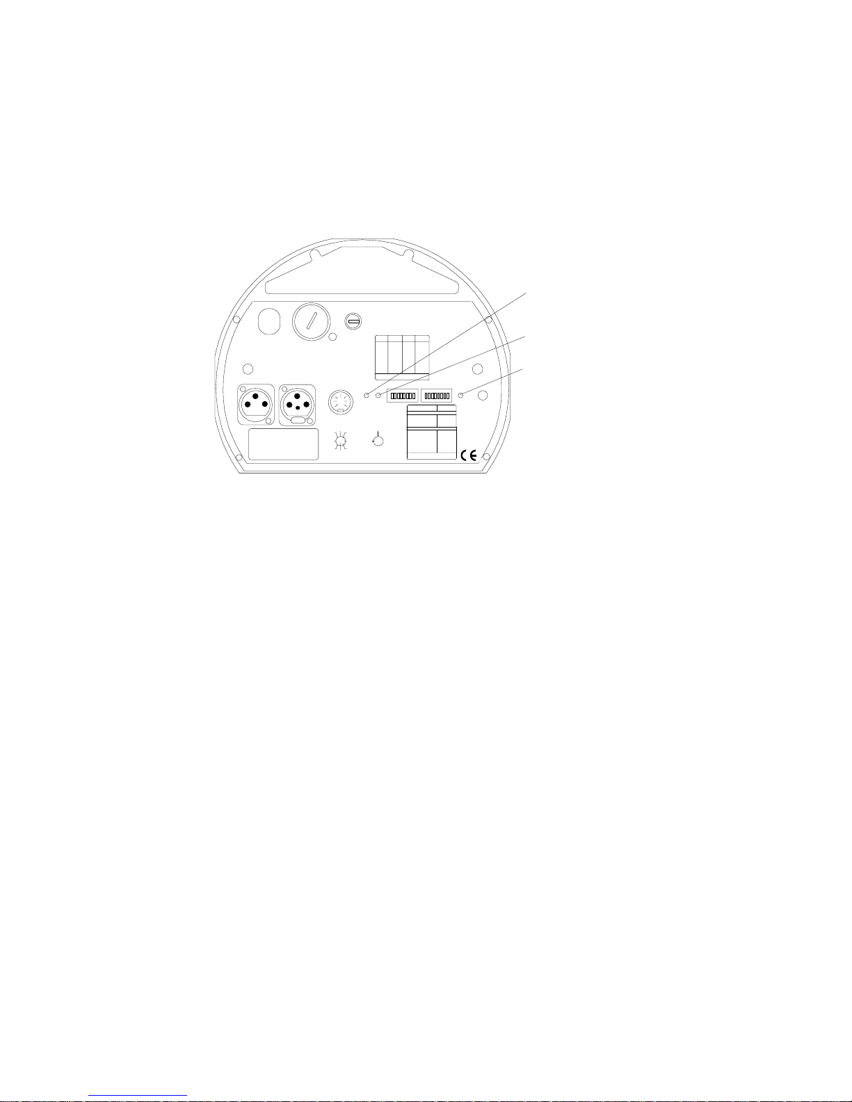
Understanding LED Indicators
This section describes the LEDs (Light Emitting Diode) on the
Trackspot rear panel: Fan, Enable, and Audio (see Figure 1-4). If you
are experiencing problems with your Trackspot fixture, these LEDs
may provide insight on where the problem is originating. See “” on
page 4-1 for possible solutions to LED-related symptoms.
Fan LED
200
140
VOLTAGE SELECT
WARNING: CHANGE VOLTAGE SELECT ONLY WI TH POWER REMOVED.
CAUTION: HOT REMOVE POWER BEFORE RELAMPING
WARNING: NOT FOR RESIDENTIAL USE. TO REDUCE THE RISK OF
FIRE O R ELECTRIC SHOCK, DO NOT EXPOSE TO RAIN OR MOISTURE,
NO USER SE RVI CEA B L E PARTS INSIDE. REFER SE RVI CING TO
QUALIFIED SERVICE PERSONNEL. FOR SAFE OPERATION CONSULT
USER MANUAL.
DATA OUTDATA IN
MODEL
SERIAL
FACTORY SET V AC
WATTS HZ
DATE QC
240
120
100
220
MSP EED
ANALOG IN
TILT
GOBO DIM
FUSE
0-10V
SPECIAL AN AL OG
ANALOG
GND
COLOR
2
5
4
24 VDC
3761
OUT
PAN
8
(UNREG.)
FOR FUTH ER INFORMATION
SHUTTER
CONSULT USERS MANUAL
trackspot
LIGHTWA VE RESEARCH
2209 WEST BRAKER LAN E, AUSTIN, TEXAS U.S.A.
SWITCHESONSWITCHESADDRESS ADDRESS
ON
3,413
none01
1,3,414
102
2,3,415
203
1,2,3,416
1,204
517
305
1,518
1,306
2,519
2,307
1,2,520
1,2,308
3,521
409
1,3,522
1,410
2,3,523
2,411
1,2,3,524
1,2,412
FOR FURTHER INFORMATION
PLEASE CONSULT USER MANUAL
ENABLEFAN
INPUT
GND
2
4
5
1673
8
ADDRESS
NORMAL RUN
SELF TEST
SET-UP
LAMP SAVE
LIGHTWAVE CONTROL
DMX 1-256
DMX 257-51 2
ANALOG
AUDIO (SLAVE)
AUDIO (MASTER )
PAN INVERT
TILT I NVERT
PERSONALITY
PERSONALITY SWITCHES
FIXT URE MODE SWITCHES 1-2
CONTROL MODE SWITCHES 3-8
FOR FURTHER INFORMATION
PLEASE CONSULT USER MANUAL
Enable LED
Audio LED
MIC
AUDIO
ON
NONE
1
2
1,2
NONE
5
4
4,5
3
8
6
7
Figure 1-4. LED location on the rear panel
Fan LED
The red F an LED monitors the voltage to the cooling fan. The F an LED
illuminates when the fixture is first powered up, and stays illuminated
for two minutes after the lamp is extinguished. Trackspot comes
equipped with thermal overload protection to automatically extinguish
the lamp i f the maxi mum temp eratur e ins ide th e fi xtur e is ex ceed ed. If
the fixture overheats, the Fa n LED will flash four times, pause, and
repeat.
Enable LED
The yellow Enable LED monitors the power applied to the motors. The
Enable LED should be illuminated whenever the fixture is ON. If the
logic board is not receiving the 24 volts requi red to ope rate the fixture,
the Enable LED will not illuminate.
Audio LED
The green Audio LED monitors the fixture’s response to sound. The
Audio LED illuminates when the fixture is ON and ambient bass is
registered, regardless of the configuration. (If the fixture is not
programmed to receive audio bass frequencies, the sound trigger is
ignored.)
1-4
Understanding LED Indicators
Trackspot User Manual
Page 23

Chapter 2
Configuring Your Trackspot
®
To prepare your Trackspot for operation, you must choose a control
mode, set the personality and addre ss switches , mount the fixture, link
the fixture, and focus the fixture.
Choosing a Control Mode
There are four different control m odes that will op erate your T rackspot
fixture: DMX 512 protocol, L WR protocol, standard analog, and stand
alone operation (master/slave).
When configured for DMX 512 protocol, L WR protocol, or stand alone
operation, Trackspot uses seven contiguous digital channels to control
its constructs. When used with a standard analog controller, Trackspot
uses either six or seven contiguous analog channels per fixture. To
determine whether you will use six or seven analog channels, see
“Standard Analog” on page 2-15. The digital/analog channels have the
functions shown in Table 2-1 below:
Table 2-1. Channel assignments
2
Channel Feature
1Pan
2 Tilt
3Color
4Gobo
5 Shutter
6Dim
7 MSpeed
DMX 512 Protocol
DMX 512 (D for digital, MX for multiplex and 512 is the number of
channels per link) is a reliable and efficient control protocol.
Developed by the United States Institute of Theatre Technology
(USITT), DMX 512 is the standard method used in the lighting industry
for controlling lighting fixtures and other devices (such as hazers and
lasers).
A controller using DMX 512 protocol (such as the Status Cue
Console) can control a large number of differe nt type s of de vices made
by various equipment manufacturers, such as High End Systems, on
the same link.
®
Lighting
You can control up to 72 Trackspots per DMX 512 link in either low or
high resolution mode. For more information on resolution modes, see
“Start Channels and Construct Parameters” on page A-1.
Trackspot User Manua l
Choosing a Control Mode
2-1
Page 24

LWR Protocol
Lightwave Research (LWR) protocol was created to enable 10-bit
resolution for mirror positioning. Other control protocols (including
DMX 512) allow for only 8-bit resolution. LWR protocol controls High
End Systems fixtures only. Other vendors besides High End Systems
have controllers that support LWR protocol. Consult the
documentation provided with your controller for information about
protocol support.
®
The Intellabeam
®
Status Cue
System, all manufactured by Lightwave Research, suppor t
LCD Controller, Universal™ Controller, and the
LWR protocol and can be used to control Trackspot fixtures. Consult
the documentation provided with your controller to determine the
number of fixtures you can control per link.
Standard Analog
Trackspot can be controlled by any 0-10 volt analog controller.
When operating under an analog controller, each fixture must be
individually attached to the controller. The controller sends analog
output to each fixture that is connected to the controller. T o determine
the number of fixtures per link that can be controlled by your analog
controller, consult the documentation provided with your controller .
Stand Alone Operation (Master/Slave)
Trackspot can be fully functional without the use of a controller. Stand
alone operatio n , also called master/slave mode, uses one fixt ure
(designated as the master) to control the other fixtures (designated as
the slaves). When operating in a master/slave mode, the master
fixture’s audio microphone registers ambient bass noise to advance
through Track s po t’s 32 preset pr o g rams.
For greater control of the preset p rograms while in master/slave mode,
®
connect the master fixture to a Trackspot
You can wire Trackspot fixtures operating in master/slave mode for
remote lamp enable/disable. For more information, see “Installing
Remote Enable/Disable” on page 2-6.
Special Analog Controller.
2-2
Choosing a Control Mode
Trackspot User Manual
Page 25
Enabling the Control Mode
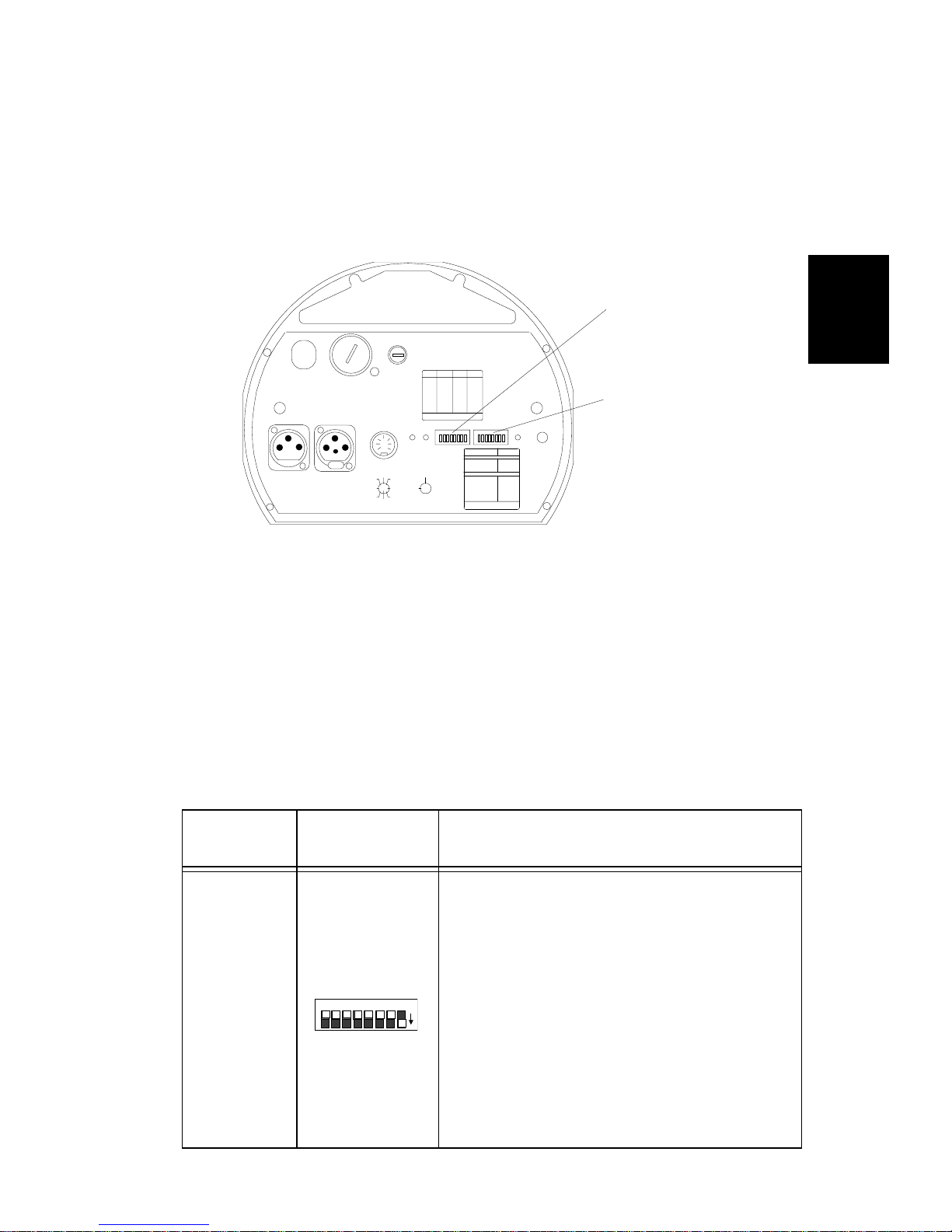
Once you determine which control mode to use, you must set the
fixture’s DIP switches to enable each Trac ksp ot fo r that control mode
and to assign fixture order (or starting channel). The personality and
address DIP switches (all factory set OFF) are located on the rear panel
of the fixture (see Figure 2-1).
address switch es
240
120
100
200
140
VOLTAGE SELECT
WARNIN G: CH ANGE VOLT AGE SE LECT ONL Y WI TH POWE R REMOV ED.
CAUTION: HOT REMOVE POWER BEFORE RELAMPING
WARNING: NOT FOR RESIDENTIAL USE. TO REDUCE THE RISK OF
FIRE OR ELECTRIC SHOCK, DO NOT EXPOSE TO RAIN OR MOISTURE,
NO USER SE RVI CEA B L E PARTS INSIDE. REFER SE RVI CING TO
QUALIFIED SERVICE PERSONNEL. FOR SAFE OPERATION CONSULT
USER MANUAL.
DATA OUTDATA IN
220
ANALOG IN
TILT
MSP EED
GOBO DIM
FUSE
ENABLEFAN
0-10V
SPECIAL AN AL OG
ANALOG
GND
COLOR
2
5
4
24 VDC
3761
OUT
PAN
8
(UNREG.)
FOR FUTH ER INFORMATION
SHUTTER
CONSULT USERS MANUAL
trackspot
LIGHTWA VE RESEARCH
2209 WEST BRAKER LAN E, AUSTIN, TEXAS U.S.A.
SWITCHESONSWITCHESADDRESS ADDRESS
ON
3,413
none01
1,3,414
102
2,3,415
203
1,2,3,416
1,204
517
305
1,518
1,306
2,519
2,307
1,2,520
1,2,308
3,521
409
1,3,522
1,410
2,3,523
2,411
1,2,3,524
1,2,412
FOR FURTHER INFORMATION
PLEASE CONSULT USER MANUAL
INPUT
GND
2
4
5
1673
8
ADDRESS
PERSONALITY
PERSONALITY SWITCHES
FIXT URE MODE SWITCHES 1-2
NORMAL RUN
SELF TEST
SET-UP
LAMP SAVE
CONTROL MODE SWITCHES 3-8
LIGHTWAVE CONTROL
DMX 1-256
DMX 257-51 2
ANALOG
AUDIO (SLAVE)
AUDIO (MASTER )
PAN INVERT
TILT I NVERT
FOR FURTHER INFORMATION
PLEASE CONSULT USER MANUAL
®
personality switches
MIC
AUDIO
ON
NONE
1
2
1,2
NONE
5
4
4,5
3
8
6
7
2
Figure 2-1. Address and personality DIP switches
For sample personality and address switch settings in each control
mode, see “Linking the Fixtures” on page 2-12.
Personality Switches
The personality switch settings determ ine the fixture’s ope rating mode
and/or control mode. See Table 2-2 below for a detailed description of
personality switch settings. For a quick-reference table of personality
switch settings, see “Personality Switch Settings” on page C-1.
Table 2-2. Personality switch settings - operating modes
Operating
Modes
Self Test
Personality
Switches ON
PERSONALITY
8 7 6 5 4 3 2 1
on
Description
Starts an internal self-diagnostic routine
which verifies that the major functions of
the fixture (pan, tilt, gobo wheel, color
wheel, and shutter) are working properly.
The fixture performs its homing procedure
once (you will h ear clattering sounds as the
shutter and mirror seek their home
position) and then repeats its self-test until
you set swit ch 1 OFF.
Note: Although a controller is not required
for the self-test, setting perso nality switc h 1
ON will override any controller that might
be attached to the fixture.
Trackspot User Manua l
Enabling the Control Mode
2-3
Page 26
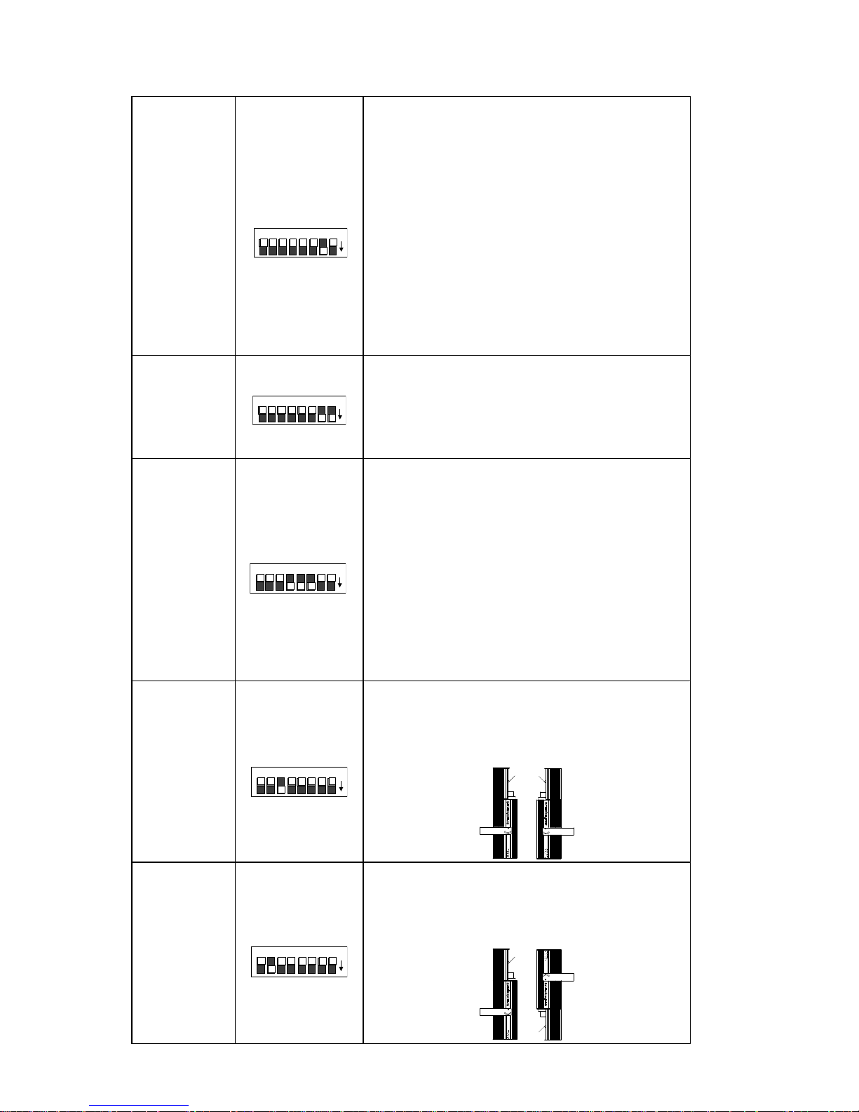
Table 2-2. Personality switch settings - operating modes
The fixture performs its homing procedure
and the lamp turns on, allowing you to
adjust the focus.
Toggle
address
switch 1 ON and OFF
while in setup mode to select a gobo
Set Up
(Focus)
PERSONALITY
8 7 6 5 4 3 2 1
pattern that helps you clearly see the
effects of your focusing adjustments.
on
Note: Although a controller is not required
for the self-test, setting perso nality switc h 1
ON will override any controller that might
be attached to the fixture.
For information on how to focu s the f ixture,
see “Focusing the Fixture” on page 2-17.
Increases the lamp life by lowering the
Lamp Save
PERSONALITY
8 7 6 5 4 3 2 1
applied voltage to the lamp by 10 percent.
on
This setting will decrease light output and
should be used to compens ate for hig h line
voltage.
Allows a fixture operating in LWR protocol
to override the Auto Dim feature.
The Auto Dim feature helps save the life of
the lamp as follows: when the shutter
Auto Dim
Override
(LWR)
PERSONALITY
8 7 6 5 4 3 2 1
closes, the lamp stays on for 1.5 - 3.0
on
minutes and then dims. When the shutter
is re-opened, the lamp instantly returns to
program intensity. Auto Dim occurs in all
control modes; however, this feature can
be overridden using LWR protocol when
these personality switches are ON.
Inverts the direction of the pan motor. This
setting allow s opposing fixtu res to res po nd
to mirror movement commands in the
same direction.
on
Pan Invert
PERSONALITY
8 7 6 5 4 3 2 1
PERSONALITY
Tilt Invert
2-4
Enabling the Control Mode
8 7 6 5 4 3 2 1
Inverts the direction of the tilt motor. This
setting allows opposing or upside down
fixtures to respond to mirror movement
commands in the same dire cti on.
on
Trackspot User Manual
Page 27
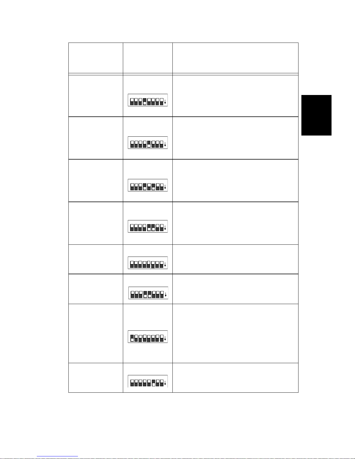
Table 2-3. Personality switch settings - control modes
Control
Modes
Low
Resolution
DMX mode
(channels 1-
256)
Low
Resolution
DMX mode
(channels
257-512)
High
Resolution
DMX mode
(channels 1-
256)
High
Resolution
DMX mode
(channels
257-512)
Personality
Switches
ON
PERSONALITY
8 7 6 5 4 3 2 1
PERSONALITY
8 7 6 5 4 3 2 1
PERSONALITY
8 7 6 5 4 3 2 1
PERSONALITY
8 7 6 5 4 3 2 1
on
on
on
on
Description
Configures the fixture to receive DMX
channels 1-256 in low resolution mode.
For more information, see “Low
Resolution Mode” on page A-1.
Configures the fixture to receive DMX
channels 257-512 in low resolution
mode. For more in form at ion , s ee “Lo w
Resolution Mode” on pag e A-1.
Configures the fixture to receive DMX
channels 1-256 in high resolution
mode. For more inform ation, see “High
Resolution Mode” on pag e A-1.
Configures the fixture to receive DMX
channels 257-512 in high resolution
mode. For more inform ation, see “High
Resolution Mode” on pag e A-1.
2
LWR protocol
Standard
Analog
Stand Alone
(Audio
Master)
Stand Alone
(Audio S lave)
PERSONALITY
8 7 6 5 4 3 2 1
PERSONALITY
8 7 6 5 4 3 2 1
PERSONALITY
8 7 6 5 4 3 2 1
PERSONALITY
8 7 6 5 4 3 2 1
The fixture must be controlled by LWR
on
protocol.
The fixture must be controlled by a 0-
on
10 volt standard analog controller.
Configures the fixture for stand alone
operation and des ignate s the fix ture as
the master. Also supp li es p ower to the
on
controller when used with the
Trackspot Spec ial Analog Controller.
Only one fixture in a li nk may be
selected as the maste r.
Configures the fixture for stand alone
on
operation and des ignate s the fix ture as
a slave.
Trackspot User Manua l
Enabling the Control Mode
2-5
Page 28
Address Switches
The address switch settings determine either the fixture’s numerical
order in a link or its starting channel. The control mode you chose
determines how you set the address switches. See Table 2-4 for
address switch settings.
Table 2-4. Address switch settings
Control Mode Address Switch Settings
Set each fixture’s addr ess switches to its starting
DMX 512
LWR Protocol
Standard Analog Set all address switches OFF.
Stand Alone
(Master/Slave)
channel using either high or low resolution mode
(see Table A-1 on page A-2).
Set each fixture’ s ad dres s s witc hes to represent the
fixture’s sequential numerical order in the link (see
Table C-2 on page C-2).
On the master Trackspot fixture, set the address
switches to represent the
fixtures in the link (including the master).
On each slave fixture, set the address switches to
represent the fixture’s numerical order in the link.
See Table C-2 on page C-2 for address switch
settings.
number of Trackspot
total
Installing Remote Enable/Disable
If your Trackspot fixtures are operating in stand alone mode, you can
remotely enable/disable the fixtures by installing either a remote SPST
switch or an external voltage source.
Warning: Unplug the fixture before installing remote
enable/disable.
You will need:
• either a SPST (single-pole, si ngle-throw) switch or a 10 volt so urc e
(such as a b a t t ery, a 0-10 volt analog control sourc e, etc.)
• suitable length of 18-24 gauge two-conductor wire (The gauge of
conductor you need will depend on the distance from your remote
switch or external voltage source to the master fixture.)
• one male 8-pin DIN connector
2-6
Installing Remote Enable/Disable
Trackspot User Manual
Page 29
SPST Switch
Note: Connect only the master fixture to the SPST switch.
To install an SPST switch:
1. Unplug the fixture.
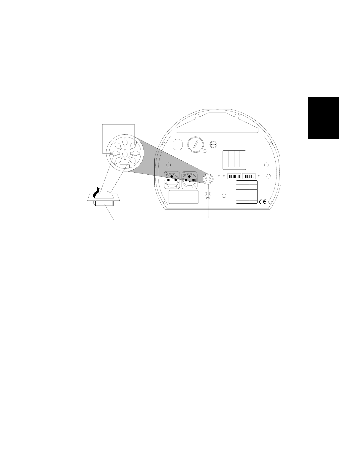
2. Locate the female Analog In connector on the rear panel of the
master Trackspot fixtur e (see Figure 2-2).
2
2
5
4
1 3
8
6
7
OFF ON
remote SPST switch
240
120
100
200
220
140
VOLTAGE SELECT
WARNING: CHANGE VOLTAGE SELECT ONLY WI TH POWER REMOVED.
CAUTION: HOT REMOVE POWER BEFORE RELAMPING
WARNING: NOT FOR RESIDENTIAL USE. TO REDUCE THE RISK OF
FIRE OR ELECTRI C SHOC K, DO NOT EX POSE TO R AIN OR MOI STURE ,
NO USER SERVICEABLE PARTS INSIDE. REFER SERVICING TO
QUALIFIED SERVICE PERSONNEL. FOR SAFE OPERATION CONSULT
USER MANUAL.
DATA OUTDATA IN
MODEL
SERIAL
FACTORY SET V AC
WATTS HZ
DATE QC
MSP EED
Analog In Connector
ANALOG IN
0-10V
ANALOG
GND
TILT
2
4
8
GOBO DIM
SHUTTER
trackspot
FUSE
FOR FURTHER INFORMATION
PLEASE CONSULT USER MANUAL
ENABLEFAN
SPECIAL AN AL OG
INPUT
GND
COLOR
2
4
5
5
24 VDC
1673
3761
OUT
PAN
8
(UNREG.)
FOR FUTH ER INFORMATION
CONSULT USERS MANUAL
LIGHTWA VE RESEARCH
2209 WEST BRAKER LAN E, AUSTIN, TEXAS U.S.A.
SWITCHESONSWITCHESADDRESS ADDRESS
ON
3,413
none01
1,3,414
102
2,3,415
203
1,2,3,416
1,204
517
305
1,518
1,306
2,519
2,307
1,2,520
1,2,308
3,521
409
1,3,522
1,410
2,3,523
2,411
1,2,3,524
1,2,412
ADDRESS
PERSONALITY SWITCHES
FIXT URE MODE SWITCHES 1-2
NORMAL RUN
SELF TEST
SET-UP
LAMP SAVE
CONTROL MODE SWITCHES 3-8
LIGHTWAVE CONTROL
DMX 1-256
DMX 257-51 2
ANALOG
AUDIO (SLAVE)
AUDIO (MASTER )
PAN INVERT
TILT I NVERT
FOR FURTHER INFORMATION
PLEASE CONSULT USER MANUAL
PERSONALITY
MIC
AUDIO
ON
NONE
1
2
1,2
NONE
5
4
4,5
3
8
6
7
Figure 2-2. Connecting a remote enable/disable switch to
the master fixture
3. Connect DIN pin 1 and pin 5 together (see Figure 2-2). You can
connect these pins either at the fixture or in the male 8-pin DIN
connector.
4. Connect DIN pin 1 and pin 3 to the SPST switch (see Figure 2-2).
When correctly connected to the SPST switch, the fixtures will be
enabled when the circuit is closed and disabled when the circuit is
open.
External Voltage Source
Note: Connect only the master fixture to the external voltage
source.
To install an external voltage source:
1. Unplug the fixture.
2. Locate the Analog In female connector on the rear panel of the
master Trackspot fixtur e (see Figure 2-2).
3. Connect analog DIN pin 1 and pin 5 together (see Figure 2-2). You
can connect these pins either at the fixture end or in the mal e 8-pin
DIN connector.
Trackspot User Manua l
Installing Remote Enable/Disable
2-7
Page 30
4. Connect analog DIN pin 2 to the negative voltage and analog DIN
pin 3 to the positive voltage using the conductor.
When correctly connected to the external voltage source, the fixtures
will be enabled when you apply 10 to 40 volts DC on pin 3. The fixtures
will be disabled when you apply zero volts DC on pin 3.
Mounting the Fixture
Trackspot is designed to be mounted in any orientation. Before
mounting the fixture, follow the precautions and suggestions below:
• Verify the input voltage you are using matches the Trackspot
fixture’s voltage selection switch. Unplug the fixture before
turning the voltage select switch. See “Specifications” on page
Intro-4 and “Selecting the Voltage” on page 1-3 for more
information.
• When you mount or position the fixture, make sure that no
obstacles cover or block the fixture’s cooling fan intake (see Figure
3-1 on page 3-2). A blocked airpath could result in damage to the
fixture.
Heed the following warnings to guard against personal injury and
damage to the fixture.
Caution: Equipment suitable for dry locations only.
Do not expose this equipment to rain or
moisture.
Warnings: 1) Do not mount on a flammable surface.
2) Maintain a minimum distance of 1.0
meter (3.28 feet) from combustible
1m
materials.
3) Maintain a minimum distance of 1.0
meter (3.28 feet) from lighted object.
This means the fixture must be
positioned at least 1 meter away from
the object it is illuminating.
Additional Hardware
T o mount the fixture, you will need a truss or other support system, one
or more safety cables, and one or more clamps.
Truss or Other Support System
If you are mounting the fixture on a truss or another type of support,
verify the truss or support will handle the weight of all the devices you
are mounting. The Trackspot fixture weight is listed in
“Specifications” on page Intro-4.
2-8
Mounting the Fixture
Trackspot User Manual
Page 31

Safety Cable
High End Systems strongly recommends that you use safety cable
when mounting any fixture. You must supply your own safety cable
and verify the cable is capable of supporting the weight of the
Trackspot fixture. You can order galvanized safety cables from your
High End Systems dealer/distributor (see “Optional Accessories” on
page Intro-6).
Clamp
You must supply your own clamp(s) and verify the clamp is capable of
supporting the weight of the Trackspot fixture. You can order deluxe
C-clamps for a two-inch truss from your High End Systems dealer/
distributor (see “Optional Accessories” on page Intro-6).
Caution: Make sure the fixture cannot be rotated 360°.
(Using two clamps is a good way to make sure
the fixture cannot be rotated in a full circle.)
Allowing the fixture to rotate 360° could
loosen the clamp mounting bolts and cause
the fixture to fall from its clamp.
2
Note: Due to the wide variety of possible lighting designs, High
End Systems cannot make specific mounting
recommendations. Consider the following procedure as a
suggested guideline only .
Suggested mounting procedure:
1. Unplug the fixture. If the fixture has been operating, allow t h e
fixture to cool for at least 5 minutes.
2. Use two people to mount each Trackspot fixture: one person to
hold the fixture while it is being secured in place, and one person
to the secure the fixture to its support and attach safety cables.
3. Always stand on a firm, stable surface when mounting a fixture to
its support. The fixture should be at a height where you can
comfortably work on it, and should either be resting on a stable
surface, or held in a stable manner. Do not allow one person to
both support and mount the fixture.
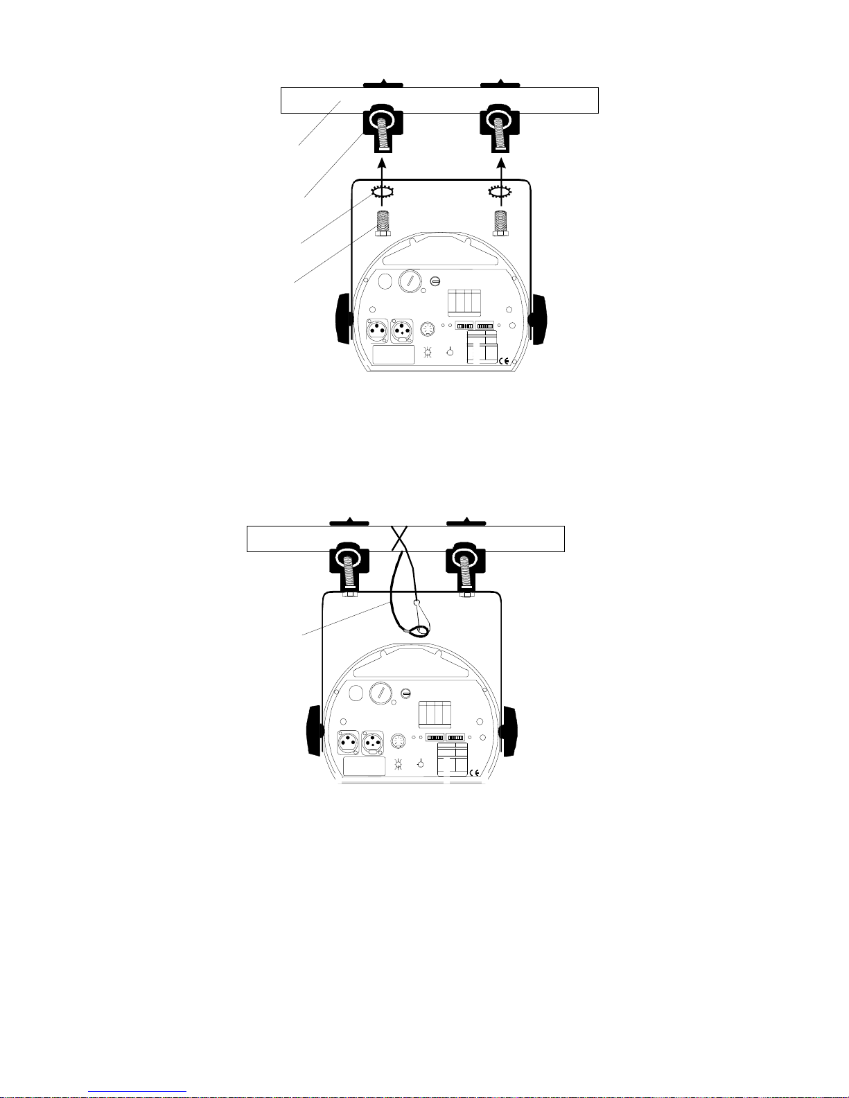
4. Attach suitable clamp(s) through the holes on top of the yoke. If
you are attaching one clamp, use the middle hole on the yoke. If
you are attaching two clamps (as shown in Figure 2-3), attach one
clamp to each of the two outer holes on the yoke. Use locking
washers when attaching the clamp(s) to the yoke.
Trackspot User Manua l
Mounting the Fixture
2-9
Page 32
truss or other
support structure
C-clamp
locking
washer
240
clamp
mounting bolt
200
140
VOLTAGE SELEC T
WARNING: CHANG E VOLTAGE SELECT ONL Y WITH POWER REMOVED.
CAUTION: HOT REMOVE POWER BEFORE REL AMPING
WARNING: NOT FO R RESIDENTIAL USE. TO REDUCE THE RISK OF
FIRE OR ELECTRIC SHOCK, DO NOT EXPOSE TO RAIN OR MOISTURE,
NO USER SERVICEABLE PARTS INSIDE. REFER SERVICING TO
QUALIFIED SERVICE PERSONNEL. FOR SAFE OPERATION CONSULT
USER MANUAL.
DATA IN
DATA OUT
MODEL
SERIAL
FACTORY SET VAC
WATTS HZ
DATE QC
220
MSPEED
GOBO DIM
ANALOG IN
0-10V
ANALOG
GND
TILT
2
5
4
3761
8
SHUTTER
trackspot
SWITCHESONSWITCHESADDRESS ADDRESS
FUSE
none01
102
203
1,204
305
1,306
2,307
1,2,308
409
1,410
2,411
1,2,412
FOR FURTHER INFORMATION
PLEASE CONSULT USER MANUAL
SPECIAL ANALOG
INPUT
GND
COLOR
2
4
5
24 VDC
1673
OUT
8
PAN
(UNREG.)
FOR FUTHER INFORMATION
CONSULT USERS MANUAL
2209 WEST BRAKER LANE, AUSTIN, TEXA S U.S. A.
ON
120
100
Figure 2-3. Attaching two C-clamps to the Trackspot yoke
5. Tighten the clamp(s) firmly to the yoke and to the support.
6. Loop one or more suitable safety cables around the support and
the top of the yoke (see Figure 2-4). The safety cable(s) can be
looped one or more times around the truss or support.
LIGHTW A VE RESE A RC H
ADDRESSENABL EFAN
3,413
1,3,414
2,3,415
1,2,3,416
517
1,518
2,519
1,2,520
3,521
1,3,522
2,3,523
1,2,3,524
PERSONALITY
FIXTURE MODE SWITCHES 1-2
NORMAL RUN
SELF TEST
SET-UP
LAMP SAVE
CONTROL MODE SWITCHES 3-8
LIGHTWAVE CONTROL
DMX 1-256
DMX 257-512
ANALOG
AUDIO (SLAVE)
AUDIO (MASTER)
PAN INVERT
TILT INVERT
FOR FURTHER INFORMATION
PLEASE CONSULT USER MANUAL
PERS ONALI TY
®
AUDIO MIC
SWITCHES
ON
NONE
1
2
1,2
NONE
5
4
4,5
3
8
6
7
safety cable
240
120
100
200
140
VOLTAGE SELE CT
WARNING: CHANGE VOLTAGE SELECT ONLY WITH POWER REMOVED.
CAUTION: HOT REMO VE POWE R BEFORE RELAMPIN G
WARNING: NOT FO R RESI DENT IAL US E. TO RE DUC E THE R ISK O F
FIRE OR ELECTRIC SHOCK, DO NOT EXPOSE TO RAIN OR MOISTURE,
NO USER SERVICEABLE PARTS INSIDE. REFER SERVICING TO
QUALIFIED SERVICE PERSONNEL. FOR SAFE OPERATION CONSULT
USER MANUAL.
DATA OUTDATA IN
MODEL
SERIAL
FACTORY SET VAC
WATTS HZ
DATE QC
220
MSPEED
ANALOG IN
TILT
GOBO DIM
0-10V
ANALOG
GND
2
5
4
3761
8
SHUTTER
trackspot
SWITCHESONSWITCHESADDRESS ADDRESS
FUSE
none01
102
203
1,204
305
1,306
2,307
1,2,308
409
1,410
2,411
1,2,412
FOR FURTHER INFORMATION
PLEASE CONSULT USER MANUAL
SPECIAL ANALOG
INPUT
GND
COLOR
2
4
5
24 VDC
1673
OUT
PAN
8
(UNREG.)
FOR FUTHER INFORMATION
CONSULT USERS MANUAL
2209 WEST BRAKER LANE, AUSTIN, TEXAS U.S.A.
ON
LIGHTW A VE RESE A RC H
3,413
1,3,414
2,3,415
1,2,3,416
517
1,518
2,519
1,2,520
3,521
1,3,522
2,3,523
1,2,3,524
PERSONALITY SWITCHES
FIXTU RE MODE SWITCH ES 1-2
NORMAL RUN
SELF TEST
SET-UP
LAMP SAVE
CONTROL MODE SWITCHES 3-8
LIGHTWAVE CONTROL
DMX 1-256
DMX 257-512
ANALOG
AUDIO (SLAVE)
AUDIO (MASTER)
PAN INVERT
TILT INVERT
FOR FURTHER INFORMATION
PLEASE CONSULT USER MANUAL
®
AUDIO MI CPERS ONALI TYADDRESSEN ABLEFAN
ON
NONE
1
2
1,2
NONE
5
4
4,5
3
8
6
7
Figure 2-4. Attaching a safety cable to the mounted fixture
Obtaining Cabling and Terminators
There are two main types of cabling you can use: microphone cable
and data-grade cable. Although pin-compatible microphone cable is
suitable for small-scale configurations, data cable is recommended,
especially for longer cable runs. Data cable is designed to carry a
higher-quality signal with less susceptibility to electromagnetic
interference. Belden
for use with Trackspot fixtures.
®
9841 data-grade cabli ng is highly recommend ed
2-10
Obtaining Cabling and Terminators
Trackspot User Manual
Page 33
Constructing Cabling
Figure 2-6. Data
cable terminator
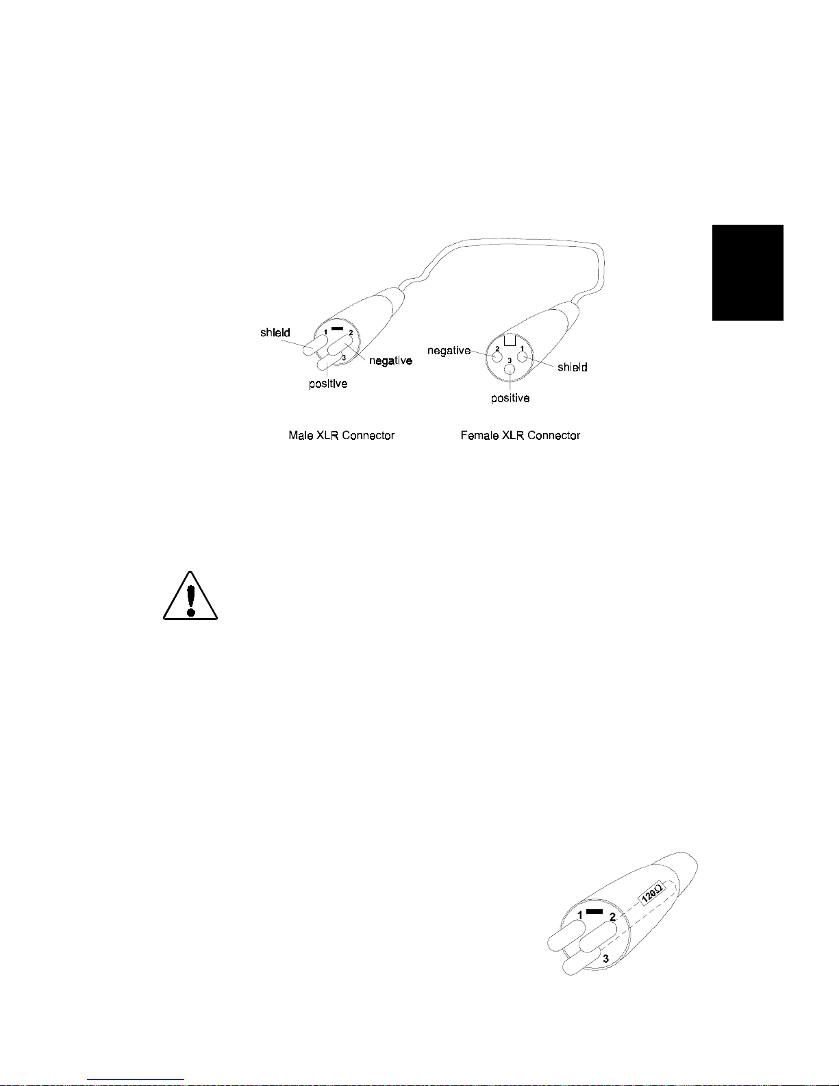
If you need to construct cabling, you must use a shielded, two conductor cable with a male 3-pin XLR connector on one end and a
female 3-pin XLR connector on the other end. Pin one is the shield
(ground), pin two is the data complement (negative), and pin three is
the data true (positive) (see Figure 2-5). For more information on
cabling and connector specifications, see “Specifications” on page
Intro-4.
Figure 2-5. XLR 3-pin connectors
2
You should test each cable with a voltage/ohm meter (VOM) to verify
correct polarity and to make sure that the negative and positive pins
are not grounded or shorted to the shield or to each other. Also, make
sure that pin 1 is shielded.
Caution: D o not use the ground lug on the XLR
connectors. Do not connect the shield to
ground or al low contact to ground.
Grounding the shield could cause a ground
loop and/or erratic behavior.
Constructing Terminators
If you chose to use standard analog control, you do not need to attach a
terminator to the last device on each link. However, for all other
control modes, the last device on each link must have a 120 ohm, 1/4
watt (minimum) terminator attached to its Data Out connector.
You can construct terminators by following the instructions below:
1. Obtain a male XLR connector.
2. Disassemble the connector.
3. Solder a 120 ohm resistor, minimum of 1/4
watt, between pins 2 and 3 (see Figure 2-6).
4. Reassemble the XLR connector.
5. Install the terminator in the Data Out
connector of the last fixture in the link.
Trackspot User Manua l
Obtaining Cabling and Terminators
2-11
Page 34

Linking the Fixtures
The control mode you use (DMX 512 protocol, LWR protocol, standard
analog, or stand alone operation) determines how you will link the
fixtures to a controller with data cabling. If you decided to use stand
alone operat i o n wit h n o controller, the master fix t ure serves as the
controller for linking purposes. Follow the instructions listed below for
link information corresponding to the control mode you chose.
DMX 512 Protocol
If you chose DMX 512 protocol as your control mode, you must operate
your fixtures either in low resolution or high resolution. Control
options available on your DMX controller will determine whether you
can operate your fixtures in low or high resolution mode. For more
information, see “Start Channels and Construct Parameters” on page
A-1.
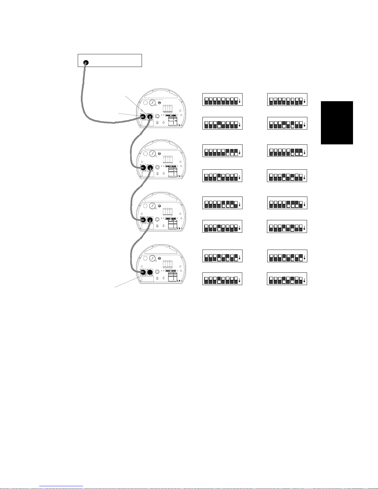
To link Trackspot fixtures using a controller with DMX 512 protocol,
follow the steps listed below:
1. On all fixtures, set the address switches to the appropriate DMX
512 start channel and set the personality switches to enable either
low or high resolution mode.
For personality and address switch settings in DMX 512 protocol,
see T able A -1 on page A-2.
2. Link the DMX 512 controller and fixtures together with 3-pin XLR
two-conductor data cables. Plug the male end of a data cable into
the Data Out connector on the rear panel of the controller. Plug
the female end of that data cable into the Data In connector of the
first fixture. Continue using this method to link the remainder of
the fixtures together (see Figure 2-7).
2-12
Linking the Fixtures
Trackspot User Manual
Page 35
DMX 512
Protocol controller
Low Resolution
Channel s 1-256
High Resolution
Channel s 1-256
data out
data in
terminator
WARNING: CHANGE VOLTAGE SELECT ONLY WITH POWER REMOVED.
CAUTION: HOT R EMOVE POWER BEFORE RELAMPING
WARNING: NOT FOR RESIDENTIAL USE. TO REDUCE THE RISK OF
FIRE OR ELECTRIC SHOCK, DO NOT EXPOSE TO RAIN OR MOISTURE,
NO USER SERVICEABLE PARTS INSIDE. REFER SERVICING TO
QUALIFIED SERVICE PERSONNEL. FOR SAFE OPERATION CONSULT
USER MANUAL.
MODEL
SERIAL
FACTORY SET VA C
WATTS HZ
DATE QC
WARNING: CHANGE VOLTAGE SELECT ONLY WITH POWER REMOVED.
CAUTION: HOT R EMOVE POWER BEFORE RELAMPING
WARNING: NOT FOR RESIDENTIAL USE. TO REDUCE THE RISK OF
FIRE OR ELECTRIC SHOCK, DO NOT EXPOSE TO RAIN OR MOISTURE,
NO USER SERVICEABLE PARTS INSIDE. REFER SERVICING TO
QUALIFIED SERVICE PERSONNEL. FOR SAFE OPERATION CONSULT
USER MANUAL.
MODEL
SERIAL
FACTORY SET VA C
WATTS HZ
DATE QC
WARNING: CHANGE VOLTAGE SELECT ONLY WITH POWER REMOVED.
CAUTION: HOT R EMOVE POWER BEFORE RELAMPING
WARNING: NOT FOR RESIDENTIAL USE. TO REDUCE THE RISK OF
FIRE OR ELECTRIC SHOCK, DO NOT EXPOSE TO RAIN OR MOISTURE,
NO USER SERVICEABLE PARTS INSIDE. REFER SERVICING TO
QUALIFIED SERVICE PERSONNEL. FOR SAFE OPERATION CONSULT
USER MANUAL.
MODEL
SERIAL
FACTORY SET VA C
WATTS HZ
DATE QC
WARNING: CHANGE VOLTAGE SELECT ONLY WITH POWER REMOVED.
CAUTION: HOT R EMOVE POWER BEFORE RELAMPING
WARNING: NOT FOR RESIDENTIAL USE. TO REDUCE THE RISK OF
FIRE OR ELECTRIC SHOCK, DO NOT EXPOSE TO RAIN OR MOISTURE,
NO USER SERVICEABLE PARTS INSIDE. REFER SERVICING TO
QUALIFIED SERVICE PERSONNEL. FOR SAFE OPERATION CONSULT
USER MANUAL.
MODEL
SERIAL
FACTORY SET VA C
WATTS HZ
DATE QC
24
0
120
100
200
220
140
FUSE
VOLTAGE SELECT
DATA OUTDATA IN
ANALOG IN
0-10V
ANALOG
GND
TILT
COLOR
5
42
24 VDC
OUT
MSPEED
3761
PAN
8
(UNREG.)
GOBO DIM
FOR FUTHER INFORMATION
SHUTTER
CONSULT USERS MANUAL
fixture 1
240
120
100
200
220
140
FUSE
VOLTAGE SELECT
DATA OUTDATA IN
ANALOG IN
0-10V
ANALOG
GND
TILT
COLOR
5
42
24 VDC
3761
OUT
MSPEED
PAN
8
(UNREG.)
GOBO DIM
FOR FUTHER INFORMATION
SHUTTER
CONSULT USERS MANUAL
fixture 2
240
120
100
200
220
140
FUSE
VOLTAGE SELECT
DATA OUTDATA IN
ANALOG IN
0-10V
ANALOG
GND
TILT
COLOR
5
42
24 VDC
OUT
MSPEED
3761
PAN
8
(UNREG.)
GOBO DIM
FOR FUTHER INFORMATION
SHUTTER
CONSULT USERS MANUAL
fixture 3
240
120
100
200
220
140
FUSE
VOLTAGE SELECT
DATA OUTDATA IN
ANALOG IN
0-10V
ANALOG
GND
TILT
COLOR
5
42
24 VDC
3761
OUT
MSPEED
8
PAN
(UNREG.)
GOBO DIM
FOR FUTHER INFORMATION
SHUTTER
CONSULT USERS MANUAL
fixture 4
trackspo t
LIGHTWAVE RESEARCH
2209 WEST BRAKER LANE, AUSTIN, TEXAS U.S.A.
SWITCHESONSWITCHESADDRE SS AD DRESS
ON
none01
102
203
1,204
305
1,306
2,307
1,2,308
409
1,410
2,411
1,2,412
FOR FURTHER INFORMATION
PLEASE CONSULT USER MANUAL
ADDR ESSENAB LEFAN
PERSONALITY
FIXTURE MODE SWITCHES 1-2
NORMAL RUN
SELF TEST
SET-UP
SPECIAL ANAL OG
LAMP SAVE
INPUT
CONTROL MODE SWITCHES 3-8
GND
LIGHTWAVE CONTROL
DMX 1-256
DMX 257-512
2
4
5
ANALOG
1
3
8
AUDIO (SLAVE)
6 7
AUDIO (MASTER)
PAN INVERT
TILT INVERT
trackspo t
LIGHTWAVE RESEARCH
2209 WEST BRAKER LANE, AUSTIN, TEXAS U.S.A.
SWITCHESONSWITCHESADDRE SS AD DRESS
ON
none01
102
203
1,204
305
1,306
2,307
1,2,308
409
1,410
2,411
1,2,412
FOR FURTHER INFORMATION
PLEASE C ONSULT USER MANUAL
PERSONALITY SWITCHES
FIXTURE MODE SWITCHES 1-2
NORMAL RUN
SELF TEST
SET-UP
SPECIAL ANAL OG
LAMP SAVE
INPUT
CONTROL MODE SWITCHES 3-8
GND
LIGHTWAVE CONTROL
DMX 1-256
DMX 257-512
2
4
5
ANALOG
1
3
8
AUDIO (SLAVE)
6 7
AUDIO (MASTER)
PAN INVERT
TILT INVERT
trackspo t
LIGHTWAVE RESEARCH
2209 WEST BRAKER LANE, AUSTIN, TEXAS U.S.A.
SWITCHESONSWITCHESADDRE SS AD DRESS
ON
none01
102
203
1,204
305
1,306
2,307
1,2,308
409
1,410
2,411
1,2,412
FOR FURTHER INFORMATION
PLEASE CONSULT USER MANUAL
ADDR ESSENAB LEFAN
PERSONALITY SWITCHES
FIXTURE MODE SWITCHES 1-2
NORMAL RUN
SELF TEST
SET-UP
SPECIAL ANAL OG
LAMP SAVE
INPUT
CONTROL MODE SWITCHES 3-8
GND
LIGHTWAVE CONTROL
DMX 1-256
DMX 257-512
2
4
5
ANALOG
1
3
8
AUDIO (SLAVE)
6 7
AUDIO (MASTER)
PAN INVERT
TILT INVERT
trackspo t
LIGHTWAVE RESEARCH
2209 WEST BRAKER LANE, AUSTIN, TEXAS U.S.A.
SWITCHESONSWITCHESADDRE SSADDRESS
ON
none01
102
203
1,204
305
1,306
2,307
1,2,308
409
1,410
2,411
1,2,412
FOR FURTHER INFORMATION
PLEASE CONSULT USER MANUAL
ADDR ESSENAB LEFAN
PERSONALITY
FIXTURE MODE SWITCHES 1-2
NORMAL RUN
SELF TEST
SET-UP
SPECIAL ANAL OG
LAMP SAVE
INPUT
CONTROL MODE SWITCHES 3-8
GND
LIGHTWAVE CONTROL
DMX 1-256
DMX 257-512
2
4
5
ANALOG
1673
8
AUDIO (SLAVE)
AUDIO (MASTER)
PAN INVERT
TILT INVERT
3,413
1,3,414
2,3,415
1,2,3,416
517
1,518
2,519
1,2,520
3,521
1,3,522
2,3,523
1,2,3,524
FOR FURTHER INFORMATION
PLEASE CONSULT USER MANUAL
3,413
1,3,414
2,3,415
1,2,3,416
517
1,518
2,519
1,2,520
3,521
1,3,522
2,3,523
1,2,3,524
FOR FURTHER INFORMATION
PLEASE CONSULT USER MANUAL
3,413
1,3,414
2,3,415
1,2,3,416
517
1,518
2,519
1,2,520
3,521
1,3,522
2,3,523
1,2,3,524
FOR FURTHER INFORMATION
PLEASE C ONSULT USER MANUAL
3,413
1,3,414
2,3,415
1,2,3,416
517
1,518
2,519
1,2,520
3,521
1,3,522
2,3,523
1,2,3,524
FOR FURTHER INFORMATION
PLEASE C ONSULT USER MANUAL
ADDRESS
®
PERSON ALITY
AUDIO MIC
SWITCHES
ON
NONE
1
2
1,2
NONE
5
4
4,5
3
8
6
7
8 7 6 5 4 3 2 1
PERSONALITY
8 7 6 5 4 3 2 1
on
on
ADDRESS
8 7 6 5 4 3 2 1
PERSONALITY
8 7 6 5 4 3 2 1
on
on
2
ADDRESS
®
AUDIO MICPERSO NALIT YADDR ESSENAB LEFAN
ON
NONE
1
2
1,2
NONE
5
4
4,5
3
8
6
7
8 7 6 5 4 3 2 1
PERSONALITY
8 7 6 5 4 3 2 1
on
on
ADDRESS
®
PERSON ALITY
AUDIO MIC
ON
NONE
1
2
1,2
NONE
5
4
4,5
3
8
6
7
8 7 6 5 4 3 2 1
PERSONALITY
8 7 6 5 4 3 2 1
on
on
ADDRESS
®
PERSON ALITY
AUDIO MIC
SWITCHES
ON
NONE
1
2
1,2
NONE
5
4
4,5
3
8
6
7
8 7 6 5 4 3 2 1
PERSONALITY
8 7 6 5 4 3 2 1
on
on
ADDRESS
8 7 6 5 4 3 2 1
PERSONALITY
8 7 6 5 4 3 2 1
ADDRESS
8 7 6 5 4 3 2 1
PERSONALITY
8 7 6 5 4 3 2 1
ADDRESS
8 7 6 5 4 3 2 1
PERSONALITY
8 7 6 5 4 3 2 1
on
on
on
on
on
on
Figure 2-7. Linking fixtures to a DMX 512 protocol controller
Trackspot User Manua l
Linking the Fixtures
2-13
Page 36
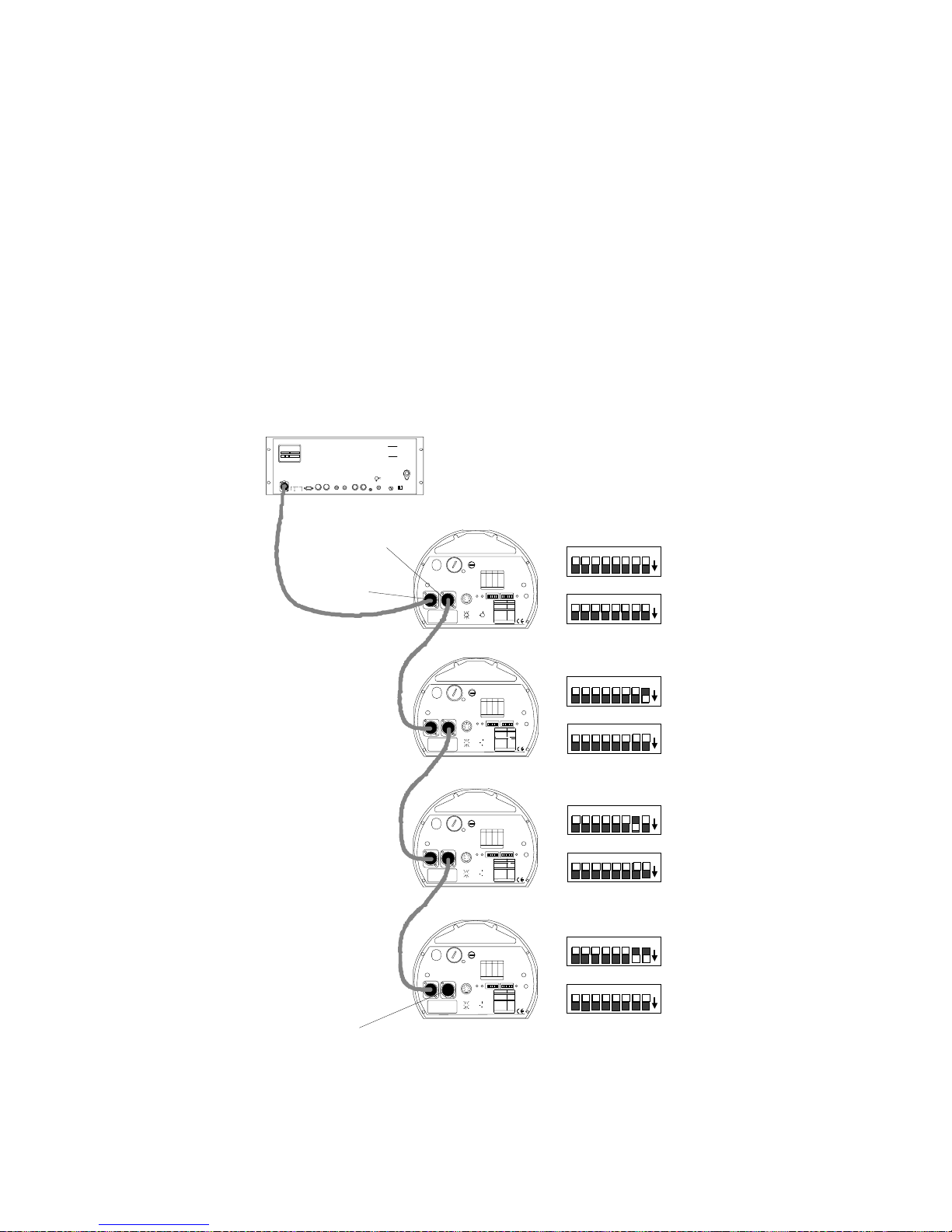
LWR Protocol
T o link T rackspo t fixtures using a controller with LWR protocol, follow
the steps listed below:
1. On each fixture, set all personality switches OFF and set the
address switches to the fixture’s numerical order in the link. See
Table C-2 on page C-2 for address switch settings.
2. Link the controller and fixtures together with 3-pin XLR twoconductor data cables. Plug the male end of a data cable into the
Data Out connector on the rear panel of the controller. Plug the
female end of that data cable into the Data In connector of the first
fixture. Continue using this method to link the remainder of the
fixtures together (see Figure 2-8).
LWR Protocol controller
2209 WEST BRAKER LANE
AUSTIN, TEXAS USA 78758
SERIAL # DATE MFG
QC
ROM# VOLTAGE
DATA LIN K
OUT
cyberlight
LIGHTWAVE RESEARCH
AUSTIN, TEXAS USA
Install ation and oper ating
procedur es available i n
user manual .
MIDI
OUT
IN
SERIAL POR T
MASTER
PERSONAL ITY
RS-232
A B
1 2 3 4
1 2 3 4 5 6 7 8
WARNING
To reduce the risk of fire or
electr ic shock, do not exp ose
this device to rain or moisture.
CAUTION
To prevent electric shock, do not
remove cover. No user serviceable pa rt s in side. Ref er servi cing to qualified service personnel .
L
R
ANALOG INPUT S
STEREO
CAUTION
1-6
7-12
AUDIO
voltage
FUSE
SLAVE
select
REMOTE
INPUT
1.6 amp
ENABLE
115
data out
data in
terminator
WARNING: CHANGE VOLTAGE SELECT ONLY WITH POWER REMOVED.
CAUTION: HOT REMOVE POWER BEFORE RELAMPING
WARNING: NOT FOR RESIDENTIAL USE. TO REDUCE THE RISK OF
FIRE OR ELECTRIC SHOCK, DO NOT EXPOSE TO RAIN OR MOISTURE,
NO USER SERVICEABLE PARTS INSIDE. REFER SERVICING TO
QUALIFIED SERVICE PERSONN EL. FOR SAFE OPERATION CONSULT
USER MANUAL.
MODEL
SERIAL
FACTORY SET VAC
WATTS HZ
DATE QC
WARNING: CHANGE VOLTAGE SELECT ONLY WITH POWER REMOVED.
CAUTION: HOT R EMOVE POWER BEFORE RELAMPING
WARNING: NOT FOR RESIDENTIAL USE. TO REDUCE THE RISK OF
FIRE OR ELECTRIC SHOCK, DO NOT EXPOSE TO RAIN OR MOISTURE,
NO USER SERVICEABLE PARTS INSIDE. REFER SERVICING TO
QUALIFIED SERVICE PERSONN EL. FOR SAFE OPERATION CONSULT
USER MANUAL.
MODEL
SERIAL
FACTORY SET VAC
WATTS HZ
DATE QC
WARNING: CHANGE VOLTAGE SELECT ONLY WITH POWER REMOVED.
CAUTION: HOT REMOVE POWER BEFORE RELAMPING
WARNING: NOT FOR RESIDENTIAL USE. TO REDUCE THE RISK OF
FIRE OR ELECTRIC SHOCK, DO NOT EXPOSE TO RAIN OR MOISTURE,
NO USER SERVICEABLE PARTS INSIDE. REFER SERVICING TO
QUALIFIED SERVICE PERSONN EL. FOR SAFE OPERATION CONSULT
USER MANUAL.
MODEL
SERIAL
FACTORY SET VAC
WATTS HZ
DATE QC
WARNING: CHANGE VOLTAGE SELECT ONLY WITH POWER REMOVED.
CAUTION: HOT REMOVE POWER BEFORE RELAMPING
WARNING: NOT FOR RESIDENTIAL USE. TO REDUCE THE RISK OF
FIRE OR ELECTRIC SHOCK, DO NOT EXPOSE TO RAIN OR MOISTURE,
NO USER SERVICEABLE PARTS INSIDE. REFER SERVICING TO
QUALIFIED SERVICE PERSONN EL. FOR SAFE OPERATION CONSULT
USER MANUAL.
MODEL
SERIAL
FACTORY SET VAC
WATTS HZ
DATE QC
DATA OUTDATA IN
DATA OUTDATA IN
DATA OUTDATA IN
DATA OUTDATA IN
240
120
100
200
220
140
FUSE
VOLTAGE SELECT
ANALOG IN
SPECIAL ANALOG
0-10V
ANALOG
GND
COLOR
TILT
5
42
24 VDC
3761
OUT
MSPEED
PAN
8
(UNREG.)
GOBO DIM
FOR FUTHER INFORMATION
SHUTTER
CONSULT USERS MANUAL
fixture 1
240
120
100
200
220
140
FUSE
VOLTAGE SELECT
ANALOG IN
SPECIAL ANALOG
0-10V
ANALOG
GND
TILT
COLOR
2
24 VDC
5
4
3761
OUT
MSPEED
PAN
8
(UNREG.)
GOBO DIM
FOR FUTHER INFORMATION
SHUTTER
CONSULT USERS MANUAL
fixture 2
240
120
100
200
220
140
FUSE
VOLTAGE SELECT
ANALOG IN
SPECIAL ANALOG
0-10V
ANALOG
GND
COLOR
TILT
5
42
24 VDC
3761
OUT
MSPEED
PAN
8
(UNREG.)
GOBO DIM
FOR FUTHER INFORMATION
SHUTTER
CONSULT USERS MANUAL
fixture 3
120
240
100
200
220
140
FUSE
VOLTAGE SELECT
ANALOG IN
0-10V
SPECIAL ANALOG
ANALOG
GND
COLOR
TILT
2
5
4
24 VDC
3761
8
OUT
MSPEED
PAN
(UNREG.)
GOBO DIM
FOR FUTHER INFORMATION
SHUTTER
CONSULT USERS MANUAL
fixture 4
trackspot
LIGHTWAVE RES EARCH
2209 WEST BRAKER LANE, AUSTIN, TEXAS U.S.A.
SWITCHESONSWITCHESADDRESS ADDRESS
ON
3,413
none01
1,3,414
102
2,3,415
203
1,2,3,416
1,204
517
305
1,518
1,306
2,519
2,307
1,2,520
1,2,308
3,521
409
1,3,522
1,410
2,3,523
2,411
1,2,3,524
1,2,412
FOR FURTHER INFORMATION
PLEASE CONSULT USER MANUAL
PERSONALITY SWITCHES
FIXTURE MODE SWITCHES 1-2
NORMAL RUN
SELF TEST
SET-UP
LAMP SAVE
INPUT
CONTROL MODE SWITC HES 3-8
GND
LIGHTWAVE CONTROL
DMX 1-256
DMX 257-512
2
4
5
ANALOG
1
3
8
AUDIO (SLAVE)
6 7
AUDIO (MASTER)
PAN INVERT
TILT INVERT
FOR FURTHER INFORMATION
PLEASE CONSULT USER MANUAL
trackspot
LIGHTWAVE RES EARCH
2209 WEST BRAKER LANE, AUSTIN, TEXAS U.S.A.
SWITCHESONSWITCHESADDRESS ADDRESS
ON
3,413
none01
1,3,414
102
2,3,415
203
1,2,3,416
1,204
517
305
1,518
1,306
2,519
2,307
1,2,520
1,2,308
3,521
409
1,3,522
1,410
2,3,523
2,411
1,2,3,524
1,2,412
FOR FURTHER INFORMATION
PLEASE CONSULT USER MANUAL
PERSONALITY SWITCHES
FIXTURE MODE SWITCHES 1-2
NORMAL RUN
SELF TEST
SET-UP
LAMP SAVE
INPUT
CONTROL MODE SWITC HES 3-8
GND
LIGHTWAVE CONTROL
DMX 1-256
DMX 257-512
2
4
5
ANALOG
1
3
8
AUDIO (SLAVE)
6 7
AUDIO (MASTER)
PAN INVERT
TILT INVERT
FOR FURTHER INFORMATION
PLEASE CONSULT USER MANUAL
trackspot
LIGHTWAVE RES EARCH
2209 WEST BRAKER LANE, AUSTIN, TEXAS U.S.A.
SWITCHESONSWITCHESADDRESS ADDRESS
ON
3,413
none01
1,3,414
102
2,3,415
203
1,2,3,416
1,204
517
305
1,518
1,306
2,519
2,307
1,2,520
1,2,308
3,521
409
1,3,522
1,410
2,3,523
2,411
1,2,3,524
1,2,412
FOR FURTHER INFORMATION
PLEASE CONSULT USER MANUAL
PERSONALITY SWITCHES
FIXTURE MODE SWITCHES 1-2
NORMAL RUN
SELF TEST
SET-UP
LAMP SAVE
INPUT
CONTROL MODE SWITC HES 3-8
GND
LIGHTWAVE CONTROL
DMX 1-256
DMX 257-512
2
4
5
ANALOG
1
3
8
AUDIO (SLAVE)
6 7
AUDIO (MASTER)
PAN INVERT
TILT INVERT
FOR FURTHER INFORMATION
PLEASE CONSULT USER MANUAL
trackspot
LIGHTWAVE RES EARCH
2209 WEST BRAKER LANE, AUSTIN, TEXAS U.S.A.
SWITCHESONSWITCHESADDRESS ADDRESS
ON
3,413
none01
1,3,414
102
2,3,415
203
1,2,3,416
1,204
517
305
1,518
1,306
2,519
2,307
1,2,520
1,2,308
3,521
409
1,3,522
1,410
2,3,523
2,411
1,2,3,524
1,2,412
FOR FURTHER INFORMATION
PLEASE CONSULT USER MANUAL
PERSONALITY SWITCHES
FIXTURE MODE SWITCHES 1-2
NORMAL RUN
SELF TEST
SET-UP
LAMP SAVE
INPUT
CONTROL MODE SWITC HES 3-8
GND
LIGHTWAVE CONTROL
DMX 1-256
DMX 257-512
2
4
5
ANALOG
1673
8
AUDIO (SLAVE)
AUDIO (MASTER)
PAN INVERT
TILT INVERT
FOR FURTHER INFORMATION
PLEASE CONSULT USER MANUAL
ADDRESS
®
AUDIO MICPERSO NALITYADD RESSENABLEFAN
ON
NONE
1
2
1,2
NONE
5
4
4,5
3
8
6
7
®
AUDIO MICPE RSONALI TYADDR ESSENABLEFAN
ON
NONE
1
2
1,2
NONE
5
4
4,5
3
8
6
7
®
AUDIO MICPERSO NALITYADDR ESSENABLEFAN
ON
NONE
1
2
1,2
NONE
5
4
4,5
3
8
6
7
®
AUDIO MICPERSO NALITYADDR ESSENABLEFAN
ON
NONE
1
2
1,2
NONE
5
4
4,5
3
8
6
7
8 7 6 5 4 3 2 1
PERSONALITY
8 7 6 5 4 3 2 1
ADDRESS
8 7 6 5 4 3 2 1
PERSONALITY
8 7 6 5 4 3 2 1
ADDRESS
8 7 6 5 4 3 2 1
PERSONALITY
8 7 6 5 4 3 2 1
ADDRESS
8 7 6 5 4 3 2 1
PERSONALITY
8 7 6 5 4 3 2 1
on
on
on
on
on
on
on
on
Figure 2-8. Linking fixtures to a LWR protocol controller
2-14
Linking the Fixtures
Trackspot User Manual
Page 37
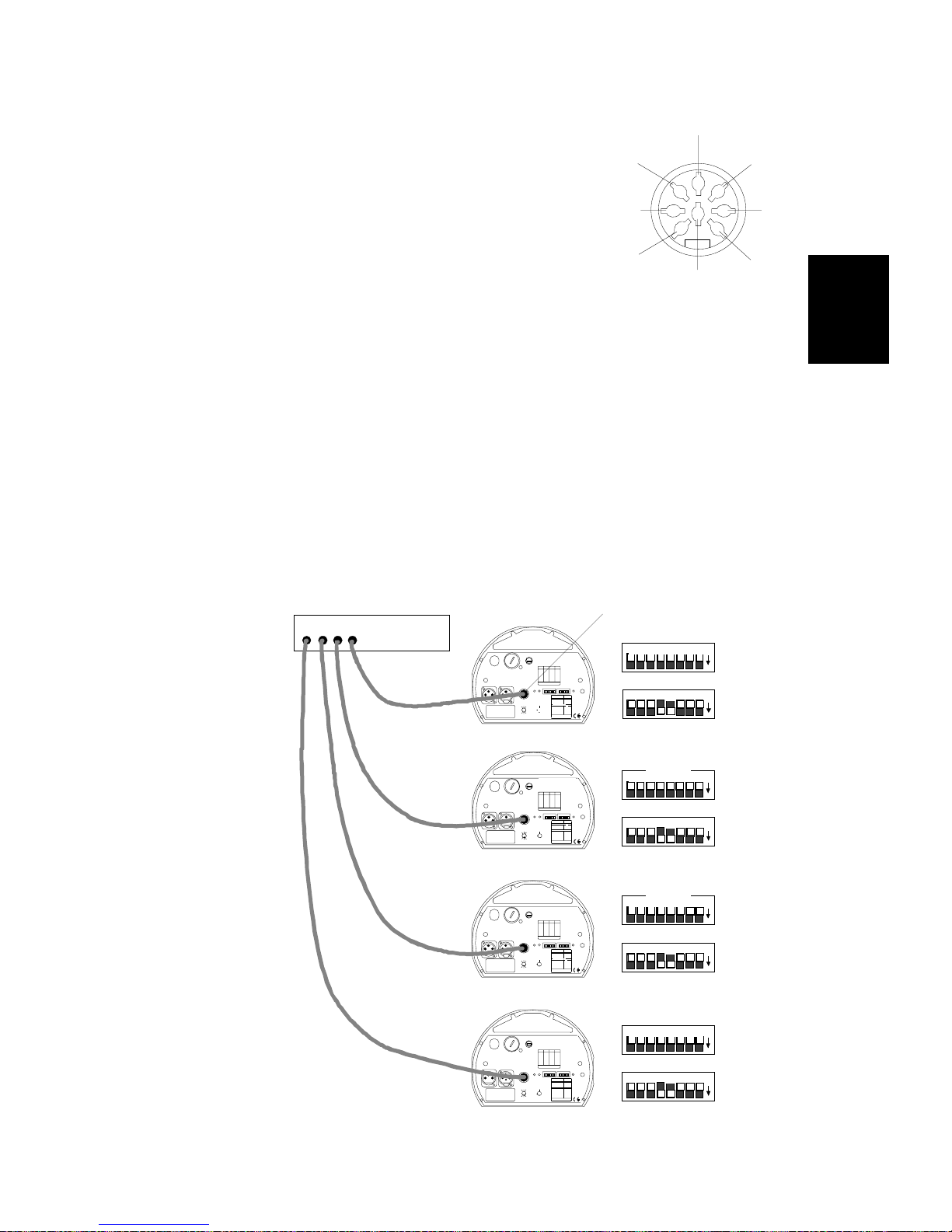
Standard Analog
Figure 2-9. Analog
1
3
5
6
7
4
2
8
0-10V Analog
GND
color
pan
dim
shutter
gobo
Mspeed
tilt
Under standard analog control, Trackspot
uses either six or seven analog channels per
fixture. The Analog In connector on the rear
panel of each fixture has been c onfigured for
a spare MSpeed input on pin 1 (see Figure 2-
9). If you choose not to set MSpeed (pin 1),
the fixture will default to the fastest MSpeed.
However, if you want an MSpeed slower
than the fastest speed, you must wire a
separate line to pin 1. See Table B-2 on page
B-5 for standard analog MSpeed times.
To link Trackspot fixtures to a standa rd analog cont roller, follow the
steps listed below:
1. On all fixtures, set personality switches 4 and 5 ON and set all
address switches OFF.
2. Connect the individual analog outputs from the controller to each
fixture’s Analog In connector using 8-pin DIN connector cables
(see Figure 2-10).
2
Note: Using standard analog control, you do not need to
terminate the last fixture on the link.
Standard Analog Controller
WARNING: NOT FOR RESIDENTIAL USE. TO REDUCE THE RISK OF
FIRE OR ELECT RIC SHOCK, DO NOT EXPOSE TO RAIN OR MOISTURE,
NO USER SERVICEABLE PARTS INSIDE. REFER SERVICING TO
QUALIFIED SERVICE PERSONNEL. FOR SAFE OPERATION CONSULT
USER MANUAL.
MODEL
SERIAL
FACTORY SET VAC
WATTS H Z
DATE QC
MODEL
SERIAL
FACTORY SET VAC
WATTS H Z
DATE QC
WARNING: CHANGE VOLTAGE SELECT ONLY WITH POWER REMOVED.
CAUTION: HOT REMOVE POWER BEFORE RELAMPING
WARNING: NOT FOR RESIDENTIAL USE. TO REDUCE THE RISK OF
FIRE OR ELECT RIC SHOCK, DO NOT EXPOSE TO RAIN OR MOISTURE,
NO USER SERVICEABLE PARTS INSIDE. REFER SERVICING TO
QUALIFIED SERVICE PERSONNEL. FOR SAFE OPERATION CONSULT
USER MANUAL.
DATA IN
MODEL
SERIAL
FACTORY SET VAC
WATTS H Z
DATE QC
Analog In connector
240
120
200
140
VOLTAGE SELECT
WARNING: CHANGE VOLTAGE SELECT ONLY WITH POWER REMOVED.
CAUTION: HOT REMOVE POWER BEFORE RELAMPING
DATA OUTDATA IN
fixture 1
120
200
140
VOLTAGE SELECT
WARNING: CHANGE VOLTAGE SELECT ONLY WITH POWER REMOVED.
CAUTION: HOT REMOVE POWER BEFORE RELAMPING
WARNING: NOT FOR RESIDENTIAL USE. TO REDUCE THE RISK OF
FIRE OR ELECTRIC SHOCK, DO NOT EXPOSE TO RAIN OR MOISTURE,
NO USER SERVICEABLE PARTS INSIDE. REFER SERVICING TO
QUALIFIED SERVICE PERSONNEL. FOR SAFE OPERATION CONSULT
USER MANUAL.
DATA OUTDATA IN
fixture 2
120
200
140
VOLTAGE SELECT
DATA OUT
fixture 3
100
220
FUSE
ANALOG IN
0-10V
ANALOG
GND
TILT
COLOR
5
42
3761
MSPEED
PAN
8
GOBO DIM
SHUTTER
240
100
220
FUSE
ANALOG IN
0-10V
ANALOG
GND
TILT
COLOR
2
5
4
3761
MSPEED
PAN
8
GOBO DIM
SHUTTER
240
100
220
FUSE
ANALOG IN
0-10V
ANALOG
GND
TILT
COLOR
5
42
MSPEED
3761
PAN
8
GOBO DIM
SHUTTER
trackspot
LIGHTWAVE RESEARCH
2209 WEST BRAKER LANE, AUSTIN, TEXAS U.S.A.
SWITCHESONSWITCHESADDRESS AD DRESS
ON
none01
102
203
1,204
305
1,306
2,307
1,2,308
409
1,410
2,411
1,2,412
FOR FURTHER INFORMATION
PLEASE CONSULT USER MANUAL
ADDRESSENABLEFAN
SPECIAL ANALOG
INPUT
GND
2
4
5
24 VDC
1
3
OUT
8
6 7
(UNREG.)
FOR FUTHER INFORMATION
CONSULT USERS MANUAL
trackspot
LIGHTWAVE RESEARCH
2209 WEST BRAKER LANE, AUSTIN, TEXAS U.S.A.
SWITCHESONSWITCHESADDRESS ADDRESS
ON
none01
102
203
1,204
305
1,306
2,307
1,2,308
409
1,410
2,411
1,2,412
FOR FURTHER INFORMATION
PLEASE CONSULT USER MANUAL
SPECIAL ANALOG
INPUT
GND
2
24 VDC
4
5
1
3
OUT
8
6 7
(UNREG.)
FOR FUTHER INFORMATION
CONSULT USERS MANUAL
trackspot
LIGHTWAVE RESEARCH
2209 WEST BRAKER LANE, AUSTIN, TEXAS U.S.A.
SWITCHESONSWITCHESADDRESS AD DRESS
ON
none01
102
203
1,204
305
1,306
2,307
1,2,308
409
1,410
2,411
1,2,412
FOR FURTHER INFORMATION
PLEASE CONSULT USER MANUAL
ENABL EFA N
SPECIAL ANALOG
INPUT
GND
2
4
5
24 VDC
OUT
1
3
8
6 7
(UNREG.)
FOR FUTHER INFORMATION
CONSULT USERS MANUAL
PERSONALITY SWITCHES
FIXTURE MODE SWITCHES 1-2
NORMAL RUN
SELF TEST
SET-UP
LAMP SAVE
CONTROL MODE SWITCHES 3-8
LIGHTWAVE CONTROL
DMX 1-256
DMX 257-512
ANALOG
AUDIO (SLAVE)
AUDIO (MASTER)
PAN INVERT
TILT INVERT
PLEASE CONSULT USER MANUAL
PERSONALITY SW ITCHES
FIXTURE MODE SWITCHES 1-2
NORMAL RUN
SELF TEST
SET-UP
LAMP SAVE
CONTROL MODE SWITCHES 3-8
LIGHTWAVE CONTROL
DMX 1-256
DMX 257-512
ANALOG
AUDIO (SLAVE)
AUDIO (MASTER)
PAN INVERT
TILT INVERT
PLEASE CONSULT USER MANUAL
PERSONALITY SWITCHES
FIXTURE MODE SWITCHES 1-2
NORMAL RUN
SELF TEST
SET-UP
LAMP SAVE
CONTROL MODE SWITCHES 3-8
LIGHTWAVE CONTROL
DMX 1-256
DMX 257-512
ANALOG
AUDIO (SLAVE)
AUDIO (MASTER)
PAN INVERT
TILT INVERT
PLEASE CO NSULT USER MANUAL
®
3,413
1,3,414
2,3,415
1,2,3,416
517
1,518
2,519
1,2,520
3,521
1,3,522
2,3,523
1,2,3,524
PERSONA LITY
AUDIO MIC
ON
NONE
1
2
1,2
NONE
5
4
4,5
3
8
6
7
FOR FURTHER INFORMATION
®
3,413
1,3,414
2,3,415
1,2,3,416
517
1,518
2,519
1,2,520
3,521
1,3,522
2,3,523
1,2,3,524
AUDIO MICPERSO NALITYAD DRESSENABLEFAN
ON
NONE
1
2
1,2
NONE
5
4
4,5
3
8
6
7
FOR FURTHER INFORMATION
®
3,413
1,3,414
2,3,415
1,2,3,416
517
1,518
2,519
1,2,520
3,521
1,3,522
2,3,523
1,2,3,524
MICPE RSONALI TYADDRESS
AUDIO
ON
NONE
1
2
1,2
NONE
5
4
4,5
3
8
6
7
FOR FURTHER INFORMATION
ADDRESS
8 7 6 5 4 3 2 1
PERSONALITY
8 7 6 5 4 3 2 1
ADDRESS
8 7 6 5 4 3 2 1
PERSONALITY
8 7 6 5 4 3 2 1
ADDRESS
8 7 6 5 4 3 2 1
PERSONALITY
8 7 6 5 4 3 2 1
on
on
on
on
on
on
Figure 2-10. Linking fixtures to a standard analog controller
Trackspot User Manua l
WARNING: CHANGE VOLTAGE SELECT ONLY WITH POWER REMOVED.
CAUTION: HOT REMOVE POWER BEFORE RELAMPING
WARNING: NOT FOR RESIDENTIAL USE. TO REDUCE THE RISK OF
FIRE OR ELECT RIC SHOCK, DO NOT EXPOSE TO RAIN OR MOISTURE,
NO USER SERVICEABLE PARTS INSIDE. REFER SERVICING TO
QUALIFIED SERVICE PERSONNEL. FOR SAFE OPERATION CONSULT
USER MANUAL.
MODEL
SERIAL
FACTORY SET VAC
WATTS H Z
DATE QC
240
120
100
200
220
140
FUSE
VOLTAGE SELECT
DATA OUTDATA IN
ANALOG IN
0-10V
ANALOG
GND
TILT
COLOR
2
24 VDC
5
4
3761
MSPEED
PAN
OUT
8
(UNREG.)
GOBO DIM
FOR FUTHER INFORMATION
SHUTTER
fixture 4
trackspot
LIGHTWAVE RESEARCH
2209 WEST BRAKER LANE, AUSTIN, TEXAS U.S.A.
SWITCHESONSWITCHESADDRESS ADDRESS
ON
none01
102
203
1,204
305
1,306
2,307
1,2,308
409
1,410
2,411
1,2,412
FOR FURTHER INFORMATION
PLEASE CONSULT USER MANUAL
NORMAL RUN
SELF TEST
SET-UP
SPECIAL ANALOG
LAMP SAVE
INPUT
GND
LIGHTWAVE CONTROL
DMX 1-256
DMX 257-512
2
4
5
ANALOG
1673
8
AUDIO (SLAVE)
AUDIO (MASTER)
PAN INVERT
TILT INVERT
CONSULT USERS MANUAL
ADDRESS
8 7 6 5 4 3 2 1
PERSONALITY
8 7 6 5 4 3 2 1
3,413
1,3,414
2,3,415
1,2,3,416
517
1,518
2,519
1,2,520
3,521
1,3,522
2,3,523
1,2,3,524
PERSONALITY SWITCHES
FIXTURE MODE SWITCHES 1-2
CONTROL MODE SWITCHES 3-8
FOR FURTHER INFORMATION
PLEASE CO NSULT USER MANUAL
®
AUDIO MICPERSO NALITYADDRESSENAB LEFAN
ON
NONE
1
2
1,2
NONE
5
4
4,5
3
8
6
7
Linking the Fixtures
on
on
2-15
Page 38
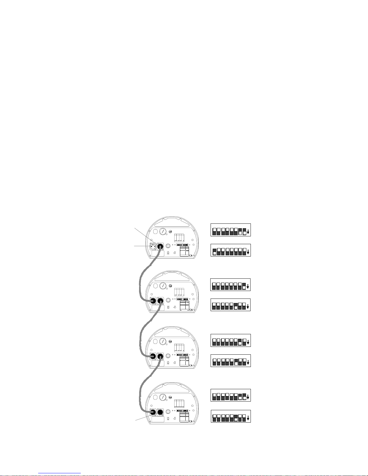
Stand Alone Operation (Master/Slave)
To link Trackspot fixtures in a master/slave configuration, follow the
steps listed below:
1. On the designated master fixture, set personality switch 8 ON and
set the address switches to equal the total number of Trackspot
fixtures (inc l u din g th e ma s t e r) . See Table C-2 on pa g e C-2 for
address switch settings.
2. On all slave fixtures, set personality switch 3 ON and set each
slave’s address switches to the fixture’s numerical order in the
link). See Table C-2 on page C-2 for address switch settings.
3. Link the master and slave fixtures together with 3-pin XLR data
cables. Plug the male end of a data cable into the Data Out
connector on the rear panel of the master fixture. Plug the female
end of that data cable into the Data In connector of the first slave
fixture. Continue using this method to link the remainder of the
slave fixtures together (see Figure 2-11).
Note: For grea ter control of Trackspot’s preset programs in
master/slave mode, link a Trackspot Special Analog
controller to the master fixture’s Analog In connector.
data out
data in
terminator
240
120
100
200
trackspot
220
WARNING: CHANGE VOLT AGE S ELECT ONLY WITH POWER REMO VED.
CAUTION: HOT REMOVE POWER BEFORE RELAMPING
WARNING: NOT FOR RESIDENTIAL USE. TO REDUCE THE RISK OF
FIRE OR ELECTRIC SHOCK, DO NOT EXPOSE TO RAIN OR MOISTURE,
NO USER SERVICEABLE PARTS INSIDE. REFER SERVICING TO
QUALIFIED SERVICE PERS ONNEL. FOR SAFE OPERATION CONSULT
USER MANUAL.
MODEL
SERIAL
FACTORY SET VAC
WATTS HZ
DATE QC
140
VOLTAGE SELECT
DATA OUTDATA IN
LIGHTWAVE RESEARCH
2209 WES T BR AKER LANE, AUSTIN, TE XAS U.S. A.
SWITCHESONSWITCHESAD DRESS ADDRE SS
FUSE
ON
none01
102
203
1,204
305
1,306
2,307
1,2,308
409
1,410
2,411
1,2,412
FOR FURTHER INFORMATION
PLEASE CONSULT USER MANUAL
ANALOG IN
SPECIAL ANALOG
0-10V
INPUT
ANALOG
GND
GND
TILT
COLOR
2
2
24 VDC
4
5
5
4
1
3
3761
OUT
MSPEED
PAN
8
8
6 7
(UNREG.)
GOBO DIM
FOR FUTHER INFORMATION
SHUTTER
CONSULT USERS MANUAL
master fixture
240
120
100
200
trackspot
220
WARNING: CHANGE VOLT AGE S ELECT ONLY WITH POWER REMO VED.
CAUTION: HOT REMOVE POWER BEFORE RELAMPING
WARNING: NOT FOR RESIDENTIAL USE. TO REDUCE THE RISK OF
FIRE OR ELECTRIC SHOCK, DO NOT EXPOSE TO RAIN OR MOISTURE,
NO USER SERVICEABLE PARTS INSIDE. REFER SERVICING TO
QUALIFIED SERVICE PERS ONNEL. FOR SAFE OPERATION CONSULT
USER MANUAL.
MODEL
SERIAL
FACTORY SET VAC
WATTS HZ
DATE QC
140
VOLTAGE SELECT
DATA OUTDATA IN
LIGHTWAVE RE SEARCH
2209 WES T BR AKER LANE, AUSTIN, TE XAS U.S. A.
SWITCHESONSWITCHESAD DRESS ADDRE SS
FUSE
ON
none01
102
203
1,204
305
1,306
2,307
1,2,308
409
1,410
2,411
1,2,412
FOR FURTHER INFORMATION
PLEASE CONSULT USER MANUAL
ANALOG IN
ADDRESSENABLEFAN
SPECIAL ANALOG
0-10V
INPUT
ANALOG
GND
GND
TILT
COLOR
2
2
4
5
5
4
24 VDC
1
3
3761
OUT
MSPEED
PAN
8
8
6 7
(UNREG.)
GOBO DIM
FOR FUTHER INFORMATION
SHUTTER
CONSULT USERS MANUAL
slave 1
240
120
100
200
trackspot
220
WARNING: CHANGE VOLT AGE S ELECT ONLY WITH POWER REMO VED.
CAUTION: HOT REMOVE POWER BEFORE RELAMPING
WARNING: NOT FOR RESI DENTIAL USE. TO REDUCE THE RISK OF
FIRE OR ELECTRIC SHOCK, DO NOT EXPOSE TO RAIN OR MOISTURE,
NO USER SERV ICEABLE PARTS INSIDE. REFER SERVICING TO
QUALIFIED SERVICE PERSONNEL. FOR SAFE OPERATION CONSULT
USER MANUAL.
MODEL
SERIAL
FACTORY SET VAC
WATTS HZ
DATE QC
140
VOLTAGE SELECT
DATA OUTDATA IN
LIGHTWAVE RESEARCH
2209 WES T BR AKER LANE, AUSTIN, TE XAS U.S. A.
SWITCHESONSWITCHESAD DRESS ADD RESS
FUSE
ON
none01
102
203
1,204
305
1,306
2,307
1,2,308
409
1,410
2,411
1,2,412
FOR FURTHER INFORMATION
PLEASE CONSULT USER MANUAL
ANALOG IN
SPECIAL ANALOG
0-10V
INPUT
ANALOG
GND
GND
TILT
COLOR
2
2
24 VDC
4
5
5
4
1
3
3761
OUT
MSPEED
PAN
8
8
6 7
(UNREG.)
GOBO DIM
FOR FUTHER INFORMATION
SHUTTER
CONSULT USERS MANUAL
slave 2
240
120
100
200
trackspot
220
WARNING: CHANGE VOLT AGE S ELECT ONLY WITH POWER REMO VED.
CAUTION: HOT REMOVE POWER BEFORE RELAMPING
WARNING: NOT FOR RESI DENTIAL USE. TO REDUCE THE RISK OF
FIRE OR ELECTRIC SHOCK, DO NOT EXPOSE TO RAIN OR MOISTURE,
NO USER SERV ICEABLE PARTS INSIDE. REFER SERVICING TO
QUALIFIED SERVICE PERSONNEL. FOR SAFE OPERATION CONSULT
USER MANUAL.
DATA IN
MODEL
SERIAL
FACTORY SET VAC
WATTS HZ
DATE QC
140
VOLTAGE SELECT
DATA OUT
LIGHTWAVE RESEARCH
2209 WEST BRAKER LANE, AUSTIN, TE XAS U.S.A.
SWITCHESONSWITCHESAD DRESS ADD RESS
FUSE
ON
none01
102
203
1,204
305
1,306
2,307
1,2,308
409
1,410
2,411
1,2,412
FOR FURTHER INFORMATION
PLEASE CONSULT USER MANUAL
ANALOG IN
ENABLEFAN
SPECIAL ANALOG
0-10V
INPUT
ANALOG
GND
GND
TILT
COLOR
2
2
24 VDC
4
5
5
4
1673
3761
OUT
MSPEED
PAN
8
8
(UNREG.)
GOBO DIM
FOR FUTHER INFORMATION
SHUTTER
CONSULT USERS MANUAL
slave 3
3,413
1,3,414
2,3,415
1,2,3,416
517
1,518
2,519
1,2,520
3,521
1,3,522
2,3,523
1,2,3,524
PERSONALITY SW ITCHES
FIXTUR E MO DE SWITCHES 1-2
NORMAL RUN
SELF TEST
SET-UP
LAMP SAVE
CONTROL MODE SWITCHE S 3- 8
LIGHTWAVE CONTR OL
DMX 1-256
DMX 257-512
ANALOG
AUDIO (SLAVE)
AUDIO (MAST ER)
PAN INVERT
TILT INVERT
FOR FURTHER INFORMATION
PLEASE CONSULT USER MANUAL
PERSONALITY SW ITCHES
FIXTUR E MO DE SWITCHES 1-2
NORMAL RUN
SELF TEST
SET-UP
LAMP SAVE
CONTROL MODE SWITCHES 3-8
LIGHTWAVE CONTR OL
DMX 1-256
DMX 257-512
ANALOG
AUDIO (SLAVE)
AUDIO (MAST ER)
PAN INVERT
TILT INVERT
FOR FURTHER INFORMATION
PLEASE CONSULT USER MANUAL
3,413
1,3,414
2,3,415
1,2,3,416
517
1,518
2,519
1,2,520
3,521
1,3,522
2,3,523
1,2,3,524
PERSONALITY SW ITCHES
FIXTUR E MODE SWITCHES 1-2
NORMAL RUN
SELF TEST
SET-UP
LAMP SAVE
CONTROL MODE SWITCHE S 3- 8
LIGHT W AV E CO N T R OL
DMX 1-256
DMX 257-512
ANALOG
AUDIO (SLAVE)
AUDIO (MASTER)
PAN INVERT
TILT INVERT
FOR FURTHER INFORMATION
PLEASE CONSULT USER MANUAL
3,413
1,3,414
2,3,415
1,2,3,416
517
1,518
2,519
1,2,520
3,521
1,3,522
2,3,523
1,2,3,524
PERSONALITY SWITCHES
FIXTUR E MODE SWITCHES 1-2
NORMAL RUN
SELF TEST
SET-UP
LAMP SAVE
CONTROL MODE SWITCHE S 3- 8
LIGHT W AV E CO N T R OL
DMX 1-256
DMX 257-512
ANALOG
AUDIO (SLAVE)
AUDIO (MASTER)
PAN INVERT
TILT INVERT
FOR FURTHER INFORMATION
PLEASE CONSULT USER MANUAL
ADDRESS
®
AUDIO MICPERSONALITYADDR ESSENABLEFAN
ON
NONE
1
2
1,2
NONE
5
4
4,5
3
8
6
7
8 7 6 5 4 3 2 1
PERSONALITY
8 7 6 5 4 3 2 1
on
on
ADDRESS
®
3,413
1,3,414
2,3,415
1,2,3,416
517
1,518
2,519
1,2,520
3,521
1,3,522
2,3,523
1,2,3,524
PERSONALITY
AUDIO MIC
ON
NONE
1
2
1,2
NONE
5
4
4,5
3
8
6
7
8 7 6 5 4 3 2 1
PERSONALITY
8 7 6 5 4 3 2 1
on
on
ADDRESS
®
AUDIO MICPERSONALITYAD DRESSENABLEFAN
ON
NONE
1
2
1,2
NONE
5
4
4,5
3
8
6
7
8 7 6 5 4 3 2 1
PERSONALITY
8 7 6 5 4 3 2 1
on
on
ADDRESS
®
MICPERSONALITYADDRESS
AUDIO
ON
NONE
1
2
1,2
NONE
5
4
4,5
3
8
6
7
8 7 6 5 4 3 2 1
PERSONALITY
8 7 6 5 4 3 2 1
on
on
Figure 2-11. Linking master and slave fixtures together
2-16
Linking the Fixtures
Trackspot User Manual
Page 39
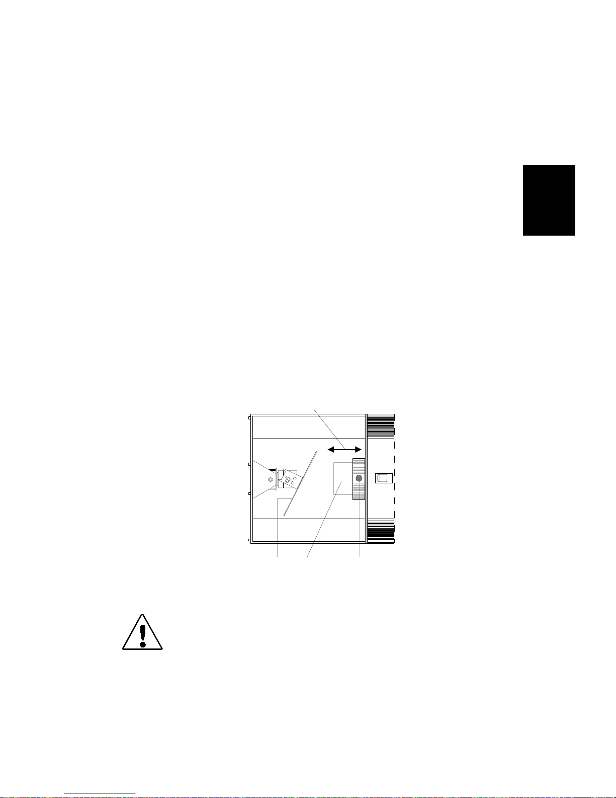
Focusing the Fixture
Once you have mounted and linked the fixtures together, you must
focus each fixture. Trackspot has a manual focus which cannot be
adjusted by a controller.
To focus the fixture:
1. Place the fixture in setup (focus) mode by setting personality
switch 2 ON.
2. Power up the fixture. The fixture performs its homing operation
and turns on the lamp. (During the homing operation you will hear
clattering sounds as the wheels, shutter, and mirror seek their
home position.)
3. Manually swivel the mirror until the beam is pointed at a flat
surface you intend to illuminate.
4. Toggle address switch 1 ON and OFF to select a gobo pattern that
helps you clearly see the effects of your focusing adjustments.
5. Loosen the lens adjustment thumbscrew and carefully slide the
lens tube in and out while watching the beam projected on the flat
surface (see Figure 2-12). When the beam has a sharp edge,
tighten the thumbscrew to secure the lens tube in place.
2
slide lens tube in and out
mirror
Figure 2-12. Lens tube adjustment
Caution: You must tighten the lens adjustment
thumbscrew firmly. The lens tube may fall
from the fixture if it is not secured.
lens
tube
lens adjustment
thumbscrew
Trackspot User Manua l
Focusing the Fixture
2-17
Page 40

2-18 Trackspot User Manual
Page 41
Chapter 3
General Maintenance
This section includes information on replacing parts, installing custom
gobos, and cleaning your fixture.
Caution: This fixture must be serviced by qualified
personnel. The information listed in this
section is intended to assist qualified
personnel only.
Replacing Parts
This section explains how to remov e and re place parts inside the
fixture. Please note the warnings under each heading before se rv icing
your fixture.
Replacing the Lamp
3
You will need:
• Philips
• protective eye w ear
• leather gloves
• isopropyl alcohol wipe(s)
To replace the lamp:
®
QT 8500 250 W lamp (p/n 550 30036)
Caution: This equipment is designed for use with a
Philips
other type of lamp may be hazardous and may
void the warranty.
Warning: An operating, unshielded QT 8500 lamp emits
ultraviolet and visible (UV-vis) radiation
which could damage eyes and skin. Whenever
you are working on or near an exposed QT
8500 lamp, wear protective eye gear. Never
look directly at the lamp while the lamp is on.
®
QT 8500 250 W lamp only. Use of any
1. Unplug the fixture. If the fixture has been operating, wait at least 5
minutes for the lamp to cool before handling.
2. Put on your protective eyewear and leather gloves.
3. Turn the fixture over so you can easily acce ss its underside.
Trackspot User Manua l
Replacing Parts
3-1
Page 42
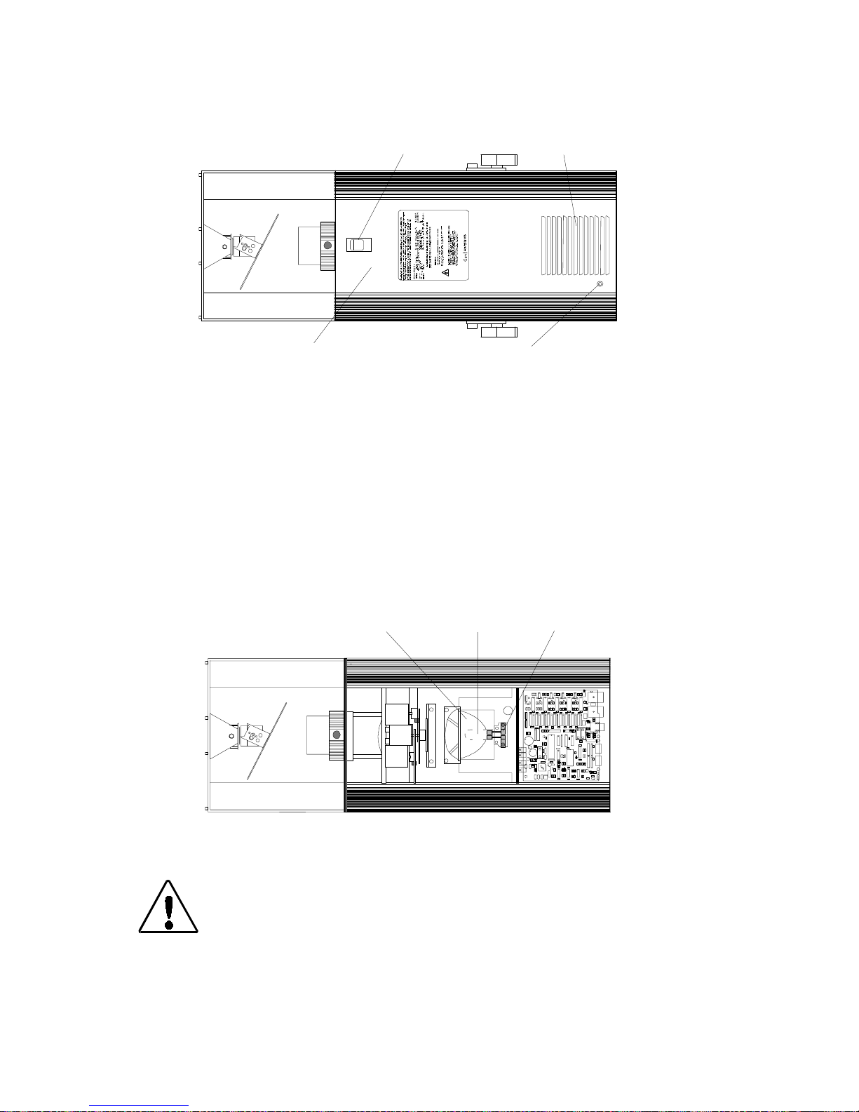
4. Remove the fixture’s access door by sliding the thumb latch towar d
the rear of the fixture and lifting the door off (see Figure 3-1).
thumb latch
cooling fan intake
access door
safety cable connection point
on inside surface
Figure 3-1. Underside of Trackspot
The access door is connected to the fixture by a safety cable. You
can leave the door attached, or you can unclip the safety cables to
completely remove the door from the fixture.
5. Locate the reflector, lamp socket, and old QT 8500 lamp (see
Figure 3-2). To remove the existing QT 8500 lamp, re ach inside the
reflector and carefully pull the lamp s traight out of the socket. Lift
the old lamp out of the reflector and discard.
reflector
QT 8500 lamp
socket
Figure 3-2. Underside of Trackspot with access door removed
Caution: Do not squeeze the lamp glass when removing
3-2
Replacing Parts
the old lamp from the socket. Lamp glass may
shatter.
Trackspot User Manual
Page 43
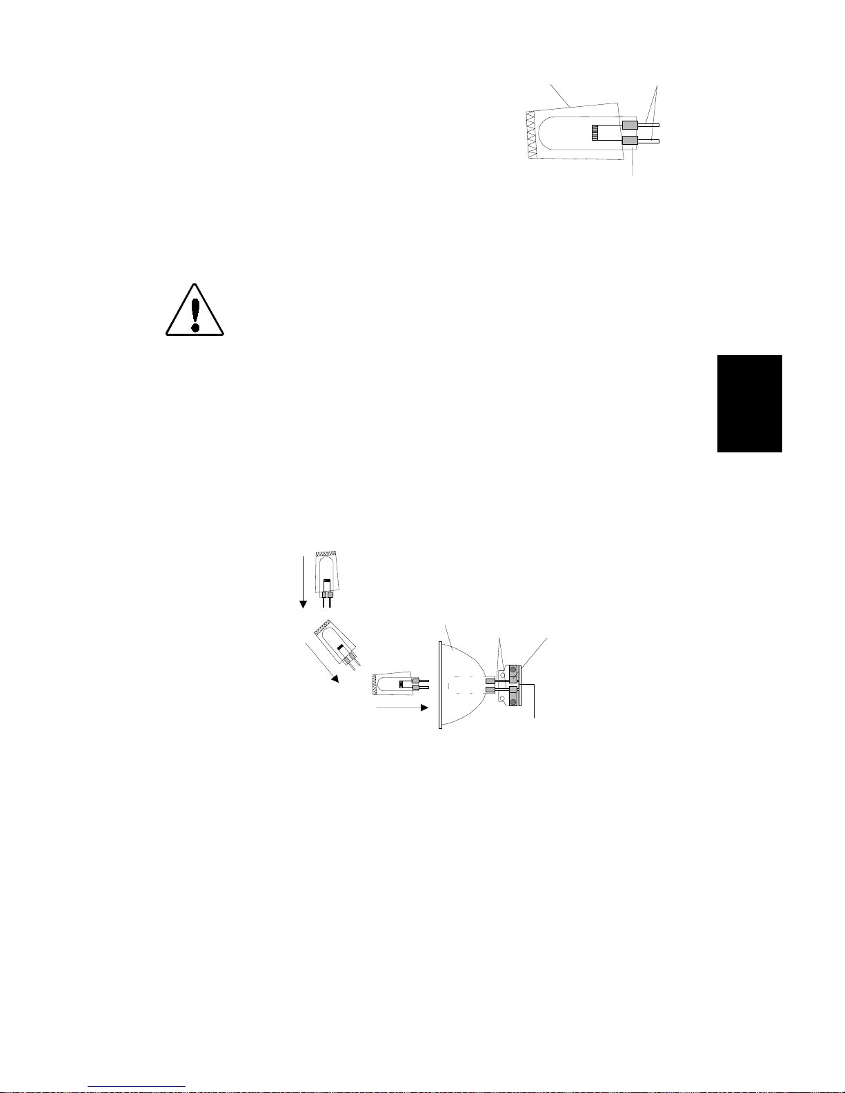
6. Open the QT 8500 lamp box and
Figure 3-3. Proper way to
handle a QT 8500 lamp
QT-8500 lamp
plastic wrapper
base pins
remove the lamp in its plastic
wrapper. Carefully open the end of
the wrapper so that only the two
lamp base pins are exposed (see
Figure 3-3). Hold the lamp within its
wrapper to avoid touching the lamp
glass. If you accidently touch the
lamp glass, clean it with a n isopropyl
alcohol wipe.
Caution: When ha ndl ing the QT 8500 lamp, avoid
contact with the lamp glass. If the lamp glass
is soiled by oil or dirt from skin, gloves, etc.,
clean the cold lamp glass with an alcohol
wipe. A soiled lamp could overheat and burst,
causing damage to the fixture.
7. Holding the lamp by its wrapper, insert the lamp in the reflector
until the base pins extend through the rear opening of the reflector
(see Figure 3-4). Continue guiding the lamp until the two base pins
are firmly seated in the lamp socket and touching the ce ramic stop
(see Figure 3-4).
reflector
base
pins
lamp
socket
ceramic
stop
Figure 3-4. Installing a new lamp
Remove and discard the plastic wrapper. You do not need to optimize
the lamp because the Trackspot fixture uses a self-aligning lamp
socket.
3
If you disconnected the access door from the fixture, reconnect the
safety cable to the acce ss door. Replace the a cces s door and secure the
thumb latch.
Do not remove your protective eyewear or leather
gloves until the access door is in place
Trackspot User Manua l
.
Replacing Parts
3-3
Page 44
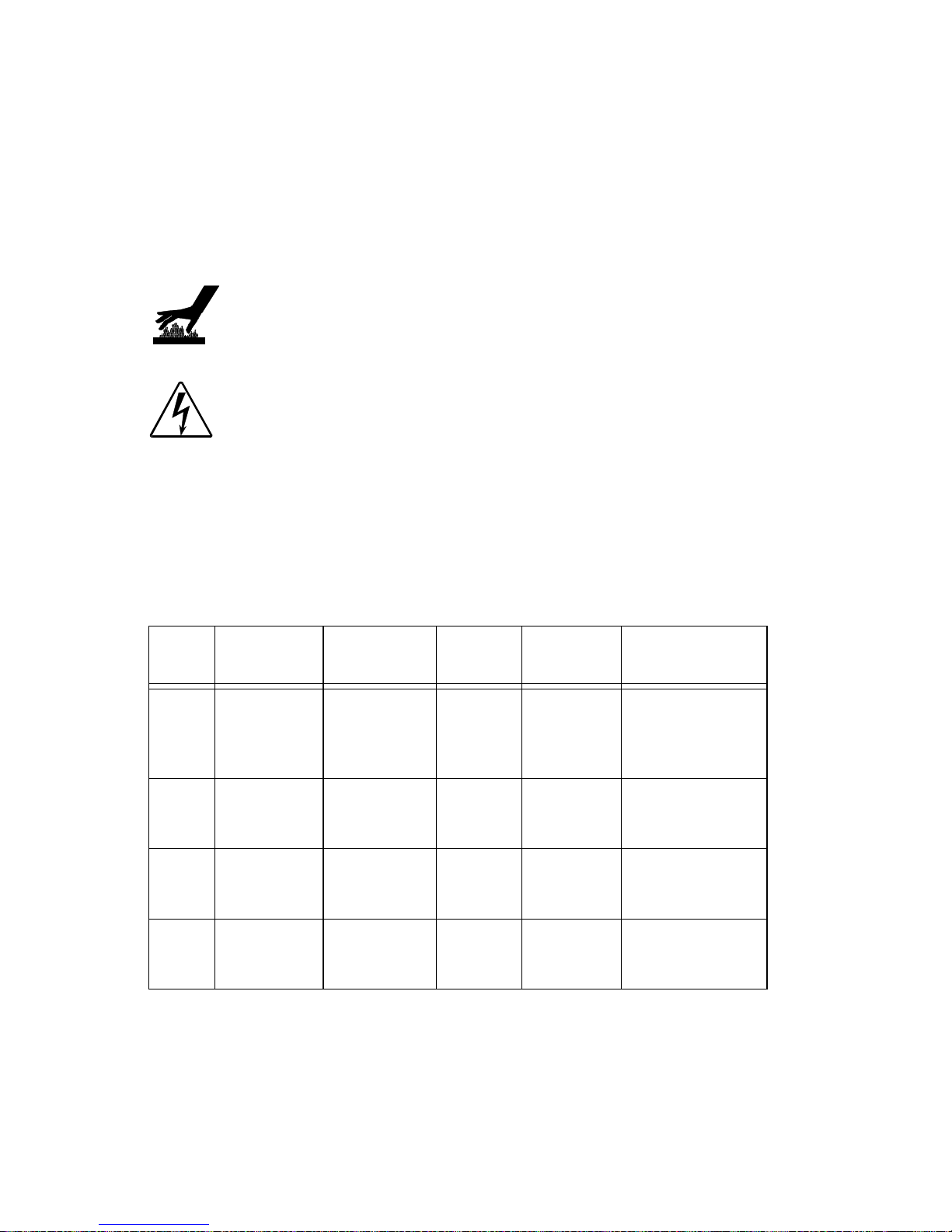
Replacing Power Supply Fuses
This section explains how to rep lace the fuses located on the T rackspot
circuit b o a rd and rear panel.
You will need:
• flat head screwdriver (to replace the rear panel fuse only)
• replacement fuse (see Table 3-1 for type and sizes)
Caution: When operating, equipment surfaces may
reach temperatures up to 67° C (153° F).
Allow 5 minutes for the fixture to cool before
handling.
Warning: Replace f uses
and rating.
To replace the fuse:
1. Unplug the fixture. If the fixture has been operating, allow t h e
fixture to cool as described above.
2. Determine which fuse(s) to replace by referring to Table 3-1 below.
Table 3-1. Description and function of Trackspot fuses
Fuse Location
F1
F2
F3
F4 rear panel
circuit
board
circuit
board
circuit
board
Type and
Rating
5.0 A, 250V,
Fast Blow
Only
.125 A,
250V, Fast
Blow Only
.125 A,
250V, Fast
Blow Only
4.0 A, 250V,
Slow Blow
Only
Size Protects Symptom
5mm x
20 mm
5mm x
20 mm
5mm x
20 mm
5mm x
20 mm
with the specified type
only
No motors work.
All Motors
Data Link
Data Link
Main
Power
Input
Yellow Enable
LED does not
light.
No response to
data link.
No response to
data link.
No power. Unit
appears dead.
3. Replace the fuse(s) with a fuse of the same type and rating.
To access the fuses on the circuit board, remove the fixture’s
access door and locate the fuse to be replaced (see Figure 3-5).
After replacing the approp riate fuse(s) , replace the fi xture’s access
door and secure the thumb latch.
3-4
Replacing Parts
Trackspot User Manual
Page 45
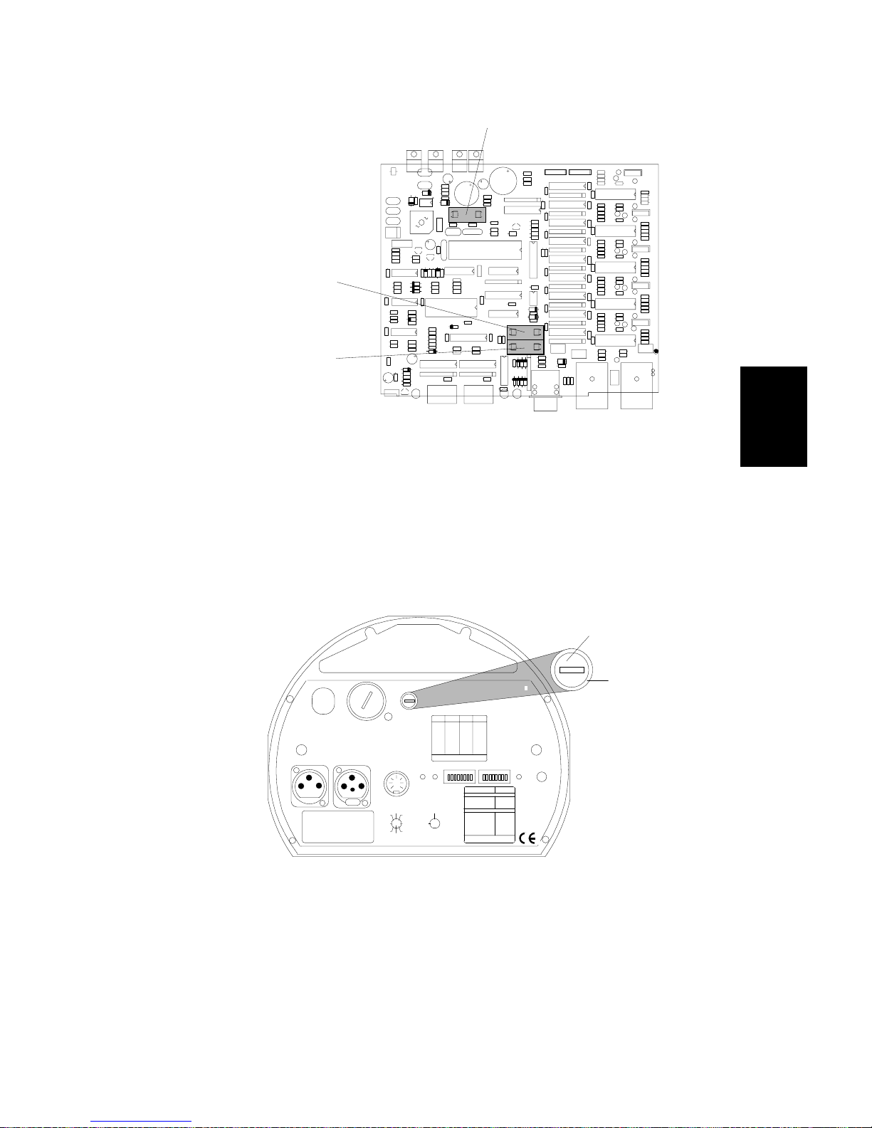
F3 Fuse
.125 A, 250 V,
Fast Blow Only
F2 Fuse
.125 A, 250 V,
Fast Blow Only
F1 Fuse
5.0 A, 250 V, Fast Blow Only
Figure 3-5. Fuse locations on the circuit board
To access the fuse on th e rear panel, locate the f use housi ng on the
rear panel (see Figure 3-6). Insert a flat head screwdriver in the
slot on the fuse housing and push in and turn until the fuse
housing pops out of the rear panel. After replacing the F4 fuse,
insert the fuse housing in the rear panel. Use the screwdriver to
push in and turn until the fuse housing is flush with the outer ring.
F4 fuse housing
outer
ring
140
VOLTAGE SELECT
WARN IN G: CH ANGE VOLTA GE SE LE CT ONLY WITH POWER REMOVED.
CAUTION: HOT REMOVE POWER BEFORE RELAMPING
WARNING: NOT FOR RESIDENTIAL USE. TO REDUCE THE RISK OF
FIRE OR ELECTRI C SHOCK , DO NOT EX POSE TO R AIN OR MOI STURE ,
NO USER SE RVI CEA B L E PART S INS IDE . REFER SERVICING TO
QUALIFIED SERVICE PERSONNEL. FOR SAFE OPERATION CONSULT
USER MANUAL.
DATA OUTDATA IN
MODEL
SERIAL
FACTORY SET VAC
WATTS HZ
DATE QC
PERSONALITY
®
MIC
AUDIO
ON
NONE
1
2
1,2
NONE
5
4
4,5
3
8
6
7
240
120
100
200
220
ANALOG IN
TILT
MSP EED
GOBO DIM
FUSE
0-10V
SPECIAL AN AL OG
ANALOG
GND
COLOR
2
5
4
24 VDC
3761
OUT
PAN
8
(UNREG.)
FOR FUTH ER INFORMATION
SHUTTER
CONSULT USERS MANUAL
trackspot
LIGHTWA VE RESEARCH
2209 WEST BRAKER LANE, AUSTIN , TEXAS U.S.A.
SWITCHESONSWITCHESADDRESS ADDRESS
ON
3,413
none01
1,3,414
102
2,3,415
203
1,2,3,416
1,204
517
305
1,518
1,306
2,519
2,307
1,2,520
1,2,308
3,521
409
1,3,522
1,410
2,3,523
2,411
1,2,3,524
1,2,412
FOR FURTHER INFORMATION
PLEASE CONSULT USER MANUAL
ADDRESS
ENABLEFAN
PERSONALITY SWITCHES
FIXT URE MODE SWITCHES 1-2
NORMAL RUN
SELF TEST
SET-UP
LAMP SAVE
INPUT
CONTROL MODE SWITCHES 3-8
GND
LIGHTWAVE CONTROL
DMX 1-256
DMX 257-51 2
2
4
5
ANALOG
1673
8
AUDIO (SLAVE)
AUDIO (MASTER )
PAN INVERT
TILT I NVERT
FOR FURTHER INFORMATION
PLEASE CONSULT USER MANUAL
3
Figure 3-6. Fuse housing location on the rear panel
Trackspot User Manua l
Replacing Parts
3-5
Page 46
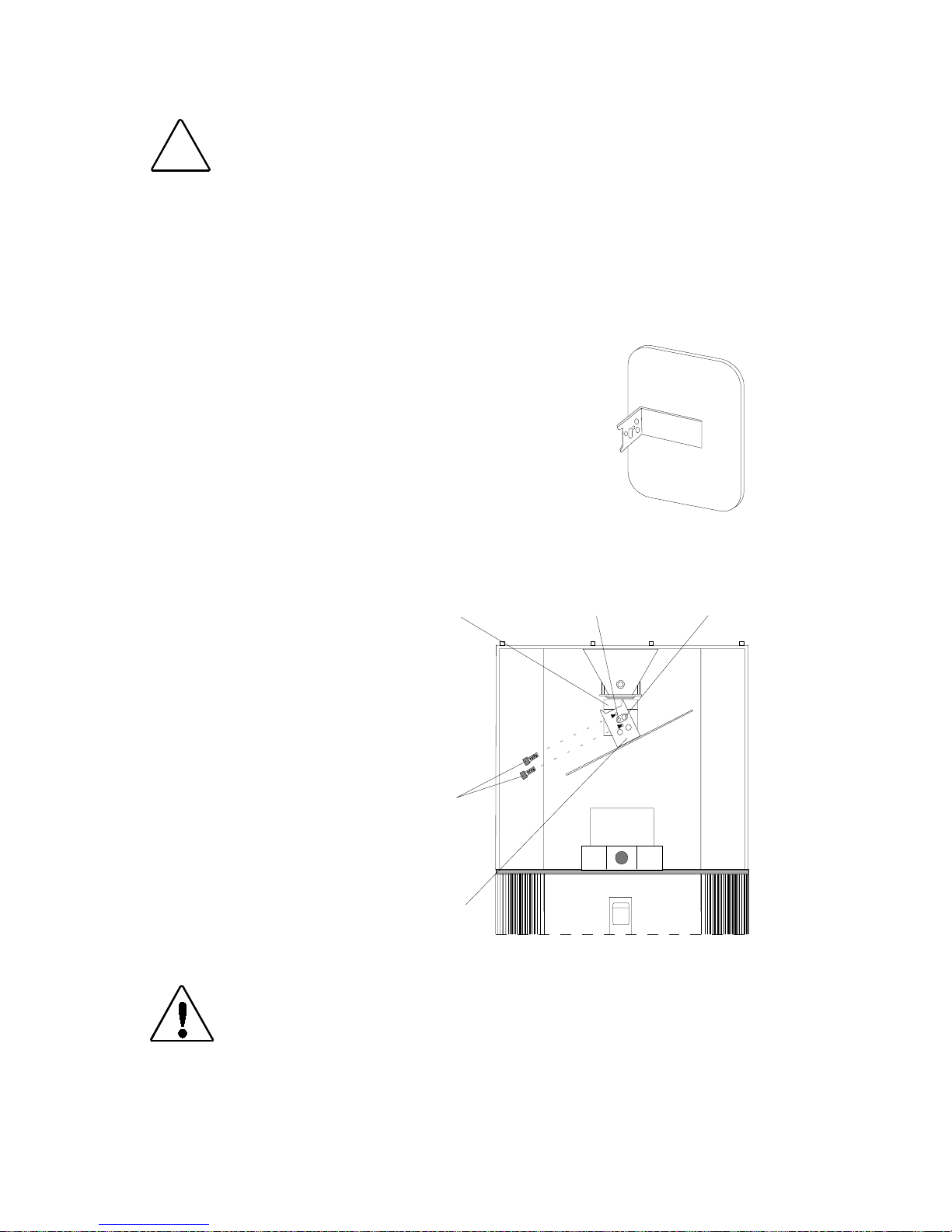
Replacing the Mirror Assembly
Figure 3-7.
Mirror assembly
Caution: Use caution when handling broken glass.
!
You will need:
• replacement mirro r assembly (p/n 80180001) (see Figure 3-7)
• leather gloves
• 7/64-inch allen wrench
To replace the mir ror assembly:
1. Unplug the fixture.
2. Put on your leather gloves.
3. Use a 7/64-inch allen wrench to remove the
two allen screws that secure the mirror
assembly to the motor (see Figure 3-8). Set
the screws aside.
Glass shards are extremely sharp.
4. Remove the old mirror assembly and carefully
discard the broken glass.
5. Open the box
containing the new
mirror and carefully
remove the mi r ror
assembly from its fo am
packaging.
6. Plac e t h e n ew mi r ror
assembly over the
spring plunger and
motor shaft. Align the
screw holes on the new
mirror assembly with
the screw holes on the
motor. Repl ace the two
allen screws. Use the
allen wrench to tighten
these screws securely.
Caution: Y ou must tighten the two allen screws firmly.
The mirror assembly may fall from the fixture
if it is not secured.
motor
allen
screws
mirror
assembly
Figure 3-8. Installing a new mirror
motor shaftspring plunger
3-6
Replacing Parts
Trackspot User Manual
Page 47
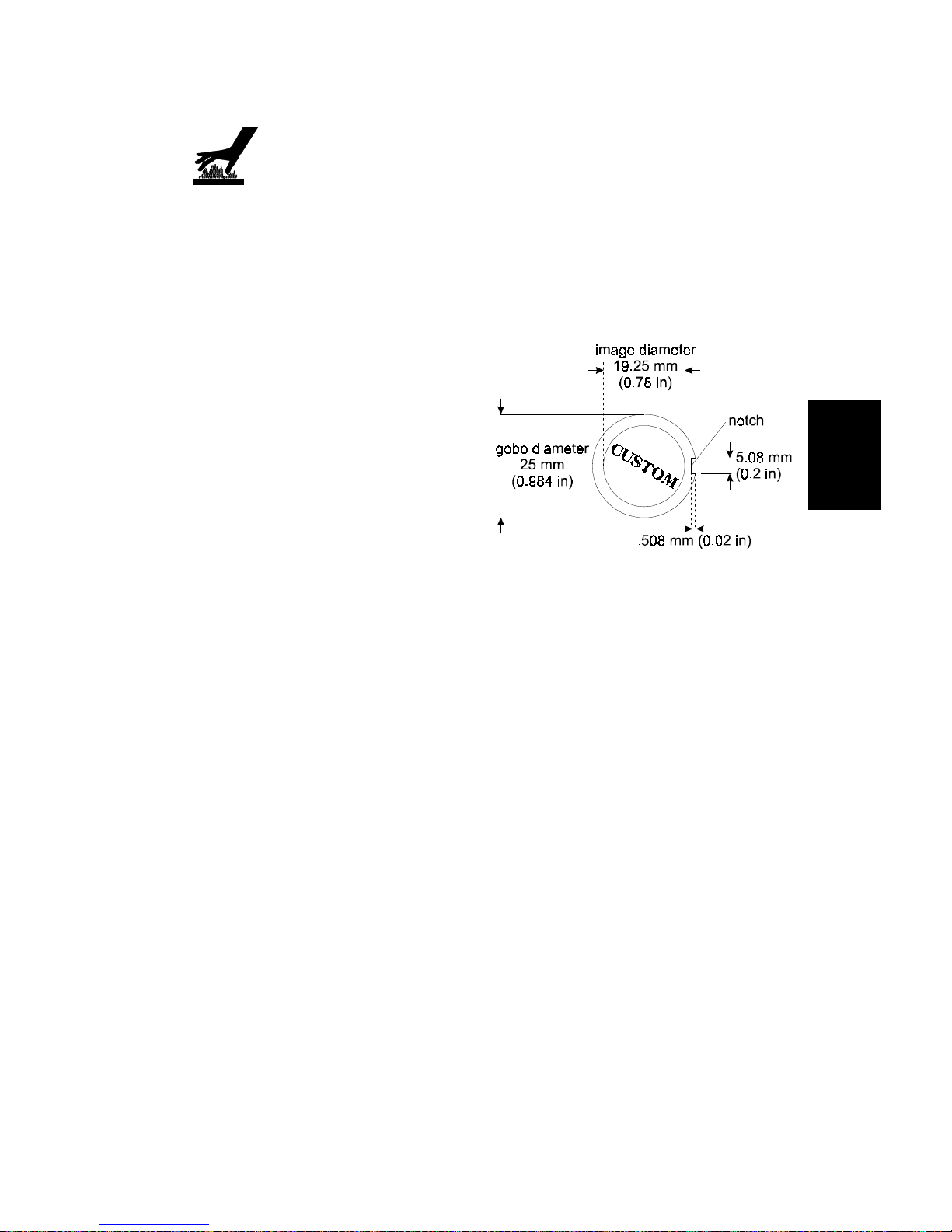
Replacing or Installing Custom Gobos
Caution: If the fixture has been operating, allow the
fixture at least 5 minutes to cool before
handling.
The Trackspot gobo wheel includes one open position for a custom
gobo patterns. This allows you to install any gobo pattern you choose.
(An optional gobo wheel with nine open positions for custom gobos
(p/n 99110017) is also available from your High End Syst ems dealer/
distributor.)
The recommended custom gobo
should be made of stainless steel
and have a single notch on the
edge for easy installation (see
Figure 3-9). The custom gobo
should be between 0.1mm (0.004
inches) and 0.3mm (0.012 inches)
thick with a diameter of 25mm
(0.984 inches).
3
To install a gobo:
1. Unplug the fixture. If the fixture has been operating, allow t h e
fixture to cool as described above.
2. Turn the fixture over so you can easily acce ss its underside.
3. Remove the fixture’s access door by sliding the thumb latch towar d
the rear of the fixture and lifting the door off.
The access door is connected to the fixture by a safety cable. You
can leave the door attached, or you can unclip the safety cables to
completely remove the door from the fixture.
4. Locate the gobo wheel and gobo wheel sensor (see Figure 3-10).
Handle the gobo wheel carefully. If you accidently bend the gobo
wheel, it may rub against and damage the sensor. If the wheel is
rubbing against the sensor or any other internal component, see
“Adjusting Wheel Clearance” on page 3-12.
Figure 3-9. Custom gobo
Trackspot User Manua l
Replacing Parts
3-7
Page 48
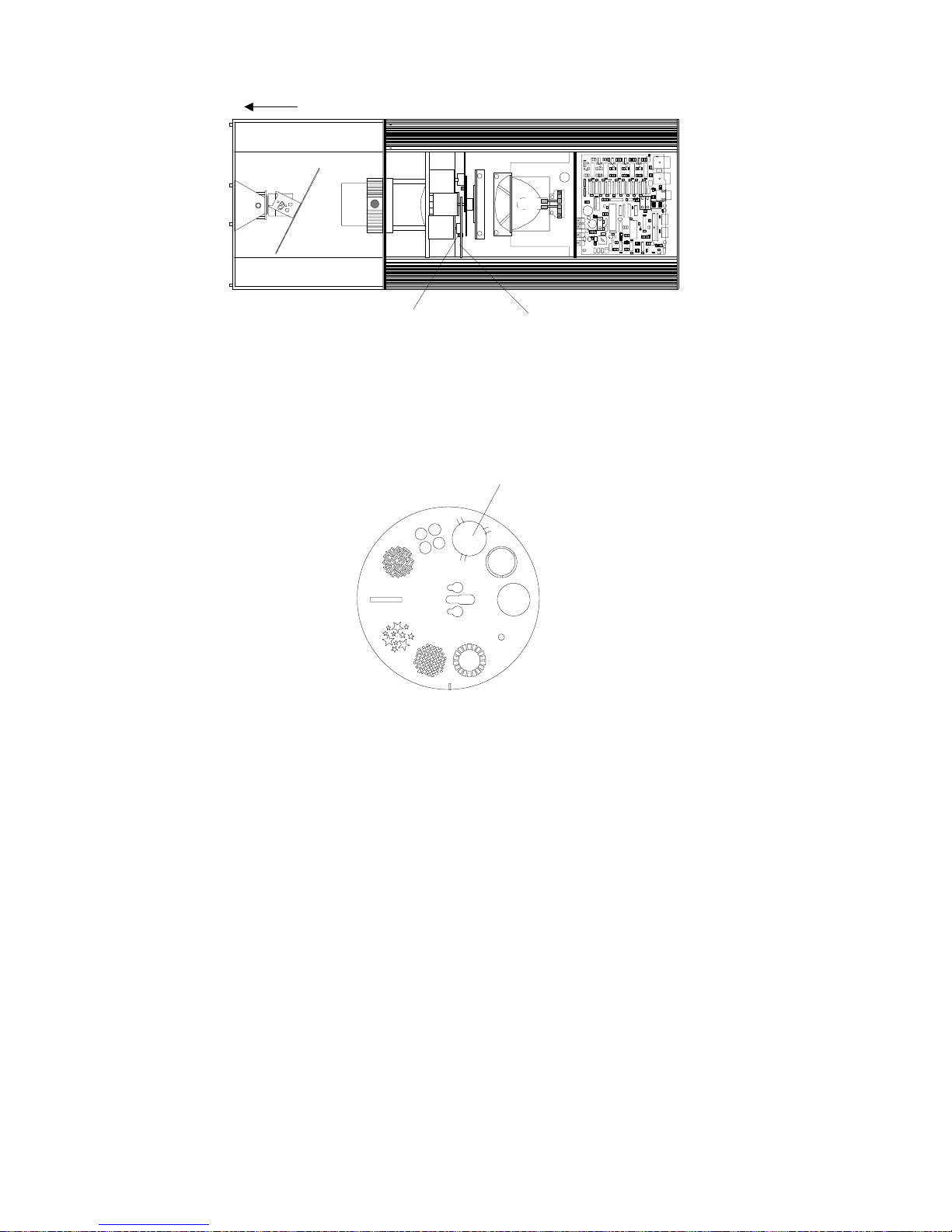
front of fix ture
gobo wheel sens or
gobo wheel
Figure 3-10. Gobo wheel and gobo wheel sensor location
5. Manually rotate the gobo wheel until the custom gobo position is at
the top of the wheel. The custom gobo position is identified by the
three tabs on the outer edge of the aperture (see Figure 3-11).
custom gobo position
Figure 3-11. Custom gobo aperture in gobo wheel
6. Carefully slide the custom gobo under two of the three tabs. If the
gobo has a notch, align the notch with the last tab, press the gobo
in place, and turn the gobo until the notch and the tab are no
longer aligned. If the gobo does not have a notch as
recommended, you must carefully apply pr essure to the free side
of the custom gobo until it bows enough to slide under the third
tab.
Note: If the custom gobo has letters or numbers, install the gobo
so that the information is legible when looking at the gobo
from the front of the fixture (see Figure 3-10).
7. Reconnect the safety cable (if applicable), replace the access door
and secure the thumb latch.
For more information about Trackspot custom gobos, contact either
your High End Systems dealer/distributor, High End System Sales, or
visit the High End Systems Web site. For contact information, see the
section titled “International Sales” on page ii.
3-8
Replacing Parts
Trackspot User Manual
Page 49
Cleaning Your Trackspot
How often you clean your Trackspot depends on the environment. If
your fixture is used in a dusty/oily environme nt, y o u should clean your
fixture once a month. A clean fixture help s m aintain performance and
reliability, since dust and dirt can accumulate and cause loss of light
output, overheating, and/or malfunctions.
Cautions: 1) If the fixture has been operating, allo w th e
fixture at least 5 minutes to cool before
handling.
®
2) Use
source (25 psi or lower)
3) To avoid personal injury, do not expose
your eyes or skin to the direct jet of
compressed air, since it can constitute a
serious health haza rd. Use suitable
protection for your eyes and exposed skin.
Warning: Unplug the fixture before cleaning.
To thoroughly clean your Trackspot, you will need:
• a soft, lint-free cotton cloth
• mild glass cleaning solution
• vacuum
• soft dusting brush or low-pressure compressed air source
•1/4-inch wrench
• cotton swab
a low-pressure compressed air
only
3
Cleaning the Outer Surfaces
Wipe the outer surface s with a soft cloth or use a vacuum to remove the
dust and dirt. Vacuum dirt from the cooling fan air vents; do not use a
blower to clean the fan, since this will force dirt into the fixture.
To clean the fixture’s lens and mirror, apply a small amount of mild
glass cleaning solution to a clean, soft cloth and gently wipe the lens
and mirror surfaces.
Note: Make sure to clean both sides of the lens glass. To access
the inside of the lens tube glass, loosen the adjustment
thumbscrew and remove the lens tube from the fixture.
See Figure 2-12 on page 2-17 to locate the lens tube and
adjustment thumbscrew.
You must refocus the fixture after removing the lens tube.
For information on focusing the fixture, see “Focusing the
Fixture” on page 2-17.
Trackspot User Manua l
Cleaning Your Trackspot®
3-9
Page 50
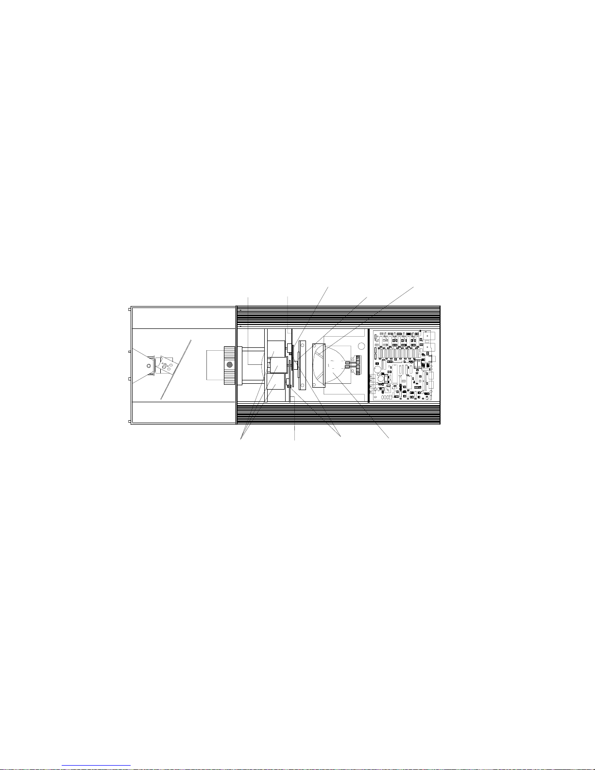
Cleaning the Internal Components
Remove the fixture’s access door by sliding the thumb latch toward the
rear of the fixture and lifting the door off. The access door is
connected to the fixture by a safety cable. You can leave the door
attached, or you can unclip the safety cable to completely remove the
door from the fixture.
Wipe the inner surfaces with a soft cloth or use a vacuum to remove the
dust and dirt. If you use a vacuum on the fan, stabilize the fan blades
with an object (not your finger!), such as a pen or a screwdriver, to
prevent the fan from spinning (see Figure 3-12). Allowing the fan to
spin with the force of the compressed air could damage the fan.
Locate the power lens, stepper motors, gobo wheel, color wheel,
sensors, shutter, hot mirror, and reflector (see Figure 3-12).
power
lens
stepper motors
color
wheel
gobo wheel
shutter
hot
mirror
sensors
fan
reflector
Figure 3-12. Trackspot internal components
Clean the stepper motors, shu t ter, and reflector with a soft dusting
brush or low-pressure compressed air source to remove accum u lated
dirt and dust.
Clean the hot mirror and power lens with a soft cloth and mild glass
cleaning solution.
To clean the color wheel, gobo wheel, and their sensors, you must
remove each wheel from the fixture. Follow the procedures below to
remove, clean, and reinstall each wheel.
Removing the Color Wheel or Gobo Wheel
For this procedure, you will need a 1/4-inch wrench.
Note: Be careful not to scratch the dichroic filter glass on the
wheels by scraping against other objects inside the fixture.
3-10
Cleaning Your Trackspot®
Trackspot User Manual
Page 51
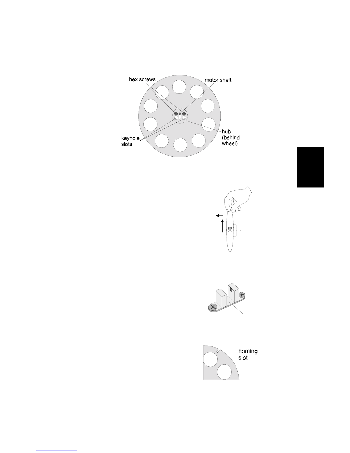
To remove either the color or gobo wheel:
groove
1. Manually rotate the wheel until the two 1/4-inch hex screws are
pointed up and the large ends of the keyhole slots are pointed
down (see Figure 3-13).
Figure 3-13. Components of the color and gobo wheels
2. Holding the wheel in
place, loosen , but do not
remove these two hex
screws using a 1/4-inch
wrench.
3
3. Pull up on the wheel to
slide the large ends o f the
keyhole slot over the hex
screw heads, and pull out
to remove the wheel (see
Figure 3-14).
Locate the sensor below the
wheel (see Figure 3-15).
Gently clean the sensor’s
groove with either a cotton
swab dipped in mild glass
cleaner or with compressed
air.
Clean the dichroic filters or
gobos on the wheel with a mild
glass cleaner and a clean, soft
cloth. Make sure the wheel’s
homing slot is free of dust and
dirt (see Figure 3-16).
Figure 3-14. Pull wheel up and out
to remove
Figure 3-15. Sensor below each wheel
Figure 3-16. Homing slot on wheel
Trackspot User Manua l
Cleaning Your Trackspot®
3-11
Page 52

Reinstalling the Color Wheel or Gobo Wheel
1. Hold the wheel so that the large end s of the keyhole slots are
pointed down and the adhesive used to hold glass to the wheel is
facing away from the lamp.
Dichroic glass is attached to both the gobo wheel a nd color wheel.
On one side of the w h eel, you can clearl y se e th e ad h es i ve used to
attach the glass. On the other side of the wheel, you see only the
glass (no adhesive).
Caution: You must replace the wheel so that the
adhesive used to hold the glass to the wheel is
facing away from the lamp, otherwise, the
heat from t he l amp could melt the ad he s i v e
and cause the glass to fall from the wheel.
2. Place the bottom of the wheel in the sensor groove. Carefully slip
the large ends of the keyhole slots over the hex screws. Push the
wheel in then down until the hex screws are in the narrow ends of
the keyhole slots.
3. Tighten the hex screws while holding the wheel in place. Tighten
the screws only until they are snug; do not overtighten.
4. Manually rotate the wheel and note any contact between t he wheel
and its sensor. If there is contact, remove the wheel and lay it on a
flat surface to determine if the wheel is warped. If the wheel is
warped, contact High End Systems customer service (see “Getting
Help” on page Intro-3). If the wheel is not warped, adjust the
wheel’s clearance to the sensor. For more inform ation, se e
“Adjusting Wheel Clearance” on page 2-12.
When you have successfully cleaned the fixture’s internal compone nts,
reconnect the safety cable (if applicable), replace the acce ss door, and
secure the thumb latch.
Adjusting Wheel Clearance
Adjust the wheel clearance to prevent either the color or gobo wheel
from making contact with its sensor or any other object in the
Trackspot fixture.
Before you adjust the wheel cleara nce, remove the wheel and l ay it on a
flat surface to determine if the wheel is warped (see “Removing the
Color Wheel or Gobo Wheel” on page 3-10.) If the wheel is warped,
contact High End Systems customer service (see “Getting Help” on
page Intro-3).
If the wheel is not warped, reinstall the wheel and follow the pr ocedure
below to adjust the wheel clearance (see “Reinstalling the Color Wheel
or Gobo Wheel” on page 3-12.)
3-12
Adjusting Wheel Clearance
Trackspot User Manual
Page 53
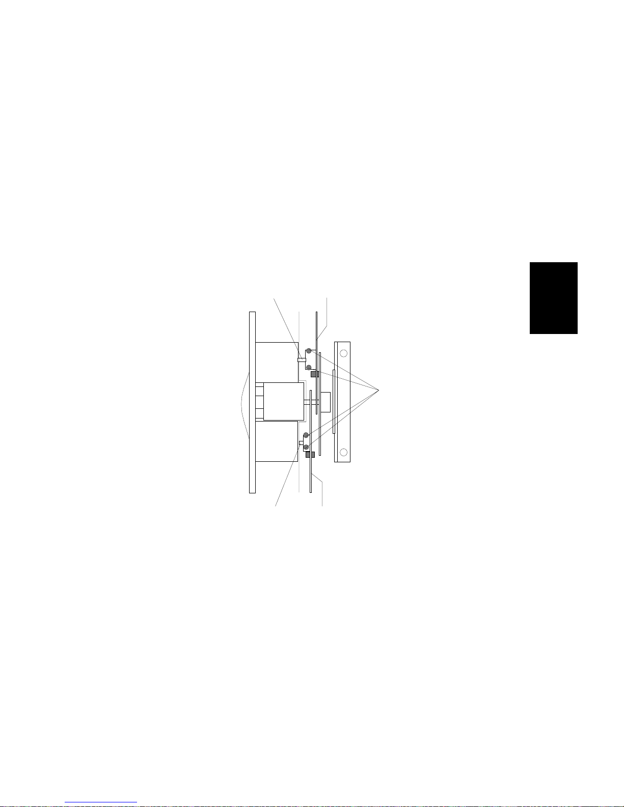
You will need:
• 7/64 inch allen wrench (preferably with a long handle)
To adjust the wheel clearance:
1. Unplug the fixture. If the fixture has been operating, allow t h e
fixture to cool for at least 5 minutes before handling.
2. Remove the fixture’s access door and locate the color and gobo
wheels (see Figure 3-17).
3. Manually rotate the whee l and note wher e the wheel contacts any
other object.
4. Loosen, but do not remove, the two al len scre ws located on the
wheel’s hub (see Figure 3-17).
motor shaft
motor shaft
Figure 3-17. Allen screws on the color wheel and gobo wheel hubs
5. Press on the center of the wheel to move the hub back and forth on
the motor shaft. Position the wheel so that it does not make
contact with its sensor or any other object as it turns.
color wheel
hub
screws
gobo wheel
3
6. Tighten the allen screws while holding the wheel in place. Tighten
the screws only until they are snug; do not overtighten.
When you have successfully adjusted the wheel clearance , re connect
the safety cable (if applicable), replace the access door, and secure the
thumb latch.
Trackspot User Manua l
Adjusting Wheel Clearance
3-13
Page 54

3-14 Trackspot User Manual
Page 55
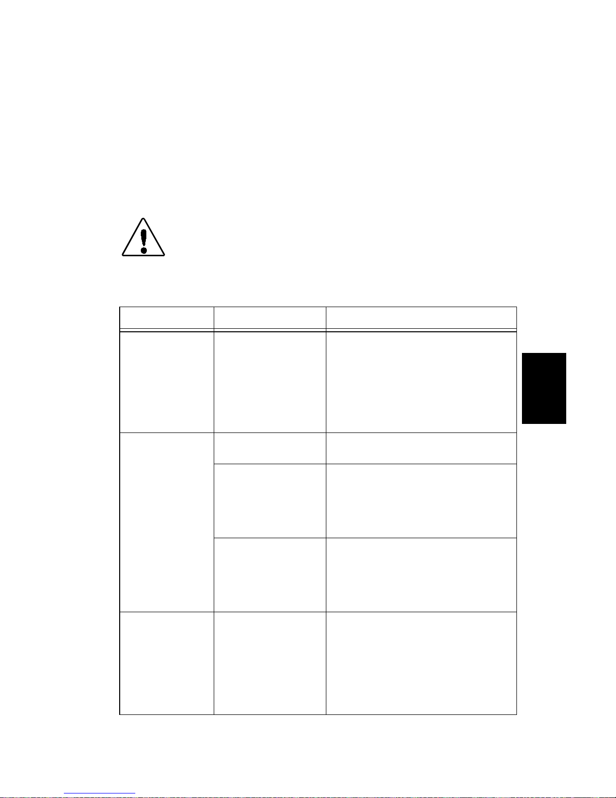
Chapter 4
Troubleshooting
This chapter lists typical symptoms and solutions for problems you
might experience when using your T rackspot. If you need additional
help, or if the problem you are experiencing is not listed in this se ction,
contact your High End Systems dealer/distributor or High End Systems
Customer Service in one of the ways shown in the section titled
“Getting Help” on page Intro-3.
Caution: This fixture must be serviced by qualified
personnel. The information listed in this
section is intended to assist qualified
personnel only.
Table 4-1. Symptoms and Solutions
Problem Possible Cause Possible Solution
Fixture does n ot
work: no LEDs,
fans, lamp, or
other
functionality
(fixture appears
dead
Lamp will not
strike
Light output is
low , be am edg e
is very soft,
images fuzzy
No input power
Bad lamp
Incorrect voltage
setting
Lamp not fully
seated in socket.
Dichroic filters,
mirror , refl ect or,
and/or lenses dirty.
a. Verify the fixt ure i s p lu gge d into
a working power supply.
b. Replace the rear panel fuse.
For more information, see
“Replacing Power Supply
Fuses” on page 3-4.
Replace lamp with new or verified
working lamp.
Make sure the fixture is set for the
same voltage as the power outlet.
For more information, see
“Selecting the Voltage” on page
1-3.
Make sure the lamp base pins are
correctly inserte d in the socket and
touch the ceramic stop. For more
information, see “Replacing the
Lamp” on page 3-1.
Clean the lens tube, mirror,
reflector, and dichroic filter glass.
For more information, see
“Cleaning the Outer Surfaces ” on
page 3-9 and “Re moving t he Co lor
Wheel or Gobo Wheel” on page
3-10.
4
Trackspot User Manua l 4-1
Page 56

Table 4-1. Symptoms and Solutions
Problem Possible Cause Possible Solution
a. Check the air vents for
restricted air flow due to dust
and dirt.
b. Clean the fan and verify the fan
is working. For more
Lamp shuts
OFF
Error tone (two
level beeping)
after the fixture
homes
Fixture is
overheated.
(Another symptom:
Fan LED will flash
four times, pause,
and repeat.)
Aging lamp
Incorrect
personality swi t ch
setting.
Gobo or color
wheel not homing.
information, see “Cleaning the
Outer Surfaces” on page 3-9.
c. Reduce the ambient
temperature around your
fixture. Maximum ambient
temperature for Trackspot is
50° C (122° F).
If your fixture overheats, you must
unplug the fixture, wait for the
fixture to cool, then reconnect the
power supply to reset the fixture.
Replace lamp with a new or
verified working lamp. For more
information, see “Replacing the
Lamp” on page 3-1.
Verify that the personality switch
setting you chose for your control
mode is correct. For more
information, see “Personality
Switches” on page 2 -3.
a. Clean the sensor and homing
slot. For more informati on, see
“Removing the Color Wheel or
Gobo Wheel” on page 3-10.
b. Manually rotate the wheel and
note any contact between the
wheel and any other internal
component. If the wheel is
warped, contact High End
Systems customer service (see
“Getting Help” on p age Intro-3).
If the wheel is not warped,
adjust the wheel clearance. For
more information, see
“Adjusting Whee l Clearance” on
page 3-12.
4-2 Trackspot User Manual
Page 57
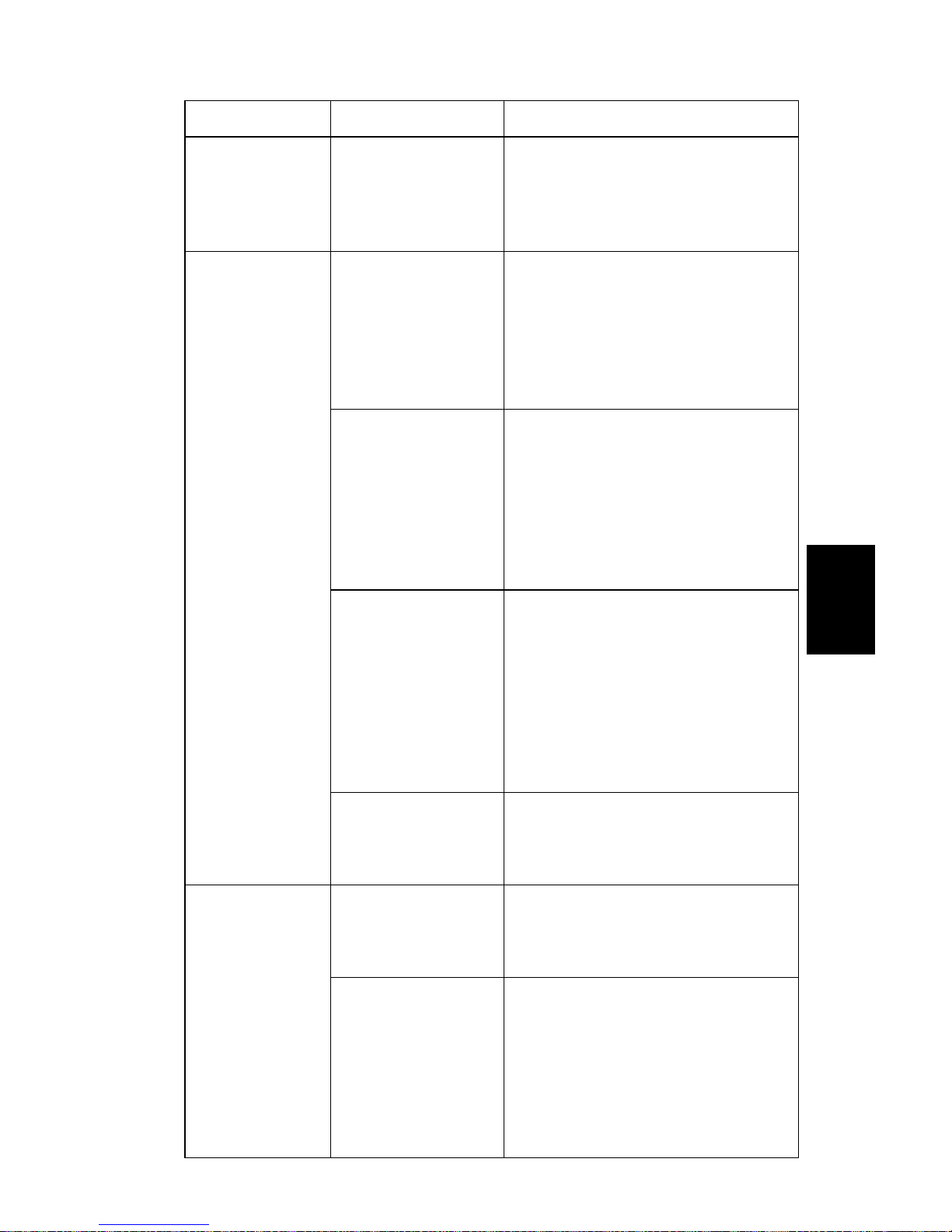
Table 4-1. Symptoms and Solutions
Problem Possible Cause Possible Solution
Yellow Enable
LED or green
Audio LED does
not illuminate
Fixture does n ot
respond to data
Color wheel or
gobo wheel is
not centered in
the beam or is
in the wrong
position
The volt age select
switch is not se ated
correctly.
Faulty XLR cable or
incorrect cable
linking.
There is no
controller attached
to the link, or the
controller is not
generating any
output.
Incorrect
personality settin g.
A fuse is blown.
Sensor or homing
slot is dirty.
Wheel is rubbing
against sensor.
Make sure the voltage select
switch is flush with the outer ring.
For more information, see
“Selecting the Voltage” on page
1-3.
a. Replace the XLR cables with
new or known working cables.
b. Veri fy that the XL R cabl es have
been correctly linked to the
fixture. For more information,
see “Linking the Fixtures” on
page 2-12.
Veri fy that the controll er is correctly
attached to the link (if applicable)
and that the controller is able to
generate output to a known
working fixture. For more
information, see “Specifications”
on page Intro-4 or “Linking the
Fixtures” on page 2-12.
a. Verify that the personality
switch settings you chose for
your control mode are correct.
b. Verify that the address switch
settings you chose f or the
fixture order or star ting channel
are correct. For more
information, see “Enabling the
Control Mode” on page 2-3.
Replace the F2 and/or F3 fuses on
the circuit board. For more
information, see “Replac ing Power
Supply Fuses” on page 3-4.
Clean the sensor a nd homing slot.
For more information, see
“Removing the Color Wheel or
Gobo Wheel” on page 3-10.
If the wheel is warped, contact
High End Systems customer
service (see “Getting Help” on
page Intro-3). If the wheel is not
warped, adjust the wheel
clearance. For more informat ion ,
see “Adjusting Wheel Clearance”
on page 3-12.
4
Trackspot User Manua l 4-3
Page 58

Table 4-1. Symptoms and Solutions
Problem Possible Cause Possible Solution
None of the
motors work
and the yellow
Enable LED
does not
illuminate
A fuse is blown.
Replace the F4 rear panel fuse
and the F1 circuit board fuse. For
more information, see “Replacing
Power Supply Fuses” on page 3-4.
4-4 Trackspot User Manual
Page 59

Appendix A
DMX Control of Trackspot
®
Under DMX 512 protocol, each Trackspot fixture uses a block of seven
contiguous DMX channels for a total of 72 fixtures per link. Although
you can control Trackspot from any DMX starting channe l you choose,
that starting channel must not interfere with another fixture’s channel
block.
The tables below assume that all Track spot fixtures will be assigned to
the same link, one after another . Keep in mind, however, that if you
mix different devices on the same link, those devices will have d ifferent
channel blocks that may overlap the 7-channel sequence listed below.
Note: The values displayed in the tables in this appendix may
vary slightly depending on your controller’s rounding
convention.
Start Channels and Construct P aram eters
If you chose DMX 512 protocol as your control mode, you must operate
your Trackspot fixture(s) either in low resolution or high resolution.
Control options available on your DMX controller will determine
whether you can operate your fixtures in low or high resolution mode.
Low Resolution Mode
Low resolution mode is used with DMX controllers that do not support
color or gobo fader and spin effects. There are fewer color and gobo
features available in low resolution mode.
High Resolution Mode
High resolution mode has more construct parameters and is intended
for DMX controllers with more accu rat e faders or direct numerical
control of each dim channel. In high resolution mode, the color fader
and gobo fader effects include half colors, oscillating colors, color sp in
effects, and gobo spin effects.
After determining which DMX 512 mode you will operate in, see Table
A-1 for information such as DMX starting channels and address and
personality switch settings in both high and low resolution modes. For
construct parameters available in low resolution mode, see Table A-2.
For construct parameters available in high resolution mode, see Table
A-3.
A
Trackspot User Manua l
Start Channels and Construct Parameters
A-1
Page 60

Table A-1. Starting channels in 7-channel DMX 512 protocol
Numerical
Order In
Link
Fixture 1 none 5 3, 5 001
Fixture 2 1, 2, 3 5 3, 5 008
Fixture 3 2, 3, 4 5 3, 5 015
Fixture 4 1, 3, 5 5 3, 5 022
Fixture 5 3, 4, 5 5 3, 5 029
Fixture 6 1, 2, 6 5 3, 5 036
Fixture 7 2, 4, 6 5 3, 5 043
Fixture 8 1, 5, 6 5 3, 5 050
Fixture 9 4, 5, 6 5 3, 5 057
Fixture 10 1, 2, 3, 4, 5, 6 5 3, 5 064
Fixture 11 2, 3, 7 5 3, 5 071
Fixture 12 1, 3, 4, 7 5 3, 5 078
Fixture 13 3, 5, 7 5 3, 5 085
Fixture 14 1, 2, 4, 5, 7 5 3, 5 092
Fixture 15 2, 6, 7 5 3, 5 099
Fixture 16 1, 4, 6, 7 5 3, 5 106
Fixture 17 5, 6, 7 5 3, 5 113
Fixture 18 1, 2, 3, 5, 6, 7 5 3, 5 120
Fixture 19 2, 3, 4, 5, 6, 7 5 3, 5 127
Fixture 20 1, 3, 8 5 3, 5 134
Fixture 21 3, 4, 8 5 3, 5 141
Fixture 22 1, 2, 5, 8 5 3, 5 148
Fixture 23 2, 4, 5, 8 5 3, 5 155
Fixture 24 1, 6, 8 5 3, 5 162
Fixture 25 4, 6, 8 5 3, 5 169
Fixture 26 1, 2, 3, 4, 6, 8 5 3, 5 176
Fixture 27 2, 3, 5, 6, 8 5 3, 5 183
Fixture 28 1, 3, 4, 5, 6, 8 5 3, 5 190
Fixture 29 3, 7, 8 5 3, 5 197
Fixture 30 1, 2, 4, 7, 8 5 3, 5 204
Fixture 31 2, 5, 7, 8 5 3, 5 211
Fixture 32 1, 4, 5, 7, 8 5 3, 5 218
Fixture 33 6, 7, 8 5 3, 5 225
Fixture 34 1, 2, 3, 6, 7, 8 5 3, 5 232
Fixture 35 2, 3, 4, 6, 7, 8 5 3, 5 239
Fixture 36 1, 3, 5, 6, 7, 8 5 3, 5 246*
Fixture 37 none 4 3, 4 257
Address
DIP Switches
ON
Personality DIP
Switches ON
Low High
Resolution Resolution
Starting
Channel
DMX
A-2
Start Channels and Construct Parameters
Trackspot User Manual
Page 61

Table A-1. Starting channels in 7-channel DMX 512 protocol
Numerical
Order In
Link
Fixture 38 1, 2, 3 4 3, 4 264
Fixture 39 2, 3, 4 4 3, 4 271
Fixture 40 1, 3, 5 4 3, 4 278
Fixture 41 3, 4, 5 4 3, 4 285
Fixture 42 1, 2, 6 4 3, 4 292
Fixture 43 2, 4, 6 4 3, 4 299
Fixture 44 1, 5, 6 4 3, 4 306
Fixture 45 4, 5, 6 4 3, 4 313
Fixture 46 1, 2, 3, 4, 5, 6 4 3, 4 320
Fixture 47 2, 3, 7 4 3, 4 327
Fixture 48 1, 3, 4, 7 4 3, 4 334
Fixture 49 3, 5, 7 4 3, 4 341
Fixture 50 1, 2, 4, 5, 7 4 3, 4 348
Fixture 51 2, 6, 7 4 3, 4 355
Fixture 52 1, 4, 6, 7 4 3, 4 362
Fixture 53 5, 6, 7 4 3, 4 369
Fixture 54 1, 2, 3, 5, 6, 7 4 3, 4 376
Fixture 55 2, 3, 4, 5, 6, 7 4 3, 4 383
Fixture 56 1, 3, 8 4 3, 4 390
Fixture 57 3, 4, 8 4 3, 4 397
Fixture 58 1, 2, 5, 8 4 3, 4 404
Fixture 59 2, 4, 5, 8 4 3, 4 411
Fixture 60 1, 6, 8 4 3, 4 418
Fixture 61 4, 6, 8 4 3, 4 425
Fixture 62 1, 2, 3, 4, 6, 8 4 3, 4 432
Fixture 63 2, 3, 5, 6, 8 4 3, 4 439
Fixture 64 1, 3, 4, 5, 6, 8 4 3, 4 446
Fixture 65 3, 7, 8 4 3, 4 453
Fixture 66 1, 2, 4, 7, 8 4 3, 4 460
Fixture 67 2, 5, 7, 8 4 3, 4 467
Fixture 68 1, 4, 5, 7, 8 4 3, 4 474
Fixture 69 6, 7, 8 4 3, 4 481
Fixture 70 1, 2, 3, 6, 7, 8 4 3, 4 488
Fixture 71 2, 3, 4, 6, 7, 8 4 3, 4 495
Fixture 72 1, 3, 5, 6, 7, 8 4 3, 4 502*
Address
DIP Switches
ON
Personality DIP
Switches ON
Low High
Resolution Resolution
Starting
Channel
DMX
A
*Note: Channels 253 - 256 and channels 509 - 512 cannot b e used
due to Trackspot’s 7-channel block structure.
Trackspot User Manua l
Start Channels and Construct Parameters
A-3
Page 62

Table A-2. Construct parameters in DMX 512 low resolution mode
DMX
Channel
1 Pan Pan Positioning, 8 bit 0-255 0-100 00-ffh
2 Tilt Tilt Positio nin g, 8 bit 0-255 0-100 00-ff h
3
4
Function
Color
Wheel
Gobo
Wheel
Low Resolution
Parameters
open / color 1
color 2
color 3
color 4
color 5
color 6
color 7
color 8
color 9
color 10
open / gobo 1
gobo 2
gobo 3
gobo 4
gobo 5
gobo 6
gobo 7
gobo 8
gobo 9
gobo 10
Decimal Percent Hex
0
32
54
79
110
138
160
200
210
240
0
32
54
79
110
138
160
200
210
240
0
13
21
31
43
55
63
78
82
94
0
13
21
31
43
55
63
78
82
94
0
20
36
4F
6E
8A
A0
C8
D2
F0
0
20
36
4F
6E
8A
A0
C8
D2
F0
closed
open
strobe 1
strobe 2
strobe 3
5 Shutter
6 Dimmer closed-open 0-255 0-100 00-ffh
7 MSpeed slowest-fastest 0-255 0-100 00-ffh
strobe 4
strobe 5
strobe 6
strobe 7
closed
open
0
26
51
77
102
128
153
179
204
230
242
0
10
20
30
40
50
60
70
80
90
95
0
1A
33
4D
66
80
99
B3
CC
E6
F2
A-4
Start Channels and Construct Parameters
Trackspot User Manual
Page 63
Table A-3. Construct parameters in DMX 512 high resolution mode
DMX
Channel
1 Pan Pan Positioning, 8 bit 0-255 0-100 00-ffh
2 Tilt Tilt Positioning, 8 bit 0-255 0-100 00-ffh
3
Function
Color
Wheel
High Resolution
Parameters
open / color 1
forward color spin 8
forward color spin 7
forward color spin 6
forward color spin 5
forward color spin 4
forward color spin 3
forward color spin 2
forward color spin 1
reverse color spin 8
reverse color spin 7
reverse color spin 6
reverse color spin 5
reverse color spin 4
reverse color spin 3
reverse color spin 2
reverse color spin 1
half color 2
color 2
half color 3
color 3
half color 4
color 4
half color 5
color 5
half color 6
color 6
half color 7
color 7
half color 8
color 8
half color 9
color 9
half color 10
color 10
half color 1
open / color 1
Decimal Percent Hex
0
8
15
22
30
36
43
51
59
64
71
79
87
94
99
107
112
120
128
133
140
148
156
163
168
176
184
191
196
204
212
219
224
232
240
247
252
0
3
6
9
12
14
17
20
23
25
28
31
34
37
39
42
44
47
50
52
55
58
61
64
66
69
72
75
77
80
83
86
88
91
94
97
99
0
8
F
16
1E
24
2B
33
3B
40
47
4F
57
5E
63
6B
70
78
80
85
8C
94
9C
A3
A8
B0
B8
BF
C4
CC
D4
DB
E0
E8
F0
F7
FC
A
Trackspot User Manua l
Start Channels and Construct Parameters
A-5
Page 64

Table A-3. Construct parameters in DMX 512 high resolution mode
DMX
Channel
4
Function
Gobo
Wheel
High Resolution
Parameters
open / gobo 1
forward gobo spin 7
forward gobo spin 6
forward gobo spin 5
forward gobo spin 4
forward gobo spin 3
forward gobo spin 2
forward gobo spin 1
reverse gobo spin 7
reverse gobo spin 6
reverse gobo spin 5
reverse gobo spin 4
reverse gobo spin 3
reverse gobo spin 2
reverse gobo spin 1
gobo 2
gobo 3
gobo 4
gobo 5
gobo 6
gobo 7
gobo 8
gobo 9
gobo 10
open / gobo 1
Decimal Percent Hex
0
10
18
28
38
46
56
64
82
92
99
110
117
128
135
155
179
191
201
209
217
227
235
245
252
0
4
7
11
15
18
22
25
32
36
39
43
46
50
53
61
70
75
79
82
85
89
92
96
99
0
A
12
1C
26
2E
38
40
52
5C
63
6E
75
80
87
9B
B3
BF
C9
D1
D9
E3
EB
F5
FC
closed
open
strobe 1
strobe 2
strobe 3
5 Shutter
6 Dimmer closed-open 0-255 0-100 00-ffh
7 MSpeed slowest-fastest 0-255 0-100 00-ffh
A-6
Start Channels and Construct Parameters
strobe 4
strobe 5
strobe 6
strobe 7
closed
open
0
26
51
77
102
128
153
179
204
230
242
0
10
20
30
40
50
60
70
80
90
95
Trackspot User Manual
0
1A
33
4D
66
80
99
B3
CC
E6
F2
Page 65

Appendix B
®
Trackspot
Use this appendix to determine the MSpeed (motor) movement times
in seconds. F ollow the listing in the tables below for the control mode
you chose to operate your fixture, either DMX 512 or LWR protocol.
DMX 512 Protocol MSpeed Times
The type of controller you use determines which Value column is
pertinent to your MSpeed Time. If you are using a controller that
shows MSpeed in numeric values, use the Value (num) column. If you
are using a controller that controls MSpeed with a fader, use the Value
(%) column.
Note: The values displayed in the Value columns may vary
slightly depending on your controller’s rounding
conventions.
Table B-1. DMX 512 protocol MSpeed times
MSpeed Times
Value
(%)
100 255 0.15 92 235 0.15
100 254 0.15 92 234 0.15
99 253 0.15 91 233 0.15
99 252 0.15 91 232 0.15
98 251 0.15 91 231 0.15
98 250 0.15 90 230 0.15
98 249 0.15 90 229 0.15
97 248 0.15 89 228 0.15
97 247 0.15 89 227 0.15
96 246 0.15 89 226 0.15
96 245 0.15 88 225 0.15
96 244 0.15 88 224 0.15
95 243 0.15 87 223 0.15
95 242 0.15 87 222 0.15
95 241 0.15 87 221 0.15
94 240 0.15 86 220 0.15
94 239 0.15 86 219 0.15
93 238 0.15 85 218 0.15
93 237 0.15 85 217 0.15
93 236 0.15 85 216 0.15
Value
(num)
Time
(seconds)
Value
(%)
Value
(num)
Time
(seconds)
B
Trackspot User Manua l
DMX 512 Protocol MSpeed Times
B-1
Page 66

Table B-1. DMX 512 protocol MSpeed times
Value
(%)
84 215 0.15 69 177 2.09
84 214 0.15 69 176 2.09
84 213 0.15 69 175 2.46
83 212 0.15 68 174 2.46
83 211 0.15 68 173 2.86
82 210 0.15 67 172 2.86
82 209 0.15 67 171 3.30
82 208 0.15 67 170 3.30
81 207 0.15 66 169 3.76
81 206 0.15 66 168 3.76
80 205 0.15 65 167 4.26
80 204 0.15 65 166 4.26
80 203 0.15 65 165 4.79
79 202 0.15 64 164 4.79
79 201 0.15 64 163 5.35
78 200 0.15 64 162 5.35
78 199 0.15 63 161 5.94
78 198 0.15 63 160 5.94
77 197 0.17 62 159 6.57
77 196 0.17 62 158 6.57
76 195 0.22 62 157 7.22
76 194 0.22 61 156 7.22
76 193 0.34 61 155 7.91
75 192 0.34 60 154 7.91
75 191 0.41 60 153 8.64
75 190 0.41 60 152 8.64
74 189 0.55 59 151 9.39
74 188 0.55 59 150 9.39
73 187 0.73 58 149 10.17
73 186 0.73 58 148 10.17
73 185 0.94 58 147 10.99
72 184 0.94 57 146 10.99
72 183 1.18 57 145 11.84
71 182 1.18 56 144 11.84
71 181 1.45 56 143 12.72
71 180 1.45 56 142 12.72
70 179 1.76 55 141 13.64
70 178 1.76 55 140 13.64
Value
(num)
Time
(seconds)
Value
(%)
Value
(num)
Time
(seconds)
B-2
DMX 512 Protocol MSpeed Times
Trackspot User Manual
Page 67
Table B-1. DMX 512 protocol MSpeed times
Value
(%)
55 139 14.58 40 101 38.65
54 138 14.58 39 100 38.65
54 137 15.56 39 99 40.23
53 136 15.56 38 98 40.23
53 135 16.57 38 97 41.85
53 134 16.57 38 96 41.85
52 133 17.61 37 95 43.50
52 132 17.61 37 94 43.50
51 131 18.69 36 93 45.19
51 130 18.69 36 92 45.19
51 129 19.79 36 91 46.90
50 128 19.79 35 90 46.90
50 127 20.93 35 89 48.65
49 126 20.93 35 88 48.65
49 125 22.10 34 87 50.43
49 124 22.10 34 86 50.43
48 123 23.30 33 85 52.24
48 122 23.30 33 84 52.24
47 121 24.54 33 83 54.09
47 120 24.54 32 82 54.09
47 119 25.80 32 81 55.96
46 118 25.80 31 80 55.96
46 117 27.10 31 79 57.87
45 116 27.10 31 78 57.87
45 115 28.44 30 77 59.81
45 114 28.44 30 76 59.81
44 113 29.80 29 75 61.78
44 112 29.80 29 74 61.78
44 111 31.19 29 73 63.78
43 110 31.19 28 72 63.78
43 109 32.62 28 71 65.82
42 108 32.62 27 70 65.82
42 107 34.08 27 69 67.89
42 106 34.08 27 68 67.89
41 105 35.57 26 67 69.99
41 104 35.57 26 66 69.99
40 103 37.09 25 65 72.12
40 102 37.09 25 64 72.12
Value
(num)
Time
(seconds)
Value
(%)
Value
(num)
Time
(seconds)
B
Trackspot User Manua l
DMX 512 Protocol MSpeed Times
B-3
Page 68

Table B-1. DMX 512 protocol MSpeed times
Value
(%)
25 63 74.28 12 31 113.28
24 62 74.28 12 30 113.28
24 61 76.48 11 29 115.98
24 60 76.48 11 28 115.98
23 59 78.71 11 27 118.73
23 58 78.71 10 26 118.73
22 57 80.97 10 25 121.50
22 56 80.97 9 24 121.50
22 55 83.26 9 23 124.31
21 54 83.26 9 22 124.31
21 53 85.59 8 21 127.14
20 52 85.59 8 20 127.14
20 51 87.95 7 19 130.01
20 50 87.95 7 18 130.01
19 49 90.33 7 17 132.91
19 48 90.33 6 16 132.91
18 47 92.76 6 15 135.85
18 46 92.76 5 14 135.85
18 45 95.21 5 13 138.82
17 44 95.21 5 12 138.82
17 43 97.69 4 11 141.81
16 42 97.69 4 10 141.81
16 41 100.21 4 9 144.84
16 40 100.21 3 8 144.84
15 39 102.76 3 7 147.90
15 38 102.76 2 6 147.90
15 37 105.34 2 5 151.00
14 36 105.34 2 4 151.00
14 35 107.95 1 3 154.13
13 34 107.95 1 2 154.13
13 33 110.60 0 1 157.28
13 32 110.60 0 0 157.28
Value
(num)
Time
(seconds)
Value
(%)
Value
(num)
Time
(seconds)
B-4
DMX 512 Protocol MSpeed Times
Trackspot User Manual
Page 69

LWR Protocol MSpeed Times
The table below lists MSpeed times in seconds for a numerical speed
range of 0 to 99.
Table B-2. LWR protocol MSpeed times
Speed # Time (seconds) Speed # Time (seconds)
0 157.28 34 67.89
1 154.13 35 65.82
2 151.00 36 63.78
3 147.90 37 61.78
4 144.84 38 59.81
5 141.81 39 57.87
6 138.82 40 55.96
7 135.85 41 54.09
8 132.91 42 52.20
9 130.01 43 50.43
10 127.14 44 48.65
11 124.31 45 46.90
12 121.50 46 45.19
13 118.73 47 43.50
14 115.98 48 41.85
15 113.28 49 40.23
16 110.60 50 38.65
17 107.95 51 37.09
18 105.34 52 35.57
19 102.76 53 34.08
20 100.21 54 32.62
21 97.69 55 31.19
22 95.21 56 29.80
23 92.76 57 28.44
24 90.33 58 27.10
25 87.95 59 25.80
26 85.59 60 24.54
27 83.26 61 23.30
28 80.97 62 22.10
29 78.71 63 20.93
30 76.48 64 19.79
31 74.28 65 18.69
32 72.12 66 17.61
33 69.99 67 16.57
B
Trackspot User Manua l
LWR Protocol MSpeed Times
B-5
Page 70

Table B-2. LWR protocol MSpeed times
Speed # Time (seconds) Speed # Time (seconds)
68 15.56 84 3.76
69 14.58 85 3.30
70 13.64 86 2.86
71 12.72 87 2.46
72 11.84 88 2.09
73 10.99 89 1.76
74 10.17 90 1.45
75 9.39 91 1.18
76 8.64 92 0.94
77 7.91 93 0.73
78 7.22 94 0.55
79 6.57 95 0.41
80 5.94 96 0.34
81 5.35 97 0.22
82 4.79 98 0.17
83 4.26 99 0.15
B-6
LWR Protocol MSpeed Times
Trackspot User Manual
Page 71

Appendix C
Personality and Address Switch
Settings
Personality Switch Settings
Table C-1. Personality switch settings for all control modes and
operating modes
Mode
Self Test 1
Set Up (Focus) 2
Lamp Save 1, 2
Auto Dim Override (LWR) 3, 4, 5
Pan Invert 6
Tilt Invert 7
Low Resolution DMX 512 mode (channels 1-256) 5
Low Resolution DMX-512 mode (channels 257-512) 4
High Resolution DMX 512 mode (channels 1-256) 3, 5
High Resolution D MX 51 2 mo de (c ha nne ls 257-5 12) 3, 4
LWR protocol and normal run All switches OFF
Standard Analog 4, 5
Stand Alone (Audio Master) 8
Stand Alone (Audio Slave) 3
Personality
Switches ON
Trackspot User Manua l
Personality Switch Settings
C
C-1
Page 72

Address Switch Settings
Address switch settings for LWR protocol and master/slave mode are
listed below. Address switch settings for DMX 512 protocol are listed
in Table A-1 on page A-2. When using standard analog control, set all
address switches OFF on all fixtures.
Table C-2. Address switch settings for LWR protocol and
master/slave mode
Fixture Number Address Switches ON
01
02 1
03 2
04 1, 2
05 3
06 1, 3
07 2, 3
08 1, 2, 3
09 4
10 1, 4
11 2, 4
12 1, 2, 4
13
14 1, 3, 4
15 2, 3, 4
16 1, 2, 3, 4
17 5,
18 1, 5
19 2, 5
20 1, 2, 5
21 3, 5
22 1, 3, 5
23 2, 3, 5
24 1, 2, 3, 5
All switches OFF (used
with LWR protocol only)
3, 4
C-2
Address Switch Settings
Trackspot User Manual
Page 73

Appendix D
Important Safety Information
English Version
WARNING: For Continue d Protection Against Fire
1. This equipment is designed for use with Philips type QT 8500, 250
watt lamp only. Use of any other type lamp may be hazardous and
may void the warranty.
2. Do not mount on a flammable surface.
3. Maintain minimum di stance of 1.0 meter (3.28 feet) from
combustible ma terials.
4. Replace fuses only with the specified type and rating.
5. Observe minimum distance to lighted objects of 1.0 meter (3. 28
feet).
WARNING: For Continued Protection Against Electric Shock
1. If this equipment was received without a line cord plug, attach the
appropriate line cord plug according to the following code:
• brown–live
•blue–neutral
• green/yellow–earth
2. As the colors of the cores in the mains lead of this equipment may
not correspond with the colored markings identi fying the terminals
in your plug, proceed as follows:
• the core which is colored green and yellow must be connected to the terminal in the plug which is marked with
the letter “E” or by the earth symbol , or colored green
or green and yellow.
• the core which is colored blue must be connected to the
terminal which is marked with the letter N or colored
black.
• the core which is colored brown must be conne cted to the
terminal which is marked with the letter L or colored red.
3. This equipment mu st be earthed.
4. Disconnect power before re-lamping or servicing.
5. Equipment suitable for dry locations only. Do not expose this
equipment to rain or moisture.
6. Refer servicing to qualified personnel; no user serviceable parts
inside.
7. Class I equipment - this fixture employs a grounded type
receptacle a nd is no t int end ed for co nn ectio n to a two w ire,
ungrounded sourc e of suppl y.
D
Trackspot User Manua l
Important Safety Information
D-1
Page 74

WARNING: For Continue d Protection Against Exposure To
Excessive Ultraviolet (UV ) Radiation
1. Do not operate this equipment without complete lamp enclosure in
place or if shields, lenses, or ultraviolet screens are damaged.
2. Change shields, lenses, or ultraviolet screens if they have become
visibly damaged to such an extent that their effectiveness is
impaired, for example by crack s or dee p scratches.
3. Never look directly at the lamp while lamp is on.
WARNING: For Continue d Protection Against Injury To Persons
1. Use secondary safety cable when mounting this fixture.
2. Equipment surfaces may reach temperatures up to 67° C (153° F).
Allow 5 minutes for cooling before handling.
3. Change the lamp if it becomes damaged or thermally deformed.
Appendice D
IMPORTANTES INFORMATIONS SUR
LA SÉCURITÉ
MISE EN GARDE: Pour Une Protection Permanente Contre Les
Incendies
1. Cet appareil est conçu pour être exclusivement utilisé avec des
lampes de 250 watts QT 8500. Son utilisation avec tout autre type
de lampe peut être dangereuse et annuler la garantie.
2. Ne pas monter les lampes sur une surface inflammable.
3. Maintenir à une dista n ce min imum de 1.0 mètre de matières
inflammables.
4. Ne remplacer les fusibles qu'avec des modèles et v aleurs as signées
recommandés.
5. Respecter une distance minimum de 1.0 mètre par rapport aux
objets éclairés.
MISE EN GARDE: Pour Une Protection Permanente Contre Les
Chocs Électriques
1. Si cet équipement est livré sans prise de cable, veuillez connecter
la prise de cable correcte selon le code suivant:
• marron - phase
•bleu - neutre
• vert/ j a une - terre
2. Débrancher le courant avant de changer les lampes ou d'effectuer
des réparations.
3. Cet équipement doit être uniquement utilisé dans des endroits
secs. Ne pas l'exposer à la pluie ou l'humidité.
4. À l'intérieur de l'équipement il n'y a pas de p ièces remplaçables p ar
l' utilisateur. Confiez l'entretien à un personnel qualifié.
D-2
Important Safety Information
Trackspot User Manual
Page 75

5. Equipement de Classe I - Cette piece fixe utilise une prise de
courant branché à la terre et elle ne doit pas être branché à une
source électrique, non reliée à la terre, à double fil.
MISE EN GARDE: Pour Une Protection Permanente Contre Des
Expositions Excessives Aux Rayons Ultra Violets (UV)
1. Ne pas utiliser cet appareil si le boîtier de la lampe n'est pas
complètement fixé ou si les blindages, lentilles, ou écrans
ultraviolets sont endommagés.
2. Changer les blindages ou les écrans ultraviolets s'ils sont
visiblement endommagés au point que leur efficacité aient été
altérée, par exemple par des fissures ou de profondes
égratignures.
3. Ne jamais regarder directement la lampe quand celle ci est
allumée.
MISE EN GARDE: Pour Une Protection Permanente Contre Les
Blessures Corporelles
1. Lors du montage, utiliser un câble de sécurité secondaire.
2. Les surfaces de l'appareil peuven t att eindre des températures de
67° C. Laisser refroidir pendant 5 minutes avant la manipulation.
3. Changer la lampe si elle est endommagée ou thermiquement
déformée.
Anhang D
WICHTIGE HINWEISE FÜR IHRE
SICHERHEIT
WARNUNG: Zum Schutz vor Brandgefahr
1. Dieses Gerät darf nur m i t 25 0 Watt Lampen vom Typ QT 8500 von
Philips verwendet werden. Der Gebrauch irgend eines anderen
Lampentyps könnte Sie gefährden und Ihre Garantie außer Kraft
setzen.
2. Das Gerät nie auf einer feuergefährlichen Fläche montieren.
3. Stets einen Mindestabstand von 1 Meter zu brennbaren
Materialien einhalten.
4. Zum Ersatz nur Sicherungen verwenden, die dem
vorgeschriebenen Typ und Nennwert entsprechen.
5. Einen Mindestabstand von 1 Meter zu den angestrahlten Objekten
einhalten.
WARNUNG: Zum Schutz Gegen Gefährliche Körperströme
1. Wenn dieses Gerät ohne einen Netzkabelstecker erhalten wurde,
ist der entsprechende Netzkabelstecker entsprechend dem
folgenden Code anzubringen:
• Braun - Unter Spannung stehend
D
Trackspot User Manua l
Important Safety Information
D-3
Page 76

•Blau - Neutral
• Grün/Gelb - Erde
2. Vor dem Austauschen von Lampen oder vor Wartungsarbeiten
stets den Netzstecker ziehen.
3. Diese Geräte sind nur zum Einbau in trockenen Lagen bestimmt
und müssen vor Regen und Feuchtigkeit geschützt werden.
4. Servicearbeiten sollten nur von Fachpersonal ausgeführt werden.
Das Gerät enthält keine wartungsbedürftigen Teile.
5. Dieses Gerät gehört zur Klasse 1 - Die s er Beleuchtungskörper
verwendet eine geerdete Fassung und sollte nicht an eine
zweipolige, ungeerdete Stromversorgung angeschlossen werden.
WARNUNG: Zum Schutz Gegen Übermässige Ultraviolett (UV)bestrahlung
1. Benutzen Sie dieses Gerät nur, wenn das komplette
Lampengehäuse fest eingebaut ist; ebenfalls dürfen keine der
Schutzabdeckungen, Linsen oder der UV-Schutz Beschädigungen
aufweisen.
2. Die Schutzabdeckungen, Linsen und der UV-Schutz müssen
ausgewechselt werden, wenn sie sichtlich dermaß en beschädigt
sind, daß sie ihre Wirksa mk eit einbüßen, z.B. infolge von Rissen
oder tiefen Krat zern.
3. Nie direkt in die eingeschaltete Lampe schauen.
WARNUNG: Zum Schutz Vor Verletzungen
1. Verwenden Sie bei der Installation des Beleuchtungskörpers ein
zusätzliches Sicherheitskabel.
2. Die Oberflächen des Gerätes können Temperaturen bis zu 67° C
erreichen. Vor dem Anfassen stets 5 Minuten lang abkühlen l assen.
3. Falls die Lampe beschädigt oder durch Wärmeeinwirkung
verformt ist, muß sie ausgewechselt werden.
Apéndice D
INFORMACIÓN IMPORTANTE DE
SEGURIDAD
ADVERTENCIA: Para Protección Continua Contra Incendios
1. Se ha diseñado este equipo para usarse con lámpara tipo Philips
QT 8500, 250 vatios. El uso de cualquier otro tipo de lámpara
puedá resultar peligroso, y puedá anular la garantía.
2. No monte el equipo sobre una superficie inflamable.
3. Mantenga una distancia mínima de material es com bustibles de 1,0
metro.
4. Cambie los fusibles únicamente por otros que sean del tipo y la
clasificación especificadas.
5. Guarda una distancia mínima a objetos iluminados de 1,0 metro.
D-4
Important Safety Information
Trackspot User Manual
Page 77

ADVERTENCIA: Para La Protección Continua Contra
Electrocuciones
1. Si se recibió e s te equipo sin el enchufe de alimen tacion, monte
usted el enchufe correcto según el clave siguente:
• moreno - vivo
• azul - neutral
• verde/amarillo - tierra
2. Desconecte el suministro de energía antes de recambiar lámparas
o prestar servicio de repara ción.
3. Este equipo se adecua a lugares secos sola mente. No lo exponga a
la lluvia o humedad.
4. Derive el servicio de reparación de este equipo al personal
calificado. El interior no contiene repuestos que puedan ser
reparados por el usuario.
5. Equipo de Clase 1. Este aparato emplea un enchufe hembra del
tipo unido a tierra, y no tie ne por fin alidad cone ctarse a una f uente
de alimentación bifilar y sin puesta a tierra.
ADVERTENCIA: Para Protección Continua Contra La Exposición A
Radiación Ultravioleta (UV) Excesiva
1. No opere este equipo sin tener colocada en su lugar la caja
protectora completa de la lámpara o bien, si el blindaje, los lentes o
las pantallas ultravioletas están dañadas.
2. Cambie el blindaje, los lentes o las pantallas ultravioleta si nota
una avería visible, a tal grado que su eficacia se vea comprometida.
Por ejemplo, en el caso de grietas o rayaduras profundas.
3. Jamás mire directamente a la lámpara en tanto ésta esté
encendida.
ADVERTENCIA: Para Protección Continua Contra Lesiones
Corporales
1. Use cable secundario de seguridad al montar este apa rat o.
2. Las superficies del equipo pueden alcanza r temperaturas má ximas
de 67 grados centígrados. Deje que se enfríen por 5 minutos antes
de tocarlas.
3. Cambie la lámpara si ésta se avería o deforma por acción térmica.
Appendice D
IMPORTANTI INFORMAZIONI PER LA
SICUREZZA
AVVERTENZA: Per La Prevenire Di Incendi
1. Questo apparecchio è stato disegnato per l'impiego esclusivo di
lampade tipo QT 8500, 250 Watt. L'uso di qualsiasi altro tipo di
lampada può essere pericoloso e può annullare la garanzia.
2. Da non montare sopra una superficie infiammabile.
3. Mant e n ere l' apparec c h io a un minimo di 1.0 me tri (3.28 pied i ) di
distanza dai materiali combustibili.
D
Trackspot User Manua l
Important Safety Information
D-5
Page 78

4. Rimpiazare i fusibili usando soltanto quelli del tipo e de lla taratura
adatta.
5. Mantenere una distanza minima di 1.0 metri (3.28 piedi) dagli
oggetti accesi.
AVVERTENZE: Per Prevenire Le Scosse Elettriche
1. Se questa apparecchiatura è stata consegnata senza una spina del
cavo di alimentazione, collegare la spina appropriata del cavo di
alimentazione in base ai seguenti codici:
• marrone - sotto tensione
•blu - neutro
• verde/giallo - terra
2. Questa apparecchiatura deve essere messa a terra
3. Disinnestare la corrente prima di cambiare la lampa dina o prima di
eseguire qualsiasi riparazione.
4. Questa apparecchiatura e' da usarsi in amb ienti secchi. Non e' da
essere esposta ne alla pioggia ne all' umidita'.
5. Per qualsiasi riparazione rivolgersi al personale specializzato. L'
utente non deve riparare nessuna parte dentro l' unita'.
6. Apparecchio di classe I - questo apparecchio è fornito di pre s a
bipolare + terra e non deve essere collegato a rete sprovvista di
terra.
AVVERTENZE: Per Proteggersi Contro Le Radiazioni Dei Raggi
Ultravioletti
1. Non usare questa apparecchiatura se il sistema di chiusura della
lampadina non e' completo o se gli scudetti, le lenti, o gli schermi
ultravioletti si sono visibilmente danneggiati di maniera tale che la
loro efficacia sia stata ridotta --- ad esempio , se vi sono visibili
spaccature o graffi profondi.
2. Mai guardare direttamente verso la lampad ina quando sia accesa.
AVVERTENZE: Per La Prevenzione Costante Di Danni Fisici Alle
Persone
1. Al montare questa apparechiatura, usare un secondo cavo di
sicurezza.
2. Le superfici della apparecchiatura possono arrivare a tempera ture
di 67 gradi centrigradi (153 gradi f). Aspettare 5 minuti prima di
maneggiare.
3. Cambiare la lampadina se si danneggia o se si e' deformata dovuto
alle alte temperature.
VIGTIG FIKKER HEDS INFORMATION DANMARK
Advarsel:
Vigtigt! Lederen med gul/groen isolation maa kun tilsluttes en
klemme maerket eller
D-6
Important Safety Information
Beskyttelse mod elektrisk chock.
Trackspot User Manual
Page 79

Glossary
Access door
The door that allows you to access the internal components of
Trackspot. See Figure 3-1 on page 3-2.
Channel blo ck
The contiguous block of DMX 512 channels a fixture uses to
control its constructs such as color wheel, gobo wheel, pan,
tilt, etc.
Color corrector
A means of matching a specific color temperature to simulate
standard types of light, such as Tungsten light or daylight.
Trackspot uses a dayl ight Color Temperature Blue (CTB) color
corrector.
Color tempe rature
A term used to describe the balance or content of each spectral
component of white light. Color temperature, in turn, relies on
the concept of the black body.
A black body is a theoretical object that absorbs all of the
energy that contacts it. Heating a black body causes it to emit
radiation. When the spectral composition of a black body
matches the spectral composition of a white light source, the
temperature of the black body (in degrees Kelvin) is the color
temperature of the light source.
For example, a light source that is rated at 320 0° Kelvin (such
as the light source used in Tracksp ot) matches the radiation of
a black body heated to 3200 ° Kelvin.
Because not all light sources exhibit a smooth spectral power
distribution, color temperature is an approximate measure of a
lamp’s spectral output.
Constructs
Features of the fi xtur e ( s uc h as c o l or w h ee l, gobo wheel and
shutter). A controller (such as the Intellabeam LCD Controller
for Trackspot) uses constructs to make it easy to program your
show.
Control mode
A method of sending data (either analog or digital) to a fixture.
There are four control modes available for Trackspot: DMX
512 protocol, LWR protocol, standard analog, or stand alone
operation.
Trackspot User Manual Glossary-1
Page 80

Dichroic
A dichroic (from Greek, meaning “two-color”) filter achieves a
richly-saturated color without using any pigmented (colored)
materials. In simple terms, it achieves this effect by either
reflecting or “cancelling out” through destructive interference
all but a narrow range of the light spectrum.
The “dichroic” name refe rs t o th e fact that one color (or broad
range of colors) is reflected or cance lled out, and one color (or
narrow range of colors) is transmitted through the dichroic
filter.
The dichroics used in Tracksp ot are all manuf actured at the
High End Systems Optical Coating and Assembly Laborator y
in Austin, Texas. They are made from a base of low expansion
glass material coated with multiple, microscopic layers of
specialized materials separated by junctions that either
transmit or reflect certa in wav ele ngths of light, accounting for
the resulting color.
Dichroic filters offer a number of advantages over traditional
gel filters: since they are made of low expansion glass and
absorb almost no heat themselves, they theoretically have no
failure mechanism; they transmit more light than gels; and
their resultant colors are m ore richly-sat urated than is possible
with a gel.
Dichroics are currently used for all T rack spot color and gobo
wheel dichroic filters.
(Dichroics are also used on other High
End Systems fixtures.)
DMX 512 control protocol
DMX 512 is a standard method of controlling lighting fixtures
and other devices (such as lasers and haze rs). Developed by
the United States Institute of Theatre Technology (USITT),
DMX 512 is supported by leading entertainment industry
equipment manufacturers, such as High End Systems.
DMX 512 (D for digital, MX for multiplex and 512 is the
number of channels per link) is a reliable, efficient and wellunderstood method of controlling lighting devices. Its strength
lies in its ability to control virtually any mix of DMXcompatible devices on the same link using a single DMXcompatible controller.
See also “LWR control protocol.”
DMX channel
The DMX 512 protocol allows a total of 512 channels to be
used on a particular link. You must assign a unique starting
channel to each Trackspot you wish to respond independently
Glossary-2 Trackspot User Manual
Page 81

to control commands. Multiple fixtures can be assigned the
same channel if you wish them all to respond to control
commands in the same way.
Fixture order
The control scheme used by LWR protocol, rather than a
starting channel which is used by DMX protocol.
Gobo
A metal disc with a shape or pattern cut out of the metal to
form a specific beam shape or pattern when used in Trackspot.
Some gobos contain dichroic glass. Custom gobos are
designed and manufactured at High End Systems. See
“Optional Accessories” on page Intro-6 for ordering
information.
Homing
The process of moving to a “home” or starting point that is set
by the fixture. In Trackspot, the pan and tilt motions of the
mirror, the shutter, and the color and gobo wheels all have a
designated home.
Hot Mirror
(Also called infrared filter or heat filter.) A piece of dichroic
glass placed over the opening of the reflector; see Figure 3-12
on page 3-10. Its purpose is to eliminate infrared and
ultraviolet wavelengths, both of which fall far outside the
visible light spectrum; therefore, light output is not affected. It
also helps prevent heat buildup inside the fixture.
LED (Light Emitting Diode) indicator
A light on the rear panel of the fixture that indicates activity of
the fixture’s cooling fan, enable (power input voltage), and
audio microphone.
Link
A group of fixtures joined by connecting data cables that
receive data from a controller or master fixture.
Luminaire
Another word for “fixture” or “lighting equipment.”
Lightwave Research (LWR) protocol
The native control protocol for Trackspot, LWR protocol offers
all the features of DMX 512 plus it gives you 10-bit resolution
for mirror positioning. Other control mode protocols only
allow for 8-bit resolution.
Trackspot User Manual Glossary-3
Page 82

MSpeed
A means of defining the time it takes for a motor to move to a
different defined position.
Operating mode
A setting that controls a fixture’s specialized function (such as
Auto Dim Override and Lamp Save) while the fixture is
configured for a control mode. There are two operating
modes, Self Test and Setup (Focus), w hich ov erride incoming
data from a c o n t r o l ler.
Optical sensor
A piece of equ ipm ent u sing an inf ra red be am tha t “s en ses” t he
homing slot on a wh eel to determin e the wheel’s home or
starti ng point.
Optimize
The process of positionin g a lamp inside its r eflector to achieve
the brightest possible light output with the brightest point of
light in the center of the beam. An optimized lamp prevents
the beam from damaging other internal components inside the
fixture.
QT 8500
A lamp specifically designed for use with Trackspot. This
lamp combines affordability, long lamp life (3 00 hour average),
reliability, high output, and stable color temperature
throughout the life of the lamp.
Starting c hannel
The first channel in a specific block of contiguous channels
used by a fixture in DMX 512 protocol. F or example, in a link
of Trackspot fixtures, the secon d fixtur e would use c hannel 8
as its starting channel due to Trackspot’s 7-channel block
structure.
Terminator
A terminator is a resistor inside an XLR connector. It is used to
prevent the di g i tal data from continuously “echoing” up a n d
down the data link. A terminator must be used on the last
fixture in every l in k, exc e pt for those fixtures con tr o lle d by
standard analog control. For instructions on constructing a
terminator, see “Constructing Terminators” on page 2-11.
Glossary-4 Trackspot User Manual
 Loading...