

HighEasy HY-8004HT, HY-8008HF, HY-8004HF, HY-8016HT, HY-8008HT User Manual
...
Embedded Hard Disk DVR
User’s Manual

Page 2 of total 94 pages
CONTENTS
CONTENTS.............................................................................................................................2
CHAPTER 1 INTRODUCTION ........................................................................................... 6
1.1 PRODUCT MODEL SUPPORTED................................................................................ 6
1.2 TECHNICAL INDEX.................................................................................................6
1.3 MAJOR FUNCTIONS ............................................................................................... 8
1.3.1 COMPRESSION FUNCTION..................................................................................8
1.3.2 VIDEO RECORDING AND STORAGE/BACKUP ...........................................................8
1.3.3 PREVIEW AND PLAYBACK......................................................................................8
1.3.4 A
LARM INTEGRATION FUNCTION...........................................................................9
1.3.5 P
AN/TILT CONTROL FUNCTION...............................................................................9
1.3.6 COMMUNICATION FIGURE ..................................................................................... 9
1.3.7 NETWORK OPERATION FUNCTION .......................................................................... 9
CHAPTER 2 INSTALLATION DESCRIPTION ...................................................................... 11
2.1 UNPACKING AND ACCESSORIES CHECK................................................................ 11
2.2 INSTALLATION ENVIRONMENT ............................................................................. 11
2.3 PRECAUTIONS FOR INSTALLATION ....................................................................... 11
2.4 HARD DISK INSTALLATION................................................................................... 12
2.5 PHYSICAL INTERFACE DESCRIPTION OF REAR PANEL .......................................12
CHAPTER 3 OPERATION INSTRUCTION.............................................................................15
3.1 K
EY DESCRIPTION OF FRONT PANEL .................................................................... 15
3.2 K
EY DESCRIPTION OF REMOTE CONTROLLER....................................................... 16
3.3 MOUSE OPERATION .............................................................................................17
CHAPTER 4 SYSTEM OPERATION................................................................................... 18
4.1 S
TARTUP AND SHUT DOWN .................................................................................. 18
4.1.1 STARTU P .............................................................................................................18
4.1.2 S
HUT DOWN ........................................................................................................19
4.2 RECORDING OPERATION ......................................................................................20
4.2.1 MANUAL RECORDING.......................................................................................... 20
4.2.2 TIMING RECORDING ............................................................................................20
4.2.3 EXTERNAL ALARM RECORDING ........................................................................... 20
4.2.4 MOTION DETECTION RECORDING ........................................................................20
4.3 ALARM DISTRIBUTION OPERATION ......................................................................21
4.4 PAN/TILT CONTROL OPERATION ...........................................................................21
4.5 NETWORK CONNECTION OPERATION ................................................................... 21
CHAPTER 5 SYSTEM MENU STRUCTURE........................................................................... 23
5.1 SYSTEM MENU STRUCTURE .................................................................................23

Page 3 of total 94 pages
5.2 BRIEF OF OPERATING MENU ................................................................................24
5.2.1 MENU ITEM SWITCHING AND SETTING ............................................................... 24
5.2.2 MENU ITEM LISTING............................................................................................25
5.3 MENU OPERATION ...............................................................................................28
5.3.1 RECORDING OPERATION ......................................................................................28
5.3.2 PLAYBACK OPERATION ........................................................................................28
5.3.3 PAN/TILT CONTROL .............................................................................................31
5.3.4 SYSTEM MENU .................................................................................................... 34
5.3.4.1 DESCKTOP MENU .............................................................................................. 34
5.3.4.2 VIDEO SEARCHING.............................................................................................. 38
5.3.4.3 SYSTEM INFORMATION ........................................................................................40
5.3.4.4 COMMON SETTING .............................................................................................42
5.3.4.4.1 G
ENERAL SETTING ..............................................................................................42
5.3.4.4.2 C
ODING SETTING................................................................................................. 44
5.3.4.4.3 TIMING SETTING.................................................................................................. 49
5.3.4.4.4 NETWORK SETTING ............................................................................................. 50
5.3.4.4.5 ALARM SETTING ................................................................................................. 53
5.3.4.4.6 MOTION DETECTION............................................................................................55
5.3.4.4.7 PAN/TILT SETTING ............................................................................................... 58
5.3.4.4.8 DISPLAY MODE....................................................................................................59
5.3.4.4.9 RESTORE DEFAULT .............................................................................................. 61
5.3.4.4.10 PROPERTIES OF ALARM OUTPUT .......................................................................... 61
5.3.4.5 ADVANCED ITEM ................................................................................................. 63
5.3.4.5.1 USER MANAGEMENT ...........................................................................................63
5.3.4.5.2 LOG INFORMATION ..............................................................................................66
5.3.4.5.3 CLEAR ALARM.....................................................................................................67
5.3.4.5.4 EXCEPTION HANDLING ........................................................................................67
5.3.4.5.5 R
ESTART SYSTEM ................................................................................................67
5.3.4.5.6 SYSTEM UPDATE.................................................................................................. 67
5.3.4.6 F
ILE MANAGEMENT.............................................................................................67
5.3.4.6.1 D
EVICE DETECTION............................................................................................. 67
5.3.4.6.2 B
ACKUP OPERATION ............................................................................................ 67
5.3.4.7 S
HUTDOWN SYSTEM............................................................................................ 67
CHAPTER 6
NETWORK OPERATION................................................................................ 67
6.1 INTRODUCTION FOR IE DISPLAY FIGURE ............................................................67
6.2 INTRODUCTION FOR CONFIGURATION FUNCTION .................................................67
6.2.1 SERVER PARAMETER SETTING .............................................................................67
6.2.2 CHANNEL PARAMETER CONFIGURATION.............................................................. 67
6.2.3 S
ERIAL PORT PARAMETER CONFIGURATION .........................................................67
6.2.4 A
LARM PARAMETER CONFIGURATION ................................................................. 67
6.2.5 USER MANAGEMENT SETTING .............................................................................67
6.2.6 DEVICE MANAGEMENT........................................................................................ 67
6.2.7 DEVICE STATE ..................................................................................................... 67
CHAPTER 7 SYSTEM UPDATE ........................................................................................67

Page 4 of total 94 pages
7.1 FTP UPDATE ........................................................................................................ 67
7.2 USB UPDATE.......................................................................................................67

Page 5 of total 94 pages
The user manual is applicable to HY-8004HT、HY-8008HT、HY-8016HT、
HY-8004HF、HY-8008HF、HY-8004HC、HY-8008HC、HY-8012HC、
HY-8016HC、HY-8012HS、HY-8016HS Hard Disk DVR.
The user manual may contain inaccurate information, or incompatible
with product function and operation, or misprint. The contents of this
manual will be updated along with the increasing of product function. We
will periodically modify and update products or procedure described in
the manual. The updated contents will be added in the new version of the
manual without prior notice.

Page 6 of total 94 pages
Chapter 1 Introduction
1.1 Product model supported
Compression format Product model Power consumption
HY-8004HF <30W
HY-8008HF <31W
HY-8004HT <16W
HY-8008HT <32W
D1 with audio
HY-8016HT <32W
HY-8004HC <15W
HY-8008HC <22W
HY-8012HC <30W
CIF with audio
HY-8016HC <37W
HY-8012HS <30W
CIF without audio
HY-8016HS <37W
1.2 Technical index
Operating system Embedded Linux
Video compression
standard
H.264
PAL: 176*144(QCIF)352*288(CIF) 704*576(D1) Resolution of coding
and decoding
NTSC: 160*120(QCIF)320*240(CIF) 640*480(D1)
Resolution of real time
monitoring image
PAL: 704*576(D1)
NTSC: 640*480(D1)
4-16-port (NTSC/PAL system automatic identification)
Video input
BNC (level: 1.0Vp-p, impedance: 75Ω)
VGA output
TV output: BNC figure 1.0Vp-p 75Ω
Video output
SPOT port output: BNC figure 1.0Vp-p 75Ω
Video frame rate PAL: 0-25F/S NTSC: 0-30F/S
Compression code rate
of video
16Kbps-4096Kbps can be determined according to product
Compression standard
of audio
G.726
Audio input 4-16-port BNC socket 2Vp-p impedance: 600Ω
Voice talking input 1-port phone plug RCA socket 2Vp-p 600Ω
Audio output 1-port phone plug RCA socket linear output 600Ω

Page 7 of total 94 pages
Hard disk Support 4 built-in IDE figures and 8 hard disks
Cabinet dimension
Length * width * height(mm)439 X 445 X 96(2U black
computer case)

Page 8 of total 94 pages
1.3 Major functions
1.3.1 Compression
Support 16- channel PAL/NTSC system video signal, use H.264 technology for video
compression, and support variable bit rate and variable frame rate
Support 16-channel audio signal with independent real-time compression for each channel of
audio signal, use G.726 technology for audio compression standard, and maintain steady
synchronization for sound and images
1.3.2 Video recording and storage/backup
Multiple record modes: manual recording, timing recording, alarm integration recording and
motion detection recording, in which motion detection and external alarm possesses
pre-recording and time delay functions
Multiplexing operation, which realizes independent and single real time record on each channel,
simultaneously realizes single-channel playback search, network monitoring and search files
search/download.
Maximum four built-in IDE figures, which may attach 1-8 hard disks with various capacities
Hard disk work management adopts non-working drivers sleep treatment, so as to reduce heat
emission and power consumption and prolong hard disk service life
Both coverage circulating record and non-circulating record are alternative for files on hard
disk
Provide hard disk backup for video information, and support storage and CD record (USB
burner, IDE burner) for USB devices (USB flash disk, portable hard disk)
1.3.3 Preview and playback
Support TV or VGA output connection
Display mode multiplexing (1/4/9/16) switch during the preview
Support OSD overlap and channel name overlap

Page 9 of total 94 pages
Support files playback modes, such as fast motion play item(2 times/4 times/8 times/16 times),
slow motion play item(1/2times, 1/4 times, 1/8 times, 1/16 times), single frame, previous file,
next file, etc.
Display accurate event time during the video playback
1.3.4 Alarm integration function
Have 8-channel external switch Alarm in, and video loss alarm, motion detection alarm
Support 4-channel alarm out
Relay alarm out, which is convenient for the realization of alarm integration and light control
on the spot
Alarm in and alarm out figure have protective circuit in order to prevent damage to the main
device due to this
1.3.5 Pan/Tilt/Zoom control function
Support Pan/Tilt/Zoom decoder via RS485 communication
Extensible multi-decoding protocol, which is convenient for the realization of Pan/Tilt/Zoom
and dome control function
1.3.6 Communication figure
Have RS485 figure, realize Pan/Tilt/Zoom control
Have RS232 figure, it can be used in connection to computer serial port so as to carry out
system maintenance and update, as well as matrix control
Have a standard Ethernet figure, realize network remote access function
Have USB figure, it is used in connecting USB mouse, keyboard, USB memory device
1.3.7 Network operation function
Can carry out remote real-time monitoring via network

Page 10 of total 94 pages
Remote end can carry out local recording and playback(playback quality has relations with
network situation)
Remote Capture image
Support TCP/IP protocol;, it can access directly via Windows IE browser

Page 11 of total 94 pages
Chapter 2 Installation description
2.1 Unpacking and accessories check
One host machine, one power cable, one remote controller, a
sheet of warranty card, one user manual book, one compact disk,
a pair of No.7 battery, four hard disk data line, one USB mouse
2.2 Installation environment
Far from high temperature heat resources and places
Avoid direct radiation of sunlight
Don’t put in damp places
Video recorder should be installed horizontal
Avoid installing in the places of strenuous vibration
Don’t put other devices on the video recorder
Video recorder should be installed in well ventilated places
Working temperature is 0℃~+55℃
Working humidity is 10%~90%
2.3 Precautions for installation
Confirm power input voltage match with device power voltage, and then turn on power switch
Pay attention to the case earth connection treatment of hard disk DVR
Confirm whether the hard disks are installed when it is installed for the first time
Recommend to use high speed hard disks with 7200 R/S and above
Page 12 of total 94 pages
2.4 Hard disk installation
Installing steps are as follows:
1) Open the computer case
2) If two hard disks are connected on a ATA hard disk data line, master and slave of hard disk
should be set up
3) Take down the fixed shelf for the hard disks
4) Put hard disk into the fixed shelf, and fix left and right sides of hard disk with screw
5) Install the fixed shelf back to the device, and fix it on the device with screw
6) Connect data line of ATA hard disk. data line has three joints, which can be connected with
the pin type socket of motherboard, master hard disk and slave hard disk pay attention to
aligning data line joints with pin numbers of pin type socket
7) Connect the power cable of hard disk
8) Cover the computer case and fix it with screw
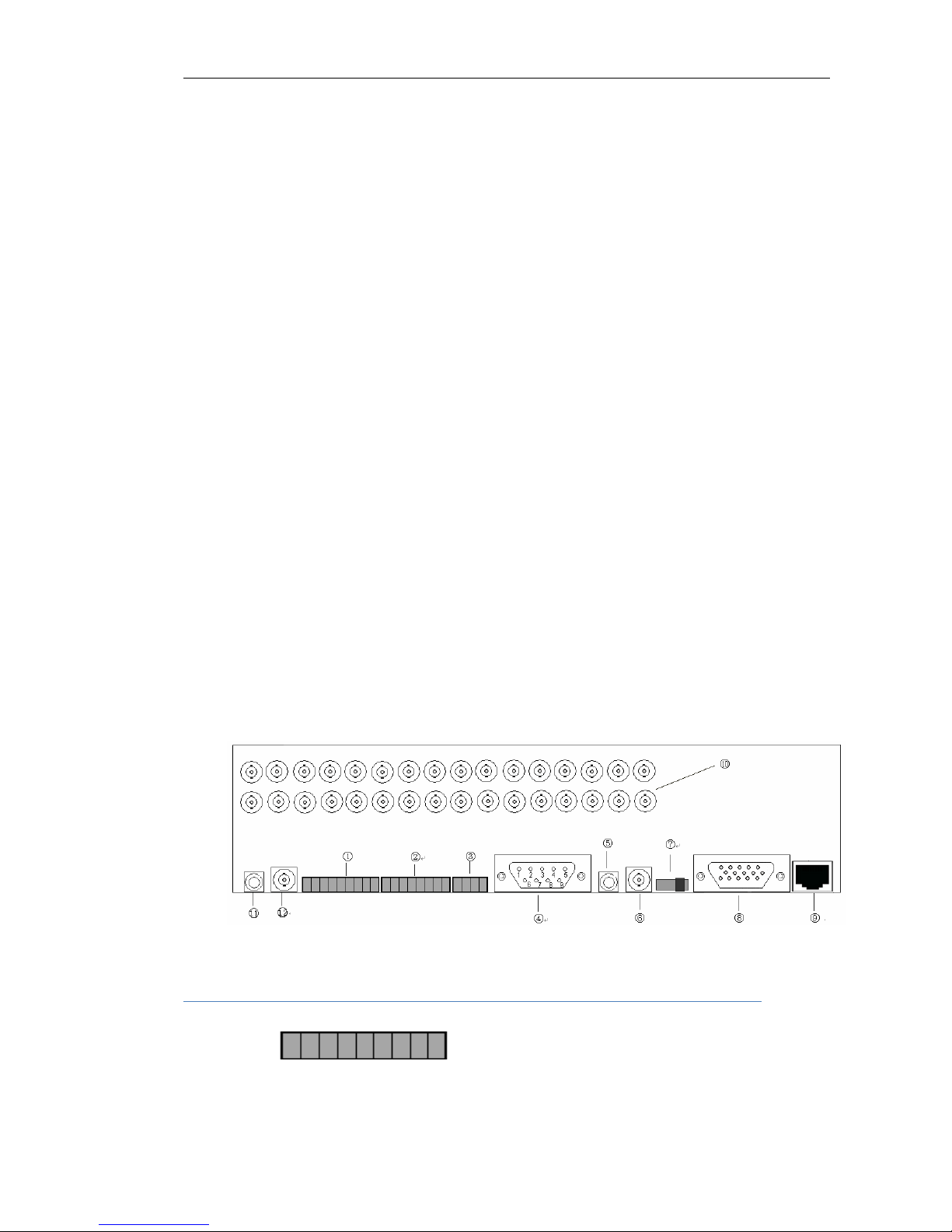
2.5 Physical interface description of rear panel
○1. 8-channel Alarm in:
Page 13 of total 94 pages
GND DIN8 … DIN1
8-channel normal open/normal close type switch quantity, share the same earth connection line
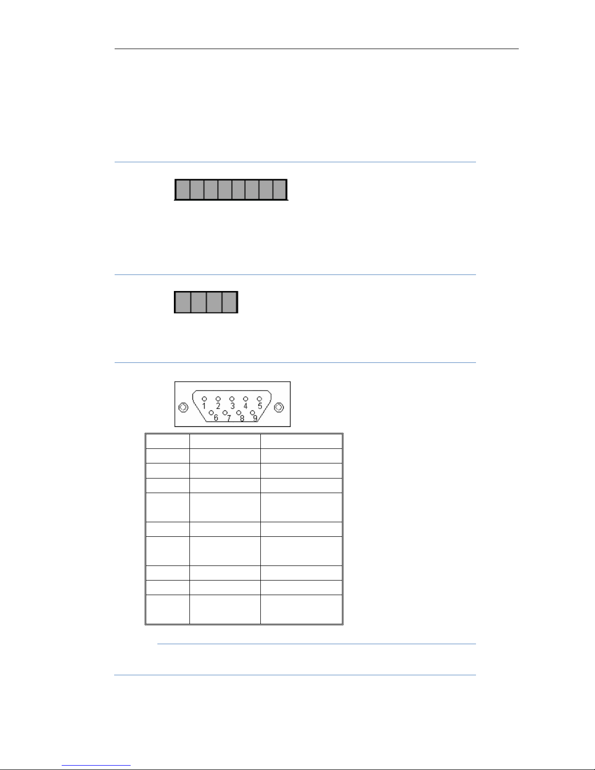
○2. 4-channel alarm out:
-4 +4 -3 +3 -2 +2 -1 +1
Normal open, relay closed output, 4-channel relay contact type switch quantity
○3. 485 output:
+12V GND 485B 485A
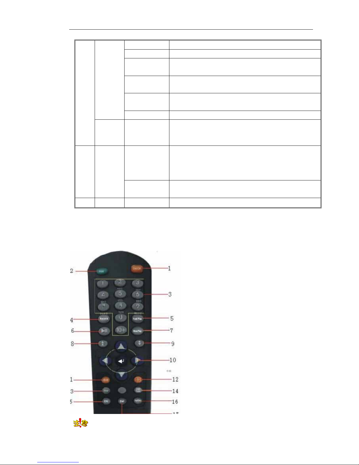
○4. RS232(DB9 pin), the definition is as follows:
○5. Audio output:
Connect with audio output device, such as horn and etc., which is used in voice talking and
Pin Name Description
1 DCD Carrier effective
2 TXD Transmit data
3 RXD Receive data
4 DTR
Prepare data
terminal
5 GND Signal ground
6 DSR
Prepare data
device
7 RTS Request to send
8 CTS Clear to send
9 RI
Trembling bell
signal

Page 14 of total 94 pages
audio preview and playback, RCA figure
○6. TV output:
1 TV output, BNC figure
○7. Side slide switch:
Select TV output or VGA output.
When switch slides to VGA side, output VGA signal;
When switch slides to TV side, output TV signal
TV
VGA
○8. VGA output:
Standard 15 core VGA figure
○9. Network figure:
1 10M/100M self-adapting Ethernet port (RJ45)
⑩. Audio and video input figure:
16 audio and video input figure, RCA figure
○
11
. Line input:
Voice talking input connector, RCA figure
○
12
. SPOT port:
Multiple selection(select one from sixteen), can select a corresponding channel video on SPOT
port output, output images should be original images without compression treatment. The first
channel output and BNC figure are the default item.

Page 15 of total 94 pages
Chapter 3 Operation instruction
3.1 Key description of front panel
① ② ③ ④ ⑤
No. Type Name Description
IR Remote control infrared figure
1 Figure
USB figure
Connect with USB storage device, USB mouse, USB burning
CD-ROM
Power Power indicator
Record Recording indicator
Alarm Alarm out indicator
Hard disk
Hard disk presents orange and flicking during read writing. If
indicator is off and no flicking, which means there is fault in
the hard disk of device
State Indicating key in main function state or sub-function state
2
State
lamp
Remote control Remote controller indicator
DEL
It is used to delete the current character when cursor is in
editing state
▲ Jump to the previous recording files during playback
▼ Jump to the next recording files during playback
Cn/En Chinese and English input method switch
PTZ PTZ control key
Play Play during playback, pause key;shortcut key for Fast Tips
Single frame Single frame operation shortcut key during playback
Record Manual recording shortcut key
Stop Stop shortcut key during playback
Exit Cancel current operation, back to last menu
3
Main
function
key
Multi window
1. Multi window switch during preview;2.switch between
Page 16 of total 94 pages
different window sizes during the playback
Auxiliary key Auxiliary function key
Canceling alarm
key
Cancel alarm
Slow motion
play
Select slow motion play key 1/2 times, 1/4 times, 1/8 times,
1/16 times during the playback
fast motion play
Select fast motion play key 2 times, 4 times, 8 times, 16 times
during playback
Switch key Switch between main function key and auxiliary key
Sub-
function
key
Number key
Can input numbers, uppercase and lowercase English letter
and Chinese character
Direction key
It consists of four keys, namely up【↑】, down【↓】, left【←】,
right【→】. 1. use【←】, 【→】key to move menu setup frame
when it is in menu mode, use【↑】, 【↓】keys to select menu
setup data;2.Pan/Tilt direction control and etc.
4
Control
key
Enter
1. confirmation operation of menu mode;2. switch between
selection frame
5 Switch POWER
Device switch
Note Key position of front panel for different model machine may have some differences, while the
definition of key function is similar.
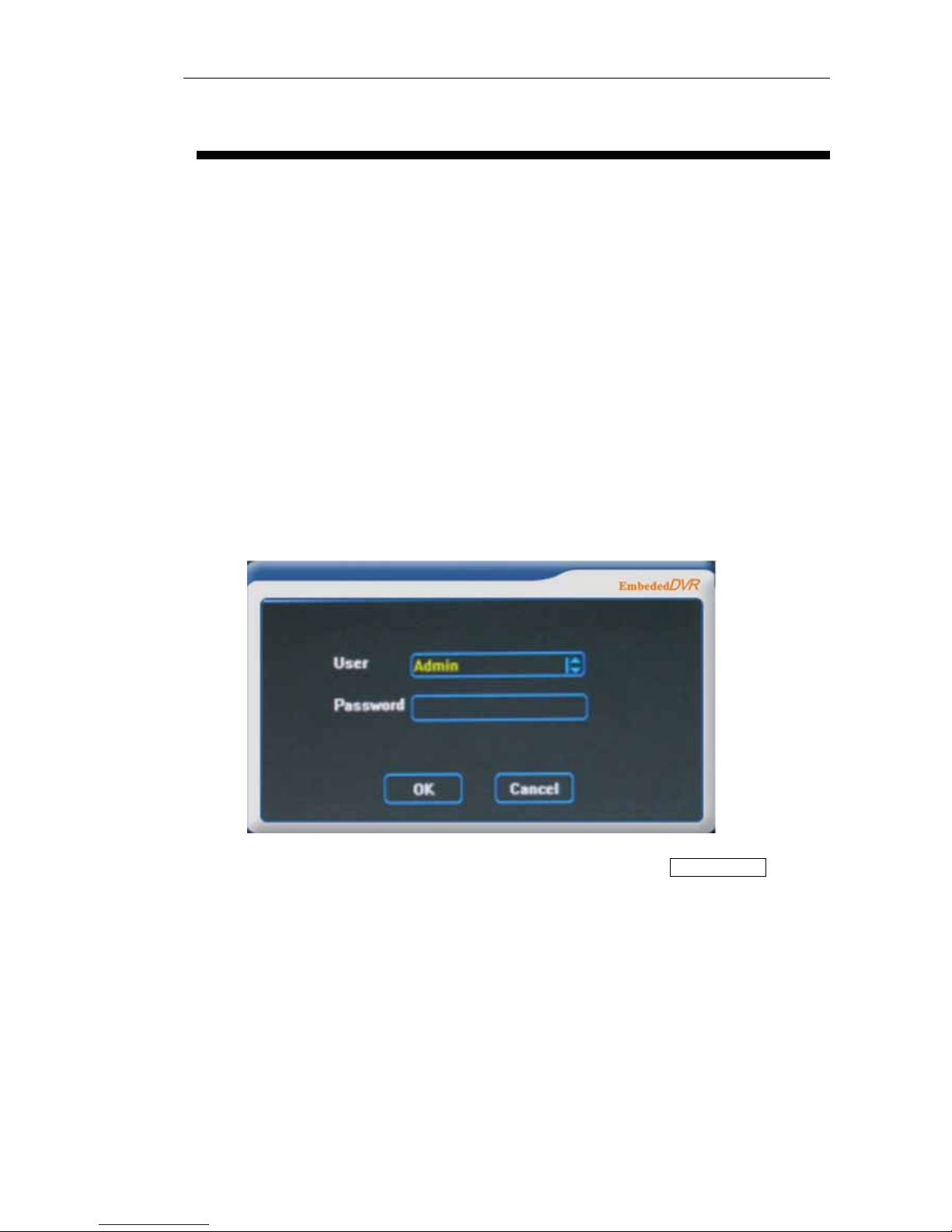
3.2 Key description of remote controller
Note Remote controller address should be same with the local number of normal setting;
No.
Name
d
escription of Name
1
On/off
turn on or turn off device
2
Address
Set corresponding remote
control address
3
Figure key
Same as the figure key of
front panel
4
CD Recording
Same as the manual
recording key of front panel
5
Fast play
Same as the fast play key of
front panel
6
Play
Same as the pause key of
front panel
7
Slow play
Same as the slow play key
of front panel
8
Last
paragraph
Same as the last paragraph
key of front panel
9
Next
paragraph
Same as the next paragraph
key of front panel
10
Confirm menu,
direction key
Same as the confirm,
direction key of front panel
11
Exit
Same as the exit key of front
panel
12
Multi-window
Same as the multi-screen
key of front panel
13
Stop
Same as the stop key of
front panel
14
Single frame
Same as the single frame
key of front panel
15
Chinese
Chinese and English switch
key
16
Auxiliary
Same as the auxiliary key of
front panel
17
Delete
Same as the delete key of
front panel

Page 17 of total 94 pages
otherwise, the remote control cannot control the device.
3.3 Mouse operation
Click mouse left key on a certain function menu icon and enter the content of the
menu
Carry out the operation indicated on the control
Change state of check box or motion detection module
Click figure box or pop up digital panel in password field, click directly on figure
on the panel, it can complete the figure input. × means clear or delete, √ means to
confirm the numerical value inputted, and close the panel
Click page up and down of rolling textbox, can select different item
Click the selected file (List Search)
Click left mouse
button
Click to cancel the set mosaic area
Double click to change the state of backup file Double click left
mouse button
Different windows display when switching playback by double clicked
During the preview monitoring, click right mouse button and pop up desktop menuClick right mouse
button
During playback, click right mouse button to hide or display play menu
Select motion detection area
Drag mouse
Drag slider of scroll bar or slider bar, complete the positioning when halt
Page 18 of total 94 pages
Chapter 4 System operation
4.1 Startup and shut down
4.1.1 Startup
Connect to the power cable, press the power switch on back panel, power indicator is on. When press
power key or switch key of remote controller, video recorder starts up. Video output default after startup
is multi window output mode, if startup time is within the setting time of timing recording, system will
start automatically timing recording function, recording indicator of corresponding channel will be on,
system works normally.
After normal startup, multi-window will pop up logon figure, as the following::
The default password is 888888, for the purpose of safety, users should change the the default
password in time, see Chapter 5 Menu operation for setup change→ advanced items.

Page 19 of total 94 pages
Input correct password, click OK key, login in successsingley, and then can carry out operation on
DVR.
4.1.2 Shut down
Method 1: press on/off key on panel for 3 seconds or more, and then can shut down the system;
Method 2: press directly on/off key on the remote control and then , can shut down the system;
Method 3: shut down the system from desktop menu main menu→ shut down system.

Page 20 of total 94 pages
4.2 Recording operation
Users can select different recording mode according to their demands, recording operation description
of different modes are as follows:
4.2.1 Manual recording
Two ways to operate manual recording
Method 1: press recording key of front panel or remote controller
Method 2: select manual recording on the desktop menu
When operate on manual recording,
means non-recording state, ■ means recording state,
mouse click can change its state, click save, it can start recording in accordance with the setting channel
state, and click cancel, it will cancel the setting;left and right direction on panel and remote
control can move the current channel to other channels, press ok key, it can change the channel state,
press ▼key, the focus can be moved to save button , press ok key, it can start recording according to the
set channel state, if you want to cancel the setting, press again, let the focus move to the cancel
button , and then press ok key, it can cancel the setting and exit.
4.2.2 Timing recording
Set the timing period of recording channel, see Chapter 5 main menu→ Common setting → timing
setting for details
4.2.3 External alarm recording
Alarm IN and OUT-figure of the back panel connects with alarm device, and set alarm settings, permit
Alarm in and alarm out, set external alarm recording time period, and then it can trigger recording
through the alarm integration, see Chapter 5 for detailed settings.
Main menu→ Common setting → alarm setting
4.2.4 Motion detection recording
First of all, confirm the motion detection recording channel is not in timing recording, if yes,
▲
▲
▲

Page 21 of total 94 pages
must cancel the timing recording
The time period of motion detection is required to set in timing setting. when implementing
motion detection setting, detecting area should be set
Motion detection may connect with alarm out, see Chapter 5 main menu→ Common setting
→ motion detection for detailed settings
4.3 Alarm distribution operation
Connect alarm devices for Alarm in, output figure on the back panel
Set recording time period of external alarm in main menu→ Common setting → timing
setting
Set alarm integration recording in main menu→ Common setting → alarm setting, see
Chapter 5 main menu→ Common setting → alarm setting for details
Set time period for alarm out in main menu→ Common setting → output attribute
4.4 Pan/Tilt/Zoom control operation
Confirm correct connection between Pan/Tilt/Zoom and decoder, and set the decoder address
Confirm correct connection between device and decoder
Carry out setting in Pan/Tilt/Zoom setting, see Chapter 5 main menu→ Common setting →
PTZ setting for details
In multi-window, on video channel required to carry out Pan/Tilt/Zoom control, click right
mouse button to enter Pan/Tilt/Zoom control, it can switch to the single window monitoring of this
video channel;To enter Pan/Tilt/Zoom control by remote control or panel will switch to the default
first channel, press on and down direction key can switch to other channels. To enter Pan/Tilt/Zoom
control in single window preview will enter this single window
Can use up key, down key, left key or right key to carry out corresponding moving and
controlling
4.5 Network connection operation

Page 22 of total 94 pages
Confirm computer host is connected correctly with DVR through net cable
Set IP address, subnet mask and gateway of DVR on main menu→ Common setting →
network setting
Check whether network is connected well with “ping” command
Open IE browser to access DVR
Connect DVR with client on computer host, see Chapter 6 for details

Page 23 of total 94 pages
Chapter 5 System menu structure
5.1 System menu structure
S
y
tem menu
coding setting
imer
Network
Alarm in
Motion detect
Pan setting
Display mode
estore default
Output attribute
Halt system
CommonlSettin
single window
4 Windows
9 Windows
16 windows
Pan Control
Video Color
Quick search
anual Recording
Lock Screen
Main Menu
Device Detect
Backup
Video Search
QuickSearch
List Search
Diisk information
ersionInformation
System information
Common setting
ser management
Log information
Clear alarm
Exception handling
Reboot system
Advanced setting
Update
ile management

Page 24 of total 94 pages
5.2 Description of operation menu
Mouse operation is simple, which has been introduced previously; the contents in this chapter are
mainly operation in remote control and panel
5.2.1 Menu item switch and setting
Enter main menu and submenu
a) After logining in successsingley, appear multi window preview mode, press ok key,
graphic user figure(later abbreviate it as GUI)figure like the right figure appeared:
b) Press direction key ▲▼, it can switch circularly system menu item to main menu, dark
yellow color one is the current selected menu entries(same as after)
c) Press ok key to enter main menu, see the following figure:
Page 25 of total 94 pages
d) Press direction key ▲ ▼, it can switch to select submenu
e) Press ok key to enter class one sub sub-menu
Enter class two sub-menu
Direction key ▲ ▼ can switch to select class one sub-menu
Press ok key to enter selected class two sub-menu
Set menu contents
a) Press direction key ▲ ▼, it can switch to selected setting class two sub-menu
item
b) Press direction key ▲ ▼ on rolling textbox, can fix selected class two sub-menu entries
c) Can press directly number key on figure and text input item to fix the item contents
d) Press direction key to select save, press ok key , to save the revision made just now
e) If you don’t want to save the revision or exit the setting figure, can press direction key to
select cancel, and then press ok key , or press directly exit key
NOTE It can make multiple channel menus setting before exit from the same level menu, and
then save uniformly.
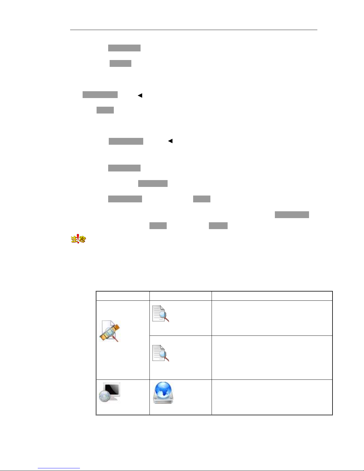
5.2.2 Menu item schedule
Main menu Sub-menu Item description
Quick Search
According to channel and time to locate the
playback files, when this time point doesn’t
match, it will playback the last recording files
before this time
Video search
List Search
According to recording type(common, manual,
alarm, motion detection), channel and time to
carry out list search the result will display in list
form, and make playback after selecting of files
in list
System information
Disk information
Display IDE figure state, type, total capacity,
avail capacity and state of each hard disk
▲
▲
▲
▲
Page 26 of total 94 pages
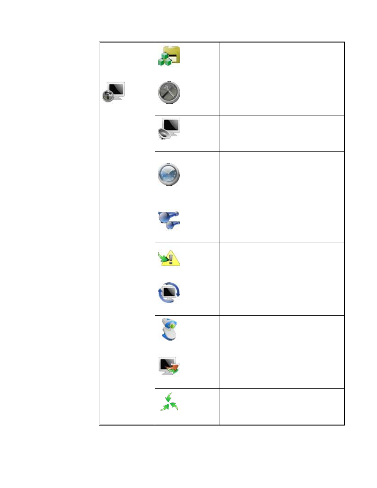
Version information
Display information, such as number of
channels, Alarm in and output port quantities,
hardware version, software version, issuing date
and serial number and etc.
Common setting
Basic parameter setting, system time, date,
video storage parameter, serial number, signal
mode, window saver, language selection and
self-start when power supply is on
encoding setting
Set encode format, recording code rate, frame
rate, bit control method, video lost alarm, OSD,
dual-stream and mosaic, and so on
Timing
Set time period of four recording types,
including timing recording, alarm out, motion
detection and motion detection | alarm out, two
time period can be set for each type every day,
which include also all setting used in all
channels
Network setting
Set DVR IP address, subnet mask, gateway, http
port, media port, CMD port, management
server, PPPoE, dynamic domain name and NAT
etc.
Alarm setting
Real time Alarm in, device type, linkage
recording channel, linkage alarm out and handle
with Alarm in time section
Motion detecting
Set sensitivity of motion detection, detection
area and corresponding treatment
Pan setting
Set Pan/Tilt/Zoom decoder address and
parameters of Pan/Tilt/Zoom device
communication protocol, baud rate, data bit,
stop bit, verify and serial type and etc.
Display mode
Set parameters displayed on menu, such as
transparency, monitor patrol and loop output and
etc.
System settings
Restore Default
Resume default Common setting s
Page 27 of total 94 pages
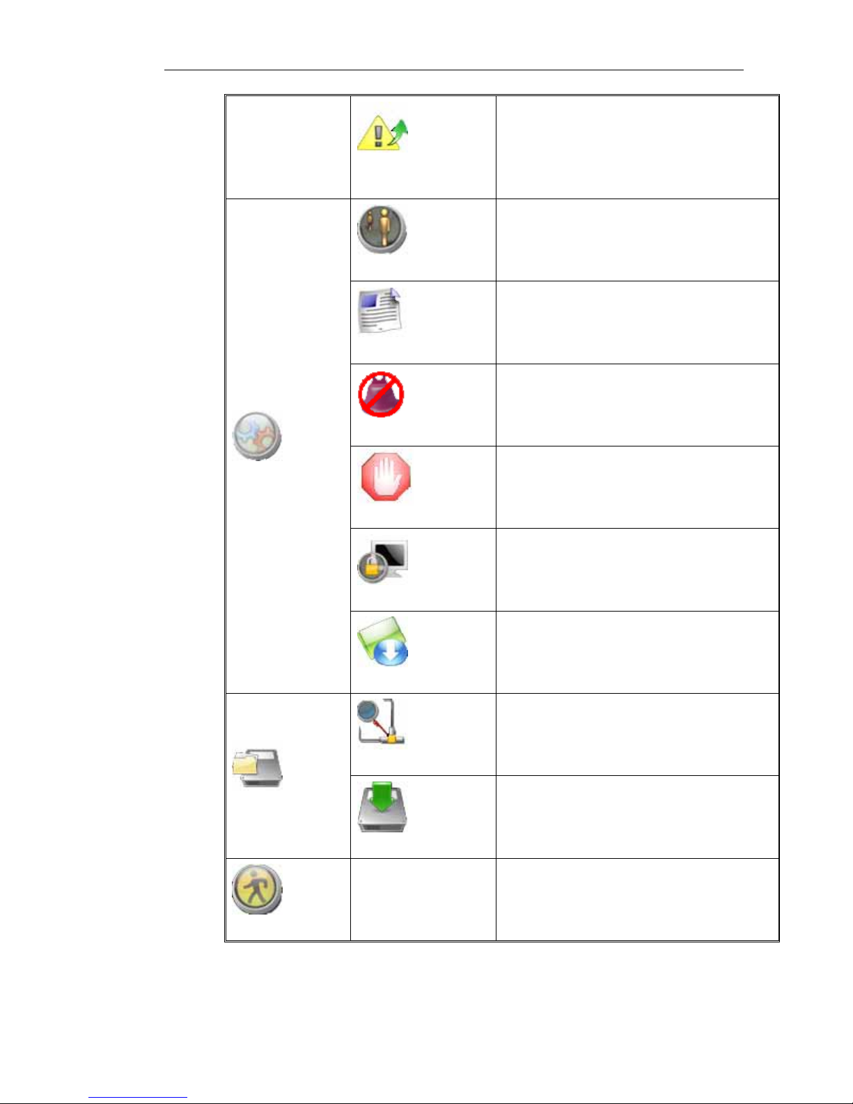
Property of alarm
output
Set time period for alarm output and delay time
when alarm output ends
User management
Add and delete new user, modify user’s
password, set local operation right and remote
operation right and etc.
Log information
Search system logs according to different query
conditions
Clear alarm
Manually clear alarm, including motion
detection, Alarm in, video loss linkage alarm
treatment
Exception handling
Handle system exception such as hard disk
single, IP collision, hard disk error, illegal
access, net broken and etc.
Reboot system
Restart the system
Advanced Settings
System Update
Update system packages by FTP or USB
Device detecting
Detect backup device, and list detected device
type, name, total capacity and space available
and so on
Backup File
Backup operation
Select target files and backup to external storage
device
Halt System
Shut down the DVR
Page 28 of total 94 pages
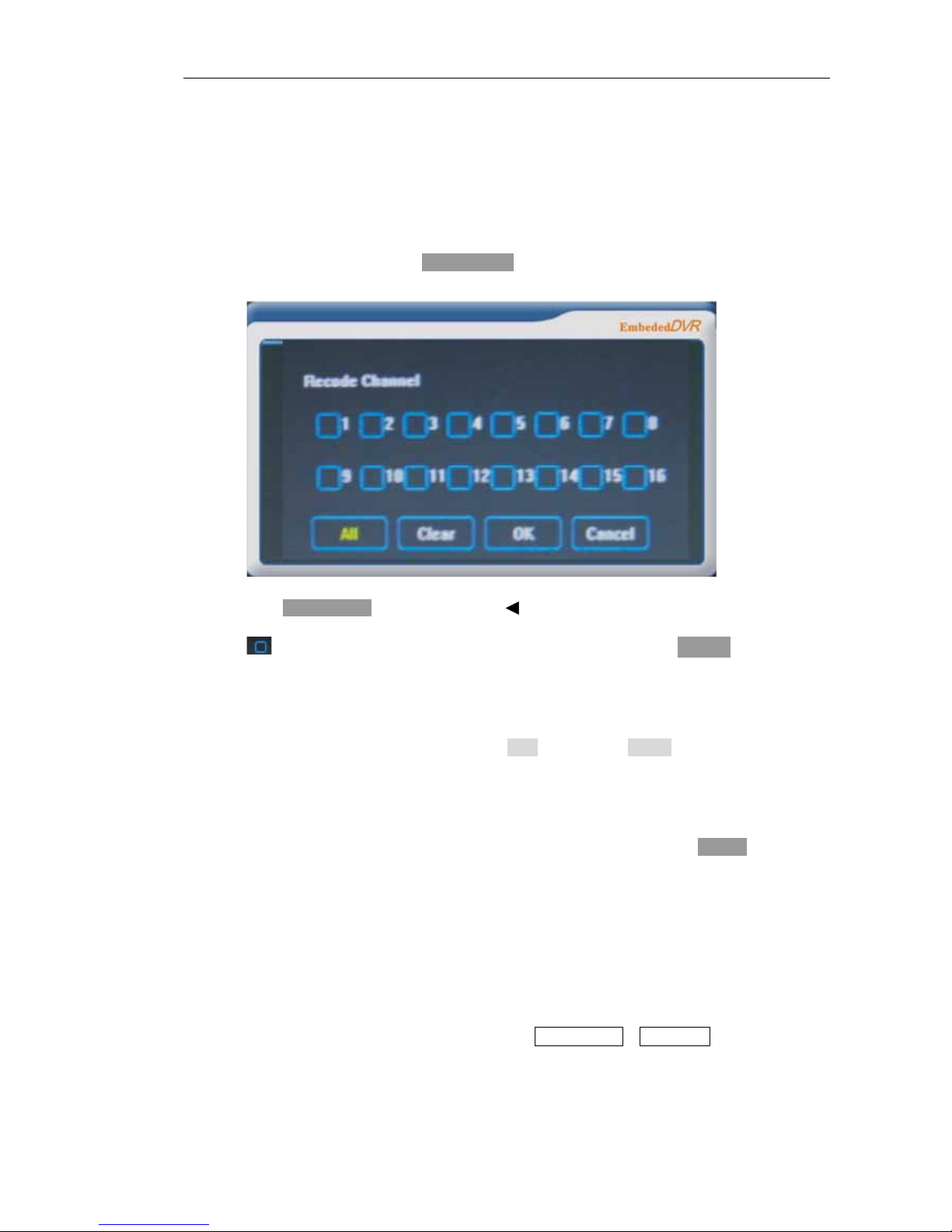
5.3 Menu operation
5.3.1 Recording operation
a) On preview window, press recording key , pop up the following recording control dialogue
figu
a)
b) Press direction key to switch to recording channel
c) means non- recording state, ■ means recording state, press ok key to change the
recording channel state;
d) Press ▼ to select all, press ok key can enable all recording channels to be in recording state;
press left and right direction key to select clear button, press ok key will change the selected
recording state into non-recording state;Press left and right direction key to select confirm,
press ok key will make the DVR to run according to setting state.
e) If you want to cancel the setting, press again, select cancel, press ok key and then can
cancel the setting and exit.
NOTE Also It can operate manual recording from desktop system menu.
5.3.2 Playback operation
It can enter the following playback dialogue figure from Quick Search or List Search:
▲
▲
▲
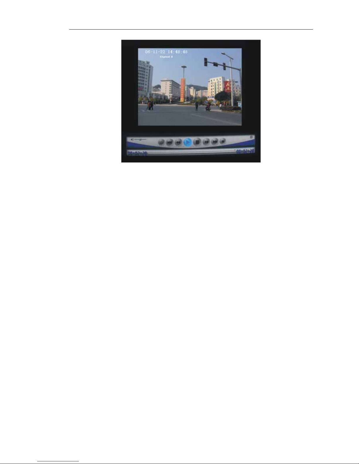
Page 29 of total 94 pages
 Loading...