

Hifonics ZXi200.2, ZXi150.4, ZXi40.4, ZXi60.4+1K, ZXi80.4 User Manual

ZXi200.2
ZXi40.4 / ZXi80.4 / ZXi150.4
ZXi60.4+1K
General Installation Procedure..........................................................................................................................................................................................1
Amplifier Feature Descriptions...........................................................................................................................................................................................2
ZXi200.2 2-CHANNEL AMPLIFIER APPLICATIONS.......................................................................................................................................................3
Full range stereo / mono
ZXi40.4 / ZXi80.4 / ZXi150.4 4-CHANNEL AMPLIFIER APPLICATIONS.......................................................................................................................4-5
4, 3 and 2 channel operation / front/rear high pass using a 2 channel model for mono sub bass
ZXi60.4+1K 5-CHANNEL AMPLIFIER APPLICATIONS..................................................................................................................................................6
5 channel discrete operation / single stereo RCA input with 5 channel output
Features and Specifications.............................................................................................................................................................................................. 7
Setting Up SystemsAfterInstallationForBestPerformance..............................................................................................................................................8
TroubleshootingandDiagnostics.......................................................................................................................................................................................9
Product Warranty.............................................................................................................................................................................................................10
The contents of this manual may not be reproduced or copied with out the written consent of MAXXSONICS USA, Inc.
Z
EUS HIGH PERFORMANCE AMPLIFIERS
The Zeus ZXi Series products have been designed to a very high level of performance, with features unavailable in
a
ny other product. All of the amplifiers have variable crossovers built in, with added touches such as subsonic
f
ilter, bass equalization and a remote Level control module(some models) that allows subwoofer Level control from
t
he drivers seat.
To ensure years of listening pleasure, all amplifiers have a built in diagnostic mode that will detect shorted speaker
l
eads, low impedance, dangerous high temperatures, DC shorts and will shut down the amp to prevent serious
d
amage.
Check out our videos of new products,
events and technical tutorials at
www.youtube.com/maxxsonicsusainc
GENERAL INSTALLATION PROCEDURE
1
System Design
Installation
The success of any car stereo system relies on several factors, such as the system design, execution of the installation, and system setup. Please
r
emember that any system is only as good as its weakest link.
Please remember that higher power systems are not necessarily useful purely for high sound pressure levels, but also to establish a headroom capability, to
r
eproduce musical peaks cleanly without distortion. Lower power amplifiers will clip earlier than their more powerful cousins, and cause loudspeaker failure when
o
verdriven, due to the harmonics generated by a clipped signal, thus overheating voice coils.
Amplifiers should be mounted with the fins running horizontally for best convection cooling, to minimize overheating. Purchase the best quality RCA cables you can
a
fford, for reliability and less engine noise interference in the audio system.
General:
Run the wiring so that RCA cables are at least 18“ away from power and speaker cables. Keep RCA cables away from electrical devices in the vehicle that can cause
e
lectrical noise, such as electric fuel pumps, emission control modules and other on-board electronic modules.
Power and ground connections(see the features matrix on page 7 for proper gauge cables per amplifier):
Use a sufficient gauge power cable and ground cable using the chart below as reference to what size wire you require. Zeus series amplifiers require at least 4 gauge
p
ower wire. In a multi amplifier system, add the total value of the manufacture recommended fusing to get your total system amperage. Some applications may
r
equire multiple runs of power wire to meet the system requirements. In multi amplifier systems it is advisable to mount a large enough fuse right at the battery, and
r
un one or multiple +12 volt power cables to a fused distribution block near the amplifiers. It is then a simple matter to connect the +12 volt terminal of each amplifier
t
o the distribution block. During this process, please ensure that the main power fuse is removed to avoid shorting the electrical system. The main fuse must be within
1
2” of the vehicles battery.
Ground each amplifier with as short a ground lead as possible directly to the vehicle chassis using at least 4 gauge wire or equivalent to the size of the amplifiers’
power wire. Use a ground distribution block, if you wish, but it is extremely important to keep the main ground lead from this distribution block to the chassis as short
a
s possible , not more than 12“. The ground connection integrity to the chassis is very important, and the best way to achieve a good, solid electrical and mechanical
c
ontact is to use a large round crimp lug, crimped and soldered to the ground cable. The next step is to scrape the paint off the vehicle chassis , slightly larger than
t
he ground lug, at the connection point. Drill a clearance hole in the chassis, the same size as the lug hole, and use a bolt, spring washer and nut to securely fasten
t
he ground lug. Use petroleum jelly to coat the bolt/lug connection, to prevent oxidization with time.
TIP: Use the same approach when installing head units, equalizers or any audio equipment for that matter - run short individual grounds from each piece directly to
t
he vehicle chassis, to minimize ground loops and system noise. All power, ground and speaker connections should be crimped and soldered for reliability. Make sure
t
hat none of the cable insulation can chafe against exposed metal in the vehicle, causing short circuits to the chassis.
Safe connection sequence:
After all cables are run, connect speaker wires to the speakers and amplifiers, then run and plug in RCA cables. Next, connect all power, ground, and remote turn on
l
eads. Now connect all +12 volt cables to the amplifier/s and distribution blocks and fuse holders. Finally, connect the main +12 volt cable to the battery, with the main
f
use removed, and we are almost ready to power up the system.
Power up the system:
The following procedure may seem like overkill, but there is nothing more frustrating when turning on a system for the first time, and it does not work properly
i
mmediately.
First, make sure the head unit is off, and turn all level controls to minimum (counterclockwise), including the head unit volume control. Set all equalizers to 0 dB (no
b
oost), and all crossover frequency controls at approximate frequencies, as recommended by the loudspeaker manufacturer. Set all input selector and crossover
s
witches as required for the application. Remove all amplifier fuses, and insert the main fuse at the battery. If the fuse does not blow, you can insert the fuse in one of
t
he amplifiers, and we are ready to turn on the system. Turn the head unit on, insert a CD, or select a radio station, and increase the head unit volume control. If the
s
ystem sounds fine, turn off the head unit, and install fuses in the remaining amplifiers, one by one, till the complete system is powered up and functioning properly.
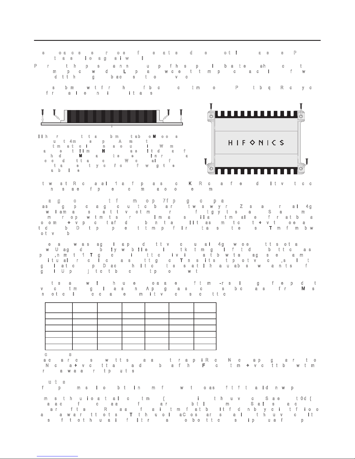
It is highly recommended that the amplifier be mounted to a board of MDF or other solid
s
tructure using the 4 mounting screws provided. Avoid mounting the
a
mplifier to metal as this can introduce noise and other unwanted issues. When mounting
t
he amplifier, ensure that it is mounted HORIZONTALLY, as shown in the diagram above, for
o
ptimal heat dissipation. Mounting amplifiers to speaker enclosures is not recommended as
t
his can cause damage to the amplifier components. When choosing a location for
m
ounting the amplifier, ensure that you check for clearance from wires, gas tank, electrical
d
evices and brake lines etc.
NOTE: This Matrix is a general rule
of thumb. Please refer to the
manufacturers specific
requirements. ZXi specifications
can be found on page 7.
WOOD
7-10 ft. 10-13 ft. 13-16 ft.
16-19 ft. 19-22 ft. 22-28 ft.
SYSTEM
AMPERAGE
35-50
50-65
68-85
85-105
105-125
125-150
8
6
4
4
4
2
6
4
4
2
2
0
4
4
2
2
0
0
4
4
2
2
0
0
4
4
2
2
0
0
4
2
0
0
0
0
WIRE LENGTH
WIRE GAUGE
H F
AMPLIFIER FEATURE DESCRIPTIONS
ZEUS ZXi AMPLIFIERS:
C
AUTION: DO NOT OPERATE ANY AMPLIFIER BELOW THE INTENDED IMPEDANCE. YOU
E
ach model is capable of 4 & 2-Ohms stereo per channel, or 4-Ohms mono bridged operation
!
!
WILL CAUSE DAMAGE TO THE AMPLIFIER THAT WILL NOT BE COVERED UNDER THE
e
xcept the 5 channel which is capable of 1-Ohm on channel 5.
WARRANTY PRINTED IN THE BACK OF THE MANUAL. 2 & 4 Channel amps are capable of 4
!
The input sensitivities for rated output powers are variable from 0.2 volts to 6 volts.
! All crossovers are fully variable in their respective ranges.
and 2-Ohms wired stereo and 4-Ohms wired mono bridged. The 5 channel amp is capable of 4,
!
Crossover filters are 12dB/Octave.
2 and 1-Ohm operation on the 5th channel ONLY.
! APOWER LED indicates the powered up and turned on condition.
! All Hifonics amplifiers feature a comprehensive diagnostic system, with speaker lead short circuit,
a
nd amplifier DC faults indicated by the red “PROTECT” LED.
2
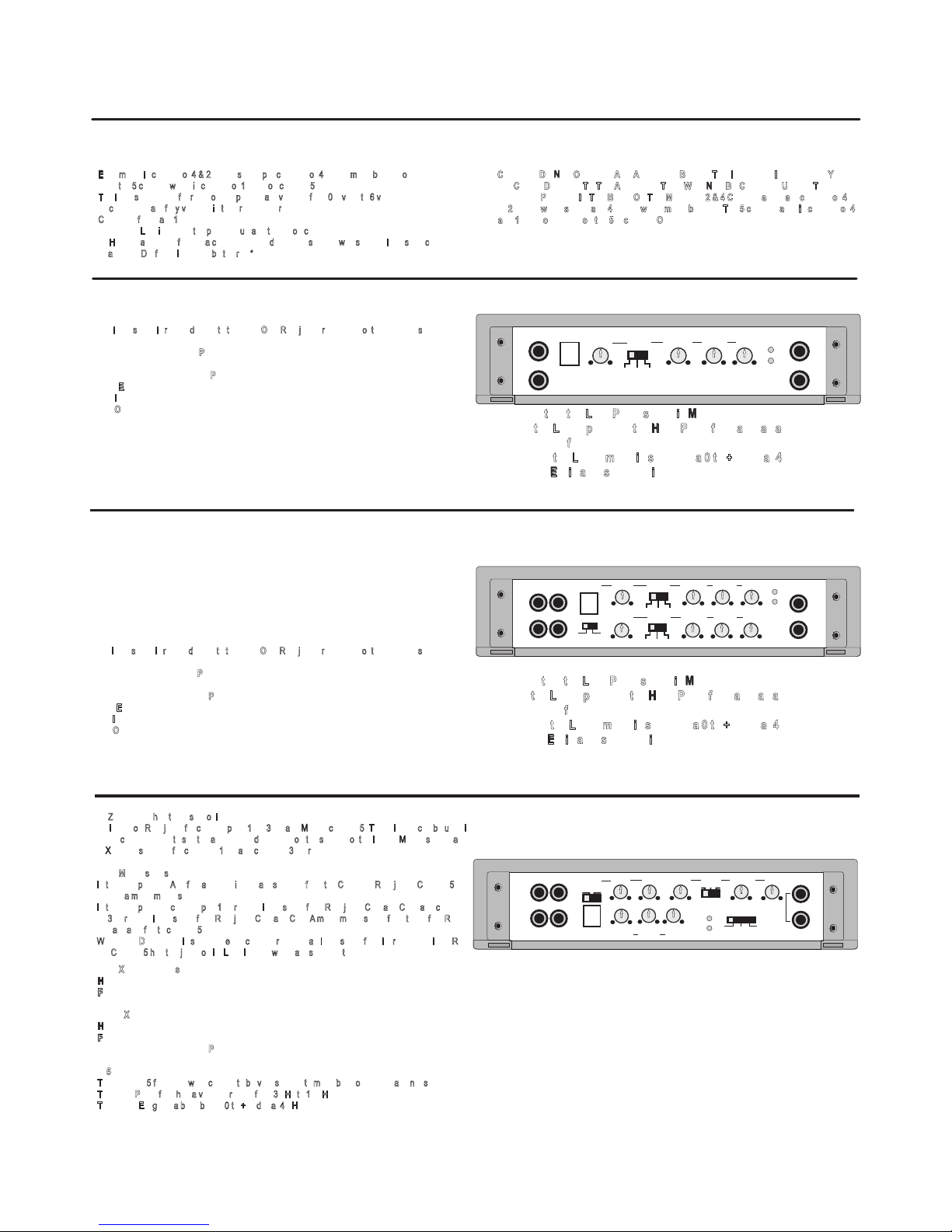
ZXi60.4+1K 5-CHANNEL AMPLIFIERS
The 4channel amps have thesame features asthe2 channel modelsaccept that there are2 sets of
controls.
1 setfor channels1 & 2and 1set for channels3 &4.
In addition, the4 channel models have aModeswitch. Switch to 2 channelifyou only have 1 setof
RCA’sin CH 1/2 andthe unit willautomaticallysupply signal to channels3/4. Select 4channelif you
are providingRCA’stochannels 1/2and 3/4.
The X-OVERslide switchselects the internalcrossover functions:
-The input signal is routed directly to the LINE OUT RCA jacks, regardless of the X-OVER setting
s
implifying daisychaining ofamplifiers.
-HP: Selectsthe builtin HIGH PASS filter,variable from10 Hz to15kHz.
-FULL: Bypassesall crossoversfor full frequencyrange operation.
-LP/BP: Selectsthe builtin LOW PASS ,variable from 30Hz to150Hz.
LINE INPUT:The lineinput accepts unbalanced(RCA) inputsfrom0.2V to6V.
LINE OUTPUT:The line output passesthrough signal fromtheline inputs which allowsyou to daisy
chain multipleamplifiers fromone signal.
BASS EQ: Fixed 45Hzbass boostvariablefrom 0dBto 10dB.
Note that the LOW PASS signal is MONO.
-In the LP/BP position, the HIGH PASS filter acts as a
s
ubsonic filter.
-When the LP/BP mode is selected, a 0 to +10dB, at 45Hz,
B
ASS EQ is also switched in.
ZXi40.4 / ZXi80.4 / ZXi150.4 4-CHANNEL AMPLIFIERS
The X-OVERslide switchselects the internalcrossover functions:
-The input signal is routed directly to the LINE OUT RCA jacks, regardless of the X-OVER setting
s
implifying daisychaining ofamplifiers.
-HP: Selectsthe builtin HIGH PASS filter,variable from10Hz to 15kHz.
-FULL: Bypassesall crossoversfor full frequencyrange operation.
-LP/BP: Selectsthe builtin LOW PASS ,variable from 30Hzto 150Hz.
BASS EQ: Fixed 45Hzbass boostvariablefrom 0dBto 10dB.
LINE INPUT:The lineinput accepts unbalanced(RCA) inputsfrom0.2V to6V.
LINE OUTPUT:The line outputpasses through signalfrom the lineinputs which allowsyouto daisy
chain multipleamplifiers fromone signal.
Note that the LOW PASS signal is MONO.
-In the LP/BP position, the HIGH PASS filter acts as a
s
ubsonic filter.
-When the LP/BP mode is selected, a 0 to +10dB, at 45Hz,
B
ASS EQ is also switched in.
ZXi200.2 2-CHANNEL AMPLIFIERS
HP FULL LP/BP
10Hz 15KHz
30Hz 150Hz
0dB 10dB
6V 0.2V
REMOTE
HI PASS LOW PASS
BASS EQ
LEVEL POWERX-OVER
PROTECT
LINE INPUT
L
R
L
R
LINE OUT
LINE INPUT
REMOTE
POWER
PROTECT
LINE OUT
HI FULL LP/BP
HI FULL LP/BP
6V 0.2V
10Hz-15KHz
30Hz-150Hz
0dB-10dB
HI PASS LOW PASS
BASS EQ
LEVEL
X-OVER
1/2 CH
6V 0.2V
10Hz-15KHz
30Hz-150Hz
0dB-10dB
X-OVER
3/4 CH
HI PASS LOW PASS
BASS EQ
LEVEL
MODE
CH2-CH4
L
R
L
R
L
R
CH1/2 CH3/4
The ZXi60.4+1K has three sets of inputs:
Line inputs on RCA jacks for channel pairs 1&2, 3&4, and MONO channel 5. These inputs can be used in
v
arious combinations, to suit the application, depending on the settings of the INPUT MODE switch, and
t
he X-OVER switches for channels 1&2, and channels 3&4, respectively.
INPUT MODE slide switch:
- In the CH2 position, ALL five amplifier inputs are selected from the CH1/CH2 RCA jacks. Channel 5
r
eceives a mono mixed signal.
- In the 4CH position, channel pair 1&2 receive input signal from RCA jacks CH1 and CH2, and channel
p
air 3&4 receive input signal from RCA jacks CH3 and CH4. A mono mixed signal from these four RCA
jacks are also fed to channel 5.
- When 5CH DISCRETE is selected, each channel receives an input signal from its respective input RCA
jack. Channel 5 has two jacks on its LINE INPUT, which are summed together.
CH1/2 X-OVER slide switch:
- HI: Selects the HIGH PASS filter, variable from 10Hz to 15KHz.
- FULL: Sets this pair to full range operation.
CH3/4 X-O VER sl ide switc h:
- HI: Select s the HIGH PASS fi lter, v ariable from 10H z to 1 5KHz.
- FULL: Sets this pair to full range operation.
-LP/BP: Selectsthe builtin LOW PASS ,variable from 30Hz to150Hz.
CH 5:
- The channel 5 functions were chosen to be very specific to mono bass operation, and not switchable:
- The LOW PASS filter has a variable range from 30 Hz to 150 Hz.
- The BASS EQ gives a bass boost, 0 to +10 dB, at 45 Hz.
REMOTE
POWER
PROTECT
LINE INPUT
CH1
CH2
CH3
CH4
5CH
10Hz 15Khz
10Hz 15Khz
HI PASS
6V 0.2V
LEVEL
6V 0.2V
LEVEL
LOW PASS
30Hz 150Hz
HI PASS
MODE
Ch2 Ch4 Ch5
X-OVER
CH3/4
0dB-10dB
30Hz 150Hz
6V 0.2V
BASS EQ
LOW PASS
LEVEL
HI FULL
HI FULL BP
X-OVER
CH1/2
POWER INPUT
GND REM BATT+12V
SPEAKER OUTPUT
RIGHT LEFT
- + - +
BRIDGED
FUSE
HP FULL LP/BP
10Hz 15KHz
30Hz 150Hz
0dB 10dB
6V 0.2V
REMOTE
HI PASS LOW PASS
BASS EQ
LEVEL POWERX-OVER
PROTECT
LINE INPUT
L
R
L
R
LINE OUT
POWER INPUT
GND REM BATT+12V
SPEAKER OUTPUT
RIGHT LEFT
- + - +
BRIDGED
FUSE
HP FULL LP/BP
10Hz 15KHz
30Hz 150Hz
0dB 10dB
6V 0.2V
REMOTE
HI PASS LOW PASS
BASS EQ
LEVEL POWERX-OVER
PROTECT
LINE INPUT
L
R
L
R
LINE OUT
3
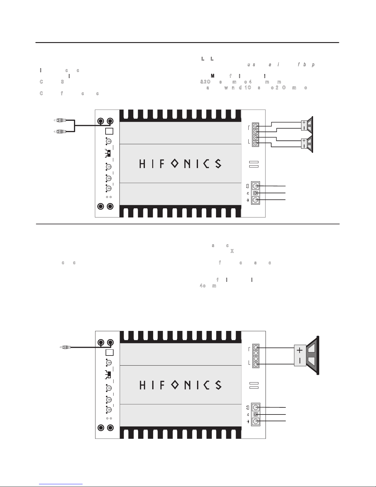
ZXi200.2 2-CHANNEL AMPLIFIER APPLICATIONS
4. Line Level:
This is themostbasicapplication for theHFiSeries2 channel amplifiers.
Refer to thesection“Setting up systems after installation for best performance”
1. Interconnect cable checklist:
Connect the LINE INPUTS tothe Radio/CD withgood qualityRCAcables.
NOTE: Minimum final loudspeaker impedances:
2. Crossover Switch:
4 & 2 Ohms stereo mode or 4-Ohms mono mode
The X-OVER switchmustbein the FULL position.
This amplifier will not do 1 Ohm stereo or 2/1 Ohm mono operation.
3. Crossover frequency control checklist:
N/Aforfull range operation.
FULL RANGE STEREO
MONO
S
witch setting checklist:
This application illustrates the basic mono bridging method for all Hifonics
- TheAMPLIFIER X-OVER switchshould beintheLP/BP position.
amplifiers.
Crossover frequency control setting checklist:
Interconnect cable checklist:
LPF: 11o’clock
A MONO signal source is required, such as would be available from the mono
sub bassoutputofanactivecrossover, whether stand alone,or built intoahead
Minimum final loudspeaker impedance:
unit or equalizer. Important: Do not be tempted to connect the hot, or positive
outputs, from any source together to obtain a mono signal, as this could very
- 4 ohm mono.
well damage theoutputstageof that source.
It is necessary to feed the SAME signal to both left and right inputs via a Yadapter RCAcable. Connect themonospeakerpositive terminal to theLEFT+,
and its negativeterminaltoRIGHT -.
FULL RANGE
STEREO LINE INPUT
REMOTE TURN-ON
REMOTE TURN-ON
CHASSIS GROUND
CHASSIS GROUND
TO BATTERY +12v
VIA FUSE
TO BATTERY +12v
VIA FUSE
FULL RANGE
SPEAKERS
FULL RANGE
MONO LINE INPUT
VIA Y-ADAPTER
FROM MONO SOURCE
MONO SPEAKER
or SUBWOOFER
 Loading...