

Hifonics TW10D4, TW12D4, TW12D2, TW10D2, TW15D4 Quick Start Installation Manual
...
Sealed enclosures offer a range of performance
proles depending on the internal air volume.
Larger enclosures will have a smoother more
extended response while a small enclosure
will have increased output in a more focused
frequency range. Sealed enclosures are the
simplest to construct but do require that the box
be completely air tight.
Vented designs offer the ability to tune the
enclosure. Larger enclosures will have a
smoother more extended response while a
small enclosure will have increased output
in a more focused frequency range. Vented
enclosures are more difcult to construct but
offer more overall output.
• Use 3/4” MDF
• Make sure the woofer mounting panel is
full width and height
• Glue all mating surfaces
• Use wood screws
• Use silicone caulk on all internal joints
The internal volume of the
enclosure must be determined
to insure proper performance.
Simply measure height, width and
depth of enclosure you intend
to build. Subtract the material
thickness. Multiply these numbers
and divide by 1728 to get the
volume in cubic feet.
For enclosures with an angled
panel, measure the larger and
smaller depths, add these
together and divide by two. Use
this averaged depth.
Enclosure
Volume
D
H x W x D
1728
D1 + D2
2
Sealed
Vented
Enclosure types
Volume calculation
Subwoofer dimensions
CAUTION
Always consider consulting a professional audio installer
before installing new subwoofers. High power audio
systems have the ability create sound levels above 130dB.
Extended exposure to high sound pressure levels can
cause hearing damage.
Always run any new wiring through safe areas that wont
interfere with the normal operation of the vehicle.
Congratulations on your choice of a Hifonics subwoofer.
This “Quick Start Installation” guide is meant to help you
“hook up” and play music. For more detailed information
on system setting, speaker and subwoofer conguration,
and full specications by model, visit the website at
Hifonics.com
It’s a good idea to conrm that you have purchased the
correct size subwoofers to t your vehicle. If you have any
reservations about being able to complete the installation
yourself, we recommend contacting a professional. Be careful
as you go. Always disconnect the negative battery terminal
before starting any electrical work on the vehicle.
TW10 TW12 TW15
Height
12" 14" 17"
Width
12" 14" 17"
Depth
13" 14" 18"
Vb
0.654 0.992 2.024
F3
52 Hz 48 Hz 44 Hz
Qtc
0.804 1.058 1.022
TW10 TW12 TW15
Height
12" 14" 17"
Width
20" 23" 26"
Depth
22" 20" 20.25
VH (Vent Height)
10.5" 12.5" 15.5"
VW (Vent Width)
2.5" 2.5" 3"
VL (Vent Length)
23" 27" 22"
VA (Vent Area)
26.25 A(in^2) 31.25 A(in^2) 46.5 A(in^2)
Vb (Box Volume )
1.606 1.888 4.125
F3
39 Hz 41 Hz 35 Hz
Fb
41 Hz 37 Hz 33 Hz
Before you start
Sealed
Vented
Recommended enclosures
Enclosure construction
in(mm)
A B C D
TW10
10.09”(256.3) 5.54”(138.6) 9.15”(232.4) 7.54”(191.5)
TW12
12.19”(309.5) 6.09”(154.8) 11”(279.5) 7.54”(191.5)
TW15
15.35”(390) 6.99”(177.6) 13.9”(353) 7.54”(191.5)
A
B
D
C
Quick Start
Installation Guide
WARRANTY
Maxxsonics USA Inc. warrants this product, to the original consumer purchaser, to be free from
defects in material and workmanship for a period of one (1) year from the date of purchase.
Maxxsonics USA Inc. will, at it’s discretion, repair or replace defective products during the warranty
period. Components that prove to be defective in materials and workmanship under proper installation
and use must be returned to the original authorized Maxxsonics USA Inc. retailer from where it was
purchased. A photocopy of the original receipt must accompany the product being returned. The
costs associated with removal, re-installation and freight are not the responsibility of Maxxsonics
USA Inc. This warranty is limited to defective parts and specically excludes any incidental or
consequential damages connected therewith. To view the full warranty, please visit the website.
Hifonics products are designed and engineered in the USA by
www.maxxsonics.com
HF TW QSG 01 - rev1
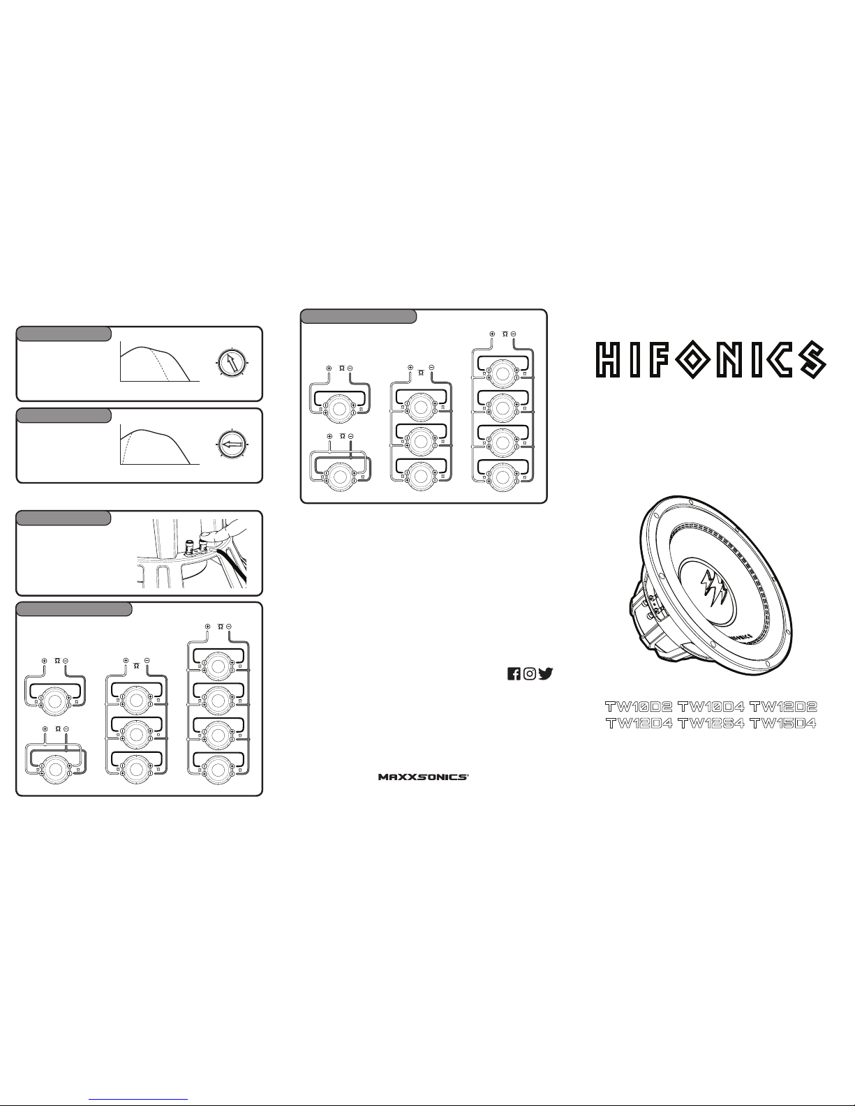
A Low pass lter will allow only
the bass frequencies to reach the
woofer making for a more natural
transition to the higher frequency
drivers. Check your amplier’s
manual for details.
We recommend using an
electronic subsonic lter. This will
help to protect the woofer from
extreme low frequency distortion.
Many ampliers are equipped
with this type lter. Check your
amplier’s manual for details.
This subwoofer is equipped with
push and insert type terminals.
Strip back 1/2” wire insulation.
Push down on the terminal, then
insert the wire and release.
Depending on the number of woofers you intend to use,
you can congure the wiring to provide the best impedance
load for your system. Below are some examples. Consult
your amplier’s manual for recommendations.
Low Pass (LPF)
Subsonic
4Ohm DVC Congurations
Connections
Crossovers
Wiring
4 4
8
4 4
2
4 4
2
4 4
2
2.7
4 4
4 4
4 4
4 4
4 4
4 4
4 4
2
4 4
4 4
4 4
4 4
2
4 4
2
4 4
2
35 250Hz
LPF
35 250Hz
LPF
15 35Hz
SUBSONIC
10Hz 100Hz 1000Hz
10Hz 100Hz 1000Hz
10Hz 100Hz 1000Hz
Depending on the number of woofers you intend to use,
you can congure the wiring to provide the best impedance
load for your system. Below are some examples. Consult
your amplier’s manual for recommendations.
2Ohm DVC Congurations
4 4
8
2 2
4
4 4
2
2.7
4 4
4 4
4 4
4 4
2
4 4
2
2.7
4 4
4 4
4 4
4 4
4 4
4 4
4 4
2
2 2
1
1.4
2 2
2 2
2 2
2 2
1
2
2
2
2
2
2
4 4
4 4
4 4
4 4
2
2 2
1
2
2
2
2
2
2
4 4
2
2.7
4 4
4 4
4 4
4 4
4 4
4 4
4 4
2
2 2
1
2 2
1
Visit Hifonics.com
 Loading...