

Hifonics ODIN 2K, CYCLOPS 3K Product Manual

AMPLIFIERS
ODIN 2K & CYCLOPS 3K
Products Manual

2 3
A. General Installation Procedure
HIFONICS MT. OLYMPUS
HIGH PERFORMANCE AMPLIFIERS
The MT OLYMPUS Series products have been designed to a very high level of performance, with features
unavailable in any other product. All of the ampliers have variable crossovers built in, with added touches
such as subsonic lter, parametric bass equalization and a remote control module that allows the overall
Level of bass boost to be controlled from the driver’s seat.
To ensure years of listening pleasure, all ampliers have a built in diagnostic mode that will detect shorted
speaker leads, low impedance, dangerous high temperatures, DC shorts and will shut down the amplier to
help prevent damage. This series also features pre clip, soft clip and hard clip indication on the remote and
end panel of each amp to prevent damage to your audio investments.
TABLE OF CONTENTS
A. General Installation Procedure 3
B. Amplier Feature Descriptions 6
C. ODIN 2K & CYCLOPS 3K Mono Amplier Applications 8
D. Setting Up Systems to Maxximize Performance 12
E. Troubleshooting a System 14
F. Fine Tuning: Signal Processing 17
G. Specications 20
H. Maxxsonics Limited Warranty 21
Check out our videos of new products, events and technical tutorials at
WWW.YOUTUBE.COM/MAXXSONICSUSAINC
The contents of this manual may not be reproduced or copied without the written consent of
MAXXSONICS USA, Inc.
A. GENERAL INSTALLATION PROCEDURE
KEYS TO SUCCESS
Follow these keys to success for your amplier installation for reduced system noise and great
sound quality.
» Separate Power/Ground & RCA - Make sure that Power/Ground and RCA signal cables are at least
18” apart. Consider running Power/Ground on one side of the vehicle and RCA signal on the other.
» Quality Cables - Use the highest quality RCA, Power and Ground Cables. Choosing great ampliers
is only part of the installation. Use quality, connectors throughout the system to assure great sound and
reduced injected noise from the vehicles electrical system.
» Chassis Ground - Never use factory screws or bolts to electrically ground ampliers. Use a short
(less than 18”) 0-gauge wire for Cyclops 3K or a 4-gauge wire for Odin 2K with a ring terminal or
grounding distribution block. Remove paint and secure amplier grounds directly to the chassis of the
vehicle.
» Proper Power & Fuse - Assure that you have fused each amplier with the appropriate fuse within 12”
of the vehicles battery.
SYSTEM DESIGN
The success of any car stereo system relies on several factors, such as the system design, execution of the
installation, and system setup. Remember that any system is only as good as its weakest link.
It is important to know that higher power systems or ampliers are not only useful for high sound pressure
levels (SPL) but also to establish headroom capability for an audio system. Headroom means that a system
to be able to reproduce musical peaks cleanly without distortion. Lower power ampliers will clip earlier
than their more powerful cousins, and cause loudspeaker failure when overdriven due to the harmonics
generated by a clipped signal, thus overheating voice coils.
Ampliers should be mounted with the ns running horizontally for best convection cooling, to minimize
overheating. Choose the best quality RCA cables for reliability and less engine noise interference in through
the audio system.
4 5
A. General Installation Procedure
A. General Installation Procedure
INSTALLATION
It is highly recommended that the amplier be mounted to a board of MDF or other solid structure using the
4 mounting screws provided. Avoid mounting the amplier to metal as this can introduce noise and other
unwanted issues. When mounting the amplier, ensure that it is mounted HORIZONTALLY for optimal heat
dissipation. Mounting ampliers to speaker enclosures is not recommended as this can cause damage to
the amplier components. When choosing a location for mounting the amplier, ensure that you check for
clearance from wires, gas tank, electrical devices and brake lines etc.
Power & ground connections: (see the features matrix on page 5 for proper gauge cables per amplier)
Run the wiring so that RCA cables are at least 18“ away from power and speaker cables. Keep RCA cables
away from electrical devices in the vehicle that can cause electrical noise, such as electric fuel pumps,
emission control modules and other on-board electronic modules.
Use a sufcient gauge power cable and ground cable using the matrix on page 5 as reference to
what size wire you require. MT OLYMPUS series ampliers require at least 4 gauge power wire. In a
multi-amplier system, add the total value of the manufacturers recommended fusing to get your total system
amperage. Some applications may require multiple runs of power wire to meet the system requirements.
In multi-amplier systems it is advisable to mount a large enough fuse right at the battery, and run one or
multiple +12 volt power cables to a fused distribution block near the ampliers. It is then a simple matter to
connect the +12 volt terminal of each amplier to the distribution block. During this process, please ensure
that the main power fuse is removed to avoid shorting the electrical system. The main fuse must be within
12” of the vehicles battery.
Ground each amplier with as short a ground lead as possible directly to the vehicle chassis using at least
4 gauge wire or equivalent to the size of the ampliers’ power wire. Use a ground distribution block, if you
wish, but it is extremely important to keep the main ground lead from this distribution block to the chassis
as short as possible, not more than 18“. The ground connection integrity to the chassis is very important,
and the best way to achieve a good, solid electrical and mechanical contact is to use a large round crimp
lug, crimped and soldered to the ground cable. The next step is to scrape the paint off the vehicle chassis,
slightly larger than the ground lug, at the connection point. Drill a clearance hole in the chassis, the same
size as the lug hole, and use a bolt, spring washer and nut to securely fasten the ground lug. Use petroleum
jelly to coat the bolt/lug connection, to prevent oxidization over time.
TIP: Use the same approach when installing head units, equalizers or any audio equipment for that
matter - run short individual grounds from each piece directly to the vehicle chassis, to minimize
ground loops and system noise. All power, ground and speaker connections should be crimped and
soldered for reliability. Make sure that none of the cable insulation can chafe against exposed metal
in the vehicle, causing short circuits to the chassis.
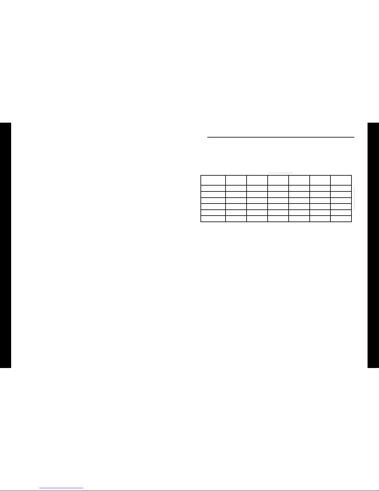
WIRE LENGTH
SYSTEM
AMPERAGE
7 - 10 ft. 10 - 13 ft. 13 - 16 ft. 16 - 19 ft. 19 - 22 ft. 22 - 28 ft.
WIRE GAUGE
35 - 50 8 6 4 4 4 4
50 - 65 6 4 4 4 4 2
68 - 85 4 4 2 2 2 0
85 - 105 4 2 2 2 2 0
105 - 125 4 2 0 0 0 0
125 - 150 2 0 0 0 0 0
NOTE: This Matrix is a general rule of thumb. Please refer to the manufacturers specic requirements.
MT OLYMPUS specications can be found on page 20.
Safe connection sequence:
After all cables are run, connect speaker wires to the speakers and ampliers, then run and plug in RCA
cables. Next, connect all power, ground, and remote turn on leads. Now, connect all +12 volt cables to the
amplier or ampliers and distribution blocks and fuse holders. Finally, connect the main +12 volt cable to
the battery, with the main fuse removed. We are almost ready to power up the system.
Power up the system:
The following procedure may seem like overkill, but there is nothing more frustrating when turning on a
system for the rst time, and it does not work properly immediately.
First, make sure the head unit is off, and turn all level controls to minimum (counterclockwise), including
the head unit volume control. Set all equalizers to 0 dB (no boost), and all crossover frequency controls at
approximate frequencies, as recommended by the loudspeaker manufacturer. Set all input selector and
crossover switches as required for the application. Remove all amplier fuses, and insert the main fuse at
the battery. If the fuse does not blow, you can insert the fuse in one of the ampliers, and we are ready to
turn on the system. Turn the head unit on, insert a CD, or select a radio station, and increase the head unit
volume control. If the system sounds ne, turn off the head unit, and install fuses in the remaining ampliers,
one by one, until the complete system is powered up and functioning properly.
6 7
B. Amplifier Feature Descriptions
B. Amplifier Feature Descriptions
REMOTE
Designed and Engineered in the U.S.A.
INPUT OUTPUT
L L
R R
MASTER
OUT
SLAVE IN
SEE OWNERS MANUAL
FOR DIAGNOSTIC CODES
PROTECT
POWER
MST SLV
MODEPHASE
9V 0.2V 0 180
LEVEL
15 35Hz
SUBSONIC
35 250Hz
LPF
BASS EQ
30 100Hz0 10dB
BOOST WIDTH CENTER
B. AMPLIFIER FEATURE DESCRIPTIONS
MT. OLYMPUS AMPLIFIERS
Mt. Olympus is a unique series of ampliers regarding channel stability and design.
NOTE: THIS MANUAL FEATURES THE AMPLIFIERS ODIN 2K AND CYCLOPS 3K ONLY
» The COLOSSUS and COLOSSUS PRO are stable at 4/2/1-Ohm per channel and 4/2-Ohms bridged.
» The BOLTAR and JUPITER are stable at 4/2-Ohms per channel and 4-Ohms bridged.
» The HERCULES and ATLAS is stable at 4/2/1-Ohm.
» The ODIN 2K and CYCLOPS 3K are stable at 4/2/1-Ohm.
» The input sensitivities for rated output powers are variable from 0.2V to 9V.
» All crossovers are fully variable in their respective ranges.
» Crossover lters are 12dB/Octave.
» A green POWER LED indicates the powered up and turned on condition.
» All HIFONICS ampliers feature a comprehensive diagnostic system, with speaker lead short circuit,
and amplier DC faults indicated by the red “PROTECT” LED.
CAUTION: DO NOT OPERATE ANY AMPLIFIER BELOW THE INTENDED IMPEDANCE. THIS
WILL CAUSE DAMAGE TO THE AMPLIFIER THAT WILL NOT BE COVERED UNDER THE
WARRANTY PRINTED IN THIS MANUAL.
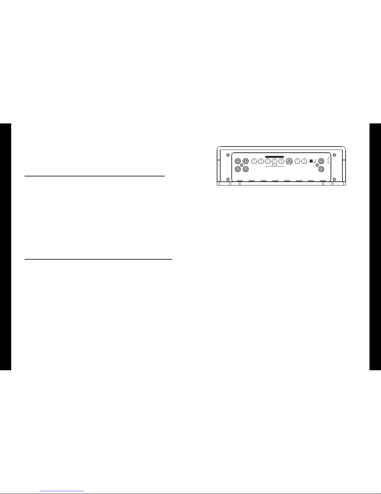
FEATURES FOR ODIN 2K & CYCLOPS 3K
These ampliers feature two DIAGNOSTIC LED’s. One monitors Short Circuits and Thermal Protection while
the second monitors Clipping status.
» INPUT: RCA Inputs receives signal from the source unit.
» OUTPUT: Passes full range signal through the amplier unchanged by settings on the amplier. Use
these set of RCA’s to reduce the need for muliple runs of cable to the amplier installation location.
» LEVEL: This is the input level used to balance the amplier with the voltage from the source unit.
Voltage is variable from 0.2V to 9V.
» PHASE: Variable time alignment from 0 to 180 degrees.
» BASS EQ: PARAMETRIC
• BOOST: 0 to +10dB. Will enhance bass the FREQUENCY selected.
• WIDTH: Narrow to Wide range enhancements above and below the center FREQUENCY.
• CENTER: Variable center frequency from 30Hz to 100Hz.
» REMOTE: Plug in the bass remote to this port.
» SUBSONIC FILTER: Low frequency cutoff variable from 15Hz to 35Hz.
» LOW PASS FILTER: High frequency cutoff variable from 35Hz to 250Hz.
» MODE: (ODIN 2K & CYCLOPS 3K):
• MST (MASTER): Factory setting for the switch location when using the amp alone is always set to
MST. Also used when linking a pair of either the ODIN 2K or CYCLOPS 3K ampliers. When in MST
position, a single RCA can be connected to the MASTER OUT RCA receptacle to provide signal to
the SLAVE INPUT on the SLAVE amplier.
• SLV (SLAVE): Your MODE switch should only be in this position if you are linking a pair of ODIN
2K or CYCLOPS 3K ampliers and one of them will be the SLAVE. At that point the SLAVE amp will
receive the single RCA on the SLAVE IN. No other RCA’s can be connected to your amplier other
than SLAVE IN when in SLAVE IN position.
» PROTECT & POWER: These indictors tell you the status of the amplier.
 Loading...