

Hifonics HIF-STG3-1 Installation Manual
1
HIF-STG3-1
STAGE 3, 1000 WATT FIVE SPEAKER
RZR Tuned Audio Package
Installation Manual
For additional technical information on this and all HIFONICS products, go to the “SUPPORT” tab at HIFONICS.com
There you will find helpful, FAQ, TEQ Tips and you can contact Technical Support via email.
©2018 Maxxsonics USA
INTRODUCTION
HIFONICS STAGE 3 RZR TUNED AUDIO SYSTEM
Thanks for choosing HIFONICS. This RZR Tuned Audio System has been meticulously
engineered to install into your vehicle. We have made the process so simple you will be in and
out of the installation in about 3.5 hours.
This manual is laid out in CHAPTERS, for the STAGE 5, there are 20 CHAPTERS in total.
Within each CHAPTER there may or not be STEPS. Do them in the order presented to avoid
mistakes and frustration.
UPGRADES
The up-arrow denotes an upgrade to your STAGE
system is available. Different STAGE systems will
be denoted within the CHAPTERS. You can
always upgrade STAGE 3 and 2 to add rear pods
or the subwoofer to a STAGE 5.
2
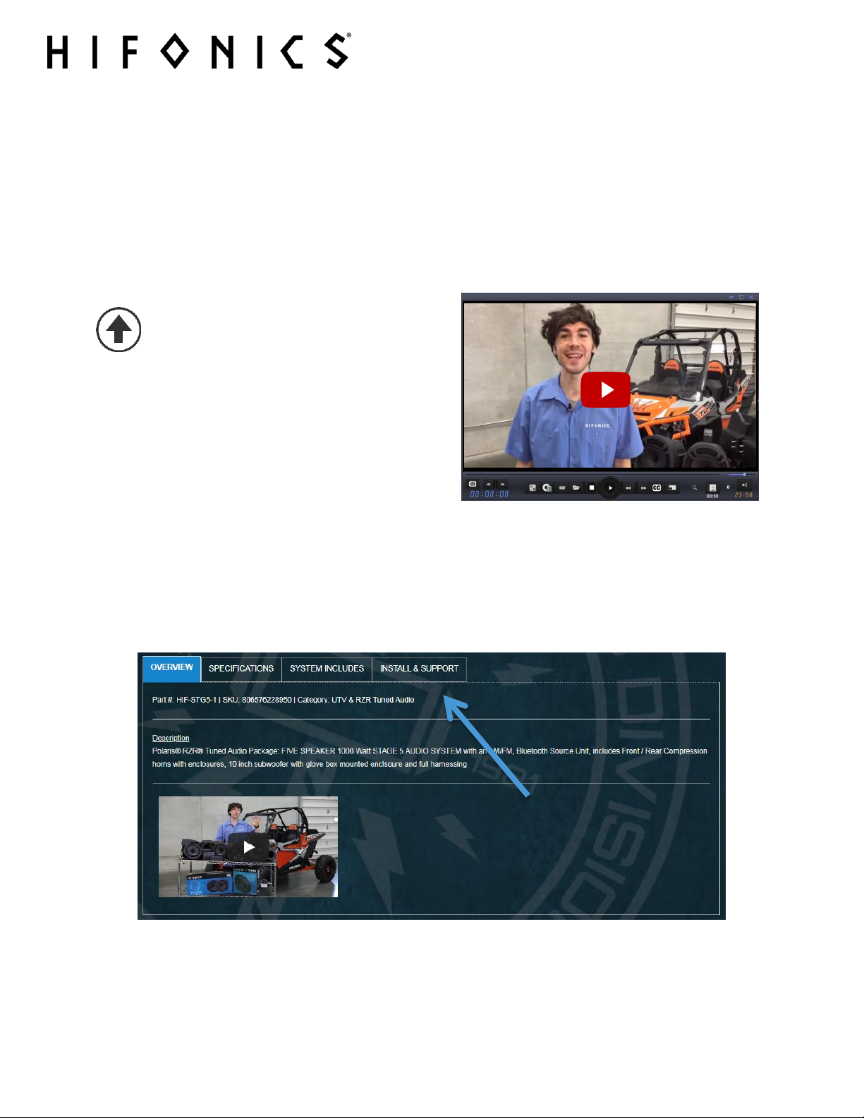
INSTALL VIDEO
We strive to create a companion “how to” install video for most of our systems. The video will
have additional details on making your installation a breeze.
If available, you can locate your specific video on the website. Just type in your model number
in the search box and then look on the INSTALL & SUPPORT tab.
For additional technical information on this and all HIFONICS products, go to the “SUPPORT” tab at HIFONICS.com
There you will find helpful, FAQ, TEQ Tips and you can contact Technical Support via email.
©2018 Maxxsonics USA

WARRANTY
Your audio system is covered by a 1 year warranty from the date of invoice. It is important that
you keep your sales receipt. Furthermore, it is crucial that you record and store a record of the
serial numbers for each of the components that are included in your system. In the rare instance
that a warranty claim is needed both proof of purchase and serial numbers are required.
Additional information is on the back page.
A) Sales Receipts show: the seller, date of purchase, model and price paid
B) Serial numbers for the components
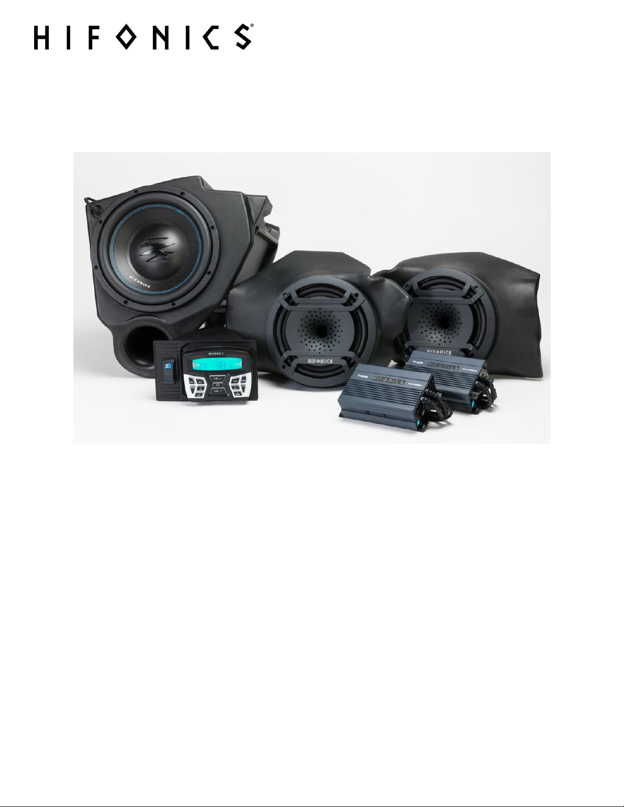
INCLUDED
The STG5 system ships in two boxes. Make sure to account for all components before
attempting installation.
Box 1
AM/FM, Bluetooth Source Unit with a mounting adapter
Compact 2 channel amplifier
Dual Amplifier Harness with mounting hardware
Dual Amplifier Mounting Plate
Kick Panel Pods
Two cage mounted 8 inch Compression Horn Tower Speakers
Two 8 inch compression horns (kick panel speakers)
Two compression element diaphragm covers with instructional manual
USB and 3.5mm dash mount input accessory
2 black swivel mount brackets for cage mounting tower speakers
3
Box 2
Compact mono subwoofer amplifier
10 inch subwoofer
Glove box replacement vented subwoofer enclosure
If you feel something is missing, please contact Maxxsonics directly via email –
support@maxxsonics.com
NOTE – Hardware for mounting components to enclosures and other items you
will need are packed within the packaging for each piece. Do not dispose of any
packaging until you have completely installed your system and certain you have
accounted for every piece.
For additional technical information on this and all HIFONICS products, go to the “SUPPORT” tab at HIFONICS.com
There you will find helpful, FAQ, TEQ Tips and you can contact Technical Support via email.
©2018 Maxxsonics USA
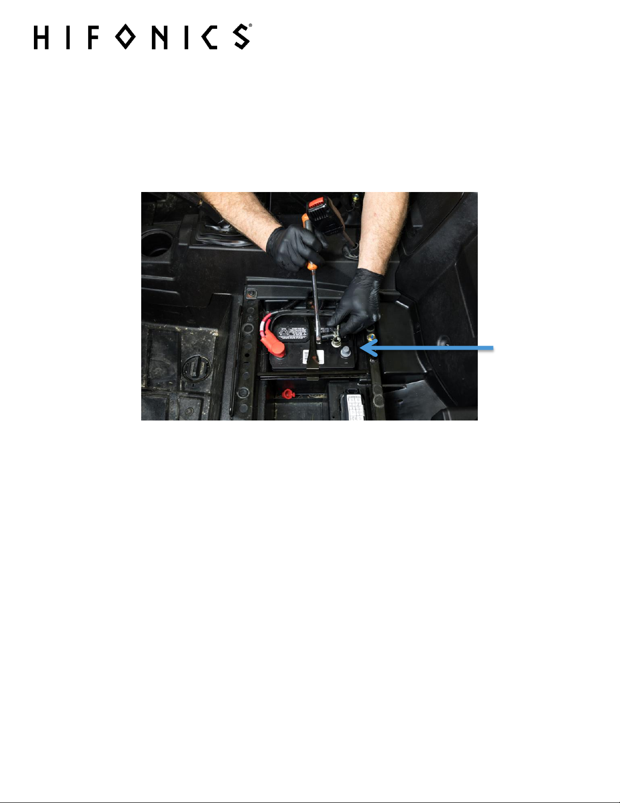
SAFETY
Prepare your machine to safely work on it and add accessories.
Turn the ignition off and remove the key
Remove the negative terminal of the battery (FIG S-1)
Use a packing blanket other soft material to protect your machine
Safety Glasses - always wear eye protection
4
(FIG S–1)
For additional technical information on this and all HIFONICS products, go to the “SUPPORT” tab at HIFONICS.com
There you will find helpful, FAQ, TEQ Tips and you can contact Technical Support via email.
©2018 Maxxsonics USA

TIME & TOOLS
You will need about 3.5 HOURS to complete this installation depending on who is “helping.”
The following are a list of tools you will need for any of the Hifonics UTV/RZR Tuned Audio
packages. Depending on which system you are installing, you may or may not need all of them.
You might also find you own more specialized tools to get the job done. Share the pics of your
installation on our social channels to help others.
Besides the tools listed, you will also find it helpful to have some music ready for the TEST &
TUNE step. We recommend:
USB with Music pre-loaded
Bluetooth Device like a phone with music or music app
TOOLS YOU WILL NEED
5
Wire Strippers and Crimpers
5/16” Drill Bit
Drill
Blue Painters Tape
Marker
½” Open Box Wrench
½” Socket (preferably deep)
10mm Socket
Ratchet
T25 Torx Driver
T40 Torx Driver
Bojo Tools (Pry Tools)
Flush cut wire cutters (Zip Ties snipping)
1 Friend
For additional technical information on this and all HIFONICS products, go to the “SUPPORT” tab at HIFONICS.com
There you will find helpful, FAQ, TEQ Tips and you can contact Technical Support via email.
©2018 Maxxsonics USA

6
CHAPTER 1 – PREPARATION FOR INSTALLATION
Before you start dismantling your machine, we suggest you prepare all your components,
enclosures and harnesses.
These steps will follow the CHAPTERS of the Installation Videos when completed. Additionally,
it will make life less stressful to have everything ready when you are ready to put each
component into the machine.
STEP 1 – CONFIRMING POWER TO BUS BAR
The Polaris RZR and our Tuned Audio System requires a harness that connects the battery
under the seat to the busbar harness that is located under the hood.
The harness is shown in FIG 1-1. Check that your machine has this harness installed. If not, you
can purchase from your dealer or Polaris online. The part numbers are 2881551 or 2881646
depending on which machine you own.
(FIG 1-1)
For additional technical information on this and all HIFONICS products, go to the “SUPPORT” tab at HIFONICS.com
There you will find helpful, FAQ, TEQ Tips and you can contact Technical Support via email.
©2018 Maxxsonics USA
PREPARATION
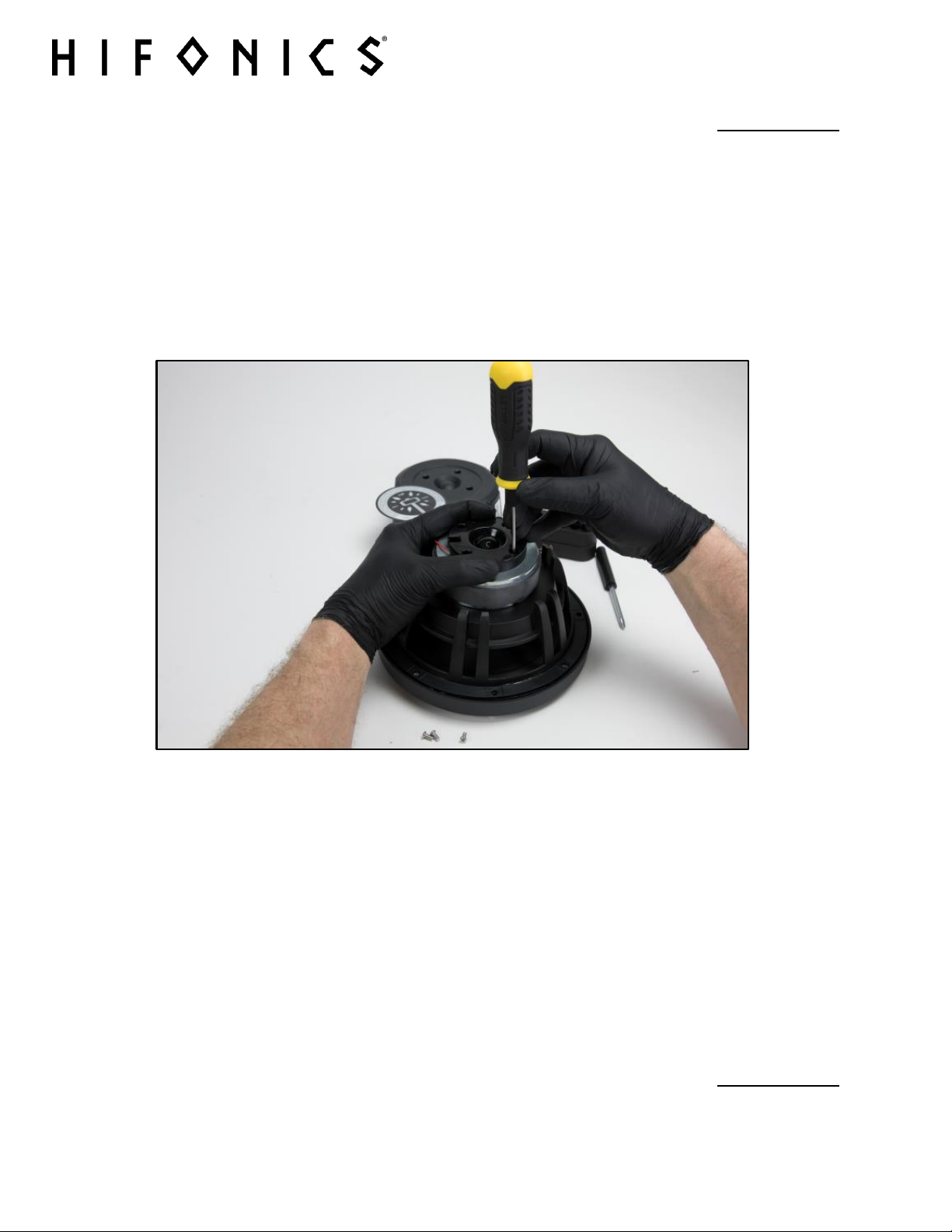
CHAPTER 2 – PREPARE YOUR KICK PANEL COMPRESSION HORNS
NOTE - Do not proceed with CHAPTER 3 until you have properly prepared the
speakers with their compression diaphragm covers. Refer to the manual called
HIF-POD. You can also find this manual on-line by searching the model number.
Shown in FIG 2-1 is one picture from the HIF-POD manual which will guide you step-by-step
through preparing the kick panel compression horn speakers for installation into the kick panel
enclosure and the RZR.
7
(FIG 2-1)
Removing the large back plate and installing the special compression horn diaphragm covers
dramatically reduces the depth of the compression horns which ultimately allows our overall kick
panel enclosure to be shallower than you would think. This assures maximum leg room for
driver and passenger in the vehicle.
PREPARATION
For additional technical information on this and all HIFONICS products, go to the “SUPPORT” tab at HIFONICS.com
There you will find helpful, FAQ, TEQ Tips and you can contact Technical Support via email.
©2018 Maxxsonics USA

CHAPTER 3 - PREP SUBWOOFER ENCLOSURE & MOUNT
If your subwoofer is not preinstalled in the enclosure, you will need to prepare the unit by
installing the clips that will hold the door from your OEM glove box.
Next you will wire the subwoofers two voice coils and screw the subwoofer to the enclosure.
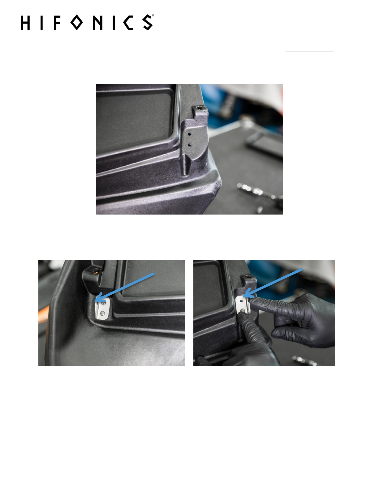
STEP 1 – MOUNT CLIPS
Mount the included hinge brackets for the OEM glove box door to be fitted on to
your subwoofer as shown in FIG 3-1 through 3-4.
8
(FIG 3-1)
For additional technical information on this and all HIFONICS products, go to the “SUPPORT” tab at HIFONICS.com
There you will find helpful, FAQ, TEQ Tips and you can contact Technical Support via email.
©2018 Maxxsonics USA
PREPARATION
Use the provided nuts to secure the hinge brackets from the inside of the subwoofer.
Do not over tighten.
9
(FIG 3-2)
The clip with the closed hole mounts on the driver side with the screws on the inside where the
glove box door will cover the screws.
(FIG 3-3) (FIG 3-4)
The hinge clip with the open hole mounts on the passenger side with the screws on the inside
where the door will cover the screws shown above
For additional technical information on this and all HIFONICS products, go to the “SUPPORT” tab at HIFONICS.com
There you will find helpful, FAQ, TEQ Tips and you can contact Technical Support via email.
©2018 Maxxsonics USA
PREPARATION
CHAPTER 4 – SUBWOOFER INSTALL INTO ENCLOSURE
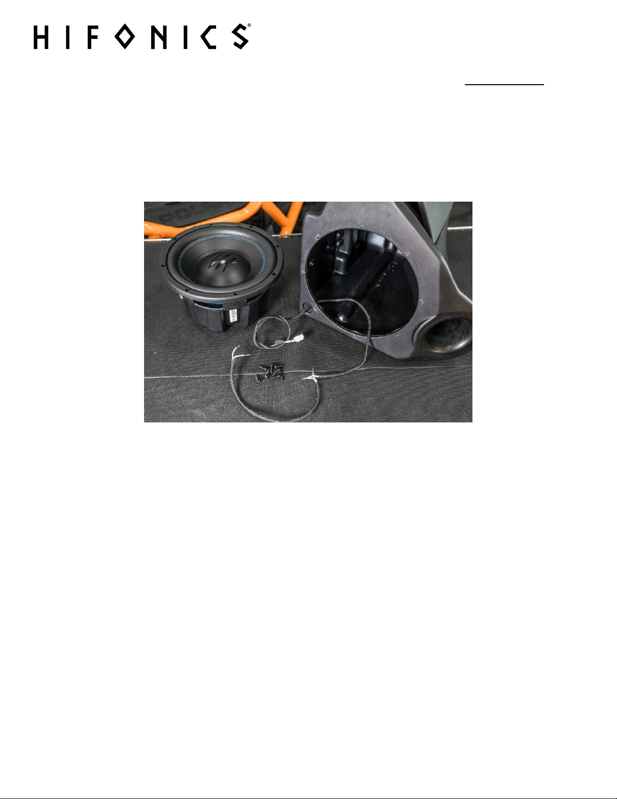
STEP 1 – INSTALL THE SUBWOOFER
Set your subwoofer enclosure on a flat surface as shown in FIG 4-1 Put the subwoofer
enclosure on its back and extend the harness from inside the enclosure as shown
in FIG 4-1.
10
(FIG 4-1)
For additional technical information on this and all HIFONICS products, go to the “SUPPORT” tab at HIFONICS.com
There you will find helpful, FAQ, TEQ Tips and you can contact Technical Support via email.
©2018 Maxxsonics USA
11
PREPARATION
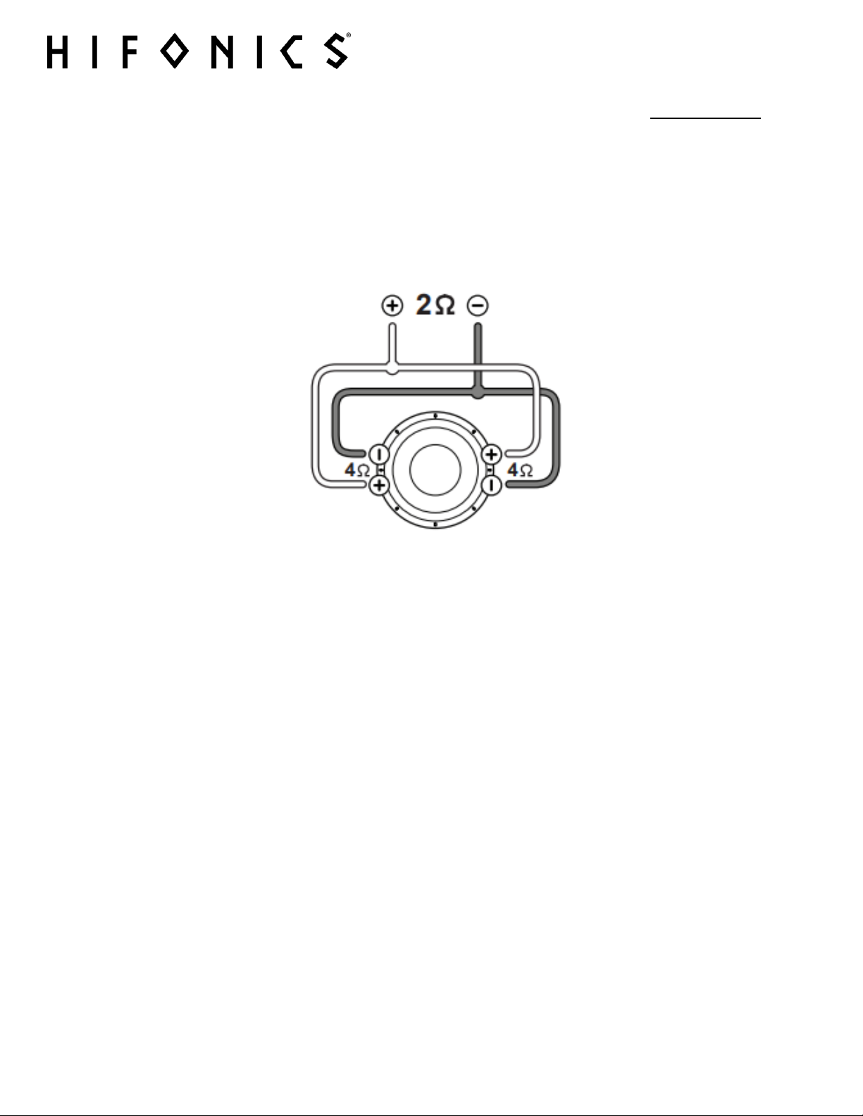
If your subwoofer was not preinstalled, you will wire the woofer with the dual voice coils to 2
ohms (indicated with the Ω symbol) as pictured in FIG 4-2. We have prepared the internal
harness so you cannot make a mistake. Wiring the subwoofer for 2 ohms (2Ω) will allow the
subwoofer to develop maxximum power from the amplifier by perfectly balancing the impedance
with the amplifiers power output.
(FIG 4-2)
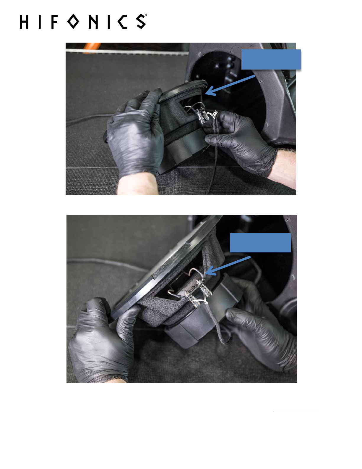
Use the connection where two wires will insert into one voice coil connector and then route the
other end of the wire to opposite connector, shown in FIG 4-3 and FIG 4-4.
NOTE – Wiring code is solid white connects to the (+) Red terminal
and White/Black Stripe connects to the (-) Negative
To open the terminals push down on the connector to open, push the soldered ends through the
hole and release the connector to establish a good electrical connection.
For additional technical information on this and all HIFONICS products, go to the “SUPPORT” tab at HIFONICS.com
There you will find helpful, FAQ, TEQ Tips and you can contact Technical Support via email.
©2018 Maxxsonics USA
12
DUAL WIRE ON
ONE CONNECTOR
SINGLE WIRE
OPPOSITE CONNECTOR
(FIG 4-3)
For additional technical information on this and all HIFONICS products, go to the “SUPPORT” tab at HIFONICS.com
(FIG 4-4)
PREPARATION
There you will find helpful, FAQ, TEQ Tips and you can contact Technical Support via email.
©2018 Maxxsonics USA
13
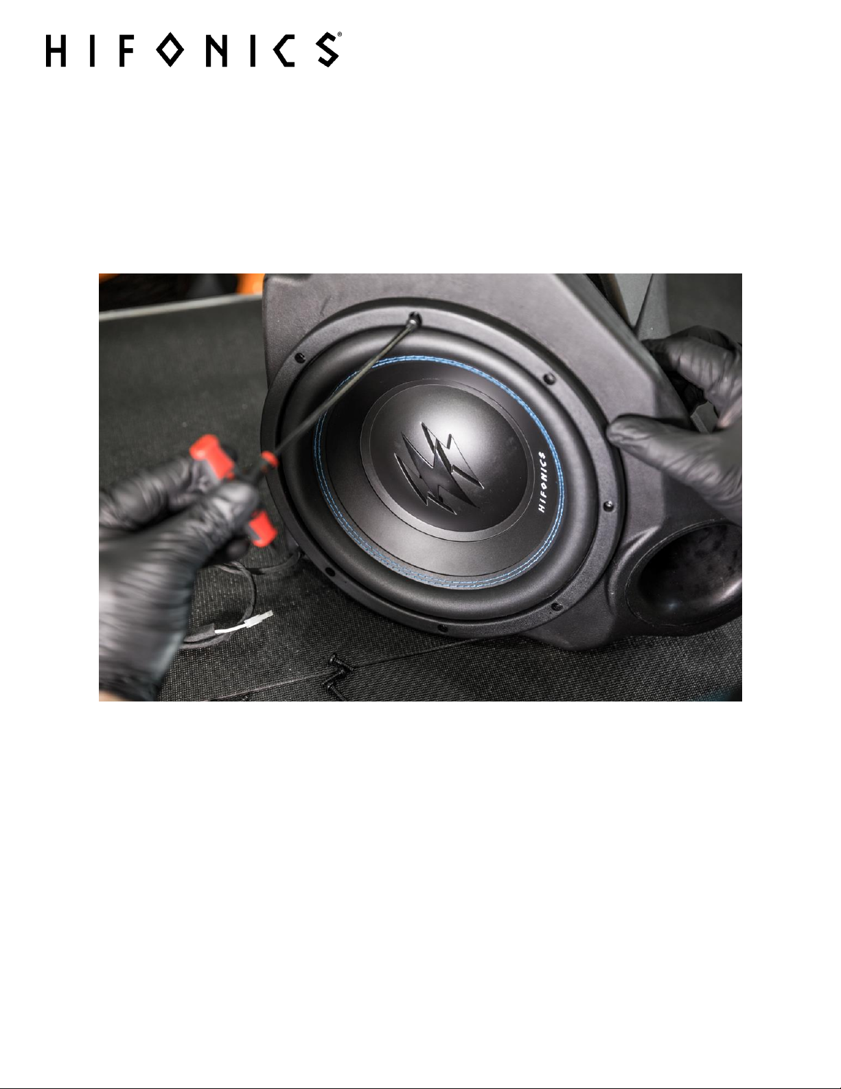
STEP 2 – SECURE THE SUBWOOFER TO THE ENCLOSURE
Due to the shape of the enclosure it can be very difficult to balance the subwoofer enclosure
and screw in the speaker for one person shown in FIG 4-6.
Consider having a friend hold the enclosure steady while you mount the subwoofer using HAND
TOOLS with the screws provided.
(FIG 4-6)
For additional technical information on this and all HIFONICS products, go to the “SUPPORT” tab at HIFONICS.com
There you will find helpful, FAQ, TEQ Tips and you can contact Technical Support via email.
©2018 Maxxsonics USA
PREPARATION
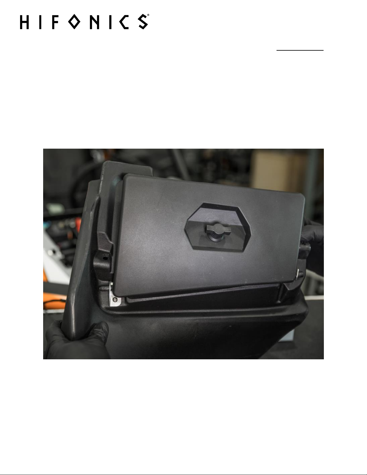
CHAPTER 5 – REMOVE & REINSTALL THE GLOVE BOX DOOR
With a small amount of pressure you can bend up on the center portion of your OEM glove box
door and remove it from the brackets.
In a reverse movement you can now reinstall this door onto your new subwoofer glove box to
give your subwoofer a stealth appearance as shown in FIG 5-1.
The subwoofer is now complete. Set aside until installation and wiring.
14
(FIG 5-1)
For additional technical information on this and all HIFONICS products, go to the “SUPPORT” tab at HIFONICS.com
There you will find helpful, FAQ, TEQ Tips and you can contact Technical Support via email.
©2018 Maxxsonics USA

VEHICLE DISMANTLE
CHAPTER 6 - VEHICLE DISASSEMBLY
STEP 1 – REMOVE HOOD
Start with removing the hood. This is where you will access the bus bar (FIG 6-1). Confirm that
your machine has the busbar installed by the dealer or by you. If your busbar harness has not
been installed, see Chapter 1 of this manual for clarification
15
(FIG 6-1)
For additional technical information on this and all HIFONICS products, go to the “SUPPORT” tab at HIFONICS.com
There you will find helpful, FAQ, TEQ Tips and you can contact Technical Support via email.
©2018 Maxxsonics USA
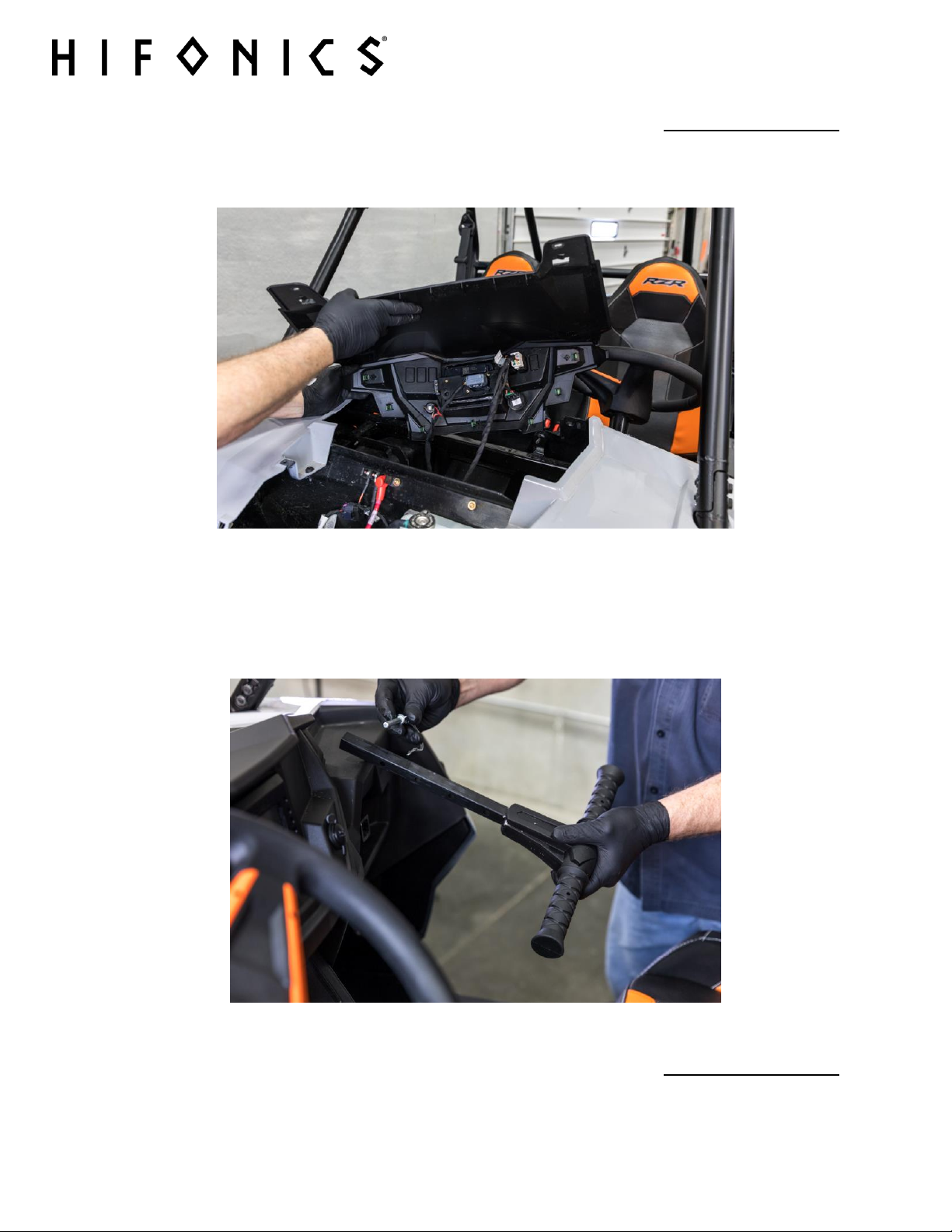
STEP 2 - REMOVE TOP OF DASH
Remove the top of the dash shown in FIG 6-2 by removing the screws
16
VEHICLE DISMANTLE
(FIG 6-2)
STEP 3 – REMOVE THE GRAB BAR
Remove the grab bar shown in FIG 6-3 by removing the retaining clip and pin and firmly pulling
the grip toward the rear of the vehicle.
(FIG 6-3)
VEHICLE DISMANTLE
For additional technical information on this and all HIFONICS products, go to the “SUPPORT” tab at HIFONICS.com
There you will find helpful, FAQ, TEQ Tips and you can contact Technical Support via email.
©2018 Maxxsonics USA
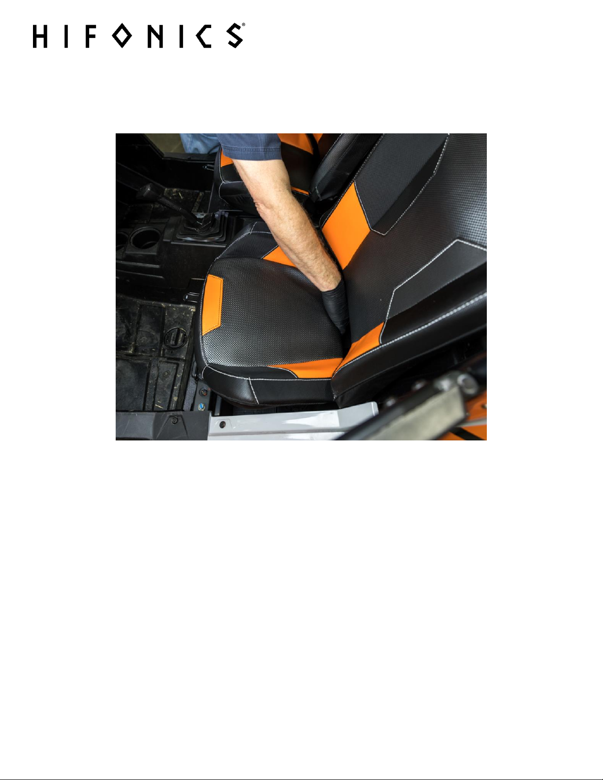
STEP 6 – REMOVE SEATS
Remove seats by pulling on the lock clip (FIG 6-4) located between the bottom and upright
portion of the seat.
17
(FIG 6-4)
Behind the seats (behind the rear seat in the 4P) in the center of the machine is the panel where
you access the oil filter. You will need to remove this in order to feed and secure the rear
speaker harness
For additional technical information on this and all HIFONICS products, go to the “SUPPORT” tab at HIFONICS.com
There you will find helpful, FAQ, TEQ Tips and you can contact Technical Support via email.
©2018 Maxxsonics USA
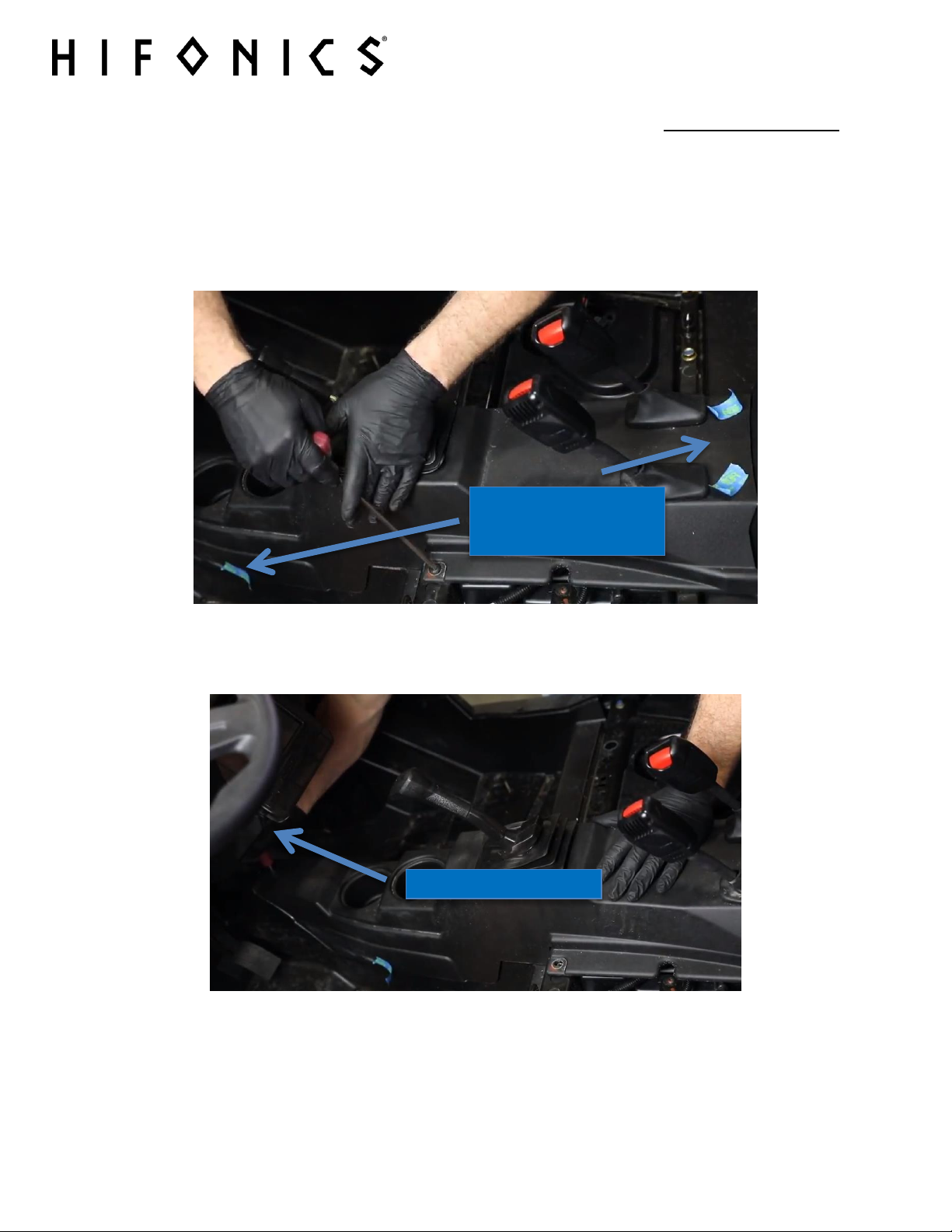
REMOVE TORX AT FRONT
USE TAPE TO MARK WHERE
SHOULD BE REPLACED
VEHICLE DISMANTLE
STEP 7 – REMOVE CENTER CONSOLE
Use the painters tape to mark where you remove each of the push pins and/or T-40 screws
shown in FIG 6-5.
It is wise to get some small disposable cups or sandwich bags to label the different screws to
keep track of them.
18
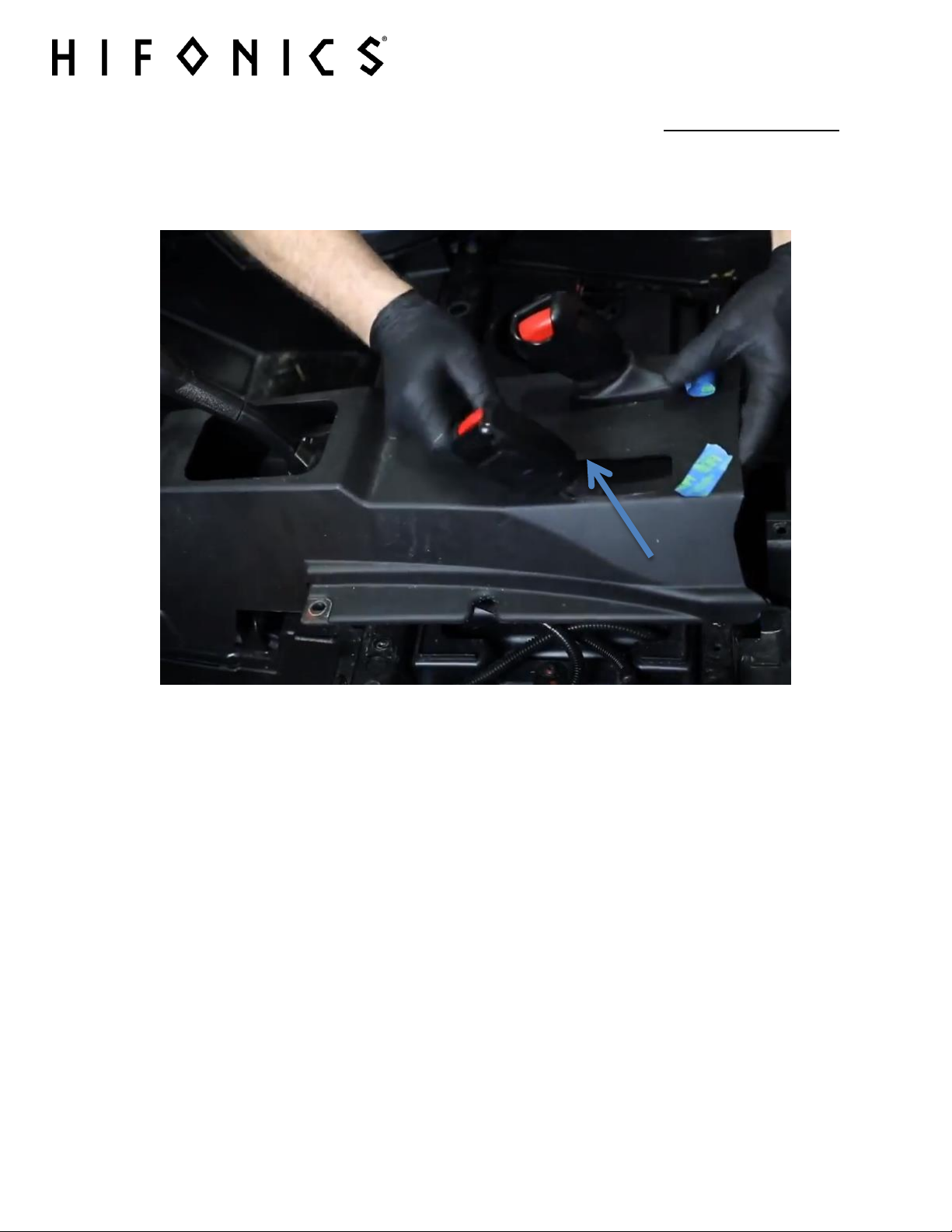
PUSH-PINS AND TORX
(FIG 6-5)
There is a T-40 at the front of the center console in the dark. Don’t miss it. FIG 6-6.
For additional technical information on this and all HIFONICS products, go to the “SUPPORT” tab at HIFONICS.com
(FIG 6-6)
There you will find helpful, FAQ, TEQ Tips and you can contact Technical Support via email.
©2018 Maxxsonics USA
VEHICLE DISMANTLE
Gently push the shifter and seat belt boots back through the console as show as shown
in FIG 6-7.
19
(FIG 6-7)
For additional technical information on this and all HIFONICS products, go to the “SUPPORT” tab at HIFONICS.com
There you will find helpful, FAQ, TEQ Tips and you can contact Technical Support via email.
©2018 Maxxsonics USA
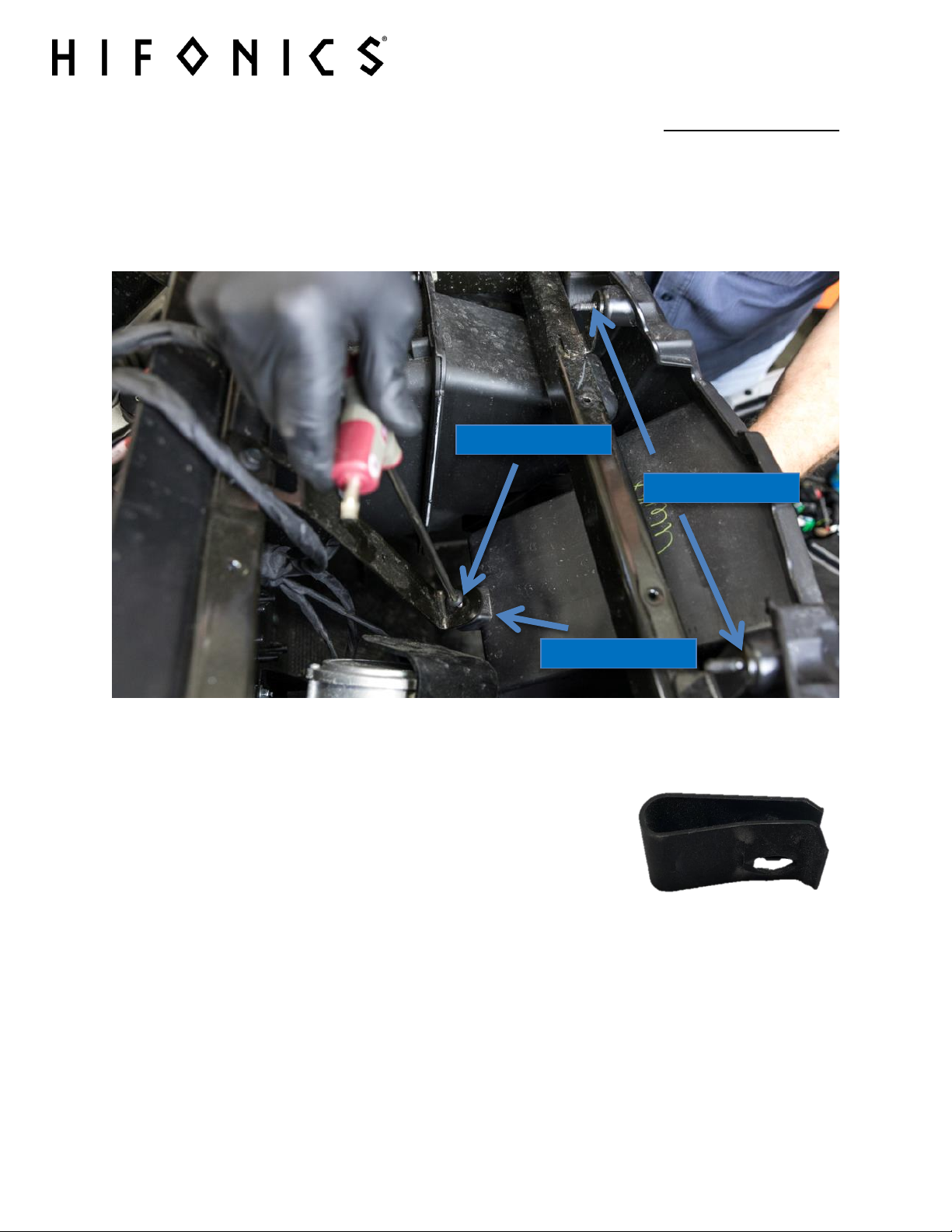
T-40 TORX
PHILLIPS SCREW
REMOVE CLIP
VEHICLE DISMANTLE
STEP 8 - PULLING DASH BOX
To remove the DIN dash box from the dash, there are three points to address. First, locate the
rear support bracket the down bracket at the rear of the pocket and remove the T-40 Torx
screw.
20
(FIG 6-8)
Remove the clip shown on the right from the back of this pocket
and set aside for re-use when mounting your new dash source
unit. You will reuse the screw that was in the OEM piece shown in
FIG 6-8.
For additional technical information on this and all HIFONICS products, go to the “SUPPORT” tab at HIFONICS.com
There you will find helpful, FAQ, TEQ Tips and you can contact Technical Support via email.
©2018 Maxxsonics USA
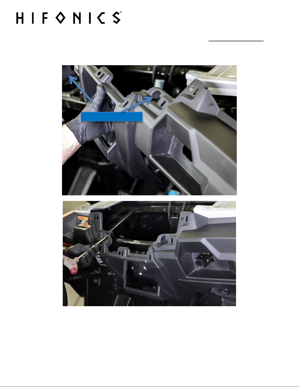
REMOVE TORX
STEP 9 – PULLING FRONT DASH
Remove 4 Torx screws from the front of the dash
21
VEHICLE DISMANTLE
For additional technical information on this and all HIFONICS products, go to the “SUPPORT” tab at HIFONICS.com
There you will find helpful, FAQ, TEQ Tips and you can contact Technical Support via email.
©2018 Maxxsonics USA
 Loading...