

Hi-Flame GloFire 905 Installation And Operating Instructions Manual

GloFire 905
Installation and Operating Instructions
Henan Hi-Flame Metal Co. Ltd., 71 Welai Rd., Zhengzhou, China 450008
Save These Instructions
Tested to UL 1482 by Intertek
U.S EPA Phase II Certified Stove

Please read this entire manual before you install and use your new room
heater. Failure to follow instructions may result in property damage, bodily
injury, or even death.
Safety Notices
When this room heater is not properly installed, a house fire may result. To reduce the
risk of fire, follow the installation instructions. Contact local building, fire officials, or
authority having jurisdiction about restrictions, permit and installation inspection
requirements in your area.
DO NOT INSTALL IN A MOBILE HOME.
DO NOT USE CHEMICALS OR FLUIDS TO START THE FIRE.
DO NOT BURN GARBAGE OR FLAMMABLE FLUIDS SUCH AS GASOLINE, NAPHTHA OR
ENGINE OIL.
HOT WHILE IN OPERATION. KEEP CHILDREN, CLOTHING AND FURNITURE AWAY.
CONTACT MAY CAUSE SKIN BURNS.
Do not tamper with or use the spin draft air control in the fuel loading door. Using this
control will cause an overtiring condition.
Page 1

INSTALLATION
Assembling the GloFire 905
1. Open the door and unfasten the wire on the fire fence. It is used to ensure that the
fire glass does not break during transportation.
2. Take the packet containing the spare parts and screws from the ash pan.
3. Fix the flue collar on the outlet which you selected by using the M6*20 flat
crosshead screw. Ensure all seals are secure to prevent air leakage. If you choose
the rear flue outlet, remove the flue cover before fixing the flue collar.
4. Fix the black handle on the stainless steel door catch with the M8*90 bolt.
5. Keep the rest of the screws and Allen wrench for future use.
Page 2
Floor Protector
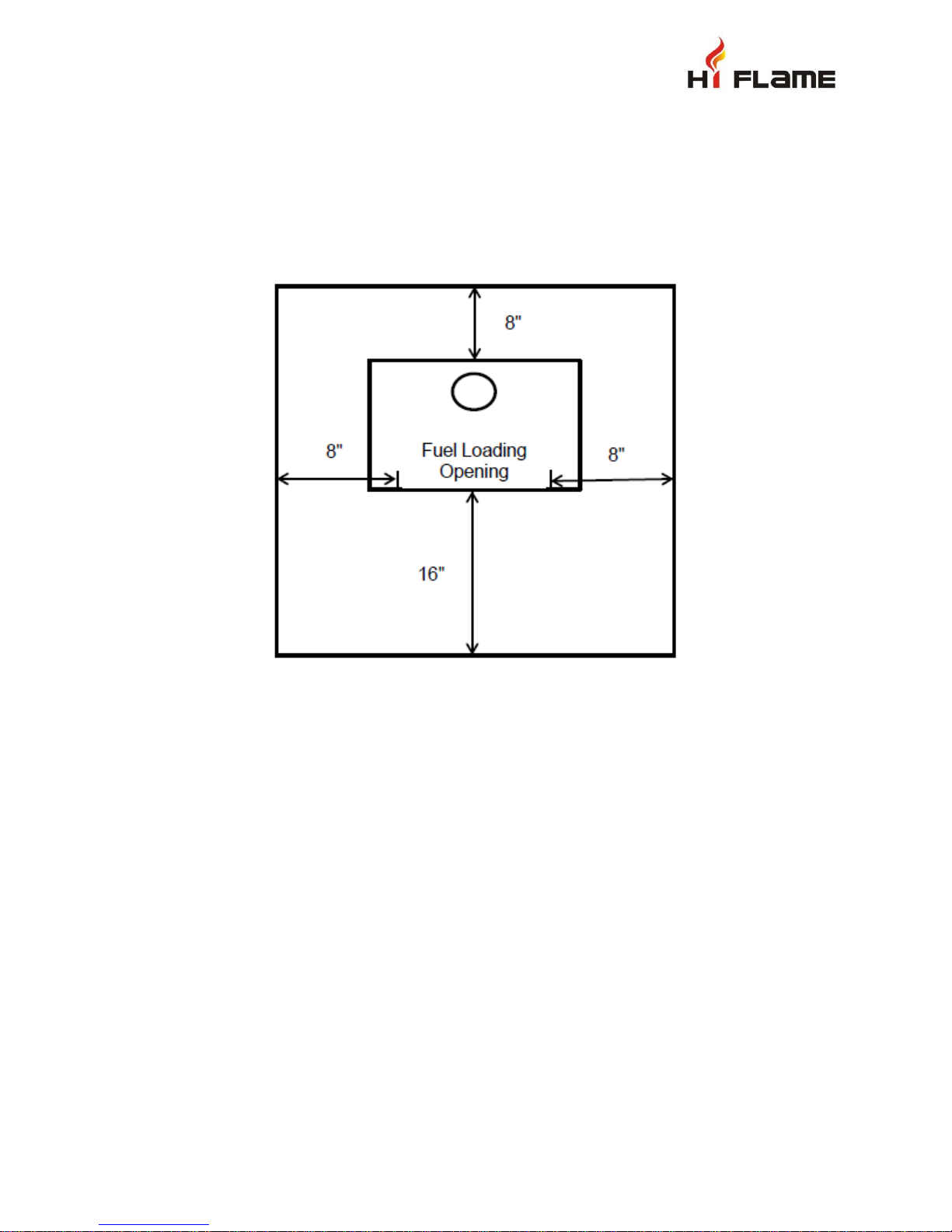
If the stove is to be installed on a combustible floor, it must be placed on an approved
1” (25mm) non-combustible hearth pad with k = 0.42 (BTU)(in)/(ft2)(hr)(oF). The floor
protector must extend 8” beyond each side of the flue loading and ash removal opening
and 16” to the front.
In a rear vent installation the floor protection must also extend under the stovepipe and
a minimum of 2” (50mm) beyond either side of the pipe.
Page 3

How to determine if alternate floor protection materials are acceptable.
893.075.0
84.0
11
xT
k
R
431.042.0
rick
R x
b
431.0125.0
29.0
1
R x
board mineral
T
k
1
R
T
12xK
1
R
Btu
)F
o
)(hr)(
2
(ft
R
12xK
)F
o
)(hr)(
2
ft(
(Btu)(in)
k
)F
o
)(hr)(
2
ft(
(Btu)(ft)
K
k
1
)in)(Btu(
)Fo)(hr)(
2
(ft
r
All floor protection must be non-combustible (i.e., metals, brick, stone, mineral fiber boards,
etc.). Any organic materials (i.e., plastics, wood paper products, etc.) are combustible and
must not be used. The floor protection specified includes some form of thermal designation
such as R-value (thermal resistance) or k-factor (thermal conductivity).
PROCEDURE:
1. Convert specification to R-value:
i. R-value given - no conversion needed.
ii. k-factor is given with a required thickness (T) in inches:
iii. K-factor is given with a required thickness (T) in inches:
iv. r-factor is given with a required thickness (T) in inches: R = r x T
2. Determine the R-value of the proposed alternate floor protector.
i. Use the formula in step (1) to convert values not expressed as “R”.
ii. For multiple layers, add R-values of each layer to determine overall R-value.
3. If the overall R-value of the system is greater than the R-value of the specified floor
protector, the alternate is acceptable.
EXAMPLE: The specified floor protector should be 3/4-inch thick material with a k-factor of
0.84. The proposed alternate is 4” brick with an r-factor of 0.2 over 1/8” mineral board with a
k-factor of 0.29.
Step (a): Use formula above to convert specification to R-value.
Step (b): Calculate R of proposed system.
4” brick of r = 0.2, therefore:
1/8” mineral board of k = 0.29, therefore
R
total
= R
brick
+ R
Step (c): Compare proposed system R
system R
is greater than required, the system is acceptable.
total
DEFINITIONS:
mineral board
= 0.8 + 0.431 = 1.231
of 1.231 to specified R of 0.893. Since proposed
total
Page 4
 Loading...