

R
R
Tel:0086-024-31682686
233020021Re v 1. 0 20 20 -0 2- 17
Shenyang RMS Medical Tech Co.,Ltd
Noninvasive Ventilator
R
C o n t e n t s
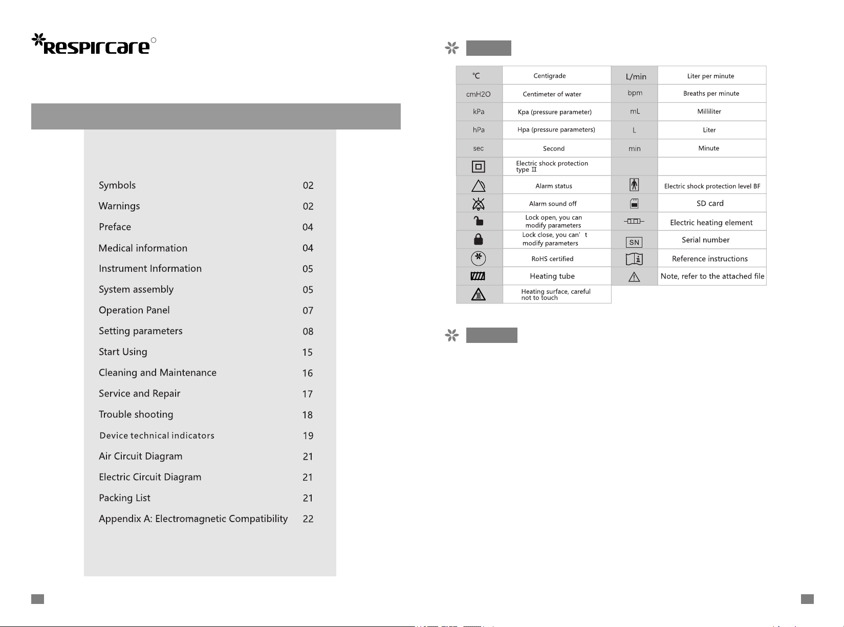
Symbols
RoHS
P
I 21
Ingress protection
Warnings
● Before using this instrument, please read the manual carefully.
● Do not use this instrument for life support.
● The instrument produces a positive airway pressure when it outputs the gas, andif positive airway
pressure has side effects to the patients, it must be considered tohandle.
● This instrument must be used and set parameters under guidance of professionaldoctors.
● Do not replace doctor's advice with recommends in the manual.
● This instrument can only use water chamber, Heated breathing tube, nasal cannulasand other
accessories provided by RMS Medical. Use of unapproved accessories may affect the functionality
of the instrument or cause a danger.
● The water chamber, Heated breathing tube,nasal cannula and other accessoriesprovided by our
instrument,it can only be used for this instrument, otherwise it mayaffect the function of other
equipments or cause danger.
● In case of power failure or machine malfunction, remove the nasal cannulas andclose the oxygen
input.
● To ensure its electromagnetic compatibility, this instrument must be installed,debugged and used
according to provisions in attached documents.
● Portable and mobile RF communication equipment may affect this instrument'selectromagnetic
compatibility. In case of such event, please contact our staff forsolutions.
● This instrument can only be connected using cables mentioned in the attacheddocument. Use of
unapproved accessories and cables for connecting theinstrument may result in increased emission
or reduced immunity.
0201
● Do not place this instrument near to or stacked with other equipment. If it is necessary to place this instrument
near to or stacked with other equipment, inspection and observation must be conducted to ensure that it can
operate normally in such location.The instrument should be placed in a well-ventilated area and not on the soft
surface.
● Do not use the instrument when it is surrounded by flammable and/or anesthetic gases.
● Stop using the instrument if it has visible external damage, a liquid has entered into the instrument or the outlet
gas is over-temperature or there is abnormal noise.
● The over-use of Heated breathing tubeand nasal cannula can cause infections and other injuries.
● When the instrument is used under specified ambient temperature and humidity conditions, the temperature of
outlet gas isless than 43℃.。
● In ventilation mode, the outlet gas may be harmful to the human body, when the room temperature exceeds 35°C.
● In humidification mode, the temperature and humidity will be affected when the ambient temperature exceeds
the specified temperature range of 18 ° C ~ 28 ° C.
● When the instrument is used beyond the specified ambient conditions (temperature, humidity etc.), the instrument
performance will be affected and even damaged and may cause body injuries.
● When the atmospheric pressure exceeds the specified range, using the ventilator may cause the set pressure to
differ from the actual pressure
● AC input should be within ±10% of the rated voltage. AC input beyond this range may cause damage to the
instrument.
● When exposed in an environment of electrocautery, electrosurgery, defibrillation, X-rays (γ-rays), infrared radiation
andtransient electromagnetic fields, including magnetic resonance (MRI) and radio interference, the instrument
may be interfered.
● When the instrument is blocking, covering or heating the outlet tube,air inlet port may cause overheating or even
damage to the instrument.
● When the instrument is connected to oxygen,it may cause higher output oxygen concentration if the output tube
is blocked.
● The ventilation holes are at the bottom of the water chamber. When moving the humidifier, do not touch the
bottom to prevent body injuries.
● Pressure and differential pressure sensors are installed inside the device. Pay attention to prevent water from
flowing backwards and causing damage.
● Do not move the instrument, place it upside down or tilt it when there is water in the humidification cup, so as to
prevent water from flowing back into the instrument which will cause damages to the instrument. Above the
humidification cup, label awarning label “Do not Tilt the Instrument When There is Water!” to have attentions.
● When the instrument is not in use, pull the plug.
● Do not open the inside of instrument,should be repaired by the authorized maintainer.
● When the treatment instrument is beyond its service life, please contact your dealer or RMS Medical for
disposition instead of discarding it arbitrarily.
● Adding other components to the respiratory ventilation system will cause the exhalation pressure at the
connection port of the patient to increase.
● Do not use antistatic or conductive hoses or tubes.
● The sensor's raw data collected by the ventilator is anti-interference processed by the median average filtering
method.
● The high-pressure gas must be connected to medical oxygen, and fresh gas cannot be used.
● It is recommended to measure the oxygen concentration at the patient's delivery end.
● The nasal cannula, Heated breathing tube, water chamber, mask, etc. equipped with the ventilator are products
registered separately by manufacturers with medical device qualifications. When using them, please refer to their
own instructions.
● Note:Above mentioned are general warnings and precautions.Detailed special warnings,notes and remarks are
shown in the manual.
Preface
BPAP H series ventilator is a breathing ventilation device that can use both non-invasivemask ventilation
and high-flow humidified airflow. Please read and understand thismanual carefully before use.
The non-invasive ventilator must be set and used for treatment parameters under theguidance of a
professional doctor.
Medical information
This product's non-invasive positive pressure ventilation mode (Ventilation mode for short) can be used
for adult patients with insufficiency of breathing, such as those who do not rely on invasive ventilation
support, to provide ventilation assistance and respiratory support; has a high-flow heating and
humidification mode (high flow mode for short) The product can be usedfor humidification and oxygen
therapy in adults with spontaneous breathing.
This product is not intended for life support, can be used in home environments, and can also be used in
medical institutions. This product needs to be used under the guidance of a professional doctor.
★ Heartbeat or breathing stops;
★ Weak spontaneous breathing and coma;
★ High risk of aspiration, inability to remove oropharyngeal and upper respiratory secretions,and poor
respiratory protection;
★ Combined with other organ failure (unstable hemodynamic indicators, unstable arrhythmia,perforation
/ hemorrhage of digestive tract, severe brain disease, etc.)
★ Undrained pneumothorax;
★ Neck and facial trauma, burns and deformities;
★ Recent face, neck, oral cavity, pharyngeal cavity, esophagus and stomach surgery;
★ upper airway obstruction;
★ Obviously uncooperative or extremely nervous;
★ Severe hypoxemia (PaO2 <45mmHg), severe acidosis (pH ≤7.20);
★ severe infection;
★ Airway secretions or sputum disorders;
★ Not recommended by other clinicians.
Note: It is a relative contraindication. In such patients, the pros and cons of NPPV (non-invasivepositive
pressure ventilation) need to be carefully weighed, then decide whether to apply NPPV;
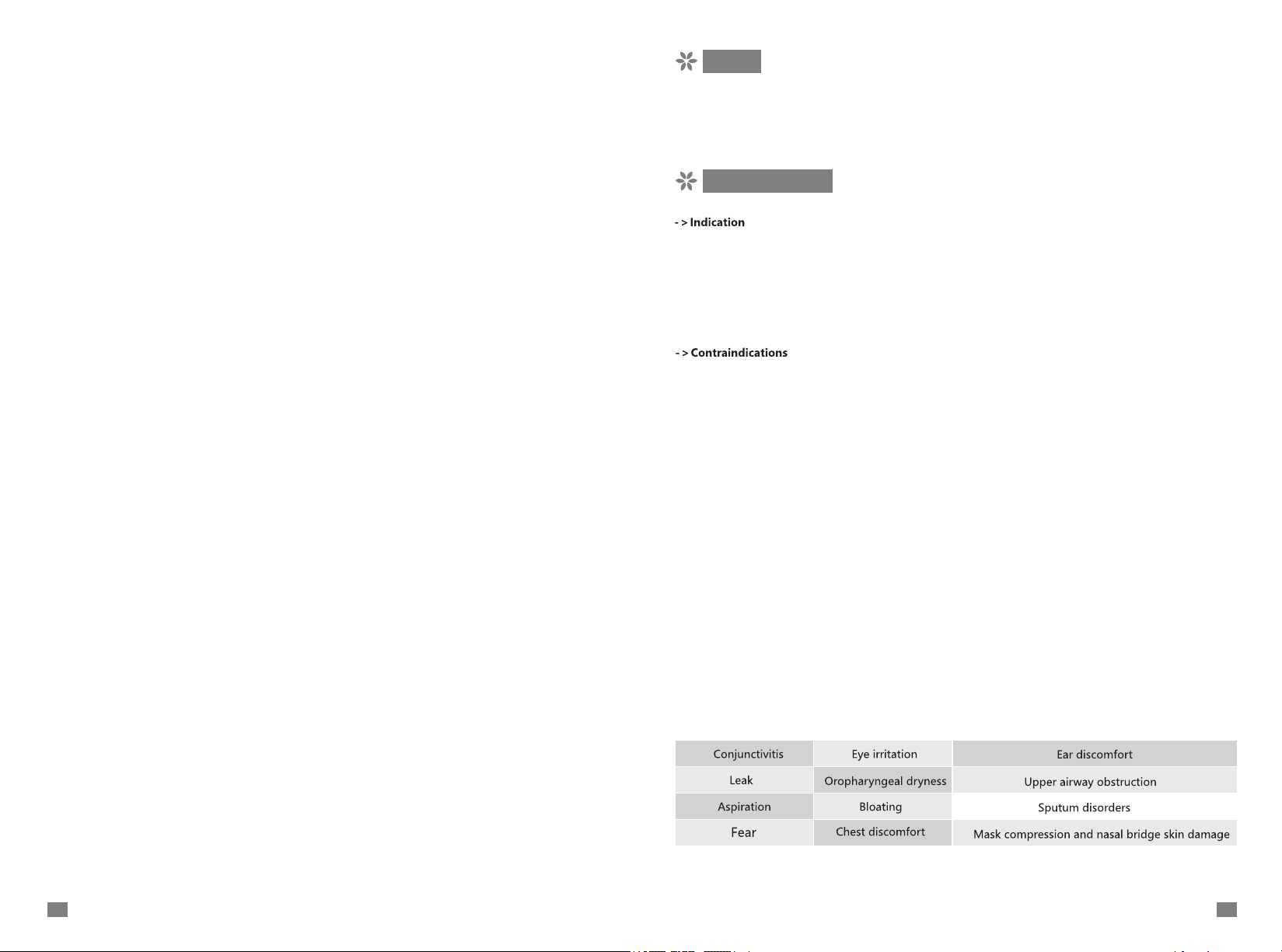
->Adverse reactions
If the patient has abnormal chest pain, dyspnea or severe headache or other adverse reactions,please
contact the clinician immediately.
During the use of the ventilator, the following adverse reactions may occur:
0403
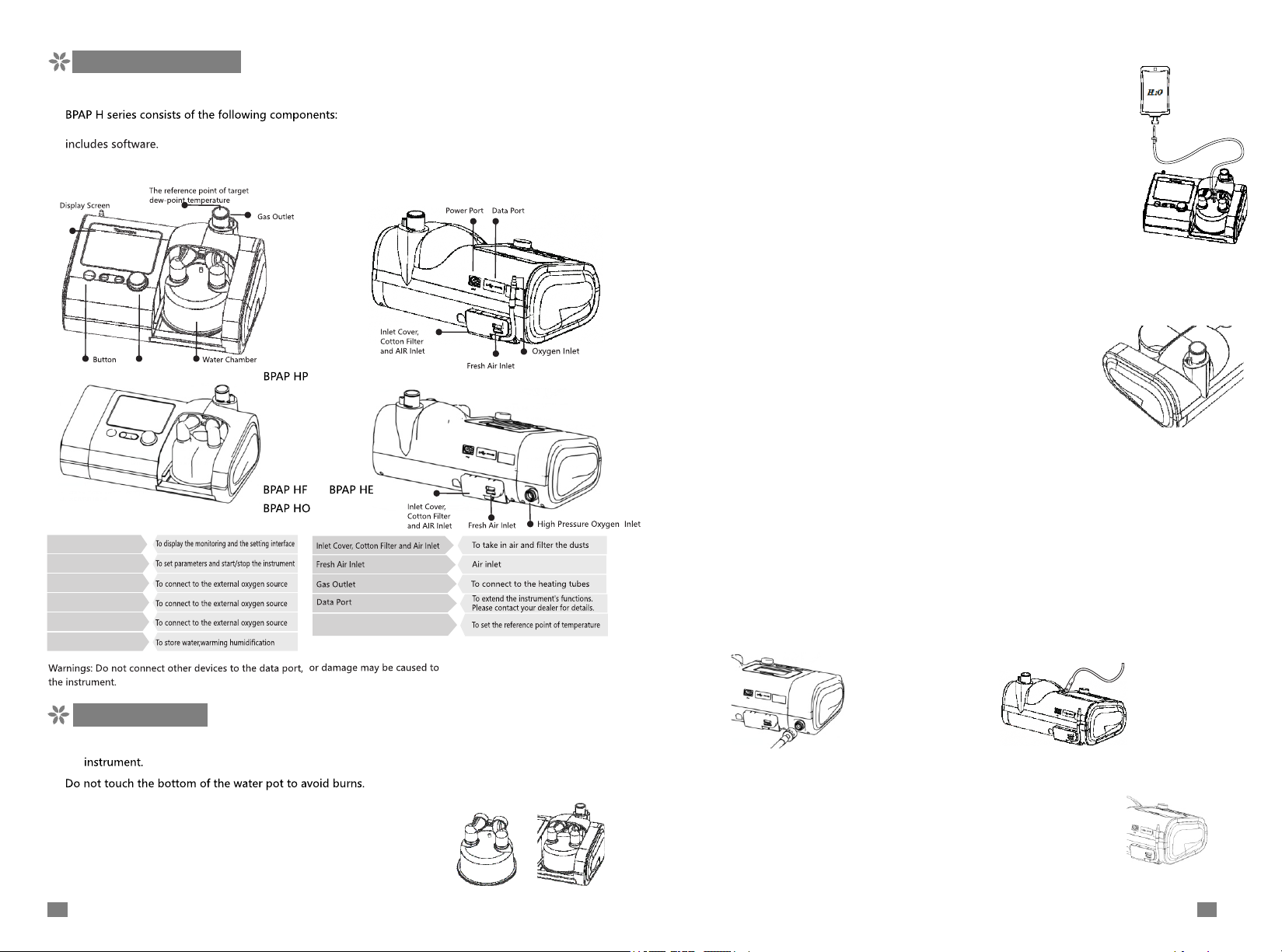
Instrument Information
->Instrument Components
Instrument.Water chamber.Heated breathing tube.mask or nasal cannula. The instrument
->Components and Functions
/
BPAP H
/
Display screen
Buttons
High Pressure Oxygen Inlet
Oxygen Inlet
Power Port
Water Chamber
Water Chamber - for dew poit and
reference point of temperature
->Connect the water bag
Hang sterile water bag onto the instrument's high position whenuse the Water
chamber, insert the inlet needle into the rubber plug of water bag, and open the
bag's vents. The Water chamber will be added with water automaticallyaccording
to a fixed level.
->Warnings:
Please use a medical treatment and no more than 2000ml of sterilized water.
After connecting into the water bag, check whether the water is flowing into the
Water chamberand kept below the water line. In case of any problem, replace
the Water chamber.
Make sure water in the Water chamber and water bag will not run out during
use. Otherwise it will cause the Water chamber to run dry and affect the
humidification effect.
When the Water chamber run dry,please replace Water chamber to avoid
Water chamberdamage.
->Connect the heating tubes
In Ventilation mode: Connect the mask, Heated breathing tube
and gas outlet of the ventilator.
In High Flow mode: Connect the nasal cannula, Water chamber
and Heated breathing tube to the gas outlet of the ventilator.
->Warnings:
Please check the Heated breathing tube before connection. If it is damaged or bent, please replace the Heated
breathing tube.The human body should not be in contact with the Heated breathing tube for a long time,
otherwise it may cause danger or personal injury.
The Heated breathing tube should not be close to any heating body, and should not cover anything,
otherwise it may cause danger or personal injury.
The Heated breathing tube should be kept away from all kinds of objects with electronic radiation, as
well as
various wires and wires to prevent interference.
->Connect to the oxygen source
Ventilator can be connected to external oxygen to max flow 80L/min, but not to over current flow.
Connect the outlet of oxygen source tothe inlet port of device, ensure the proper assembly.
System Assembly
! Warnings: when the Water chamber and Heated breathing tube are not installed well, do not open
the
->Fill Water chamber
★ Depress the hand guard to insert the Water chamber into the instrument,
making it closely connected tothe instrument's interfaces, and then, the
hand guardis rebounded back into place.
05
BPAP HF/BPAP HE/BPAP HO BPAP HP/BPAP H
->Connect to the power
Connect the power adapter to the power port on the back of the
instrument and then, insert the AC connector into the AC socket.
The instrument's screen lights up, which means it is powered properly.
06

Operation Panel
->Buttons
->LCD Display Screen
★
The LCD display screen can display the monitoring interface and the setting interface.
★
The High Flow mode monitoring interface: display the operating mode, monitor oxygen
concentration, flow
● Press this button to enter or exit the mute status.
● In standby mode, long press to enter the transit mode for 20 minutes
or exit the transit mode.
● The shuttle has three basic operations: confirm(Press down), turn left, turn right.
● The shuttle confirm button: In the setting status, press down this button to selector exit
the current function.
● Turn left/right: To realize switching options in the setting mode. To increase ordecrease
data under data-modifying status in the setting mode.
and temperature.
Mode->S/T
Mode
Tube off
RATE VT
★
Ventilation mode monitoring interface: display working mode, monitoringparameters,
setting parameters, alarm information, SD card status, etc.
When the monitoring interface waveform color is white, it is in standby state, green is
autonomous triggering state, and red is timing triggering state.
07
Setting parameters
->Operation method
In the monitoring status, Press this button to enter the setting status.
In the setting interface, when the interface is switched, turn left the
shuttle to exit.
When the mode, alarm, system configuration interface is switched, press
the shuttleto enter the current interface option switching state.
In the setting interface, when the interface is switched, turn left the
shuttle to the exit. When the option is switched to the current interface
icon on the left,press the shuttle to enter the interface switching state
again.
After entering a setting interface, turn left or right the shuttle to switch
between various parameter options on this interface.
08

Press th e sh uttle c onfir mation key to e nt er the st at e of par ameter
modi fi catio n af ter swi tc hing to a para meter item, a nd t hen the
anti -d ispla y d ialog box of th e s el ected para me ter item will ligh ten.
Press th e shu tt le key to m odify the pa rameter, and then p re ss the
shu t t l e k e y t o re t u r n t o t h e s t a t e o f o p t i on s wit c h i n g
Note: whe n the para meter bit is in gray state , thi s f unction is no t
availa bl e in the cu rrent sta te ; when se tting c linical p ar amete rs such
as mode, the cli nical sett ing ite m in the system config urati on is
clos ed ( see the ico n in t he uppe r ri ght cor ner of t he m ode set ting
wind ow ), and the cli ni cal par amete rs such as m od e c annot be
chan ge d
MVAPS
Tidal volume
control
Lflow mode
(BPAP HF/BPAP HE)
Hflow mode
(BPAP HF/BPAP HE)
mode
Tidal volume :200~2000ml ;
IPAP Max:
IPAP Min:
EPAP:0.4~2.0 kPa;
Insp. Time:0.5-3s
Ramp
FiO2:21~100%(BPAP HF / BPAP HE / BPAP HO)
0.4~4.0kPa(BPAP
0.4~4.0kPa(BPAP
time:0~3min
Flow:2~25L/Min ;
FiO2:21~100%
Flow:10~80L/Min;
FiO2:21~100%
HF)
0.4~3.0kPa (BPAP HE / BPAP HO / BPAP H)
HF)
0.4~3.0kPa (BPAP HE / BPAP HO / BPAPH)
Risingtime :
I-trigger:
1~6,
Temperature :
Temperature:34℃.
;
Temperature:29-37℃.
;
0.1~0.6s,
auto
E-trigger: 1~6, auto
auto
℃
29~34
Frequency:2-40Bpm
;
off
;
;
;
Return to menu
->Operation mode
Modes
CPAP
S
Spontaneous mode
T
Timing
Timing
S/T
Spontaneous/timing mode
control
mode
When t he interface c hange s st ate, pres s the lef t key of shuttl e to
the ex it i con to retu rn to the mon itoring i nterf ace. At thi s time, t he
chan ge s made to par ameters a re a utoma tically s tored.
Parameter setting
:
29~34
auto
;
Ramp time :0~60min
;
Temperature:
HF / BPAP
HE / BPAP HO / BPAP H)
Rising time
Ramp
;
off
℃
Rising time:
E-trigger:1~6,auto
Insp. Time:0.5-3s
0.1~0.6s
:
time 0~3min
:
0.1~0.6s
HE / BPAP
29~34
HE / BPAP
;
;
;
auto
Temperature
HO)
;
℃;
off
HO) ;
auto
I-trigger :
Frequency : 2-40Bpm
:
;
29~34
1~6,
auto
℃
off ;
CPAP:0.4~2.0kPa
C-Flex :1~3 off
FiO2:21~100%(BPAP
IPAP:0.4~4.0kPa(BPAP HF)
0.4~3.0kPa(BPAP
EPAP:0.4~2.0 kPa;
:
E-trigger 1~6,auto
temperature
FiO2:21~100%(BPAP HF/BPAP HE/BPAP HO)
IPAP : 0.4~4.0kPa(BPAP HF)
0.4~3.0kPa(BPAP HE / BPAP HO / BPAP H) ;
EPAP:0.4~2.0 kPa;Risingtime 0.1~0.6s auto Frequency:2-40Bpm
Ramp: tine 0~3min lnsp.time : 0.5~3s Temperature : 29~34 ℃ off;
FiO2:21~100%(BPAP HF / BPAP HE / BPAP HO) ;
IPAP:0.4~4.0kPa(BPAP HF)
0.4~3.0kPa(BPAP HE/BPAP HO/BPAP H)
EPAP:0.4~2.0 kPa;
I-trigger:
Ramp
FiO2:21~100%(BPAP HF / BPAP
1~6,
time: 0~3min
Note: in br ea thing mode , the insp irato r y and respir atory tr ansit ions are tri ggered by ti me or by
the pati ent. Acco rd ing to th e pa tient's respi ra tor y vel oc ity and p re ssure, th e inspi rator y tri ggeri ng
sens it ivity and e xpira tor y switc hi ng sens itivi ty were set at 1~6 levels. The sensit ivity gra duall y
decrea sed, whic h wa s re la ted to t he t reatmen t of dis eases and the c omfor t level of patien ts , and
must b e a djusted by profess ional d octor s acc ording to th e s pe cific tre atmen t con ditio ns of
indi vi duals
->Alarm
The no n- invasiv e ve ntila to r is equi pped wi th visu al a larm si gnal an d so und ala rm sign al. When
the alarm is ge nerated du ri ng use, the op er ator is directl y i n f ro nt of the ven tilator, facing th e
LCD di splay sc re en, and the vi sual ala rm si gnal can be cl early ob ser ved . At thi s t ime, it sho uld
be han dl ed as soo n as poss ible acco rd ing to th e ac tual si tuati on to avoid r is ks.
The visual alarm signal is shown in the right figure.
represents alarm
means sound alarm paused
The alarm type is described in text beside the icon
,
.
.
PC
Pressure
control mode
IPAP:0.4~4.0kPa(BPAP HF)
0.4~3.0kPa(BPAP HE / BPAP
EPAP :0.4~2.0 kPa;
I-trigger:
1~6, auto
Ramp
time: 0~3min
FiO2:21~100%(BPAP
Rising time:
Insp. Time:0.5-3s
HF / BPAP
HO / BPAP
0.1~0.6s
Temperature
HE / BPAP HO)
;
H)
auto
Frequency : 2-40Bpm.
29~34
:
;
.
;
off
℃

Internal fault
Af te r starting up, when the
moto r and othe r i ntern al
comp on ents ha ve faul ts , the
-
faul t a la rm and soun d a larm
shall b e displa yed within
5 seco nd s.
Res tar t aft er shutdo wn .
If a l a r m s t i l l exi s t s ,
cont ac t your supp lier
or RMS
Middle
High re spirato r y
freque ncy ala rm
S/T、S、T、PC、M VAP SIn the
off:
1~19 bp m
Preset : of f
mode s of S/T, S , T,P C and
MVAPS , if t he patien t's
respir atory rate i s de tected to
be hig he r than th e set
thresh old, the hi gh respir atory
rate ala rm will b e pr ompted.
1Check the patient's
ventilation status
2.Check whether the
alarm threshold of high
respiratory rate is too
small
3. Press the mute button
Middle
Overtemperature
alarm
High in spira tor y
pressu re a larm
S/T、 S、 CPAP、 PC、 MVAPS
When oper ation in modes of
S/T, S, CPAP, PC, M VAPS,
ob vio u s l eak age det ect ed
duri ng e quipm ent ope ratio n
will prompt the pip e to fall
off and alar m.
S/T、 S、 CPAP、 PC、 MVA PS
at S /T, S, C PAP, PC, MVAPS
mode s, i f no breath ingac tion
is detected wi th in the set
alar m tim e, the s uffoc ation
alar m wi ll be promp ted
When t he v entil ator dete ct s
that t he t emper ature at the
conn ec tion po r t of the p at ient
(breat hing mode i s the end of
the resp iratory pi pelin e, while
humi di ficat ion mod e is the
endof the na sal plu g cathe te r)
exceed s 43℃, an
over tempe rature al arm and a n
audi bl e alarm s hall be
disp la yed wit hin 15 se co nds.
S/T、S、T、CPAP、PC、MVAP S
at S/T, S, CPAP, PC, MVAP S
mo des , t h e p res sur e a tth e
j u nc ti o n o f t he p a t ie n t
(breat hing m ode is the en d
of the tub e) is 3 kPa h igher,
w h i ch s h ou l d s h o w h i g h
i n s pi ra t or y p r es s ur e a n d
gene ra te soun d alarm.
Chec k wh ether t he tube
and ma sk i s conne cted
correc tly
Press th e mute button
1.Ch ec k the patie nt's
ventil ation s tatus
2. Che ck w hethe r thepi pe
mask i s co nnect ed
correc tly
3. Che ck w hethe r the
thresh old time of the
suff oc ation a larm is too
smal l
4. Press t he mute but to n.
1.Ch ec k the ven tilator
for ma lf uncti on
2. Che ck w hethe r theus e
envi ro nment m ee ts the
requirem ents
3. Che ck w hethe r the
breath ing line is
dama ge d
4. Ple as e conta ct the
supp li er or RMS
1.Ch ec k wheth er the
tube is b locked
2.Ch ec k wheth er the
ventil ator is out ofo rd er
3.Ch ec k the patie nt's
respir atory stat us
4.Pl ea se cont act the
supp li er or RMS
Middle
Middle
Middle
Middle
Low respiratory
frequency alarm
Leakage alarm
Obstruction
alarm
S/T、S、T、PC、M VAP SIn the
mode s of S/T, S , T,P C and
MVAPS , if t he patien t's
respir atory rate i s de tected to
be lower t han the s et thresh ol d,
the lo w re spirato r y rate alar m
will b e pr ompted.
S/T、S、T、P C、M VAP SIn S /T, S,
T, PC and MVAP S mod es, i f t he
de t e c ted m i n ute v entila t i o n
volume is lower than th e set
thresh old, t he l ow v entilat ion
volume a larm wi ll be promp te d.
In l ow flow mode and high fl ow
mode , if t he vent ilator do es not
detect the he ated breathi ng
-
tu b e af t e r s t a r t ing u p, t h e
br e a th i n g tu b e a l ar m a n d
soun d al arm shall b e di splay ed
with in 5 s econd s.
In low flow mod e a nd high flo w
mode , if the ven tilator det ects
abno rm al air leak age in the
-
system , it shal l displa y the air
leak ag e alarm a nd gene rate the
soun d al arm wit hin 5 sec on ds.
In low flow mod e a nd high flow
mode , if the ven ti lator detec ts
that the system is blo cked, i t
-
shal l di splay t he bloc king alar m
and generate the sou nd alar m
with in 1 0 secon ds.
1Check the patient's
ventilation status
2.Check whether the
alarm threshold of low
respiratory rate is too
large
3. Press the mute button
1.Check the patient's
ventilation status
2.Check whether thealarm
threshold ofminute
ventilationvolume is too
low
3.Check whether thetube&
mask is connectedcorrectly
4. Press the mute button
Conf ir m that the Heated
br e athin g t ube i s n o t
da mage d a n d i nse r t ed
correc tly. If the al arm still
exi s t s , p l e a s e r e p l a ce
the H e a t e d breathi n g
tube
1.Ch ec k wheth er the wa te r
cham be r is inst alled i nplac e
2. Che ck w hethe r the
breath ing circu it i s
dama ge d and ins ert ed
correc tly
1. C he ck for ob struc ti on
of water tan k, respir atory
tube o r na sal can nula
2.Ch ec k wheth er the in let
hood a nd f ilter c ot ton are
bloc ked
Middle
Middle
Middle
Middle
Middle

When the measu red oxy gen
conc en trati on is lowe r tha n the
limi t val ue, t he lo w oxy gen
conc en trati on alar m and sound
alar m shal l be di splayed withi n
20 sec on ds
When th e mea sured oxygen
concen t r a t i o n e x c e e d s t h e
li m it val u e, a h i gh oxyg e n
co n c e ntrat i o n a l a rm a n d a
soun d al arm sha ll be dis played
with in 2 0 secon ds
In low f lo w mode an d high fl ow
mode , whe n the ventil ator fails
to re ach th e set flow rate in 1 0
minu te s (±1 m inute), it s ho uld
disp la y th e fa ilure to rea ch t he
-
ta rge t f l ow rate a l arm and
gene ra te soun d alarm.
Chec k wh ether t he oxygen
s o u r c e i s p r o p e r l y
conn ec ted to the oxygen
inle t of t h e v e n t i l a tor
Ad jus t t h e f low of t he
oxygen s ou rce as need ed
1. Adj us t the flo w of oxy gen
source a s neede d
2. Che ck t he oxygen s ource
Chec k fo r obstr uctio n of
water ch amber t ube or
nasa l ca nnula
Chec k wh ether t he inle t
hood a nd f ilter c ot ton are
bloc ked
Chec k wh ether t he sett ing
flow i s to o highRepla ce the
large na sal cannu la
Middle
Middle
Middle
1.Wh en t he room
In low f lo w mode an d high fl ow
mode , when starti ng up , when
t h e p i pe li ne t e m p er at ur e
Chec k th e
servi ce
situ at ion
Af te r the ala rm limit is s et and stor ed n ormal ly, it wil l still b e stored in the d evice a fter po we r
fail ur e
When the noninvasive ventilator is used for the first time, monthly or after storage, it shall checkwhether
the alarm system functions normally according to the alarm description
For example, in humidification mode, remove the Heated breathing tube, and you should beable to see
the "breathing tube" alarm signal and hear the sound alarm. If neither occurs, pleasedo not continue to
use the ventilator, and please contact the supplier or RMS
exceed s the r ange of 10~3 0℃ ,
60 seconds (±6 s econd s) sha ll
d i s p l a y t h e w o r k i n g
e n v i r o n m e n t a l a r m a n d
gene ra te the so und alarm .
In the s ta r tup sta te , the exter nal
power is disc onnec te d and the
s o u nd a la rm i s g e ne r a t ed
with in 10 seconds , lastin g for
more tha n 120 secon ds.
temper ature exc ee ds the
rang e of 10~ 30℃, plea se
do not u se t he low fl ow
mode o r hi gh flow m ode
of the venti lator, which
may no t re ach the set
temper ature
2.Wh en t he use
envi ro nment s ud denly
chan ge s, may ca use ala rm,
plea se s tar t aga in a t room
temper ature for 3 0 minutes
1 Chec k if p ower is
conn ec ted prope rly
2 Chec k wh ether t he
networ k power s upply is
norm al
Middle
Middle
W h e n t h e w a t e r i n t h e
humi di fyi ng tank i s used up , th e
chec k water volu me alarm and
soun d a larm s ha ll be d is playe d
with in 20 min utes (fl ow rat e
-
high er than 2 0 l /min) or withi n
40 m inu tes ( flo w rat e l ower
than 2 0 l/ min)
In low f lo w mode an d h igh fl ow
mode , wh en the ve nt ilato r fa ils
to re ach the set tem perat ur e
with in 3 0 minut es (±3 minu tes),
-
it shall d ispla y the failu re t o
reach the tem pe rature alarm
and ge ne rate th e sound ala rm.
Chec k wh ether t he water
in the c hamber is b oiled
up, which may damag e
t h e c ha mb e r. P le as e
ensu re that the wate r i n
the c hambe r will not be
used u p
Ventila tor fl ow is too
high , and the ambien t
temper ature is too lo w,
reduce the target flow
or targe t te mpera ture
When t he b reathin g mode an d the hum id ifica tion mo de switch e ac h other, the " check patie nt
interface" i s prompte d to rem ind the c orrect us e of the m ask or na sal can nu lathe m ode swi tc h
Middle
Middle

start using
->Device connection
->Parameter setup
.
->Notice
In High Flow mode, when the trigger fails to reach the target flow alarm, it may be that the model
of the nasal cannula is not suitable and the large-size nasal cannula needs to be replaced. It is
recommended that the flow of the NAC-1S nasal cannula should be less than 50L/min, and that of
the NAC-1M nasal cannula should be less than 60L/min.
When Ventilation mode and High Flow mode exchanges each other, the "exchange of patient
interface" is prompted to remind the correct use of the mask or nasal cannula after the mode
exchange
->Start to operation
Press the start/stop button for 3 seconds to start the ventilator
Note: when using the humidification mode, the ventilator starts to
preheat first, then the flow rate and dew point temperature will
fluctuate and rise. After reaching the preset value, the value will
remain unchanged. After preheating working word appears.
->Oxygen adjustment
.
.
.
.
.
.
Chec k th e wo rk ing mode. Wear the mask in the respir atory mode acc or ding to th e
requirem ents of the m as k instr uctio ns. We ar the na sal cannu la in the h umidi ficatio n
mode a cc ording to t he requirem ents of the nas al cann ula ins tr uctio ns.
->Notice
In case of po wer fail ure or mach ine fa il ure, ple ase remo ve the mask to avoid repe ated
★
inha la tion of you r exhalat ion.
★
The ou tl et of the dev ice sho uld alway s be lowe r th an the he ight of the pat ient tube a nd
the ma sk /nasa l cannu la to prevent w ater from ent er ing the t ube.
★
In the monitorin g inte rfa ce, when ala rm is gene rated by the dev ic e, p re ss the mute
button to t em porar ily tu rn off the sound . If the alarm still exist s, t he ala rm w ill so und
agai n tw o minut es l ater.
Duri ng the tre at ment, the mac hine w ill gener ate an ala rm w hen the externa l powe r
★
supp ly is in terru pt ed (press the st ar t /stop button to tu rn off the so und). Th e use r
shou ld tur n off t he oxyge n source , remo ve the mask o r na sal pl ug cat heter and ch eck
the p ower sup ply. Af ter th e exte rn al p ow er is r es tored, p re ss the start/ st op but to n on
the pane l to c ontin ue usin g.
->Transport function (High Flow mode)
When u si ng the Hi gh Flow m ode, pres s th e mute bu tton for 3 se conds in th e stand by,
prehea t or ready state to st art th e ven tilator to e nter the t ransf er fu nctio n. ve ntila to r
works in low c onsum ption , no Heate d brea thing tub e and wate r c ha mber; After 20
minu te s, ente r the prehe ating s ta te, and t he tube a nd water ch amber s tar t heati ng.
->End of operation
At the e nd of use, f irst rem ove the m ask or na sal pl ug cathe ter, t urn off the ox ygen
source , pull o ut the oxyge n tube, and press the sta rt/ stop b utton for 3 seconds .
The d evice enter s th e dr y mode, dry t he p ipeli ne, an d th e dr y mode will run for 99
minu te s
.
.
.
Make sure the ventilator is switched on when oxygen is used.
★
Oxygen can only be delivered through the ventilator's own oxygen inlet.
★
Ensure proper installation of oxygen tube, air inlet hood and filter cotton, and secureinstallation
★
of power connection.
After use, be sure to turn off the oxygen source first, unplug the oxygen tube, wait forthe
★
ventilator oxygen concentration has been completely reduced to air oxygenconcentration before
turning off the ventilator.
★
Make sure to turn off the oxygen when the ventilator is not working to prevent theaccumulation
of oxygen in the ventilator.
★
S
pecial attention should be paid to reducing the fire risk when using oxygen therapy.It should be
used away from the source of the fire.
★
T he ventilator should be kept in a well-ventilated place.
F
or safety reasons, all igniters should be kept away from the ventilator, preferably not in the same
★
room as the ventilator. The sign forbidding fireworks should be conspicuous.
★
A
void creating sparks near medical oxygen equipment, including electrostatic sparks fromfriction.
t must be kept away from oil, grease or oily substances, which are prone to spontaneous
I
★
combustion when exposed to oxygen under pressure.
If you wan t to force dr y m od e of f, press the s tar t/stop bu tton for an other 3 s econds,
but th e st ored wet ga s in t he tube m ay affe ct the next o perat ion.
->Warning
★ After usage, be sure to turn off the oxygen to avoid the accumulation of oxygen in the ventilator.
★ In the drying process, do not wear a nasal cannula, so as not to cause damage to the body.
Cleaning and maintenance
Noni nv as ive ve ntila to rs use w ater humidi ficat io n, such as irreg ular cleani ng,
disi nf ectio n and repla cemen t of par ts, w hich ma y carry a ri sk of ba ct erial g ro wth
and in fe ction i n the patie nt
The n oninvas ive vent ilator must be cle aned a fte r firs t use, aft er eac h use, or a fter
storag e for nex t op erati on.
Noni nv as ive ven ti lator s must be c le aned an d disin fected be tween pat ie nts or af ter
two week s of u se.
->cleaning
Dail y cleani ng: He ated b re athing t ube, n asal c annul a, ful l face /n asal m ask Af ter us e,
remove the nasal can nula and cle an it w ith clean water, then conne ct the Heated
breath ing t ube, run the d r ying mod e, an d d r y t he Heated breat hing tub eand nasal
cann ul a.
Full f ac e/nas al mask : clean in g as per at tache d instruc tion.
Wee kly clean ing: n oninvas ive ve ntila to r, nasal cann ula, r espirat ory l ine, f ilter cotto n
Disc on nect th e venti la tor, re move the na sal can nula, and w ash the c annul a wi th warm
water an d neutr al detergen t.

Use a cl ea n, non- fuzz di sposabl e wet clo th dipped i n neutr al detergen t from both e nds of the
elbo w to e nsure tha t all dir t is remo ved.
Wipe e lb ows and a djace nt areas wi th a lcoho l cotton to e nsure tha t al l dir t is remo ve d.Breat hing
tube : cl ean the a ir line w ith mil d de tergent i n warm wate r. Rins e thoroug hly and
hang d r y.
Filter c otton cle aning : filter co tton is pla ced in th e intake hood o n the sid e of t he v entil ator,
whic h ca n be taken ou t directl y. Wash wit h neutr al w ashin g fluid . After w ashin g, p ut it in th e
shad e to d r y.
Filter c otton sho uld be repl aced af ter 1 mon th of use.
In order to en sure the lo ng-term u se of the venti lator, the use r must fo ll ow the ve ntila to r
safe ty a nd clea ning in struc ti ons.
When t he v entil ator is out of us e, do not thr ow i t away, pl ease co ntact R MS o r suppl ier.
The li fe o f th e venti lator is 10 y ea rs.
The da te of prod uctio n of t he v entil ator is sho wn on the l ab el.
War ra nty spe cific ation : se e warra nty card.
Troubleshooting
★
★
Do not u se a ceton e, chlori des or fros te d clean ers.
Do not u se a s oluti on above 50 ℃.
Plea se d o not load th e wet fil te r cotton on to the equi pment , other w ise it will d amage t he
equi pm ent.F ilter c ot ton is us ed t o filter du st, but i f it is not cle aned an d re place d in time ,
it wil l af fect
your hea lth or ca use equ ip ment fa ilure due t o bl ocked air i ntake. Ther e is a w arnin g sticker
with th e w ords "filt er cotton is c le aned a nd re place d reg ularl y" at the ai r i ntake to remind
you.If the externa l dust, s moke is l arger, t he tim e to repl ace the filt er cotto n shou ld be
shor ten ed a ccordin g to the spec ific si tuati on .
->Di sinfect ing
Cut off t he v en ti la to r,
pull out the chamber,
and clean the
ventilato r.
Connect the ozonator
interface to the nasal
cannula side of t he
res pi ra to r y tu be .
Insert t he g as r es is to r
as shown.
Pre ss t he o zo na to r
butto n to s ta r t
disinfection. Af te r
about 35 minutes,
the ozonato r wi ll
be shut down and
let stand for 1 hour
to co mp le te
disinfection.
Rem ov e th e resistore
and ozonato r, in st al l
the chamber, tur n on
the power supply,
dr y th e tu be , cu t of f
the power supply
af ter dr ying.
-Filter foam or outlet blockage
-The Heated breathing tube is
damaged and leaks air
-water chamber installation is not
in place or damaged
-The Heated breathing tube
connected improperly
-Incompatible tube is used
-The H ea ted brea thing tu be is not
conn ec ted or im properl y co nnect ed
-lea ka ge in nas al cann ula or
Heated breathi ng tub e
-Equ ip ment mo tor failu re o r
conn ec tion prob lem
-The d ev ice fal ls into the w ater, or
the wa te r enter s th e devic e
-Clean or replace the filter,
clean the outlet
-Replace nasal cannula or
Heated breathing tube
-Check that the connection
is correct and reliable
-Use only the equipment
recommended and provided
by RMS
-contact with RMS or supplier
-Che ck w hethe r the dev ice is
conn ec ted to the po wer sup pl y
correc tly
-con ta ct with R MS or sup pl ier
-Rai se t he humi dif ying
-tempe rature, o r consu lt y our
doctor
★
★
★
Heated breathing tube make sure that the instrument is powered off.
Heated breathing tube is unblocked.
★
->Replacement of parts
Service and Repair
When t he w arran ty servi ce is requi re d, if nec es sar y, t he product ci rc uit dia gram an d re pa irabl e
comp on ent inf ormat ion can be pr ov ided to t he q ualif ied techn ician s ident ified by us .
-Cle an o r replace f ilter c ot ton
and cl ea n vent
-Cha ng e mask or H eated
breath ing tube
-Ple as e Wate r chambe r
-Che ck t hat the c onnec tion is
correc t and relia bl e
-Use o nl y the equ ipmen t
recomm ended and p ro vided
by RMS
-Wa it f or the pres sure to ris e or
canc el , shorten th e pressure
ramp t im e

->Ventilation mode
Pai n in the no se
or ear s
Device technical indicators
->High flow mode
-The Heated breathing tube is not
connected or improperly connected
-Mask or Heated breathing tube
leakage
-The water chamber is not well
connected to the main device
-Inflammation
-Check if the Heated breathing
tube is connected properly
-Check the Heated breathing
tube for leaks
-Check whether the water
chamber is connected to the
main machine properly
-Consult a doctor
Humi di ty Outp ut
100-2500ml BTPS, ±20% RS/±100ml
1-30L BTPS,±20% RS/± 1L
<30dB(A) (CPAP,1.0 kPa)
≥12mg/L
175 SLPM
≥90mL(HC-B1)
Maxi mu m oxygen in put
Humi di ty Outp ut
Maxi mu m tempe rature
of deliver y ed gas
2~80 L /m in;
Lflo w mo de:2~25 L /min,34℃ ;
Hflo w mo de:10~8 0L/mi n,29℃~37℃
>33m g/ L( 2~80 L/min、3 7°C ) (Avail able fo r pa tient s with uppe r
respir atory trac t bypasse d)>12mg /L( 2~8 0L/mi n、29°C ~36°C )
10 min ut es to 31℃ , 30 min utes to 37℃
(water c hambe r( HC-B1 ),fl ow35L /min in it ial tem peratur e 23±2℃)
10L/ mi n,<20 dB(A) (Hfl ow mode)
>45dB(A)(1m distance)
230V~, 50Hz
350VA
29.1x18.6x16.2cm
2.0Kg(BPAP H/BPAP HP); 2.5Kg(BPAP HF/ BPAP HE/ BPAP HO)
Classification of equipment : II BF Grade of waterproof : IP21
Running mode : continuous operationIn the case of Flammable
anesthetic gas mixed with air or with oxygen or nitrous oxide,
the device do not use .
Air pressure 70~106kPa
Operating temperature in high flow mode 18℃~28℃
Operating temperature in respiratory mode 5℃~35℃
service temperature 10~95%、 No condensation
Storage temperature -20~60℃
Storage humidity 10~95%、 No condensation

Air Circuit Diagram
User
Fresh air / medical oxygen
Inlet filtration
Instrument
Appendix A: Electromagnetic Compatibility
Fan
Guidelines and manufacturer's declaration - electromagnetic emissions:
The Noninvasive ventilator is intended for use in the electromagnetic environment s pecified as below and
the purchasers and users should ensure that it is used in such an electromagnetic environment.
Nasal cannulas
Heated
breathing
tube
Electric Circuit Diagram
230L
Turn on/off
power supply
230N
Packing list
(AIRT-B4)Heated Breathing Circuits (optional)
Water chamber
operation panel
(display and buttons)
Main control
panel
Fan
Oxygen
concentration
detection
Flow and oxygen
concentration detection
The Noninvasive ventilator uses RF energy only for its internal
function. Therefore, it has a very low RF emission, and has a very
small possibility of interference with nearby electronic equipment.
The Noninvasive ventilator is suitable for use in all facilities,
including residential facilities and direct connection to public
low-voltage power supply network for residential buildings.
Guidelines and manufacturer's declaration - electromagnetic immunity:
The Noninvasive ventilator is intended for use in the electromagnetic environment specified as below and
purchasers and users should ensure that it is used in such an electromagnetic environment.
the
Networks power supply should be qualified
for being used in typical commercial or
hospital environment. If the user needs
continuous operation of the Noninvasive
ventilatorduring
power interruption, it is recommended to
utilize an uninterruptible power supply or
batteries.
User manual
Guidelines and manufacturer's declaration - electromagnetic immunity:
The Noninvasive ventilator is intended for use in the electromagneticenvironment specified as below and
the purchasers and users should ensure that it is used in suchan electromagnetic environment.

->Where
P — the max rated output power of transmitter, provided by the manufacturer, unit: W;
d — the recommended separation distance, unit: m;
The field strength of Fixed RF transmitters is to be determined by measurement “a” of the electromagnetic field
and for each frequency range, should be lower than the coincident detection level.
Note 1: at the 80MHz and 800MHz frequencies, formula of the higher frequency band will be used.
Note 2: these guidelines may not apply in all cases. Electromagnetic propagation will be affected by absorption
and reflection of buildings, objects, and human bodies.
a. For fixed transmitters, such as: the base stations of wireless (cellular / cordless) telephones and ground mobile
radio, the amateur radio, the AM and FM radio broadcast and TV broadcast, the field strength cannot be
accurately predicted in theory. To assess electromagnetic environment of fixed RF transmitters, measurement
of electromagnetic field should be considered. If the measured field strength of Noninvasive ventilator is higher
than the above applicable RF coincident Detection level, observation should be conducted to the Noninvasive
ventilator to verify its normal operation. If normal performance cannot be observed, additional measures may
be necessary, for example, re-adjusting the direction or location of the respiratory humidification therapeutic
instrument.
b. Within the entire frequency range of 150 kHz ~ 80MHz, field strengths should be less than 3V/m.
Recommended separation distance between the portable and mobile RF communication equipment and the
Noninvasive ventilator:
The Noninvasive ventilator is intended for use in an electromagnetic environment with a controlled radio
frequency radiation disturbance. According to the maximum rated output power of communication equipment,
the purchaser or the user can prevent electromagnetic interference by adopting the following recommended
minimum distance between the portable and mobile RF (transmitters) communication devices and the
Noninvasive ventilator.
For maximum rated output power of transmitters not listed in the above table, the recommended separation
distance d, in meters (m), can be determined by use of the formula in corresponding transmitter frequency
column, where P is the max rated output power in watts (w) of transmitter, provided by the manufacturer.
Note 1: at the 80MHz and 800MHz frequencies, formula of the higher frequency band will be used.
Note 2: these guidelines may not apply in all cases. Electromagnetic propagation will be affected
by absorption and reflection of buildings, objects, and human bodies.
 Loading...