

Page 1

.LQGHUNDPDFN5G3DUN5LGJH1-
Phone • Toll-Free 1-800--
www.DPJDLU.com • LQIR@DPJDLU.com
HI-E DRY 195 Installation, Operation & Service Instructions
Table of Contents
1. Specifications ........................................................1
2. Installation ............................................................1
2.1 Location .........................................................1
2.1A In humid area, no ducting. .........................1
2.1B In humid area, duct inlet and/or outlet. ......1
2.1C In remote area, duct inlet & outlet. ............2
2.1D In remote area, duct outlet only. ................2
2.1E In remote area, duct inlet only. ..................2
2.2 Electrical Requirements ...................................2
2.3 Condensate Removal ......................................2
2.4 Ducting ..........................................................2
2.4A Optional Ducting kit ..................................2
2.4B Ducting for Dehumidification .....................2
2.4C Ducting for Fresh Air .................................2
2.5 Optional Remote Humidity Control ....................3
2.6 Hard Wiring The HI-E Dry 195 ...........................3
3. Operation .............................................................4
3.1 Humidity Control Adjustment ............................4
3.2 Fan Switch ......................................................4
3.3 Defrost Control Adjustment ..............................4
3.4 Low Pressure Control .......................................4
4. Maintenance .........................................................5
4.1 Air Filter ..........................................................5
5. Service .................................................................5
5.1 Warranty.........................................................5
5.2 Technical description .......................................5
5.3 Troubleshooting ...............................................5
5.4 Refrigerant Charging ........................................6
5.5 Blower Replacement ........................................6
5.6 Compressor/Capacitor Replacement ................6
5.6A Checking Compressor Motor Circuits .........6
5.6B Replacing a Burned Out Compressor .........7
5.6C Replacing a Compressor- Nonburn Out .......7
5.7 Low Pressure Control .......................................7
5.8 Relay ..............................................................7
5.9 Humidity Control..............................................7
5.10 Defrost Thermostat & Timer ...........................8
5.11 Condensate Pump .........................................8
6. Wiring Schematic ..................................................8
7. Service Parts List ..................................................9
8. Warranty .............................................................11
Serial No. __________________________________
Purchase Date ______________________________
Dealer’s Name ______________________________
Specifications subject to change without notice.
Toll-Free 1-800--
Read the installation, operation and service instructions
carefully before installing and using this unit. Proper
adherence to these instructions is essential to obtain
maximum benefit from your HI-E Dry 195 Dehumidifier.
1 Specifications
Model: HI-E DRY 195
Electrical: 110-120 VAC, 12.0 Amps, grounded
Compressor LRA: 64.5 Amps
Capacity: 184 pints/day @ 80°F, 60% RH
Air Flow: 540 CFM without external ducting
510 CFM @ .15 IWG external static
Refrigerant Charge: 2 lbs., 13 oz. R-22
Optional Duct Connections: 12” round inlet & outlet
Size (w/o duct collars): 36.5” long x 19” wide x 40” high
Weight: 180 lbs.
2 Installation
2.1 Location
The HI-E Dry 195 can be installed in a variety of locations
to meet the owner’s needs as listed below. In all cases,
keep the following cautions in mind:
• If used near a pool or spa, be certain there is NO
chance the unit could roll into the water or be
splashed and that it is plugged into a GROUND FAULT
INTERRUPTER.
• DO NOT use the HI-E Dry 195 as a bench or table.
• Avoid discharging the air directly at people, especially
in pool areas.
2.1A In Humid Area, No Ducting
The simplest installation is to place the HI-E Dry 195
in the humid area with no ducting. The air inlet & outlet
must be at least 1’ from walls and other obstructions to
airflow.
2.1B In Humid Area, Duct Inlet and/or Outlet
If the humid area is very large or has high ceilings,
dehumidification can be improved by adding an inlet and/
or outlet duct to circulate and destratify stagnant areas.
For a large area, add inlet or outlet ducting to create flow
across the area’s greatest length.
For areas with ceilings higher than 12’, use an inlet
duct to draw warm, moist air from near the ceiling. See
section 2.4 for attaching duct collars & ducting.
1
TS-232D-10/06
Page 2

2.1C In Remote Area, Duct Inlet & Outlet
It is often desirable, especially in pool rooms and
finished areas, to install the HI-E Dry 195 hidden in
an adjacent equipment room or unfinished area. Air is
transferred between the humid room and the unit via
ducting. The factory mounted humidity control on the HI-E
Dry 195 cabinet may not sense the humidity in the humid
room accurately enough with this installation method. If
so, a remote 120 Vac humidity control can be mounted
in the humid room and wired to the HI-E Dry 195. Local
electrical codes must be fol¬lowed when rewiring the
control.
2.1D In Remote Area, Duct Outlet Only
A simpler remote installation method than the one above
uses ducting only between the HI-E Dry 195 discharge
and the humid room. The HI-E Dry 195 inlet draws air
from the room in which it’s located. This works well
if there is an adequate airflow path between the two
rooms; e.g., high door undercut, louvered door or wall
grill. This eliminates the need to remote mount the
humidity control. There are several disadvantages to
using this method. First, humid air is drawn into the room
where the HI-E Dry 195 is located. Second, to accurately
sense humidity, the blower in the HI-E Dry 195 may need
to run continuously to draw air from the humid room into
the HI-E Dry 195 room. Third, a slight negative pressure
is created in the room with the HI-E Dry 195, which could
back draft, open combustion devices located there. If
such devices are present, call the factory for spe¬cific
instructions before using this installation method or
consider the option below.
2.1E In Remote Area, Duct Inlet Only
When the HI-E Dry 195 is located in a room separate
from the main area to be dehumidified, it may be
desirable to dehumidify and/or slightly pressurize that
room. Pressurization assures that open combustion
devices do not back draft, as would be the case if
the room were sufficiently depressurized. This can be
accomplished by installing a duct from the humid room
to the HI-E Dry 195 inlet and by allowing the HI-E Dry 195
to discharge the dehumidified air into the room in which
it’s located. An adequate airflow path must exist between
the two rooms for this method to work well. A humidity
control for the HI-E Dry 195 may need to be remote
mounted and wired to the humid area to accurately
maintain the desired humidity. Local electrical codes
must be followed when rewiring the control.
2.2 Electrical Requirements
The HI-E Dry 195 can be plugged into a grounded 15
Amp circuit. At 80°F, 60% RH, it draws 11.4 Amps. Due
to the high percentage of a 15 Amp circuit’s capacity that
the unit uses, the circuit should be dedicated to running
it only. Amp draw decreases at lower loads and increases
at higher loads. At extremely high loads, a 20 Amp circuit
may be required.
If an extension cord is required, it must have a minimum
of 12 gauge conductors if 25 feet long or less and 10
gauge conductors if greater than 25 feet long.
2.3 Condensate Removal
The HI-E Dry 195 is equipped with an internal
condensate pump to remove the water that is condensed
during dehumidification. This allows the condensate to be
pumped 20’ with the attached hose. If the condensate
must be pumped more than 20 feet above the unit, a
second pump must be added to relay the condensate.
The condensate pump is mounted inside the HI-E Dry
195 as a permanent, integral part of the unit. It includes
a safety switch feature that prevents flooding by turning
off the HI-E DRY 195 if the pump fails.
2.4 Ducting
2.4A Optional Ducting kit
Two twelve-inch collars are available as a kit from the
factory that will allow ducting to be attached to the inlet
and outlet of the HI-E Dry 195. Attach the inlet collar to
the top of the unit by cutting the eight tabs that support
the 12” round opening in the top. The 12” collar with
three tabs can be attached via the holes provided in the
front of the unit, and the other 12” collar can be affixed
to the top opening.
2.4B Ducting for Dehumidification
Ducting the HI-E Dry 195 as mentioned in sections 2.1B-
2.1E requires consideration of the following points:
Duct Sizing: For total duct lengths up to 25’, use a
minimum 10” diameter round or equivalent rectangular.
For longer lengths, use a minimum 12” diameter or
equivalent. Grills or diffusers on the duct ends must not
excessively restrict airflow.
Isolated Areas: Effective dehumidification may require
that ducting be branched to isolated, stagnant areas.
Use 8” diameter branch ducting to each of two or three
areas; use 6” to each of four or five areas; use 4” to
each of six or more areas.
2.4C Ducting for Fresh Air
Fresh air can be brought into the structure continuously
by connecting a duct from outside to the HI-E Dry 195
inlet and by turning on the fan switch. Advantages of this
form of ventilation include:
1. Outside air is filtered before entering the building.
2. Outside air will be dehumidified before entering if the
HI-E Dry 195 is running.
3. Drawing air from outside and blowing inside aids
in pressurizing the structure. This helps prevent
unfiltered and undehumidified air from entering
elsewhere. It also reduces the potential for
carcinogenic radon gas to enter.
2
www.DPJDLU.com • LQIR@DPJDLU.comToll-Free 1-800-
Page 3
4. The need for an alternate ventilation device may be
eliminated.
An insulated 4” diameter duct is generally sufficient to
provide up to 70 CFM of outside air. A 6” duct with an
adjustable damper is recommended for higher flows.
Large quantities of outside air will impact HI-E Dry 195
performance positively or negatively, depending upon the
difference between inside and outside air conditions.
Consult the factory by calling 1-800-533-7533 for
recommendations regarding the use of higher flows with
your specific application.
The outside air duct should be connected into the main
inlet duct close to the unit. If no other inlet duct is used,
it may be necessary to obstruct the inlet of the HI-E Dry
195 to ensure adequate ventilation.
2.5 Optional Remote Humidity Control
A 120Vac remote humidity control is available from the
factory. This control can be wired in parallel with the
internal humidity control. Unplug the unit and remove
the cabinet front. Remove the four screws securing
the control box to the blower end of the HI-E Dry 195.
Pull the control box away from the blower end to allow
access. Conduit can be connected to the knockout in the
blower end. Wire the two leads from the remote humidity
control to the two orange leads provided inside the
control box.
Now you can control the HI-E Dry 195 with the internal
or remote humidity control. If you wish to use only the
remote humidity control, turn the internal humidity control
counter-clockwise until it stops. This will turn the internal
humidity control off.
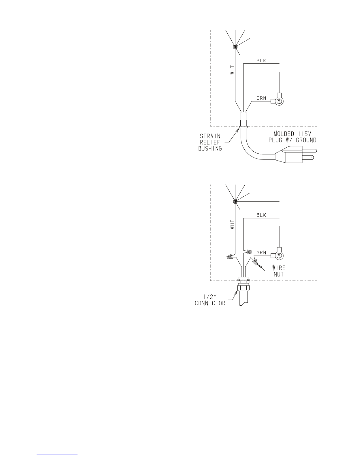
2.6 Hard Wiring the HI-E Dry 195
1. Remove the cabinet front to the left of the cord
mount.
2. Cut the cord near the strain relief bushing and
remove the cord and the strain relief bushing.
3. Trim and strip the wire ends for wire nuts.
4. Use a 1/2” connector to attach the hard wiring to the
HI-E Dry 195. Use a minimum of #3-14 wire. Comply
with all state and local code requirements.
5. Use wire nuts to attach the appropriate wire leads
Figure 1: Hard Wiring the HI-E Dry 195
3
www.DPJDLU.com • LQIR#DPJDLUFRPToll-Free 1-800-
Page 4
3 Operation
3.1 Humidity Control Adjustment
The dehumidifier will run continuously until the relative
humidity (RH) is reduced to the humidity control dial
setting. Setting the humidity control to lower RH levels
will NOT increase the unit’s dehumidification rate, it
will simply run longer to reduce the area’s RH to the
setting. The HI-E Dry 195 unit (and refrigerant based
dehumidifiers in general) will reduce a warm space’s RH
to a lower level than that of a cool space. It is therefore
pointless to set the humidity control to excessively low
levels in cool rooms. Doing so will result in long periods
of ineffective dehumidifier run time.
A quality humidity meter is recommended to accurately
monitor humidity levels. For a quote on a quality humidity
meter, call the factory.
3.2 Fan Switch
Turning the fan switch ON will cause the unit’s
internal blower to run continuously, whether the unit is
dehumidifying or not. This function is desirable if the unit
is used for air circulation or fresh air ventilation.
3.3 Defrost Control Adjustment
When the HI-E Dry 195 is used in a cool area, frost will
form on the cooling coil as it dehumidifies. When enough
frost forms, the defrost thermostat will initiate the
timed defrost cycle. The cycle periodically turns off the
compressor while allowing the blower to run. The air that
the blower draws through the cooling coil melts the frost.
The defrost cycle is automatic and designed for optimum
performance above 50°F. If the unit is used in an area
that is below 50°F for more than 2 hours, adjustment
of the defrost timer is recommended to improve
performance.
To adjust the defrost timer:
1. Unplug the unit.
2. Remove the front cover (6 screws).
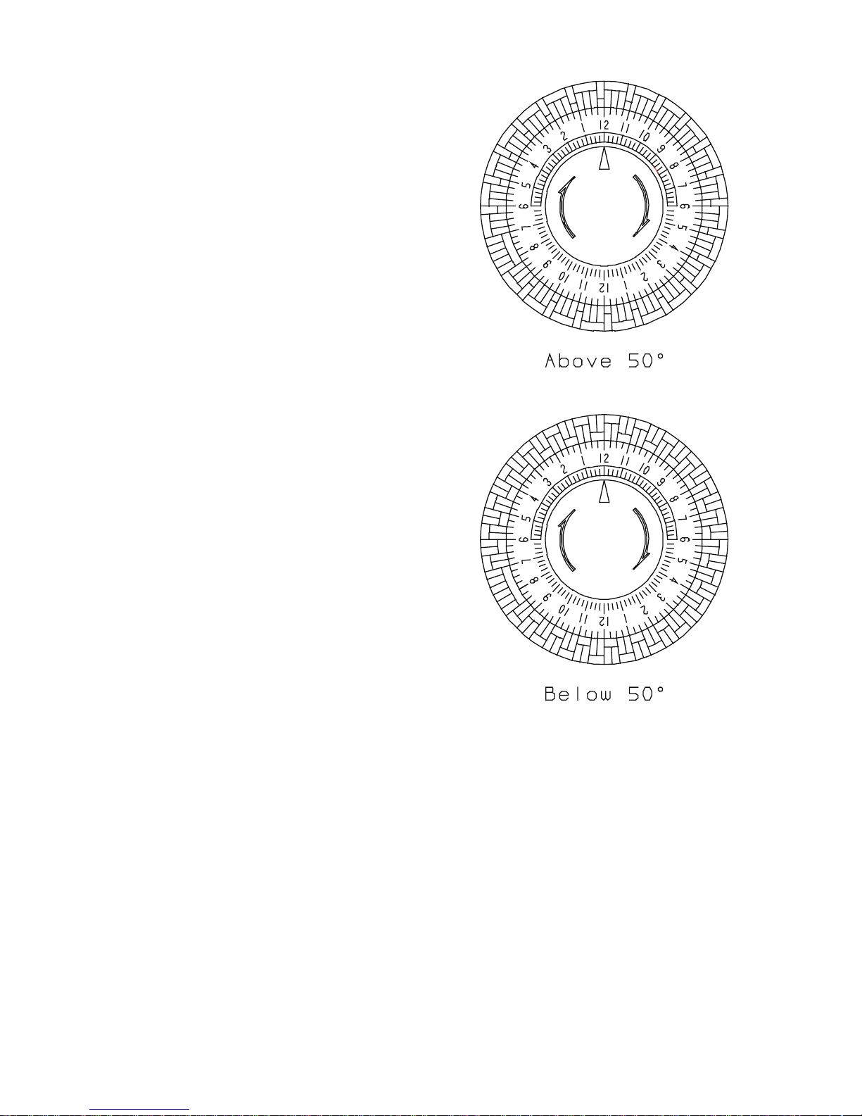
3. The timer is fastened to the base panel. Every fourth
peg around the dial is pushed out from the dial
center except one section with 5 pegs out in a row.
See figure 1. Each fourth “out” peg represents 15
minutes of compressor “off” time during every hour
that the unit is in the defrost cycle.
4. To improve performance below 50°F, the compressor
“off” time must be increased to 30 minutes per hour
to allow the frost to completely melt. To do this, push
the pegs out from the dial center so that the pegs
alternate with 2 toward the center, then 2 out from
the center, all the way around the dial except for the
section now with 6 pegs out in a row (see Fig. 1).
5. Replace the front cover.
Figure 2: Defrost Control Timer
Change the timer pegs back to the original pattern for
use above 50°F.
3.4 Low Pressure Control
If the low side refrigerant pressure drops to 15 PSIG, the
low pressure control opens and shuts off the compressor
and blower. It is an automatically reset control that will
close when the pressure rises to 35 PSIG. Its primary
function is to prevent damage to the compressor if a leak
develops in the refrigeration system. It may also open if
the unit is A) used in a cool area (below 50°F) and the
defrost timer is not adjusted (see Sec. 3.3) or B) stored
where it is below 40°F and then started. Under these
conditions, the unit will restart within several minutes.
Until the unit warms up, it may cycle several times.
4
www.DPJDLU.com • LQIR#DPJDLUFRPToll-Free 1-800-
Page 5
4 Maintenance
4.1 Air Filter
The HI-E Dry 195 is equipped with two 2” thick, 35%
efficient pleated fabric air filters that must be checked
regularly. Operating the unit with dirty filters will reduce
the dehumidifier’s capacity and efficiency and may cause
the compressor to cycle off and on unnecessarily on the
defrost control.
The filter can generally be vacuumed clean several times
before needing replacement. Replacement filters can be
ordered from the factory or purchased locally if available.
DO NOT operate the unit without the filter or with a less
effective filter as the heat exchange coils inside the unit
could become clogged and require disassembly to clean.
5 Service
CAUTION: Servicing the HI-E Dry 195 with its high-pressure
refrigerant system and high voltage circuitry presents a
health hazard which could result in death, serious bodily
injury, and/or property damage. Only qualified service
people should service this unit.
5.1 Warranty
A warranty certificate has been enclosed with this unit.
Read it before any repair is initiated. If a warranty repair
is required, call the factory first at 1-800-533-7533 for
warranty claim authorization and technical assistance.
5.2 Technical Description
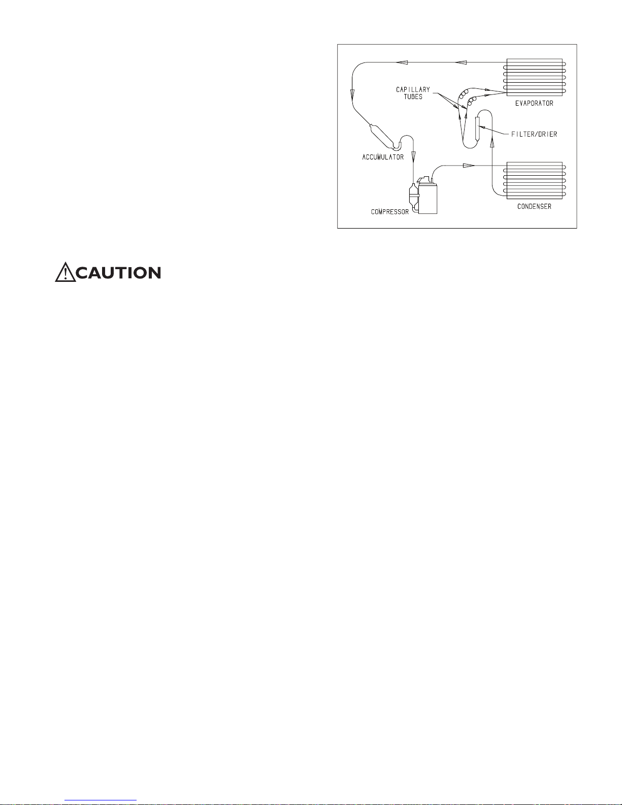
Refer to Figure 3. The HI-E Dry 195 uses a refrigeration
system similar to an air conditioner’s to remove heat and
moisture from incoming air, and add heat to the air that
is discharged.
Hot, high-pressure refrigerant gas is routed from the
compressor to the condenser coil. The refrigerant is
cooled and condensed by giving up its heat to the air that
is about to be discharged from the unit. The refrigerant
liquid then passes through two capillary tubes, which
cause the refrigerant pressure and temperature to drop.
It next enters the evaporator coil where it absorbs heat
from the incoming air and evaporates.
The evaporator operates in a flooded condition, which
means that it should always be full of liquid refrigerant
during normal operation. A flooded evaporator should
maintain constant pressure and temperature across the
entire coil, from inlet to outlet.
The mixture of gas and liquid refrigerant enter the
accumulator after leaving the evaporator coil. The
accumulator prevents any liquid refrigerant from reaching
the compressor. The compressor evacuates the cool
refrigerant gas from the accumulator and compresses
it to a high pressure and temperature to repeat the
process.
Figure 3: Refrigeration system of HI-E Dry 195
5.3 Troubleshooting
No dehumidification, neither blower nor compressor run
with fan switch OFF.
1. Unit unplugged or no power to outlet.
2. Humidity control set too high or defective (Sec. 3.1 &
5.9)
3. Loose connection in internal wiring.
4. Open low pressure control (Sec. 3.4 & 5.7)
Some dehumidification, blower runs continuously but
compressor only runs sporadically with fan switch OFF.
1. Unit is in defrost cycle (Sec. 3.3 & 5.10).
2. Defrost thermostat defective or loose
(Sec. 3.3 & 5.10).
3. Loose connection in compressor circuit
(see Fig. 4).
4. Defective compressor overload (Sec. 5.6A).
5. Defective compressor (Sec. 5.6).
6. Defective relay (Sec. 5.8).
7. Defective defrost timer (Sec. 5.10).
No dehumidification. Blower runs but compressor does
not with fan switch OFF.
1. Bad connection in compressor circuit (Fig. 4).
2. Defective compressor capacitor (Sec. 5.6A).
3. Defective compressor overload (Sec. 5.6A).
4. Defective compressor (Sec. 5.6).
5. Defective relay (Sec. 5.8).
6. Defective defrost timer (Sec. 5.10).
7. Bad connection in pump circuit (Fig. 4).
8. Pump float switch or safety switch open (Sec. 5.11).
9. Pump motor defective (Sec. 5.11).
5
www.DPJDLU.com • LQIR@DPJDLUFRPToll-Free 1-800-
Page 6

Blower does not run. Compressor runs briefly but cycles
on & off.
1. Loose connection in blower circuit (Fig. 4).
2. Obstruction prevents impeller rotation.
3. Defective blower (Sec. 5.5).
Unit removes some water but not as much as expected.
1. Air temperature and/or humidity have dropped.
2. Humidity meter and/or thermometer used are out of
calibration.
3. Unit has entered defrost cycle (Sec. 3.3 & 5.10).
4. Air filter dirty (Sec. 4.1).
5. Defrost timer incorrectly set for conditions
(Sec. 3.3 & 5.10).
6. Defective defrost thermostat (Sec. 5.10).
7. Low refrigerant charge (Sec. 5.4).
8. Air leak such as loose cover.
9. Defective compressor (Sec. 5.6).
10. Restrictive ducting (Sec. 2.4).
Pump does not pump water.
1. Hose kinked or plugged.
2. Pump check valve plugged (Sec. 5.11).
3. Bad connection in pump circuit (Fig. 4).
4. Hose disconnected internally.
Evaporator coil frosted continuously, low dehumidifying
capacity.
1. Defrost thermostat loose or defective
(Sec. 3.3 & 5.10).
2. Low refrigerant charge (Sec. 5.4).
3. Dirty air filters or airflow restricted. (Sec. 4.1).
4. Defrost timer set incorrectly (Sec. 3.3).
5.4 Refrigerant Charging
If the refrigerant charge is lost due to service or a leak,
a new charge must be accurately weighed in. If any of
the old charge is left in the system, it must be removed
before weighing in the new charge. Refer to the unit
nameplate for the correct charge weight and refrigerant
type. Add the refrigerant through the low side service
port (See Fig. 5).
5.5 Blower Replacement
The centrifugal blower has a PSC motor and internal
thermal overload protection. If defective, the complete
assembly must be replaced.
1. Unplug the power cord.
2. Remove the cabinet front (6 screws).
3. If an outlet duct is connected to the unit, remove it.
4. Disconnect the blower leads: white from the
compressor run capacitor, and black connected to
the fan switch.
5. Remove the nuts & bolts holding the blower outlet
flange to the cabinet end and remove the blower.
6. Reassembling with the new blower is the above
procedure reversed.
5.6 Compressor/Capacitor Replacement
This compressor is equipped with a two terminal external
overload, run capacitor, but no start capacitor or relay
(see Fig. 4).
CAUTION-ELECTRICAL SHOCK HAZARD: Electrical power
must be present to perform some tests; these tests
should be performed by a qualified service person.
5.6A Checking Compressor Motor Circuits
Perform the following tests if the blower runs but the
compressor does not with the humidity control ON.
1. Turn the humidity control OFF and unplug the unit,
remove the cabinet front (6 screws).
2. Plug in the unit and turn the humidity control ON. Use
a voltmeter to check for 110 to 120 volts between
(a) the relay terminal that the black wire from the
compressor connects to and (b) the capacitor
terminal with the (2) white wires, (1) red wire & (1)
brown wire connected. If voltage is present, go to
step 3. If no voltage, the low pressure control, the
defrost thermostat, the relay or the condensate
pump safety switch are open or there is a loose
connection in the compressor circuit. Test each
component for continuity; see the appropriate
section if a defect is suspected
3. Turn the humidity control OFF and unplug the unit,
then disconnect the red and yellow wires from
compressor terminals R & S. Using an ohmmeter
check continuity between the points listed below.
4. Compressor terminals C and S: No continuity
indicates an open start winding; the compressor
must be replaced.
5. Compressor terminals C and R: No continuity
indicates an open run winding; the compressor must
be replaced.
6. Compressor terminal C and overload terminal 1: No
continuity indicates a defective overload lead.
7. Overload terminals 1 and 3: If there is no continuity,
the overload may be tripped; wait 10 minutes and try
again. If there is still no continuity, it is defective and
must be replaced.
8. Compressor terminal C and compressor case:
Continuity indicates a grounded motor; the
compressor must be replaced.
6
www.DPJDLU.com • LQIR@DPJDLU.comToll-Free 1-800-
Page 7

9. Disconnect the wires from the capacitor. Set the
ohmmeter to the Rx1 scale; the capacitor is shorted
and must be replaced if continuity exists across its
terminals. If there is no needle movement with the
meter set on the Rx100000 scale, the capacitor is
open and must be replaced.
10. Reconnect the wires to the compressor and
capacitor; plug in and turn on the unit. If the
compressor fails to start, replace the run capacitor.
11. If the unit still does not start, adding a hard-start kit
will provide greater starting torque. If this does not
work, the compressor has an internal mechanical
defect and must be replaced.
5.6B Replacing a Burned Out Compressor
The refrigerant and oil mixture in a compressor
is chemically very stable under normal operating
conditions. However, when an electrical short occurs in
the compressor motor, the resulting high temperature
arc causes a portion of the refrigerant oil mixture to
break down into carbonaceous sludge, a very corrosive
acid, and water. These contaminants must be carefully
removed otherwise even small residues will attack
replacement compressor motors and cause failures.
The following procedure is effective only if the system is
monitored after replacing the compressor to insure that
the clean up was complete.
1. This procedure assumes that the previously listed
compressor motor circuit tests revealed a shorted or
open winding. If so, cautiously smell the refrigerant
from the compressor service port for the acid odor
of a burn out. WARNING: The gas could be toxic and
highly acidic. If no acid odor is present, skip down to
the section on changing a non-burn out compressor.
2. Remove and properly dispose of the system charge.
DO NOT vent the refrigerant or allow it to contact your
eyes or skin.
3. Remove the burned out compressor. Use rubber
gloves if there is any possibility of coming in contact
with the oil or sludge.
4. To facilitate subsequent steps, determine the type of
burn out that occurred. If the discharge line shows
no evidence of sludge and the suction line is also
clean or perhaps has some light carbon deposits,
the burn out occurred while the compressor was not
rotating. Contaminants are therefore largely confined
to the compressor housing. A single installation of
liquid and suction line filter/driers will probably clean
up the system.
If sludge is evident in the discharge line, it will
likely be found in the suction line; this indicates the
compressor burned out will running. Sludge and acid
have been pumped throughout the system. Several
changes of the liquid and suction filter/driers will
probably be necessary to cleanse the system.
5. Correct the system fault that caused the burn out.
Consult the factory for advice.
6. Install the replacement compressor with a new
capacitor and an oversized liquid line filter.
In a running burn out, install an oversized suction line
filter/drier between the accumulator and compressor.
Thoroughly flush the accumulator with refrigerant to
remove all trapped sludge and to prevent the oil hole
from becoming plugged. A standing burn out does
not require a suction line filter/drier.
7. Evacuate the system with a good vacuum pump and
accurate vacuum gauge. Leave the pump on the
system for at least an hour.
8. Operate the system for a short period of time,
monitoring the suction pressure to determine that
the suction filter is not becoming plugged. Replace
the suction filter/drier if pressure drop occurs. If a
severe running burn out has occurred, several filter/
driers may have to be replaced to remove all of the
acid and moisture.
NOTE: NEVER use the compressor to evacuate the system
or any part of it.
5.6C Replacing a Compressor- Non-Burn Out
Remove the refrigerant from the system. Replace the
compressor and liquid line filter/drier. Charge the system
to 50 PSIG and check for leaks. Remove the charge and
weigh in the refrigerant quantity listed on the nameplate.
Operate the system to verify performance.
5.7 Low Pressure Control
If the low side refrigerant pressure drops to 15 PSIG, the
low pressure control opens and shuts off the compressor
and blower. It is an automatically reset control. It will
close when the refrigerant pressure rises to 35 PSIG. Its
primary function is to prevent damage to the compressor
if a leak develops in the refrigeration system. It may also
open if the unit is A) used in a cool area (below 50°F)
and the defrost timer is not adjusted (see Sec. 3.3) or
B) stored where it is below 40°F and then started. Under
these conditions, the unit will restart within several
minutes. Until the unit warms up, it may cycle several
times.
5.8 Relay
The contacts of the single pole, single throw relay
complete the power circuit to the compressor. The
contacts are closed when power is provided to the relay
coil via the control circuit. The control circuit includes the
humidity control, low pressure control, defrost thermostat
and timer.
7
www.DPJDLU.com • LQIR@DPJDLUFRPToll-Free 1-800-
Page 8

5.9 Humidity Control
The humidity control is an adjustable switch that closes
when the relative humidity of the air in which it is located
rises to the dial set point. It opens when the RH drops 4
to 6% below the set point.
5.10 Defrost Thermostat & Timer
The defrost thermostat is attached to the refrigerant
suction tube between the accumulator and compressor.
If the low side refrigerant temperature drops due to
excessive frost formation on the evaporator coil, the
thermostat opens. The compressor is then cycled off
and on by the defrost timer. The blower will continue to
run, causing air to flow through the evaporator coil and
melt the ice when the compressor is off. When the air
temperature and/or humidity increase, the evaporator
temperature will rise and the thermostat will close to end
the defrost cycle.
To improve performance in low temperatures, see Sec.
3.3 for defrost timer adjustment.
5.11 Condensate Pump
Condensate is automatically pumped when the water
level in the pump’s reservoir rises to close the float
switch.
If the pump is unable to empty its reservoir due to a
pump failure or blocked condensate hose, a pump safety
float switch is triggered before the reservoir overflows.
The switch turns off the compressor via its relay.
To replace the condensate pump:
1. Unplug the unit & remove the front cover.
2. Disconnect the 2 hoses from the pump.
3. Cut the pump lead wires near the old pump.
4. Remove the 2 nuts from the unit side that hold the
pump to the side.
5. Attach the new pump with 2 nuts.
6. Connect the new pump wiring.
7. Connect the hoses to the new pump. Carefully
route the hoses so they do not contact the copper
refrigerant lines or the compressor shell.
Figure 4: Electrical Schematic of HI-E Dry 195
8
www.DPJDLU.com • LQIR@DPJDLU.comToll-Free 1-800-
Page 9

SERVICE PARTS: HI-E Dry 195 Dehumidifier
ITEM PART NO. QTY. DESCRIPTION
1 4021083 1 Blower with Capacitor
2 4022740 1 Capacitor, Run, 30MFD, 370v
3 4017777 2 Capillary Tubes, .059” ID x 32” long
4 4023604 4 Caster, 2”, Plastic, Swivel
5 4023533 1 Coil, Condenser
6 4023534 1 Coil, Evaporator
7 4025738 1 Compressor Service Assembly
4022595 1 Compressor Overload
8 4023649 1 Condensate Pump
9 4023646 1 Condensate Pump Reservoir
10 4022219 1 Control, Low Pressure
11 4023495 1 Cord & Wire Harness
12 4021470 1 Defrost Thermostat
4021648 1 Defrost Thermostat Mounting Clip
13 4021823 1 Defrost Timer (4021823)
14 4023603 1 Duct Collar Kit, Optional
15 4021799 2 Filter, Air (2” X 16” X 16”), (Grainger P/N 6B958)
16 4025087 1 Filter/Drier
17 4017152 1 Hose, Drain, .38” x 20’ long
18 4021689 1 Hose, Drain Pan, .56” ID x 16” long (not shown)
19 4021469 1 Humidity Controller, Internal
4021495 1 Knob
20 4020175 Humidity Controller, Remote, Optional, (Honeywell H46C1000)
21 1096010 6 Machine Screw, Stainless Steel, ¼-20 X 1” (for Front Cover)
22 1970010 1 Relay, SPDT (Omron G7L-1A-TUB-CB-AC100/120)
23 4023549 6 Self-Retaining Nut, ¼-20
24 4020988 1 Service Valve Assembly w/ Core & Cap
25 4025560 1 Switch, SPDT, On-Off, for Fan
26 4021818 1 Accumulator
4023609 1 Wiring Diagram (NS)
9
www.DPJDLU.com • LQIR@DPJDLU.comToll-Free 1-800-
Page 10
Therma-Stor HI-E DRY Dehumidifier Limited Warranty
Warrantor:
Therma-Stor LLC
PO Box 8680
Madison, WI 53708
Telephone: 1-800-533-7533
Who Is Covered: This warranty extends only to the original end-user of the HI-E DRY dehumidifier, and
may not be assigned or transferred.
Year One: Therma-Stor warrants that, for one (1) year the HI-E DRY dehumidifier will operate free
from any defects in materials and workmanship, or Therma-Stor will, at its option, repair or replace
the defective part(s), free of any charge.
Year(s) Two Through Five: Therma-Stor further warrants that for a period of five (5) years, the
condenser, evaporator, and compressor of the HI-E DRY dehumidifier will operate free of any defects
in material or workmanship, or Therma-Stor, at its option, will repair or replace the defective part(s),
provided that all labor and transportation charges for the part(s) shall be borne by the end-user.
End-User Responsibilities: Warranty service must be performed by a Servicer authorized by ThermaStor. If the end-user is unable to locate or obtain warranty service from an authorized Servicer, he
should call Therma-Stor at the above number and ask for the Therma-Stor Service Depar tment,
which will then arrange for covered warranty service. Warranty service will be performed during
normal working hours.
The end-user must present proof of purchase (lease) upon request, by use of the warranty card or
other reasonable and reliable means. The end-user is responsible for normal care. This warranty
does not cover any defect, malfunction, etc. resulting from misuse, abuse, lack of normal care,
corrosion, freezing, tampering, modification, unauthorized or improper repair or installation, accident,
acts of nature or any other cause beyond Therma-Stor’s reasonable control.
Limitation and Exclusions: If any HI-E DRY Dehumidifier part is repaired or replaced, the new part
shall be warranted for only the remainder of the original warranty period applicable thereto (but all
warranty periods will be extended by the period of time, if any, that the HI-E DRY Dehumidifier is out
of service while awaiting covered warranty service).
UPON THE EXPIRATION OF THE WRITTEN WARRANTY APPLICABLE TO THE HI-E DRY DEHUMIDIFIER
OR ANY PART THEREOF, ALL OTHER WARRANTIES IMPLIED BY LAW, INCLUDING MERCHANTABILITY
AND FITNESS FOR A PARTICULAR PURPOSE, SHALL ALSO EXPIRE. ALL WARRANTIES MADE BY
THERMA-STOR ARE SET FORTH HEREIN, AND NO CLAIM MAY BE MADE AGAINST THERMA-STOR
BASED ON ANY ORAL WARRANTY. IN NO EVENT SHALL THERMA-STOR, IN CONNECTION WITH THE
SALE, INSTALLATION, USE, REPAIR OR REPLACEMENT OF ANY HI-E DRY DEHUMIDIFIER OR PART
THEREOF BE LIABLE UNDER ANY LEGAL THEORY FOR ANY SPECIAL, INDIRECT OR CONSEQUENTIAL
DAMAGES INCLUDING WITHOUT LIMITATION WATER DAMAGE (THE ENDUSER SHOULD TAKE
PRECAUTIONS AGAINST SAME), LOST PROFITS, DELAY, OR LOSS OF USE OR DAMAGE TO ANY REAL
OR PERSONAL PROPERTY.
Some states do not allow limitations on how long an implied warranty lasts, and some do not allow
the exclusion or limitation of incidental or consequential damages, so one or both of these limitation
may not apply to you.
Legal Rights: This warranty gives you specific legal rights, and you may also have other rights which
vary from state to state.may not apply to you.
11
TS-185
www.amgair.com • info@amgair.com Toll-Free 1-800-782-9175
 Loading...