

Page 1
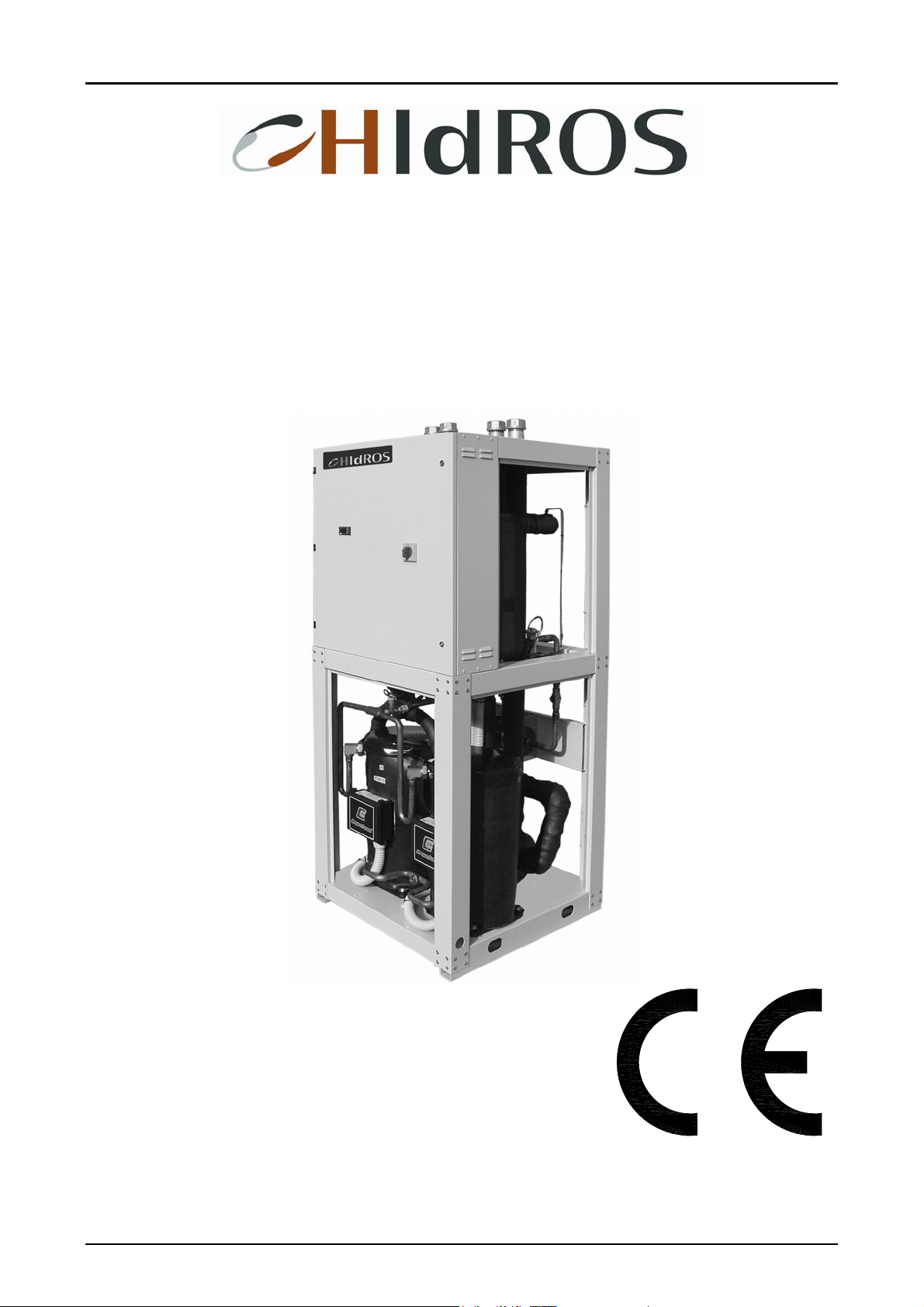
GROUND SOURCE HEAT PUMPS
WDH
SERIES
TECHNICAL MANUAL
Page 2

WDH Ground source heat pumps
MTWDHGB REV.072008
2
Page 3

WDH Ground source heat pumps
MTWDHGB REV.072008
3
Page 4

WDH Ground source heat pumps
MTWDHGB REV.072008
4
Page 5

WDH Ground source heat pumps
INDEX
INDEX
Declaration of conformity page 3
Aim and contents of this manual page 6
How to keep this manual page 6
Graphic symbols page 6
Safety laws page 7
General safety guidelines page 7
Workers’ health and safety page 8
Protective equipment page 8
Safety signs page 8
Technical characteristics page 9
Technical data page 11
WDH heating capacity and compressors input power page 12
WDH/RV cooling capacity and compressors input power page 16
Domestic hot water production page 19
Source side heat exchangers water pressure drops page 20
User side heat exchangers water pressure drops page 21
Refrigerant layouts page 22
Free cooling capacities page 26
Partial heat recovery capacity page 27
Water pumps available static pressure page 28
Operation limits page 29
Compressors capacity step controls page 30
Corrections tables page 30
Sound Data page 31
Safety Device Setting page 32
Electric data page 32
Inspection page 32
Lifting and handling page 32
Location and minimum technical clearances page 33
Hydraulic circuit page 34
Unit display page 35
Electrical connections page 36
Start up page 36
Maintenance and periodic checks page 37
Refrigerant circuit repair page 38
Environment protection page 38
Unit out of service page 38
Fault finding page 38
Dimensions page 39
MTWDHGB REV.072008
5
Page 6
WDH Ground source heat pumps
The WDH manual, contains any information that is needed for a correct use of the equipment while safeguarding operator safety,
according to what indicated in the actual directives on units safety.
This manual provides basic information on the installation, operation and maintenance off the WDH unit. It is addressed to machine
operators and it enables them to use the equipment efficiently, even if they do not have any previous specific knowledge of it.
This manual describes the characteristics of the equipment at the time it is being put on the market; therefore it may not capture later
technological improvements introduced by HIDROS SRL as part of its constant endeavour to enhance the performance, ergonomics,
safety and functionality of its products.
The manual must be always with the unit it refers to. It must be stored in a safe place, away from the dust and moisture. It must be
accessible to all users who shall consult it any time they are in doubt on how to operate the equipment.
HIDROS SRL reserves the right to modify its products and related manuals without necessarily updating previous versions of the
reference material. The customer shall store any updated copy of the manual or parts of it delivered by the manufacturer as an
attachment to this manual.
HIDROS SRL is available to give any detailed information about this manual and to give information regarding the use and the
maintenance of its own units.
AIM AND CONTENTS OF THIS MANUAL
HOW TO KEEP THIS MANUAL
GRAPHIC SYMBOLS
Indicates operations that can be dangerous for people and/or disrupts the correct operation of the
equipment..
Indicates prohibited operations.
Indicates important information that the operator must follow in order to guarantee the correct operation
of the equipment in complete safety
MTWDHGB REV.072008
6
Page 7
WDH Ground source heat pumps
The units single components or the complete units produced by HIDROS have been designed according to the actual CE and
national Directives. For the detailed list of the project technical Directives, refer to the CE declaration enclosed.
Before beginning to operate on WDH units every user must be perfectly knowledgeable about the functions of the equipment and its
controls and must have read and understood the information container in this manual.
It’s strictly forbidden to remove and/or camper with any safety device.
SAFETY LAWS
GENERAL SAFETY GUIDELINES
Any routine or not-routine maintenance operation shall be carried out when the equipment has been shut
down, disconnected from electric and pneumatic power source and after its pneumatic system has been
discharged.
Do not put your hands or insert screwdrivers, spanners or other tools into moving parts of the equipment.
The equipment supervisor and the maintenance man must receive training suitable for the performance of
their tasks in safety
Operators must know how to use personal protective devices and must know the accident-prevention
guidelines contained in national and international laws and norms.
MTWDHGB REV.072008
7
Page 8
WDH Ground source heat pumps
The European Community has emanated some Directives about worker’s safety and health which the employers have to respect
and make the others respect. For the detailed list, see the CE declaration enclosed.
Do not tamper with or replace parts of the equipment without the specific consent of the manufacturer.
The manufacturer shall have no responsibility whatsoever in case of unauthorised operations.
When operating and maintaining the WDH unit, use the following personal protective equipment.
Using components, expendable materials or spare parts that do not correspond to those recommended
by the manufacturer and/or listed in this manual may be dangerous for the operators and/or damage the
equipment
The operator’s workplace must be kept clean, tidy and free from objects that may camper free
movements. Appropriate lighting of the work place shall be provided so as to allow the operator to carry
out the required operations safely. Poor or too strong lighting can cause risks.
Ensure that work places are always adequately ventilated and that aspirators are working, in good
condition and in compliance with the requirements of the laws in force...
WORKERS’ HEALTH AND SAFETY
PERSONAL PROTECTIVE EQUIPMENT
Equipment: people who make maintenance or work with the unit, must wear an equipment in accordance
with the safety Directives. They must wear accident prevention shoes with anti-slip sole where the paving
is slippery.
The equipment features the following safety signs, which must be complied with:
Gloves: During the cleanings and the maintenance operations, it’s necessary the use of appropriate
gloves. In case of gas recharge, it’s compulsory the use of appropriate gloves to avoid the risk of
freezing.
Mask and googles: Respiratory protection (mask) and eye protection (goggles) should be
used during cleaning and maintenance operations.
SAFETY SIGNS
General hazard
Electric shock hazard
MTWDHGB REV.072008
8
Page 9

WDH Ground source heat pumps
TECHNICAL CHARACTERISTICS
The WDH ground source heat pump units have been designed to guarantee high heating capacities with excellent efficiencies; units
are suitable either for heating or domestic hot water production.
WDH heat pumps have been optimised for applications in
buildings where water temperature demand for space heating is around 50°C. The WDH heat pumps allows to efficiently
produce water temperature up to 60°C during cold winter time. This new technology in space heating and tap water production
allows traditional boilers to be replaced by Heat Pumps in retrofit applications without changing the radiators.
Frame
All WDH units are made from hot-galvanised thick sheet metal, painted with polyurethane powder enamel at 180°C to ensure the
best resistance against the atmospheric agents. The frame is self-supporting with removable panels. All screws and rivets are in
stainless steel. The colour of the units is RAL 7035.
Refrigerant circuit
The refrigerant gases used in these units is R407C. The refrigerant circuit is made by using international primary brands components
and according to ISO 97/23 concerning welding procedures. Each refrigerant circuit is totally independent from the other. Any
incorrect operation of one circuit does not influence the other circuit. The refrigerant circuit includes:
• sight glass,
• filter drier,
• thermal expansion valve with external equalizer,
• Schrader valves form maintenance and control,
• pressure safety device (according to PED regulation).
Compressors
The WDH units are supplied with scroll type compressors, optimized for heating applications
allows extreme high efficiencies especially when the heat source temperature is low. Compressors are supplied with
crankcase heater and thermal overload protection by a klixon embedded in the motor winding. The compressors used are all in
tandem execution. This solution allows much higher efficiencies in partial loads compared to the units with independent refrigerant
circuits. In all units the crankcase heaters are always powered when the compressors are in stand-by. The inspection is possible
through the frontal panel of the unit that allows the maintenance of the compressors even if the unit is working.
Source side heat exchangers
The source side heat exchangers are made of AISI 316 stainless steel braze-welded plates type. From size 039 to size 162 they are
single water side circuit, from the size 144 they are double circuit “cross flow” type. The use of these kind of heat exchangers allows
a massive reduction of the refrigerant charge of the unit compared to the traditional shell-in-tube ones and increases the efficiency of
the refrigerant cycle in partial loads. The source heat exchangers are factory insulated with flexible close cell material and are
provided with a temperature sensor as antifreeze protection.
User side heat exchangers
The user side heat exchangers are made of AISI 316 stainless steel braze-welded plates type. From size 039 to size 162 they are
single water side circuit, from the size 144 they are double circuit “cross flow” type. All units are supplied with sub-cooler to enhance
the performance of the refrigerant cycle. The user heat exchangers are factory insulated with flexible close cell material.
Electric enclosure
The electric switch board is made according to electromagnetic compatibility norms CEE 73/23 and 89/336. The accessibility to the
board is possible after removing the front panel of the unit and the OFF positioning of the main switch. The moisture protection
degree is IP55. In all WDH units are installed, standard, the compressors sequence relay who disables the operation of the
compressor in case the power supply phase sequence is not the correct one (scroll compressors in fact, can be damaged if they
rotate reverse wise). The following components are also standard installed: main switch, magnetic-thermal switches as a protection
of compressors and pumps (where present), control circuit automatic breakers, compressor contactors, pump contactors. The
terminal board is supplied with voltage free contacts for remote ON-OFF, Summer / winter change over and general alarm.
Microprocessors
All WDH units are supplied standard with microprocessor controls. The microprocessor controls the following functions: regulation of
the water temperature, antifreeze protection, compressor timing, compressor automatic starting sequence, alarm reset, potential free
contact for remote general alarm, alarms and operation leds. Upon request any microprocessor can be connected to a BMS system
for the remote control and management. The technical department is available to study, together with the customer, different
solutions using MODBUS; LONWORKS; BACNET or TREND protocols.
with a special scroll design who
MTWDHGB REV.072008
9
Page 10

WDH Ground source heat pumps
Control and protection devices
All units are supplied with the following control and protection devices: Return and supply user heat exchanger sensors, return and
supply source heat exchanger sensors, high pressure switch with manual reset, low pressure switch with automatic reset, high
pressure safety valve, compressor thermal overload protection, pump thermal overload protection (when present), source heat
exchanger flow switch.
OTHER VERSIONS
WDH/A1NT UNIT WITH WATER PUMP
This version is supplied with a single centrifugal type water pump with a high available pressure. The pump is connected, standard,
to the user heat exchanger but, upon request, can also be connected to the source heat exchanger
WDH/RV/SW6 UNIT WITH DOMESTIC HOT WATER PRODUCTION (SW6) – 6 PIPE WATER CONNECTIONS
This version is suitable to produce domestic hot water: the unit is supplied with an additional heat exchanger used as condenser for
the domestic hot water that, is independendt from the operation mode of the unit. The activation of the additional heat exchanger is
done automatically by the microprocessor control when the domestic hot water temperature measured by the sensor is lower than
the required set point. This unit is supplied, standard, with a reverse cycle valve to allow even the production of cold water in summer
mode.
WDH/SW5 UNIT WITH DOMESTIC HOT WATER PRODUCTION (SW5) – 5 PIPE WATER CONNECTIONS
This version is suitable to produce domestic hot water: the unit is supplied with an ON/OFF 3 way valve to deviate the water flow in
a water accumulator; the activation of the 3 way valve is done automatically by the microprocessor control when the domestic hot
water temperature in the accumulator is lower than the required set point.
WDH/FC – WDH/FC/SW5 – WDH/FC/RV/SW6 FREE COOLING VERSIONS
These versions in addition to the standard characteristics are suitable for cold water production during summer operation using the
cold water flow coming from the ground probes. During free cooling mode the compressors are not working; the system is supplied
with an intermediate heat exchanger and a modulating 3 way valve who manage the water flow to the user circuit depending on the
required cold water temperatures.
WDH/RV REVERSIBLE VERSION
This version is suitable for cooling during summer operation by using a 4 way reverse cycle valve in the refrigerant circuit.
WDH/LS LOW NOISE VERSION
The low noise versions LS include the complete acoustic insulation of the unit (compressor + heat exchangers vanes with insulating
material having high density media with the interposition of heavy bitume layer.
MTWDHGB REV.072008
10
Page 11
WDH Ground source heat pumps
WDH TECHNICAL DATA
Mod. 039 045 050 060 070 080 090 110 120 130
Refrigerant R407C R407C R407C R407C R407C R407C R407C R407C R407C R407C
Heating capacity Kw 48,2 58,7 67,9 75,8 83,7 101,7 118,4 135,2 152,3 169,5
Compressors input power Kw 9,4 11,4 12,9 14,6 16,2 19,4 22,5 25,7 28,9 32,1
C.O.P. W/W 5,1 5,1 5,3 5,2 5,2 5,2 5,3 5,3 5,3 5,3
User water flow rate l/h 8300 10100 11700 13100 14400 17500 20400 23300 26200 29200
Source water flow rate l/h 6680 8140 9460 10530 11650 14170 16500 18850 21230 23640
Total input current A
Total peak current A
Maximum input current A
Power suppy V/Ph/Hz 400/3/50
Compressor
Refrigerant circuit n° 1 1 1 1 1 1 1 1 1 1
Step controls n° 2 2 2 2 2 2 2 2 2 2
Sound power level
Sound pressure level
Water pump (option) Kw 1,1 1,1 1,1 1,1 1,1 1,5 1,5 2,2 2,2 2,2
Water pump input current A 2,9 2,9 2,9 2,9 2,9 2,9 4,3 5,3 5,3 5,3
Weight (Standard configuration) Kg 470 500 520 540 570 590 650 660 720 770
(1)
dB(A) 80 80 81 82 82 83 83 84 84 85
(2)
dB(A) 52 52 53 54 54 55 55 56 56 57
type Scroll
n° 2 2 2 2 2 2 2 2 2 2
Mod. 152 162 144 164 190 210 240 260 300 320
Refrigerant R407C R407C R407C R407C R407C R407C R407C R407C R407C R407C
Heating capacity Kw 189,1 208,7 185,4 203,4 236,8 270,3 304,7 339,1 378,2 417,4
Compressors input power Kw 35,2 38,3 35,6 38,7 45,1 51,4 57,8 64,2 70,3 76,5
C.O.P. W/W 5,4 5,4 5,2 5,3 5,3 5,3 5,3 5,3 5,4 5,5
User water flow rate l/h 32550 35900 32000 35000 40800 46500 52500 58400 65100 71800
Source water flow rate l/h 26500 29400 25800 28400 33000 37700 42500 47300 53000 58700
Total input current A
Total peak current A
Maximum input current A
Power suppy V/Ph/Hz 400/3/50
Compressor
Refrigerant circuit n° 1 1 2 2 2 2 2 2 2 2
Step controls n° 2 2 4 4 4 4 4 4 4 4
Sound power level
Sound pressure level
Water pump (option) Kw 2,2 2,2 2,2 3,0 3,0 3,0 4,0 4,0 4,0 5,5
Water pump input current A 5,3 5,3 5,3 9,6 9,6 9,6 9,6 9,6 9,6 13,2
Weight (Standard configuration) Kg 790 820 980 1030 1150 1190 1250 1320 1400 1490
(1)
dB(A) 85 85 85 85 86 88 88 88 90 90
(2)
dB(A) 57 57 57 57 58 60 60 60 62 62
type Scroll
n° 2 2 4 4 4 4 4 4 4 4
Performances are referred to the following conditions:
Heating: User water temperature in/out 35/30 °C, Source water temperature in/out 10/5°C.
(1): Sound power level according to ISO 3746.
(2): Sound pressure level measured at 10 mt from the unit in free field conditions direction factor Q=2 according to ISO 3746.
27,0 30,6 32,0 34,7 37,4 47,2 53,9 58,4 67,3 76,4
116,0 143,0 149,0 189,0 194,0 230,0 257,0 266,0 313,0 324,0
34,0 40,0 44,0 49,0 54,0 64,0 73,0 82,0 93,0 104,0
83,9 91,4 86,0 94,4 105,0 122,4 134,6 152,8 167,8 182,8
362,0 372,5 279,8 294,0 330,0 348,0 406,0 428,0 476,5 497,5
114,5 125,0 109,6 128,0 146,0 164,0 186,0 208,0 229,0 250,0
MTWDHGB REV.072008
11
Page 12
WDH Ground source heat pumps
HEATING CAPACITY AND COMPRESSORS INPUT POWER
TWIE
Mod.
039
Mod.
045
Mod.
050
Mod.
060
Mod.
070
TWIE: Source inlet water temperature (°C)
TWUE: Source outlet water temperature (°C)
TWUC: User outlet water temperature (°C) (Dt=5°C)
PH: Heating capacity (Kw
PA: Compressors input power (Kw)
TWUE
(°C)
(°C)
0 -5
2 -3
5 0
7 2
10 5
13 8
15 10
20 15
TWIE
TWUE
(°C)
(°C)
0 -5
2 -3
5 0
7 2
10 5
13 8
15 10
20 15
TWIE
TWUE
(°C)
(°C)
0 -5
2 -3
5 0
7 2
10 5
13 8
15 10
20 15
TWIE
TWUE
(°C)
(°C)
0 -5
2 -3
5 0
7 2
10 5
13 8
15 10
20 15
TWIE
TWUE
(°C)
(°C)
0 -5
2 -3
5 0
7 2
10 5
13 8
15 10
20 15
35 40 45 50 55 60 35 40 45 50 55 60 35 40 45 50 55 60
34,4 33,8 33,4 9,6 10,7 12,0 3,6 3,1 2,8
36,8 36,1 35,6 35,2 9,6 10,7 12,0 13,4 3,8 3,4 3,0 2,6
40,8 39,9 39,2 38,7 9,5 10,7 12,1 13,5 4,3 3,7 3,3 2,9
43,6 42,6 41,8 41,2 40,7 9,5 10,7 12,1 13,6 15,3 4,6 4,0 3,5 3,0 2,7
48,2 47,0 46,0 45,1 44,5 9,4 10,6 12,0 13,6 15,3 5,1 4,4 3,8 3,3 2,9
53,3 51,8 50,5 49,4 48,6 48,0 9,4 10,6 12,0 13,6 15,4 17,4 5,7 4,9 4,2 3,6 3,2 2,8
57,0 55,3 53,8 52,5 51,5 50,7 9,4 10,5 11,9 13,5 15,4 17,4 6,1 5,2 4,5 3,9 3,4 2,9
67,3 64,9 62,9 61,1 59,6 58,3 9,5 10,5 11,8 13,4 15,3 17,4 7,1 6,2 5,3 4,5 3,9 3,4
35 40 45 50 55 60 35 40 45 50 55 60 35 40 45 50 55 60
42,5 41,9 41,3 11,5 12,8 14,3 3,7 3,3 2,9
45,4 44,6 43,9 43,3 11,5 12,8 14,3 15,9 4,0 3,5 3,1 2,7
50,0 49,0 48,1 47,2 11,5 12,8 14,3 16,0 4,4 3,8 3,4 3,0
53,4 52,2 51,1 50,1 49,3 11,4 12,8 14,3 16,0 17,9 4,7 4,1 3,6 3,1 2,8
58,7 57,3 56,0 54,7 53,7 11,4 12,8 14,3 16,1 18,0 5,1 4,5 3,9 3,4 3,0
64,6 62,9 61,3 59,8 58,4 57,2 11,4 12,8 14,3 16,1 18,0 20,2 5,7 4,9 4,3 3,7 3,2 2,8
68,9 66,9 65,1 63,5 61,9 60,5 11,4 12,8 14,3 16,1 18,0 20,2 6,1 5,2 4,5 3,9 3,4 3,0
80,5 78,1 75,8 73,5 71,4 69,5 11,3 12,7 14,3 16,1 18,1 20,3 7,1 6,1 5,3 4,6 3,9 3,4
35 40 45 50 55 60 35 40 45 50 55 60 35 40 45 50 55 60
49,5 48,6 47,7 13,1 14,6 16,1 3,8 3,3 3,0
52,7 51,7 50,7 49,8 13,1 14,6 16,3 18,0 4,0 3,5 3,1 2,8
58,0 56,8 55,6 54,5 13,0 14,6 16,4 18,2 4,4 3,9 3,4 3,0
61,8 60,4 59,1 57,8 56,6 13,0 14,6 16,4 18,3 20,4 4,7 4,1 3,6 3,2 2,8
67,9 66,2 64,7 63,2 61,8 12,9 14,6 16,4 18,4 20,5 5,2 4,5 3,9 3,4 3,0
74,5 72,6 70,8 69,0 67,3 65,7 12,9 14,5 16,4 18,4 20,6 23,1 5,8 5,0 4,3 3,7 3,3 2,8
79,3 77,2 75,1 73,2 71,3 69,5 12,8 14,5 16,3 18,4 20,7 23,2 6,2 5,3 4,6 4,0 3,4 3,0
92,7 89,8 87,2 84,6 82,2 79,9 12,8 14,4 16,2 18,3 20,7 23,3 7,3 6,3 5,4 4,6 4,0 3,4
35 40 45 50 55 60 35 40 45 50 55 60 35 40 45 50 55 60
55,2 54,2 53,4 14,6 16,3 18,2 3,8 3,3 2,9
58,9 57,7 56,7 55,8 14,6 16,4 18,3 20,3 4,0 3,5 3,1 2,7
64,7 63,4 62,1 61,0 14,6 16,4 18,4 20,5 4,4 3,9 3,4 3,0
69,0 67,4 66,0 64,6 63,4 14,6 16,4 18,4 20,6 23,0 4,7 4,1 3,6 3,1 2,8
75,8 73,9 72,2 70,6 69,1 14,6 16,4 18,4 20,7 23,2 5,2 4,5 3,9 3,4 3,0
83,3 81,1 79,0 77,0 75,2 73,5 14,6 16,4 18,4 20,7 23,3 26,1 5,7 5,0 4,3 3,7 3,2 2,8
88,7 86,2 83,8 81,7 79,6 77,7 14,6 16,4 18,4 20,8 23,4 26,2 6,1 5,3 4,6 3,9 3,4 3,0
103,7 100,4
35 40 45 50 55 60 35 40 45 50 55 60 35 40 45 50 55 60
61,0 59,9 59,0 16,2 18,1 20,2 3,8 3,3 2,9
65,0 63,8 62,7 61,8 16,2 18,1 20,3 22,7 4,0 3,5 3,1 2,7
71,5 70,0 68,6 67,4 16,2 18,2 20,4 22,8 4,4 3,9 3,4 3,0
76,2 74,4 72,8 71,4 70,2 16,2 18,2 20,4 22,9 25,7 4,7 4,1 3,6 3,1 2,7
83,7 81,6 79,7 78,0 76,4 16,2 18,2 20,5 23,0 25,9 5,2 4,5 3,9 3,4 3,0
92,1 89,5 87,2 85,1 83,1 81,4 16,3 18,2 20,5 23,1 26,0 29,2 5,7 4,9 4,3 3,7 3,2 2,8
98,0 95,2 92,6 90,2 87,9 85,9 16,3 18,2 20,5 23,1 26,0 29,3 6,0 5,2 4,5 3,9 3,4 2,9
114,7 111,0 107,5 104,3 101,3
PH (kW) PA (kW)
TWUC (°C) TWUC (°C)
PH (kW) PA (kW)
TWUC (°C) TWUC (°C)
PH (kW) PA (kW)
TWUC (°C) TWUC (°C)
PH (kW) PA (kW)
TWUC (°C) TWUC (°C)
97,4 94,5 91,7 89,2 14,7 16,4 18,4 20,7 23,4 26,4 7,1 6,1 5,3 4,6 3,9 3,4
PH (kW) PA (kW)
TWUC (°C) TWUC (°C)
WDH
C.O.P.
C.O.P.
C.O.P.
C.O.P.
C.O.P.
98,5 16,5 18,4 20,6 23,2 26,1 29,4 6,9 6,0 5,2 4,5 3,9 3,3
MTWDHGB REV.072008
12
Page 13
WDH Ground source heat pumps
HEATING CAPACITY AND COMPRESSORS INPUT POWER
TWIE
Mod.
080
Mod.
090
Mod.
110
Mod.
120
Mod.
130
TWIE: Source inlet water temperature (°C)
TWUE: Source outlet water temperature (°C)
TWUC: User outlet water temperature (°C) (Dt=5°C)
PH: Heating capacity (Kw
PA: Compressors input power (Kw)
TWUE
(°C)
(°C)
0 -5
2 -3
5 0
7 2
10 5
13 8
15 10
20 15
TWIE
TWUE
(°C)
(°C)
0 -5
2 -3
5 0
7 2
10 5
13 8
15 10
20 15
TWIE
TWUE
(°C)
(°C)
0 -5
2 -3
5 0
7 2
10 5
13 8
15 10
20 15
TWIE
TWUE
(°C)
(°C)
0 -5
2 -3
5 0
7 2
10 5
13 8
15 10
20 15
TWIE
TWUE
(°C)
(°C)
0 -5
2 -3
5 0
7 2
10 5
13 8
15 10
20 15
35 40 45 50 55 60 35 40 45 50 55 60 35 40 45 50 55 60
74,2 73,0 72,0 19,6 22,0 24,5 3,8 3,3 2,9
79,0 77,7 76,5 75,3 19,6 22,0 24,7 27,5 4,0 3,5 3,1 2,7
86,9 85,2 83,7 82,3 31,0 19,5 22,0 24,8 27,8 31,0 4,5 3,9 3,4 3,0
92,5 90,6 88,8 87,3 85,8 19,4 21,9 24,8 27,9 31,2 4,8 4,1 3,6 3,1 2,7
101,7 99,3 97,1 95,2 93,4
111,8 108,8 106,2 103,8 101,5 99,5
119,1 115,7 112,7 109,9 107,4 105,1
139,6 135,0 130,8 127,0 123,5 120,3
35 40 45 50 55 60 35 40 45 50 55 60 35 40 45 50 55 60
85,7 84,1 82,7
91,5 89,6 87,9 86,5
100,8 98,5 96,4 94,5
107,5 104,9 102,5 100,3 98,3
118,4 115,3 112,4 109,7 107,2
130,3 126,7 123,2 120,0 116,9 114,2
138,9 134,9 131,0 127,3 123,9 120,7
162,6 157,5 152,5 147,8 143,3 139,0
35 40 45 50 55 60 35 40 45 50 55 60 35 40 45 50 55 60
97,3 95,2 93,4
103,9 101,5 99,3 97,6
114,8 111,8 109,1 106,7
122,6 119,3 116,2 113,3 40,7
135,2 131,4 127,7 124,2 121,1
148,9 144,6 140,3 136,2 132,3 128,8
158,7 154,0 149,3 144,8 140,4 136,4
185,6 180,0 174,3 168,6 163,1 157,8
35 40 45 50 55 60 35 40 45 50 55 60 35 40 45 50 55 60
108,8 106,2 104,1
116,4 113,4 110,8 108,8
128,9 125,2 121,9 119,1
137,8 133,7 129,9 126,6 123,7
152,3 147,5 143,0 138,8 135,1
168,2 162,6 157,3 152,3 147,7 143,7
179,6 173,5 167,6 162,0 156,8 152,1
210,8 203,4 196,0 188,9 182,2 175,8
35 40 45 50 55 60 35 40 45 50 55 60 35 40 45 50 55 60
120,3 117,3 114,7
129,0 125,4 122,3 120,0
143,0 138,6 134,7 131,5
153,1 148,2 143,7 139,8 136,6
169,5 163,7 158,3 153,4 149,2
187,5 180,7 174,3 168,4 163,1 158,5
200,4 192,9 185,8 179,2 173,2 167,8
236,1 226,8 217,8 209,3 201,3 193,9
PH (kW) PA (kW)
TWUC (°C) TWUC (°C)
PH (kW) PA (kW)
TWUC (°C) TWUC (°C)
PH (kW) PA (kW)
TWUC (°C) TWUC (°C)
PH (kW) PA (kW)
TWUC (°C) TWUC (°C)
PH (kW) PA (kW)
TWUC (°C) TWUC (°C)
WDH
C.O.P.
19,4 21,8 24,7 27,9 31,4 5,2 4,5 3,9 3,4 3,0
19,4 21,8 24,6 27,9 31,5 35,4 5,8 5,0 4,3 3,7 3,2 2,8
19,5 21,8 24,6 27,8 31,5 35,5 6,1 5,3 4,6 4,0 3,4 3,0
20,0 22,0 24,5 27,7 31,3 35,5 7,0 6,1 5,3 4,6 3,9 3,4
C.O.P.
22,4 25,1 28,2 3,8 3,4 2,9
22,4 25,1 28,2 31,7 4,1 3,6 3,1 2,7
22,5 25,2 28,3 31,9 4,5 3,9 3,4 3,0
22,5 25,2 28,4 31,9 36,0 4,8 4,2 3,6 3,1 2,7
22,5 25,3 28,4 32,0 36,1 5,3 4,6 4,0 3,4 3,0
22,6 25,3 28,5 32,1 36,2 40,8 5,8 5,0 4,3 3,7 3,2 2,8
22,7 25,4 28,5 32,1 36,2 40,9 6,1 5,3 4,6 4,0 3,4 3,0
23,0 25,6 28,7 32,3 36,4 41,0 7,1 6,1 5,3 4,6 3,9 3,4
C.O.P.
25,2 28,2 31,8 3,9 3,4 2,9
25,3 28,3 31,8 36,0 4,1 3,6 3,1 2,7
25,4 28,4 31,9 36,0 4,5 3,9 3,4 3,0
25,5 28,5 32,0 36,0 40,7 4,8 4,2 3,6 3,1 1,0
25,7 28,7 32,2 36,1 40,8 5,3 4,6 4,0 3,4 3,0
25,9 28,9 32,4 36,3 40,9 46,2 5,8 5,0 4,3 3,7 3,2 2,8
25,9 29,0 32,5 36,5 41,0 46,3 6,1 5,3 4,6 4,0 3,4 2,9
26,0 29,3 32,9 36,9 41,4 46,6 7,1 6,1 5,3 4,6 3,9 3,4
C.O.P.
28,3 31,7 35,8 3,8 3,3 2,9
28,4 31,8 35,8 40,6 4,1 3,6 3,1 2,7
28,5 31,9 35,9 40,5 4,5 3,9 3,4 2,9
28,7 32,0 36,0 40,5 45,9 4,8 4,2 3,6 3,1 2,7
28,9 32,2 36,1 40,6 45,8 5,3 4,6 4,0 3,4 2,9
29,1 32,4 36,3 40,7 45,9 51,8 5,8 5,0 4,3 3,7 3,2 2,8
29,3 32,6 36,4 40,8 45,9 51,8 6,1 5,3 4,6 4,0 3,4 2,9
29,6 33,0 36,8 41,2 46,2 52,0 7,1 6,2 5,3 4,6 3,9 3,4
C.O.P.
31,4 35,3 39,9 3,8 3,3 2,9
31,5 35,3 39,9 45,2 4,1 3,5 3,1 2,7
31,7 35,5 39,9 45,1 4,5 3,9 3,4 2,9
31,8 35,5 39,9 45,1 51,0 4,8 4,2 3,6 3,1 2,7
32,1 35,7 40,0 45,1 50,9 5,3 4,6 4,0 3,4 2,9
32,4 36,0 40,2 45,1 50,9 57,5 5,8 5,0 4,3 3,7 3,2 2,8
32,6 36,1 40,3 45,2 50,9 57,4 6,2 5,3 4,6 4,0 3,4 2,9
33,2 36,7 40,7 45,5 51,0 57,3 7,1 6,2 5,3 4,6 3,9 3,4
MTWDHGB REV.072008
13
Page 14
WDH Ground source heat pumps
HEATING CAPACITY AND COMPRESSORS INPUT POWER
TWIE
Mod.
152
Mod.
162
Mod.
144
Mod.
164
Mod.
190
TWIE: Source inlet water temperature (°C)
TWUE: Source outlet water temperature (°C)
TWUC: User outlet water temperature (°C) (Dt=5°C)
PH: Heating capacity (Kw
PA: Compressors input power (Kw)
TWUE
(°C)
(°C)
0 -5
2 -3
5 0
7 2
10 5
13 8
15 10
20 15
TWIE
TWUE
(°C)
(°C)
0 -5
2 -3
5 0
7 2
10 5
13 8
15 10
20 15
TWIE
TWUE
(°C)
(°C)
0 -5
2 -3
5 0
7 2
10 5
13 8
15 10
20 15
TWIE
TWUE
(°C)
(°C)
0 -5
2 -3
5 0
7 2
10 5
13 8
15 10
20 15
TWIE
TWUE
(°C)
(°C)
0 -5
2 -3
5 0
7 2
10 5
13 8
15 10
20 15
35 40 45 50 55 60 35 40 45 50 55 60 35 40 45 50 55 60
133,9 130,3 126,7
143,7 139,7 135,7 131,7
159,4 154,8 150,2 145,6
170,8 165,6 160,5 155,5 150,4
189,1 183,1 177,1 171,3 165,5
209,3 202,2 195,3 188,6 181,9 175,2
223,8 216,0 208,4 200,9 193,6 186,3
264,4 254,4 244,7 235,2 225,9 216,8
35 40 45 50 55 60 35 40 45 50 55 60 35 40 45 50 55 60
147,4 143,3 138,6
158,3 154,0 149,1 143,5
175,8 170,9 165,7 159,8
188,4 183,0 177,3 171,2 164,3
208,7 202,5 196,0 189,2 181,9
231,1 223,7 216,3 208,7 200,6 191,9
247,3 239,1 230,9 222,6 214,0 204,7
292,7 282,0 271,5 261,1 250,6 239,7
35 40 45 50 55 60 35 40 45 50 55 60 35 40 45 50 55 60
135,1 132,9 131,0
144,0 141,5 139,2 137,1
158,3 155,2 152,3 149,7
168,7 165,0 161,7 158,7 156,0
185,4 180,9 176,8 173,1 169,8
203,9 198,4 193,4 188,8 184,7 180,9
217,2 210,9 205,2 200,1 195,3 191,0
254,3 246,0 238,4 231,3 224,8 218,8
35 40 45 50 55 60 35 40 45 50 55 60 35 40 45 50 55 60
148,4 146,1 143,9
158,0 155,4 153,0 150,7
173,7 170,4 167,4 164,7
185,0 181,1 177,7 174,5 171,6
203,4 198,5 194,2 190,3 186,7
223,6 217,7 212,3 207,5 203,1 199,0
238,2 231,5 225,3 219,8 214,8 210,1
279,3 270,0 261,7 254,0 247,0 240,6
35 40 45 50 55 60 35 40 45 50 55 60 35 40 45 50 55 60
171,4 168,2 165,4
182,9 179,2 175,8 172,9
201,6 197,0 192,8 189,0
215,1 209,9 205,0 200,6 196,7
236,8 230,6 224,8 219,4 214,4
260,7 253,4 246,4 239,9 233,9 228,3
277,8 269,7 262,0 254,7 247,8 241,5
325,2 315,0 305,1 295,6 286,6 278,1
PH (kW) PA (kW)
TWUC (°C) TWUC (°C)
PH (kW) PA (kW)
TWUC (°C) TWUC (°C)
PH (kW) PA (kW)
TWUC (°C) TWUC (°C)
PH (kW) PA (kW)
TWUC (°C) TWUC (°C)
PH (kW) PA (kW)
TWUC (°C) TWUC (°C)
WDH
C.O.P.
34,4 38,6 43,5 3,9 3,4 2,9
34,6 38,7 43,6 49,1 4,2 3,6 3,1 2,7
34,8 38,9 43,7 49,2 4,6 4,0 3,4 3,0
34,9 39,0 43,8 49,2 55,5 4,9 4,2 3,7 3,2 2,7
35,2 39,2 43,9 49,3 55,6 5,4 4,7 4,0 3,5 3,0
35,5 39,4 44,1 49,5 55,6 62,7 5,9 5,1 4,4 3,8 3,3 2,8
35,7 39,6 44,2 49,5 55,7 62,7 6,3 5,5 4,7 4,1 3,5 3,0
36,4 40,2 44,6 49,8 55,9 62,8 7,3 6,3 5,5 4,7 4,0 3,5
C.O.P.
37,5 42,0 47,1 3,9 3,4 2,9
37,6 42,2 47,2 53,0 4,2 3,7 3,2 2,7
37,9 42,4 47,5 53,3 4,6 4,0 3,5 3,0
38,0 42,5 47,6 53,4 60,0 5,0 4,3 3,7 3,2 2,7
38,3 42,7 47,8 53,6 60,2 5,5 4,7 4,1 3,5 3,0
38,6 42,9 48,0 53,8 60,4 67,9 6,0 5,2 4,5 3,9 3,3 2,8
38,8 43,1 48,1 53,9 60,5 68,0 6,4 5,5 4,8 4,1 3,5 3,0
39,6 43,7 48,5 54,2 60,7 68,3 7,4 6,5 5,6 4,8 4,1 3,5
C.O.P.
35,8 40,0 44,7 3,8 3,3 2,9
35,8 40,1 44,9 50,2 4,0 3,5 3,1 2,7
35,7 40,1 45,1 50,6 4,4 3,9 3,4 3,0
35,6 40,1 45,2 50,8 56,9 4,7 4,1 3,6 3,1 2,7
35,6 40,0 45,2 50,9 57,3 5,2 4,5 3,9 3,4 3,0
35,6 40,0 45,1 50,9 57,5 64,6 5,7 5,0 4,3 3,7 3,2 2,8
35,8 40,0 45,1 50,9 57,5 64,8 6,1 5,3 4,6 3,9 3,4 2,9
36,5 40,3 45,1 50,8 57,5 64,9 7,0 6,1 5,3 4,5 3,9 3,4
C.O.P.
39,2 44,0 49,1 3,8 3,3 2,9
39,1 44,0 49,3 55,0 4,0 3,5 3,1 2,7
39,0 44,0 49,5 55,6 4,5 3,9 3,4 3,0
38,9 43,9 49,5 55,7 62,4 4,8 4,1 3,6 3,1 2,7
38,7 43,7 49,4 55,8 62,8 5,2 4,5 3,9 3,4 3,0
38,8 43,5 49,2 55,7 63,0 70,8 5,8 5,0 4,3 3,7 3,2 2,8
38,9 43,5 49,1 55,6 62,9 71,0 6,1 5,3 4,6 4,0 3,4 3,0
39,9 43,9 49,1 55,4 62,7 71,0 7,0 6,1 5,3 4,6 3,9 3,4
C.O.P.
44,8 50,2 56,3 3,8 3,4 2,9
44,8 50,3 56,5 63,5 4,1 3,6 3,1 2,7
44,9 50,4 56,6 63,7 4,5 3,9 3,4 3,0
45,0 50,4 56,7 63,9 71,9 4,8 4,2 3,6 3,1 2,7
45,1 50,5 56,9 64,0 72,2 5,3 4,6 4,0 3,4 3,0
45,2 50,7 57,0 64,2 72,4 81,6 5,8 5,0 4,3 3,7 3,2 2,8
45,4 50,8 57,1 64,3 72,5 81,7 6,1 5,3 4,6 4,0 3,4 3,0
46,0 51,2 57,4 64,6 72,8 82,1 7,1 6,1 5,3 4,6 3,9 3,4
MTWDHGB REV.072008
14
Page 15
WDH Ground source heat pumps
HEATING CAPACITY AND COMPRESSORS INPUT POWER
TWIE
Mod.
210
Mod.
240
Mod.
260
Mod.
300
Mod.
320
TWIE: Source inlet water temperature (°C)
TWUE: Source outlet water temperature (°C)
TWUC: User outlet water temperature (°C) (Dt=5°C)
PH: Heating capacity (Kw
PA: Compressors input power (Kw)
TWUE
(°C)
(°C)
0 -5
2 -3
5 0
7 2
10 5
13 8
15 10
20 15
TWIE
TWUE
(°C)
(°C)
0 -5
2 -3
5 0
7 2
10 5
13 8
15 10
20 15
TWIE
TWUE
(°C)
(°C)
0 -5
2 -3
5 0
7 2
10 5
13 8
15 10
20 15
TWIE
TWUE
(°C)
(°C)
0 -5
2 -3
5 0
7 2
10 5
13 8
15 10
20 15
TWIE
TWUE
(°C)
(°C)
0 -5
2 -3
5 0
7 2
10 5
13 8
15 10
20 15
35 40 45 50 55 60 35 40 45 50 55 60 35 40 45 50 55 60
194,5 190,3 186,8 50,3 56,4 63,6 3,9
207,9 203,0 198,7 195,1 50,5 56,5 63,6 71,9 4,1
229,5 223,7 218,2 213,4 50,8 56,8 63,8 71,9 4,5
245,1 238,6 232,4 226,7 221,8 51,1 57,0 63,9 72,0 81,4 4,8
270,3 262,7 255,3 248,4 242,1 51,4 57,4 64,3 72,3 81,5 5,3
297,8 289,1 280,6 272,3 264,6 257,6 51,7 57,8 64,7 72,6 81,8 92,3 5,8
317,4 308,0 298,6 289,5 280,9 272,9 51,9 58,1 65,0 72,9 82,0 92,5 6,1
371,1 359,9 348,5 337,2 326,1 315,5 52,1 58,5 65,7 73,7 82,8 93,2 7,1
35 40 45 50 55 60 35 40 45 50 55 60 35 40 45 50 55 60
217,6 212,4 208,1 56,5 63,5 71,7 3,8 3,3
232,9 226,9 221,7 217,5 56,7 63,6 71,7 81,1 4,1 3,6
257,7 250,4 243,8 238,2 57,1 63,9 71,8 81,0 4,5 3,9
275,7 267,4 259,9 253,2 247,5 57,4 64,1 71,9 81,1 91,7 4,8 4,2
304,7 295,0 285,9 277,6 270,2 57,8 64,4 72,2 81,2 91,7 5,3 4,6
336,4 325,2 314,6 304,6 295,4 287,3 58,2 64,9 72,5 81,5 91,8 103,6 5,8 5,0
359,1 346,9 335,1 324,0 313,6 304,2 58,5 65,2 72,8 81,7 91,9 103,7 6,1 5,3
421,7 406,7 392,1 377,9 364,4 351,7 59,2 65,9 73,6 82,3 92,4 103,9 7,1 6,2
35 40 45 50 55 60 35 40 45 50 55 60 35 40 45 50 55 60
240,7 234,5 229,5 62,8 70,6 79,8 3,8
257,9 250,7 244,7 239,9 63,0 70,7 79,8 90,3 4,1
286,0 277,2 269,5 262,9 63,3 70,9 79,8 90,2 4,5
306,2 296,3 287,4 279,6 273,2 63,6 71,1 79,9 90,1 102,0 4,8
339,1 327,3 316,5 306,8 298,4 64,2 71,5 80,1 90,1 101,8 5,3
375,0 361,4 348,6 336,8 326,2 317,0 64,7 71,9 80,4 90,3 101,7 115,0 5,8
400,9 385,8 371,6 358,4 346,4 335,6 65,2 72,3 80,6 90,4 101,7 114,8 6,2
472,2 453,6 435,7 418,6 402,6 387,8 66,4 73,3 81,5 90,9 102,0 114,7 7,1
35 40 45 50 55 60 35 40 45 50 55 60 35 40 45 50 55 60
267,8 260,6 253,3 68,9 77,3 86,9
287,3 279,4 271,4 263,4 69,1 77,5 87,1 98,1
318,8 309,5 300,4 291,2 69,5 77,8 87,4 98,3
341,5 331,2 321,0 311,0 300,9 69,8 78,0 87,5 98,5 111,0
378,2 366,1 354,3 342,6 331,0 70,3 78,4 87,8 98,7 111,1
418,6 404,4 390,6 377,1 363,7 350,4 70,9 78,9 88,2 98,9 111,3 125,4
447,7 432,0 416,7 401,8 387,1 372,5 71,4 79,2 88,4 99,1 111,4 125,4
528,8 508,8 489,3 470,4 451,9 433,6 72,8 80,3 89,3 99,7 111,7 125,6
35 40 45 50 55 60 35 40 45 50 55 60 35 40 45 50 55 60
294,9 286,6 277,1 75,0 84,0 94,1
316,7 308,0 298,2 286,9 75,3 84,3 94,5 105,9
351,7 341,9 331,3 319,5 75,7 84,7 94,9 106,5
376,8 366,0 354,7 342,3 328,5 76,0 85,0 95,2 106,8 120,0
417,4 404,9 392,1 378,5 363,7 76,5 85,4 95,6 107,2 120,4
462,1 447,5 432,7 417,4 401,3 383,8 77,1 85,8 95,9 107,5 120,8 135,8
494,5 478,1 461,8 445,2 427,9 409,5 77,6 86,2 96,2 107,8 121,0 136,1
585,4 563,9 543,0 522,3 501,2 479,4 79,1 87,4 97,1 108,4 121,5 136,5
PH (kW) PA (kW)
TWUC (°C) TWUC (°C)
PH (kW) PA (kW)
TWUC (°C) TWUC (°C)
PH (kW) PA (kW)
TWUC (°C) TWUC (°C)
PH (kW) PA (kW)
TWUC (°C) TWUC (°C)
PH (kW) PA (kW)
TWUC (°C) TWUC (°C)
WDH
C.O.P.
3,4 2,9
3,6 3,1 2,7
3,9 3,4 3,0
4,2 3,6 3,1 2,7
4,6 4,0 3,4 3,0
5,0 4,3 3,7 3,2 2,8
5,3 4,6 4,0 3,4 2,9
6,1 5,3 4,6 3,9 3,4
C.O.P.
2,9
3,1 2,7
3,4 2,9
3,6 3,1 2,7
4,0 3,4 2,9
4,3 3,7 3,2 2,8
4,6 4,0 3,4 2,9
5,3 4,6 3,9 3,4
C.O.P.
3,3 2,9
3,5 3,1 2,7
3,9 3,4 2,9
4,2 3,6 3,1 2,7
4,6 4,0 3,4 2,9
5,0 4,3 3,7 3,2 2,8
5,3 4,6 4,0 3,4 2,9
6,2 5,3 4,6 3,9 3,4
C.O.P.
3,9 3,4 2,9
4,2 3,6 3,1 2,7
4,6 4,0 3,4 3,0
4,9 4,2 3,7 3,2 2,7
5,4 4,7 4,0 3,5 3,0
5,9 5,1 4,4 3,8 3,3 2,8
6,3 5,5 4,7 4,1 3,5 3,0
7,3 6,3 5,5 4,7 4,0 3,5
C.O.P.
3,9 3,4 2,9
4,2 3,7 3,2 2,7
4,6 4,0 3,5 3,0
5,0 4,3 3,7 3,2 2,7
5,5 4,7 4,1 3,5 3,0
6,0 5,2 4,5 3,9 3,3 2,8
6,4 5,5 4,8 4,1 3,5 3,0
7,4 6,5 5,6 4,8 4,1 3,5
MTWDHGB REV.072008
15
Page 16
WDH Ground source heat pumps
COOLING CAPACITY AND COMPRESSORS INPUT POWER
PF (kW) PA (kW)
Mod. TWUC (°C)
15 20 25 30 37 45 15 20 25 30 37 45
5 45,2 42,7 40,3 37,8 34,4 30,6 7,3 8,0 8,8 9,9 11,7 14,3
7 49,0 46,4 43,7 41,1 37,5 33,4 7,4 8,0 8,8 9,8 11,7 14,3
039
9 53,0 50,2 47,4 44,6 40,7 36,3 7,6 8,1 8,8 9,8 11,6 14,3
11 57,3 54,3 51,3 48,3 44,2 39,5 7,8 8,2 8,9 9,8 11,6 14,2
13 61,8 58,6 55,4 52,3 47,8 42,8 8,0 8,3 8,9 9,8 11,6 14,2
15 66,5 63,2 59,8 56,4 51,7 46,3 8,3 8,5 9,0 9,9 11,6 14,1
Mod. TWUC (°C)
15 20 25 30 37 45 15 20 25 30 37 45
5 54,4 51,7 49,0 46,2 42,2 37,5 8,5 9,5 10,7 12,0 14,0 16,8
7 58,8 55,9 53,0 50,0 45,7 40,7 8,5 9,5 10,6 11,9 14,0 16,8
045
9 63,4 60,4 57,2 54,1 49,5 44,2 8,4 9,5 10,6 11,9 14,0 16,8
11 68,3 65,1 61,7 58,4 53,5 47,8 8,4 9,4 10,6 11,9 14,0 16,9
13 73,5 70,0 66,5 62,9 57,7 51,7 8,4 9,4 10,6 11,9 14,0 16,9
15 78,9 75,3 71,5 67,7 62,2 55,8 8,4 9,4 10,5 11,9 14,0 16,9
Mod. TWUC (°C)
15 20 25 30 37 45 15 20 25 30 37 45
5 63,0 60,0 56,8 53,6 49,0 43,4 9,6 10,7 12,0 13,6 16,0 19,2
7 68,0 64,7 61,4 58,0 53,0 47,1 9,6 10,7 12,0 13,5 16,0 19,3
050
9 73,2 69,8 66,2 62,6 57,3 51,0 9,6 10,7 12,0 13,5 16,0 19,3
11 78,7 75,1 71,3 67,5 61,9 55,2 9,7 10,7 11,9 13,4 15,9 19,3
13 84,6 80,7 76,8 72,7 66,7 59,7 9,8 10,7 11,9 13,4 15,9 19,3
15 90,8 86,7 82,5 78,1 71,9 64,4 9,9 10,8 11,9 13,4 15,8 19,2
Mod. TWUC (°C)
15 20 25 30 37 45 15 20 25 30 37 45
5 70,3 66,9 63,4 59,8 54,5 48,3 11,0 12,2 13,6 15,3 18,0 21,7
7 75,9 72,2 68,5 64,6 59,0 52,4 11,1 12,2 13,6 15,3 18,0 21,7
060
9 81,7 77,8 73,8 69,7 63,8 56,8 11,2 12,3 13,6 15,3 18,0 21,8
11 87,9 83,8 79,5 75,2 68,9 61,4 11,3 12,3 13,6 15,3 18,0 21,8
13 94,4 90,1 85,6 80,9 74,3 66,3 11,5 12,4 13,7 15,3 18,0 21,8
15 101,3 96,7 91,9 87,0 80,0 71,6 11,7 12,6 13,8 15,3 18,0 21,8
Mod. TWUC (°C)
15 20 25 30 37 45 15 20 25 30 37 45
5 77,7 73,8 69,9 65,9 60,1 53,2 12,4 13,7 15,2 17,0 20,0 24,1
7 83,8 79,7 75,5 71,2 65,0 57,7 12,6 13,7 15,2 17,0 20,0 24,2
070
9 90,2 85,9 81,4 76,9 70,3 62,5 12,7 13,8 15,3 17,0 20,0 24,2
11 97,0 92,4 87,7 82,9 75,9 67,6 12,9 14,0 15,3 17,1 20,0 24,3
13 104,3 99,4 94,4 89,2 81,8 73,0 13,2 14,1 15,5 17,1 20,1 24,3
15 111,9 106,7 101,4 96,0 88,1 78,8 13,5 14,3 15,6 17,2 20,1 24,3
Mod. TWUC (°C)
15 20 25 30 37 45 15 20 25 30 37 45
5 94,4 89,8 85,2 80,4 73,4 65,2 15,0 16,3 18,1 20,3 24,1 29,3
7 101,8 97,0 92,0 86,9 79,5 70,7 15,3 16,5 18,1 20,3 24,0 29,3
080
9 109,6 104,5 99,2 93,8 85,9 76,6 15,8 16,7 18,2 20,3 24,0 29,2
11 118,0 112,5 106,9 101,1 92,8 82,8 16,3 17,1 18,4 20,4 23,9 29,2
13 126,8 120,9 115,0 108,9 100,0 89,5 17,0 17,5 18,7 20,5 23,9 29,1
15 136,0 129,9 123,5 117,0 107,7 96,5 17,9 18,1 19,1 20,7 24,0 29,1
TWUC: User outlet water temperature (°C) (Dt=5°C)
TWIE: Source inlet water temperature (°C) (Dt=5°C)
PF: Cooling capacity (Kw
PA: Compressors input power (Kw)
TWIE (°C) TWIE(°C)
PF (kW) PA (kW)
TWIE (°C) TWIE(°C)
PF (kW) PA (kW)
TWIE (°C) TWIE(°C)
PF (kW) PA (kW)
TWIE (°C) TWIE(°C)
PF (kW) PA (kW)
TWIE (°C) TWIE(°C)
PF (kW) PA (kW)
TWIE (°C) TWIE(°C)
WDH / RV
MTWDHGB REV.072008
16
Page 17
WDH Ground source heat pumps
COOLING CAPACITY AND COMPRESSORS INPUT POWER
PF (kW) PA (kW)
Mod. TWUC (°C)
15 20 25 30 37 45 15 20 25 30 37 45
5 110,0 104,7 99,3 93,6 85,2 75,1 17,1 18,9 21,1 23,6 27,8 33,6
7 118,6 113,0 107,3 101,2 92,3 81,6 17,3 19,0 21,1 23,6 27,8 33,6
090
9 127,7 121,8 115,7 109,3 99,9 88,6 17,4 19,1 21,2 23,7 27,8 33,7
11 137,4 131,2 124,7 117,9 108,0 96,0 17,6 19,3 21,3 23,8 27,9 33,7
13 147,6 141,0 134,1 127,0 116,5 103,8 17,9 19,5 21,5 23,9 28,0 33,8
15 158,3 151,4 144,1 136,5 125,5 112,1 18,1 19,7 21,6 24,0 28,0 33,9
Mod. TWUC (°C)
15 20 25 30 37 45 15 20 25 30 37 45
5 125,6 119,6 113,4 106,8 97,0 85,0 19,2 21,6 24,1 26,9 31,4 37,9
7 135,4 129,1 122,5 115,5 105,2 92,6 19,2 21,6 24,2 27,0 31,6 38,0
110
9 145,8 139,2 132,2 124,8 113,9 100,6 19,1 21,6 24,2 27,1 31,7 38,1
11 156,8 149,8 142,4 134,7 123,2 109,1 18,9 21,5 24,2 27,2 31,8 38,3
13
15
168,4 161,0 153,2 145,1 132,9 118,2 18,7 21,4 24,2 27,2 32,0 38,5
180,6 172,9 164,7 156,0 143,3 127,7 18,4 21,3 24,2 27,3 32,1 38,6
Mod. TWUC (°C)
15 20 25 30 37 45 15 20 25 30 37 45
5 143,5 136,0 128,2 120,2 108,6 94,7 22,1 24,5 27,1 30,2 35,3 42,6
7 154,9 147,0 138,8 130,3 118,0 103,2 22,2 24,6 27,3 30,3 35,4 42,7
120
9 167,1 158,7 150,0 141,0 127,9 112,3 22,3 24,7 27,4 30,5 35,5 42,7
11 179,9 171,0 161,8 152,3 138,5 122,0 22,4 24,8 27,5 30,6 35,7 42,8
13 193,5 184,1 174,3 164,3 149,7 132,2 22,4 24,9 27,7 30,8 35,8 43,0
15 207,8 197,8 187,6 176,9 161,5 143,1 22,5 25,0 27,8 30,9 36,0 43,1
Mod. TWUC (°C)
15 20 25 30 37 45 15 20 25 30 37 45
5 161,3 152,3 143,1 133,7 120,2 104,3 25,0 27,4 30,2 33,5 39,1 47,3
7 174,4 164,9 155,1 145,1 130,7 113,9 25,3 27,6 30,4 33,6 39,2 47,3
130
9 188,3 178,1 167,7 157,1 141,9 124,0 25,6 27,9 30,6 33,8 39,4 47,3
11 203,0 192,2 181,2 169,9 153,8 134,8 25,9 28,2 30,9 34,0 39,5 47,4
13 218,5 207,1 195,4 183,5 166,4 146,3 26,2 28,4 31,1 34,3 39,7 47,5
15 234,9 222,8 210,5 197,8 179,7 158,4 26,5 28,8 31,4 34,5 39,9 47,6
Mod. TWUC (°C)
15 20 25 30 37 45 15 20 25 30 37 45
5 178,9 169,4 159,8 150,0 135,4 117,3 27,1 29,8 33,0 36,7 42,9 51,7
7 193,7 183,5 173,3 162,8 147,3 128,3 27,5 30,1 33,2 36,9 43,0 51,8
152
9 209,4 198,6 187,6 176,4 160,0 140,0 27,8 30,4 33,5 37,1 43,2 51,9
11 226,3 214,6 202,8 190,8 173,5 152,3 28,2 30,8 33,8 37,3 43,3 51,9
13 244,1 231,6 219,0 206,2 187,7 165,4 28,7 31,1 34,1 37,5 43,5 52,0
15 263,2 249,7 236,2 222,5 202,9 179,3 29,2 31,6 34,4 37,8 43,7 52,1
Mod. TWUC (°C)
15 20 25 30 37 45 15 20 25 30 37 45
5 196,4 186,5 176,6 166,3 150,6 130,2 29,2 32,3 35,9 40,0 46,7 56,1
7 212,9 202,2 191,5 180,5 164,0 142,7 29,6 32,6 36,1 40,1 46,8 56,3
162
TWUC: User outlet water temperature (°C) (Dt=5°C)
TWIE: Source inlet water temperature (°C) (Dt=5°C)
PF: Cooling capacity (Kw
PA: Compressors input power (Kw)
9 230,6 219,0 207,4 195,6 178,1 155,9 30,1 33,0 36,4 40,3 47,0 56,4
11 249,5 236,9 224,4 211,7 193,1 169,8 30,6 33,4 36,7 40,6 47,1 56,5
13 269,8 256,1 242,5 228,9 209,1 184,6 31,2 33,8 37,0 40,8 47,3 56,6
15 291,4 276,5 261,9 247,2 226,1 200,2 31,8 34,4 37,4 41,1 47,5 56,7
TWIE (°C) TWIE(°C)
PF (kW) PA (kW)
TWIE (°C) TWIE(°C)
PF (kW) PA (kW)
TWIE (°C) TWIE(°C)
PF (kW) PA (kW)
TWIE (°C) TWIE(°C)
PF (kW) PA (kW)
TWIE (°C) TWIE(°C)
PF (kW) PA (kW)
TWIE (°C) TWIE(°C)
WDH / RV
MTWDHGB REV.072008
17
Page 18
WDH Ground source heat pumps
COOLING CAPACITY AND COMPRESSORS INPUT POWER
PF (kW) PA (kW)
Mod. TWUC (°C)
15 20 25 30 37 45 15 20 25 30 37 45
5 172,0 163,7 155,1 146,3 133,5 118,3 27,5 30,0 33,3 37,3 44,1 53,4
7 185,5 176,6 167,5 158,1 144,5 128,4 27,9 30,2 33,3 37,3 44,0 53,5
144
9 199,9 190,4 180,7 170,7 156,2 139,1 28,5 30,6 33,5 37,3 44,0 53,5
11 215,0 204,9 194,6 184,0 168,7 150,4 29,3 31,0 33,8 37,4 44,0 53,4
13 231,0 220,3 209,4 198,1 181,8 162,5 30,2 31,7 34,2 37,6 44,0 53,4
15 247,9 236,6 225,0 213,0 195,8 175,3 31,3 32,5 34,7 37,9 44,1 53,4
Mod. TWUC (°C)
15 20 25 30 37 45 15 20 25 30 37 45
5 188,7 179,7 170,3 160,8 146,9 130,3 30,0 32,6 36,2 40,6 48,2 58,5
7 203,6 193,9 184,0 173,8 159,0 141,4 30,7 32,9 36,3 40,6 48,1 58,5
164
9 219,3 209,0 198,4 187,6 171,9 153,1 31,6 33,5 36,5 40,6 48,0 58,5
11 235,9 225,0 213,8 202,2 185,5 165,6 32,7 34,2 36,9 40,7 47,9 58,4
13 253,5 241,9 230,0 217,7 200,0 178,9 34,0 35,1 37,4 41,0 47,9 58,3
15 272,1 259,7 247,1 234,1 215,3 193,0 35,7 36,2 38,1 41,4 48,0 58,2
Mod. TWUC (°C)
15 20 25 30 37 45 15 20 25 30 37 45
5 219,9 209,5 198,5 187,1 170,4 150,2 34,3 37,9 42,2 47,2 55,5 67,2
7 237,2 226,1 214,5 202,4 184,7 163,2 34,5 38,1 42,3 47,3 55,6 67,3
190
9 255,4 243,7 231,4 218,6 199,8 177,2 34,8 38,3 42,5 47,4 55,7 67,4
11 274,8 262,3 249,3 235,8 215,9 191,9 35,2 38,6 42,7 47,5 55,8 67,5
13 295,1 282,0 268,2 253,9 232,9 207,6 35,7 39,0 42,9 47,7 55,9 67,6
15 316,7 302,7 288,2 273,1 250,9 224,2 36,3 39,4 43,3 48,0 56,1 67,7
Mod. TWUC (°C)
15 20 25 30 37 45 15 20 25 30 37 45
5 251,1 239,3 226,7 213,5 193,9 170,0 38,5 43,1 48,1 53,7 62,8 75,8
7 270,8 258,3 245,0 231,1 210,4 185,1 38,4 43,2 48,3 54,0 63,1 76,0
210
9 291,6 278,4 264,4 249,7 227,8 201,2 38,1 43,1 48,4 54,2 63,4 76,3
11 313,6 299,6 284,9 269,3 246,3 218,2 37,8 43,0 48,5 54,4 63,7 76,6
13 336,8 322,0 306,5 290,1 265,9 236,3 37,4 42,8 48,5 54,5 64,0 76,9
15 361,2 345,7 329,3 312,1 286,6 255,5 36,9 42,5 48,4 54,6 64,2 77,2
Mod. TWUC (°C)
15 20 25 30 37 45 15 20 25 30 37 45
5 286,9 272,0 256,5 240,4 217,2 189,3 44,3 48,9 54,2 60,3 70,5 85,2
7 309,8 294,0 277,6 260,6 235,9 206,4 44,5 49,2 54,5 60,6 70,8 85,3
240
9 334,1 317,3 299,9 282,0 255,8 224,6 44,7 49,5 54,8 60,9 71,1 85,5
11 359,8 342,0 323,6 304,6 277,0 243,9 44,8 49,7 55,1 61,2 71,3 85,7
13 386,9 368,1 348,7 328,6 299,3 264,4 44,9 49,9 55,4 61,5 71,7 85,9
15 415,5 395,7 375,1 353,9 323,0 286,2 44,9 50,0 55,6 61,8 72,0 86,2
Mod. TWUC (°C)
15 20 25 30 37 45 15 20 25 30 37 45
5 322,7 304,6 286,2 267,3 240,4 208,7 50,1 54,8 60,3 66,9 78,2 94,6
7 348,9 329,7 310,1 290,1 261,4 227,8 50,6 55,2 60,7 67,3 78,5 94,6
260
9 376,6 356,3 335,5 314,3 283,8 248,1 51,2 55,8 61,2 67,7 78,7 94,7
11 406,0 384,4 362,4 339,9 307,6 269,7 51,8 56,3 61,7 68,1 79,0 94,8
13 437,1 414,2 390,8 367,0 332,8 292,6 52,4 56,9 62,2 68,6 79,3 95,0
15 469,8 445,6 420,9 395,7 359,5 316,9 53,0 57,5 62,8 69,0 79,7 95,2
TWUC: User outlet water temperature (°C) (Dt=5°C)
TWIE: Source inlet water temperature (°C) (Dt=5°C)
PF: Cooling capacity (Kw
PA: Compressors input power (Kw)
TWIE (°C) TWIE(°C)
PF (kW) PA (kW)
TWIE (°C) TWIE(°C)
PF (kW) PA (kW)
TWIE (°C) TWIE(°C)
PF (kW) PA (kW)
TWIE (°C) TWIE(°C)
PF (kW) PA (kW)
TWIE (°C) TWIE(°C)
PF (kW) PA (kW)
TWIE (°C) TWIE(°C)
WDH / RV
MTWDHGB REV.072008
18
Page 19
WDH Ground source heat pumps
WDH / RV
COOLING CAPACITY AND COMPRESSORS INPUT POWER
PF (kW) PA (kW)
Mod. TWUC (°C)
5 357,7 338,9 319,7 299,9 270,8 234,5 54,2 59,7 66,0 73,4 85,8 103,5
7 387,3 367,1 346,6 325,5 294,7 256,6 54,9 60,2 66,5 73,8 86,1 103,6
300
9 418,9 397,1 375,2 352,7 320,0 279,9 55,6 60,8 67,0 74,2 86,3 103,7
11 452,5 429,1 405,6 381,6 346,9 304,7 56,5 61,5 67,5 74,6 86,6 103,9
13 488,3 463,2 438,0 412,4 375,5 330,9 57,3 62,3 68,1 75,1 87,0 104,1
15 526,3 499,3 472,3 445,1 405,8 358,7 58,3 63,1 68,8 75,7 87,4 104,3
15 20 25 30 37 45 15 20 25 30 37 45
TWIE (°C) TWIE(°C)
PF (kW) PA (kW)
Mod. TWUC (°C)
5 392,8 373,1 353,2 332,5 301,3 260,4 58,4 64,6 71,7 79,9 93,4 112,3
7 425,8 404,4 383,0 360,9 327,9 285,5 59,2 65,2 72,2 80,3 93,7 112,5
320
9 461,2 438,0 414,8 391,2 356,2 311,8 60,1 65,9 72,7 80,7 93,9 112,7
11 499,0 473,8 448,8 423,4 386,3 339,7 61,1 66,7 73,3 81,1 94,2 112,9
13 539,5 512,1 485,1 457,8 418,2 369,2 62,3 67,6 74,0 81,6 94,6 113,2
15 582,8 553,0 523,8 494,5 452,2 400,5 63,7 68,7 74,9 82,3 95,0 113,4
15 20 25 30 37 45 15 20 25 30 37 45
TWIE (°C) TWIE(°C)
TWUC: User outlet water temperature (°C) (Dt=5°C)
TWIE: Source inlet water temperature (°C) (Dt=5°C)
PF: Cooling capacity (Kw
PA: Compressors input power (Kw)
DOMESTIC HOT WATER PRODUCTION (OPTION)
The maximum hot sanitary water capacity and temperature can be calculated in the table at pages 11,12,13,14 depending on the
source water temperature conditions. The table below shows the capacity of the model WDH080/SW.
PH (kW) PA (kW)
TWUC (°C) TWUC (°C)
19,4 21,8 24,7 27,9 31,4 5,2 4,5 3,9 3,4 3,0
19,4 21,8 24,6 27,9 31,5 35,4 5,8 5,0 4,3 3,7 3,2 2,8
19,5 21,8 24,6 27,8 31,5 35,5 6,1 5,3 4,6 4,0 3,4 3,0
20,0 22,0 24,5 27,7 31,3 35,5 7,0 6,1 5,3 4,6 3,9 3,4
Mod.
080
TWIE
TWUE
(°C)
(°C)
0 -5
2 -3
5 0
7 2
10 5
13 8
15 10
20 15
35 40 45 50 55 60 35 40 45 50 55 60 35 40 45 50 55 60
74,2 73,0 72,0 19,6 22,0 24,5 3,8 3,3 2,9
79,0 77,7 76,5 75,3 19,6 22,0 24,7 27,5 4,0 3,5 3,1 2,7
86,9 85,2 83,7 82,3 31,0 19,5 22,0 24,8 27,8 31,0 4,5 3,9 3,4 3,0
92,5 90,6 88,8 87,3 85,8 19,4 21,9 24,8 27,9 31,2 4,8 4,1 3,6 3,1 2,7
101,7 99,3 97,1 95,2 93,4
111,8 108,8 106,2 103,8 101,5 99,5
119,1 115,7 112,7 109,9 107,4 105,1
139,6 135,0 130,8 127,0 123,5 120,3
The heat pump model WDH080/SW can produce hot sanitary water temperature up to 60°C (Heating capacity 99,5 kW) if theTWIE
(Source inlet water temperature) is not less than 13°C. In case the TWIE ground water temperature is 5°C, the maximum hot
sanitary water temperature will be 55°C and the heating capacity 31kW.
TWIE: Source inlet water temperature (°C)
TWUE: Source outlet water temperature (°C)
TWUC: User outlet water temperature (°C) (Dt=5°C)
PH: Heating capacity (Kw
PA: Compressors input power (Kw)
C.O.P.
MTWDHGB REV.072008
19
Page 20
WDH Ground source heat pumps
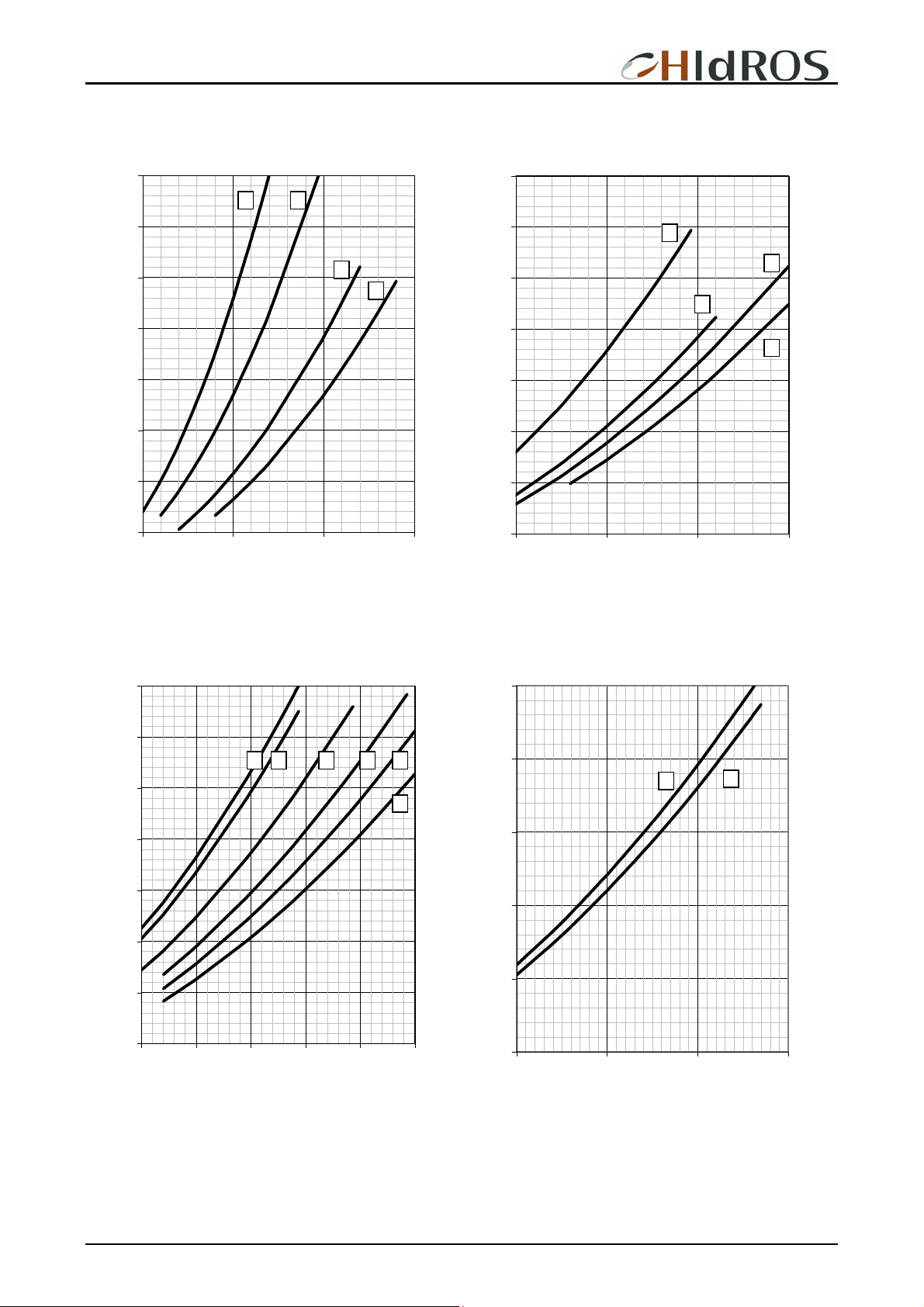
SOURCE SIDE HEAT EXCHANGER WATER PRESSURE DROPS
80
B A
70
60
50
40
30
20
10
5000 10000 15000 20000
A:WDH039-045 B: WDH050
C: WDH 060-070 D: WDH 080
C
D
80
70
60
50
40
30
20
10
15000 20000 25000 30000
E:WDH090 F: WDH110
G: WDH120 H: WDH130
E
G
F
H
80
70
I L M N O
60
P
50
40
30
20
10
25000 30000 35000 40000 45000 50000
I:WDH152-144 L: WDH162-164
M: WDH 190 N: WDH 210
O: WDH240 P: WDH260
60
50
Q
40
30
20
10
40000 50000 60000 70000
Q:WDH300
R: WDH320
R
MTWDHGB REV.072008
20
Page 21
WDH Ground source heat pumps
0
0
A
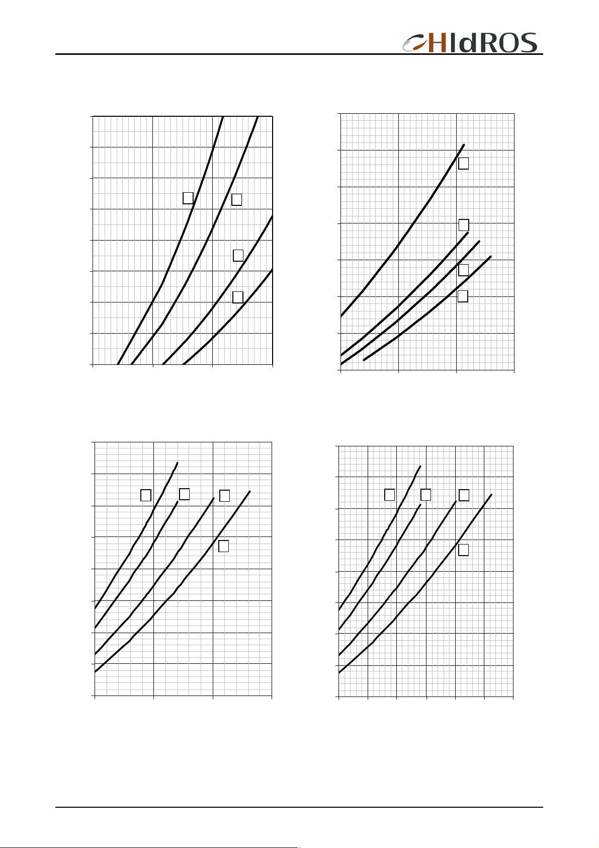
USER SIDE HEAT EXCHANGER WATER PRESSURE DROPS
100
90
90
80
B
70
60
C
50
40
D
30
20
5000 10000 15000 20000
A:WDH039-045 B: WDH050
C: WDH 060-070 D: WDH 080
80
E
70
60
F
50
G
40
H
30
20
20000 25000 30000 3500
E:WDH090 F: WDH110
G: WDH120 H: WDH130
90
I
L
M
80
70
N
60
50
40
30
20
35000 45000 55000 6500
100
90
O P
Q
80
70
R
60
50
40
30
20
35000 40000 45000 50000 55000 60000 65000
I:WDH152-144 L: WDH162-164
M: WDH 190 N: WDH 210
O: WDH240 P: WDH260
Q:WDH300 R: WDH320
MTWDHGB REV.072008
21
Page 22
WDH Ground source heat pumps
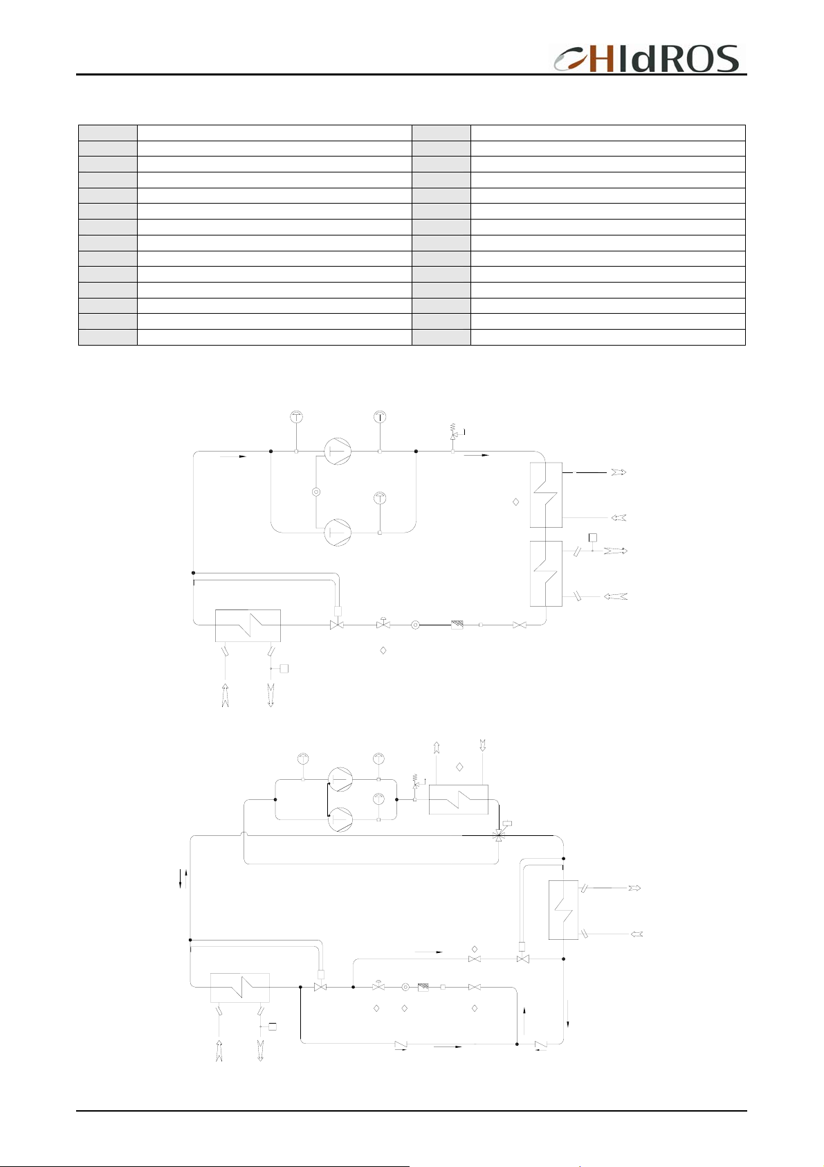
REFRIGERANT LAYOUTS
AAS Domestic hot water feeding SFW Flow switch
BTI Return water sensor SHP High pressure switch
BTO Supply water sensor SLP Low pressure switch
CH Charging plug SV Manual valve
CN User heat exchanger BW Domestic hot water accumulator
CNSW Domestic hot water heat exchanger V3V On/off 3 way valve
DSP Partial heat recovery VR One way valve
EV Source heat exchanger VRV Reverse cycle valve
EXV Thermostatic valve VSH High pressure safety valve
FL Refrigerant filter YBP Hot gas by-pass valve
IV Sight glass YL Liquid line solenoid valve
LR Liquid receiver YW Water solenoid valve
MC Compressor
Option
◊
SFC Free cooling heat exchanger
WDH - STANDARD CONFIGURATION
SLP SHP
VSH
BTI
MC
MC
SHP
YL
DSP
SFW
CND
IV
FL CH SV
BTO
BTI
IO
EV
BTO
EXV
SFW
WDH/RV – REVERSIBLE VERSION
MC
MC
SHP
SHP
VSH
DSP
VRV
NO
NC
SLP
BTO
CND
BTI
EV
BTI
BTO
EXV
SFW
MTWDHGB REV.072008
YL
IV
FL SV
VR
22
SV
CH
EXV
VR
Page 23
WDH Ground source heat pumps
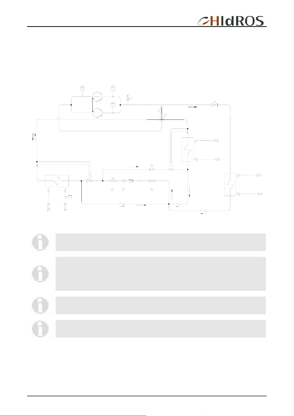
DOMESTIC HOT SANITARY WATER VERSION (WDH/RV/SW6) – 6 WATER PIPE CONNECTIONS
The WDH/SW6 version is suitable to produce cold water, hot water for heating and domestic hot water: the unit is supplied with an
additional heat exchanger used as condenser for the domestic hot water that, is independent from the operation mode of the unit.
The activation of the additional heat exchanger is done automatically by the microprocessor control when the domestic hot water
temperature measured by the sensor is lower than the required set point.
MC
MC
SHP
SHP
VSH
YMI
VRV
NO
NC
CND
YME
BTO
BTI
SLP
BTO
BTI
BTI
EV
EXV
BTO
SFW
YL
IV
FL
VR
CH
SV
SV
EXV
VR
VR
CN
SW
The WDH/RV/SW6 unit, allows the production of cold and hot water, independently from the operation
mode of the unit (heating or cooling).
During winter operation, if domestic hot water is required, it is temporarily stopped the water flow into the
heating system. During summer operation the domestic hot water can be produced at the same time of
the cold water flow.
Domestic hot water is available even when the cooling system is in stand-by or the set point has been
reached.
The unit microprocessor gives always priority to the domestic hot water.
The WDH/RV/SW6 version is only available in the reverse cycle option.
The WDH/RV/SW6 can also be combined with the free cooling version (WDH/FC/RV/SW6).
MTWDHGB REV.072008
23
Page 24
WDH Ground source heat pumps
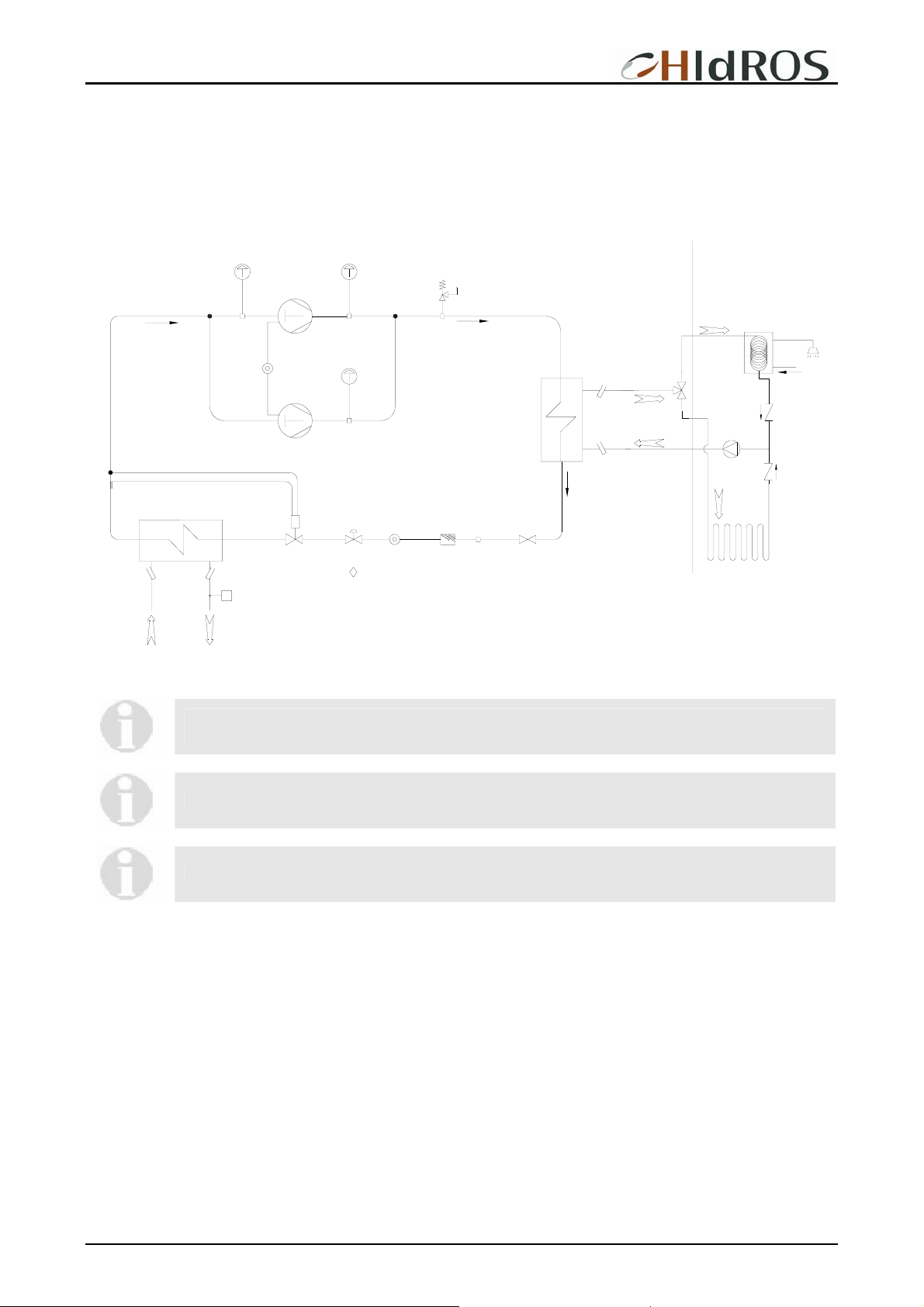
DOMESTIC HOT SANITARY WATER VERSION (WDH/SW5) – 5 WATER PIPE CONNECTIONS
This version is suitable to produce domestic hot water: the unit is supplied with an ON/OFF 3 way valve to deviate the water flow in
a water accumulator; the activation of the 3 way valve is done automatically by the microprocessor control when the domestic hot
water temperature is lower than the required set point.
ØSC ØSS1
BTI
EV
ØSS2
BTO
SLP
MC
IO
MC
EXV
SFW
SHP
SHP
YL
ØDS1
ØDS2
VSH
ØDC
V3W
CND
IV
FL CH SV
BTO
BTI
LIMITE DI FORNITURA
SUPPLY LIMIT
MP
TA
AAS
VR
VR
During winter operation, if domestic hot water is required, it is temporarily stopped the water flow into the
heating system. The unit microprocessor gives always priority to the domestic hot water.
WARNING: The WDH/SW5 is not available in the reversible version (RV).
The WDH/SW5 can also be combined with the free cooling version (WDH/FC/SW5).
MTWDHGB REV.072008
24
Page 25
WDH Ground source heat pumps
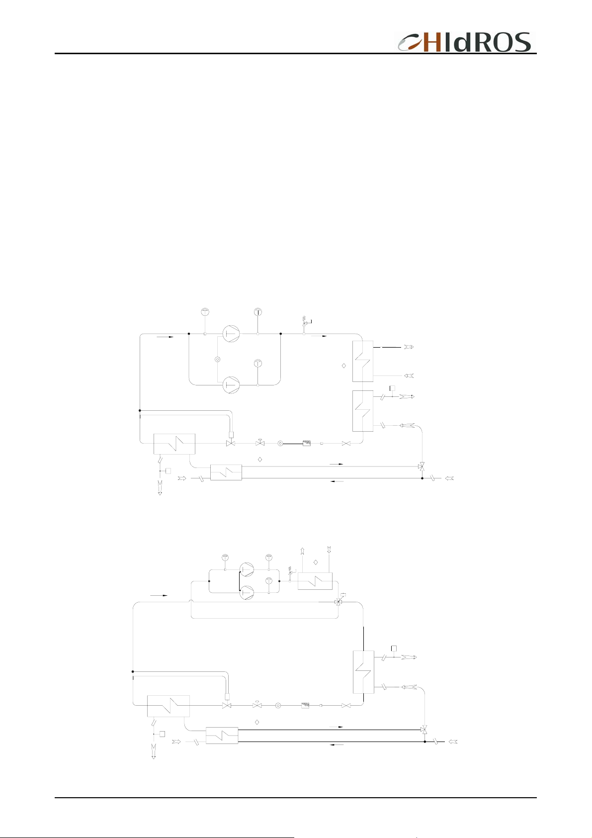
FREE COOLING VERSION WDH/FC
The Free Cooling versions (FC) is suitable for cold water production during summer operation using the cooling capacity coming
from the ground probes.
Operation principle:
The free-cooling heat exchanger is installed in series with the user heat exchanger; the 3 way valve controls the water flow through
the coil. When the ambient temperature is lower than the return water temperature the microprocessor allows the water flow to pass
through the free-cooling coil first, then through the evaporator.
The free cooling versions can operate in 2 different working modes.
Free cooling mode: The ground source probes can grant enough cooling capacity to the system; In this case the 3 way valve opens
the way (A) and the water flow passes into the free cooling heat exchanger coil where the ground probes are sufficient to give the
total required load; the compressors are OFF. In this case, the free cooling system works in substitution of the water chiller.
Free cooling mode + Compressors operation: The ground source probes can NOT grant enough cooling capacity to the system;
In this case the 3 way valve opens the way (A) and the water flow passes into the free cooling heat exchanger coil where it is precooled down to the maximum capacity of the ground probes; then the reverse cycle valve is activated, compressors are switches
ON; and the user water, passing then in the user heat exchanger is cooled down to the required temperature. In this case the free
cooling system works in integration of the water chiller.
SLP
SHP
VSH
MC
MC
EXV
SHP
DSP
SFW
CND
YL
IV
FL CH SV
BTO
BTI
V3W
BTI
BTO
IO
EV
SFW
SFC
BTFC
FREE COOLING VERSION WDH/FC/RV
The WDH/FC/RV performs the same features of the WDH/FC with the possibility of hot water production in winter. Free cooling
operation is stopped when the unit is in heating mode.
SLP SHP
VSH
SHP
MC
MC
DSP
VRV
NO
NC
SFW
BTO
BTI
V3W
BTI
BTO
CND
EV
YL
IV FL CH SV
SFW
BTFC
EXV
SFC
MTWDHGB REV.072008
25
Page 26
WDH Ground source heat pumps
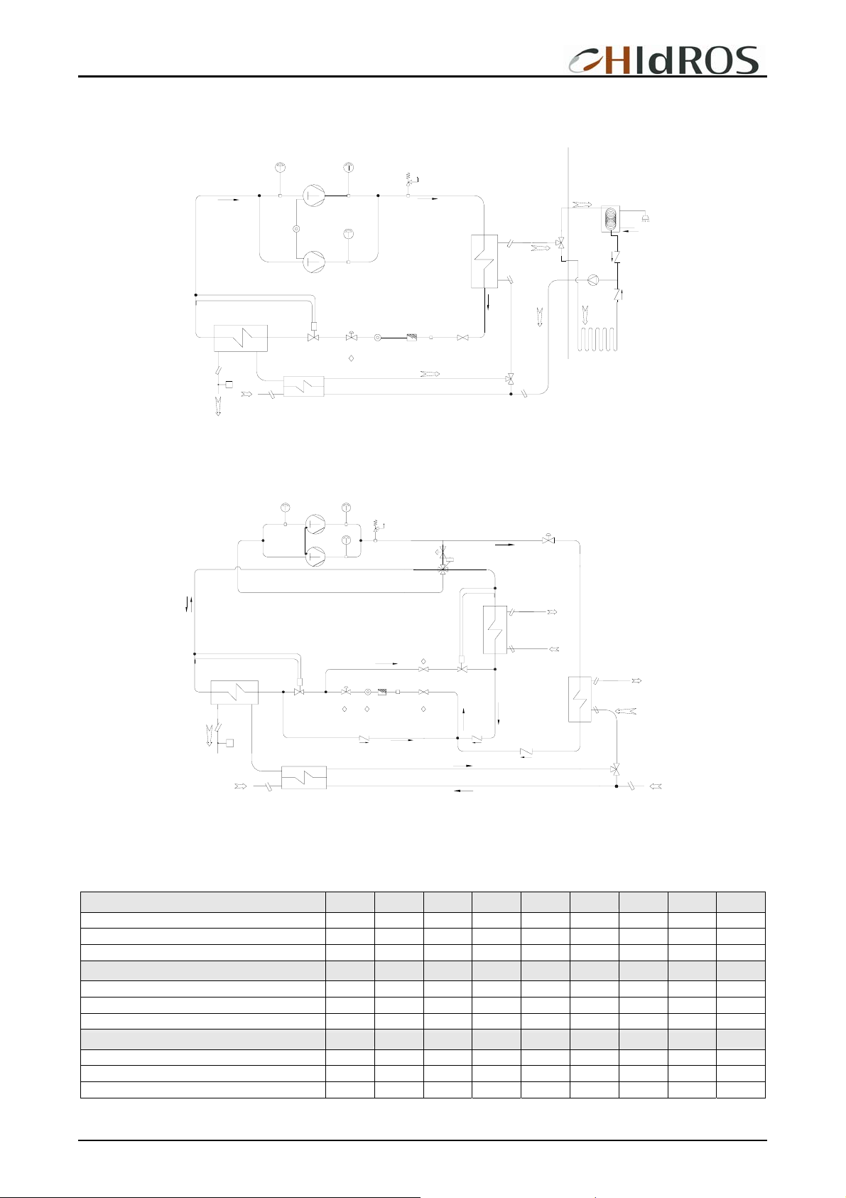
DOMESTIC HOT SANITARY WATER VERSION + FREE COOLING WDH/FC/SW5 – 5 WATER PIPE CONNECTIONS
This unit is able to combined the features of the WDH/SW5 + the FC version;
ØSC ØSS1
EV
BTO
SFW
ØSS2
BTFC
SLP
IO
SFC
MC
MC
EXV
SHP
SHP
VSH
ØDS1
ØDS2
YL
IV
ØDC
CND
FL CH SV
BTO
TA
V3W
BTI
LIMITE DI FORNITURA
SUPPLY LIMIT
V3W
BTI
AAS
VR
MP
VR
DOMESTIC HOT SANITARY WATER VERSION + FREE COOLING WDH/FC/RV/SW6( 6 WATER PIPE CONNECTIONS)
This unit is able to combined the features of the WDH/RV/SW6 + the FC version;
SLP
SHP
VSH
SHP
MC
MC
YMI
VRV
NO
NC
YME
BTO
CND
BTI
BTO
BTI
V3W
BTI
BTO
EV
SFW
BTFC
EXV
SFC
YL
IV
VR
CH
FL SV
SV
EXV
CN
SW
VR
VR
FREE COOLING VERSION CAPACITIES (FC)
The nominal Free Cooling capacity is obtained when all compressors are OFF, the ground source water inlet temperature is 10°C,
the user return water temperature is 20°C and the nominal water flow (for each model) is the one reported in the table.
Mod. 039 045 050 060 070 080 090 110
Free cooling nominal capacity kW 24 28 33 37 41 50 58 66
Water consumption l/h 6680 8140 9460 10530 11650 14170 16500 18850
Water pressure drops kPa 34 44 38 45 52 33 44 56
Mod. 120 130 152 162 144 164 190 210
Free cooling nominal capacity kW 74 83 92 102 90 99 115 162
Water consumption l/h 21230 23640 26500 29400 25800 28400 33000 130
Water pressure drops kPa 48 56 42 55 39 51 55 34
Mod. 240 260 300 320
Free cooling nominal capacity kW 148 165 184 204
Water consumption l/h 42500 47300 53000 58700
Water pressure drops kPa 42 46 44 56
MTWDHGB REV.072008
26
Page 27
WDH Ground source heat pumps
PARTIAL HEAT RECOVERY CAPACITY (OPTION)
Mod. 039 045 050 060 070 080 090 110
Partial heat recovery nominal capacity kW 9,5 12,8 13,0 15,0 15,3 18,5 21,5 24,8
Water flow l/h 1635 2200 2240 2580 2630 3190 3700 4270
Water pressure drops kPa 10 14 11 15 16 18 11 15
Mod. 120 130 140 160 190 210 240 260
Partial heat recovery nominal capacity kW 27,5 30,0 34,0 37,0 43,0 49,0 55,0 61,5
Water flow l/h 4730 5160 5850 6360 7400 8430 9460 10570
Water pressure drops kPa 13 18 18 25 11 15 19 25
Mod. 300 320
Partial heat recovery nominal capacity kW 69,0 76,0
Water flow l/h 11850 13000
Water pressure drops kPa 20 25
The nominal value refers to an source water temperature 10/5°C and user outlet water temperature 50°C (Dt 5°C).
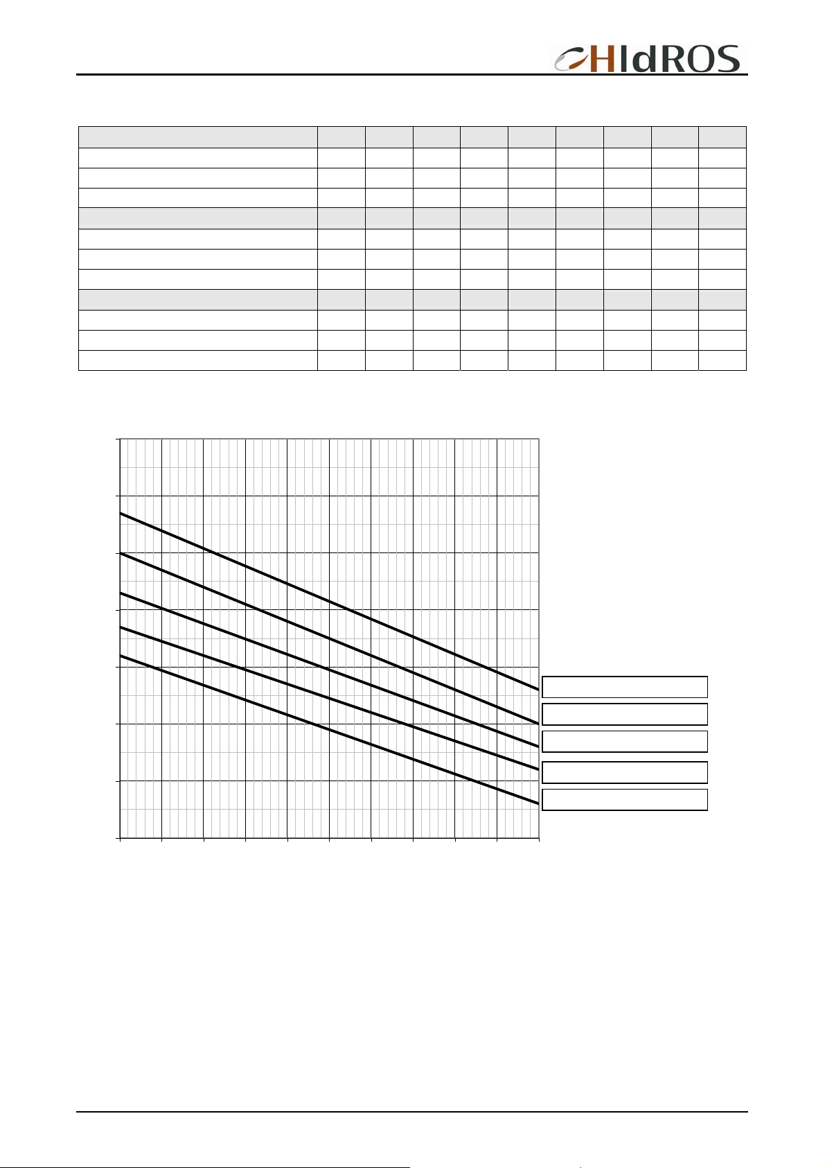
1,5
1,4
1,3
1,2
1,1
Source water temperature 15°C
1
0,9
0,8
40 41 42 43 44 45 46 47 48 49 50
Outlet water temperature °C
Source water temperature 10°C
Source water temperature 5°C
Source water temperature 0°C
Source water temperature -5°C
The heat recovery capacity in different conditions can be obtained multiplying the nominal capacity (See above), by the correction
factor indicated in the table.
MTWDHGB REV.072008
27
Page 28
WDH Ground source heat pumps
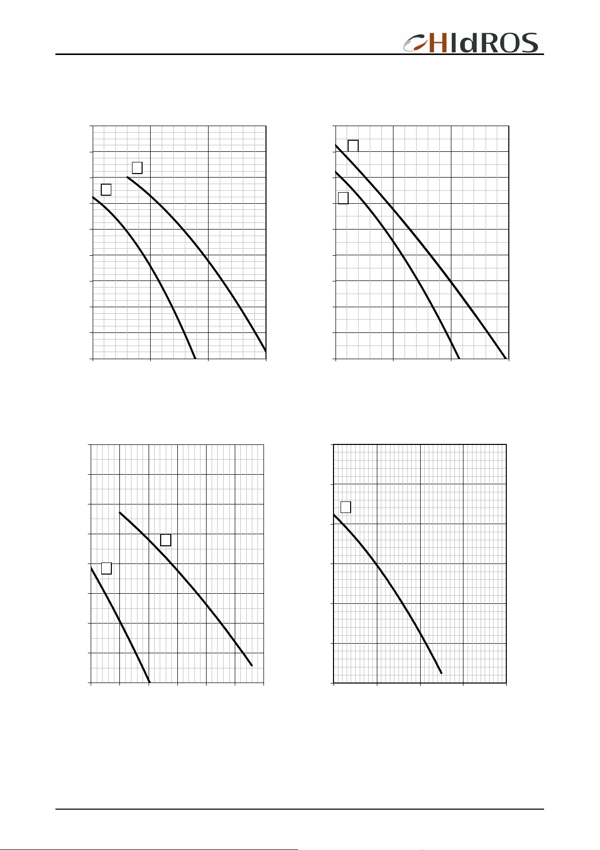
WATER PUMPS AVAILABLE STATIC PRESSURE (OPTION)
240
220
B
200
A
180
160
140
120
100
80
60
5000 10000 15000 20000
A: WDH039,045,050,060,070
B: WDH080, 090
220
200
180
160
140
120
100
D
C
80
60
40
15000 20000 25000 30000
C: WDH110, 120
D: WDH130
240
220
200
180
160
140
120
100
E
80
30000 35000 40000 45000 50000 55000 60000
E: WDH 152,144, 162,164,190
F: WDH 210, 240, 260
F
220
200
G
180
160
140
120
100
50000 60000 70000 80000 90000
G: WDH300, 320
MTWDHGB REV.072008
28
Page 29
WDH Ground source heat pumps
60
50
40
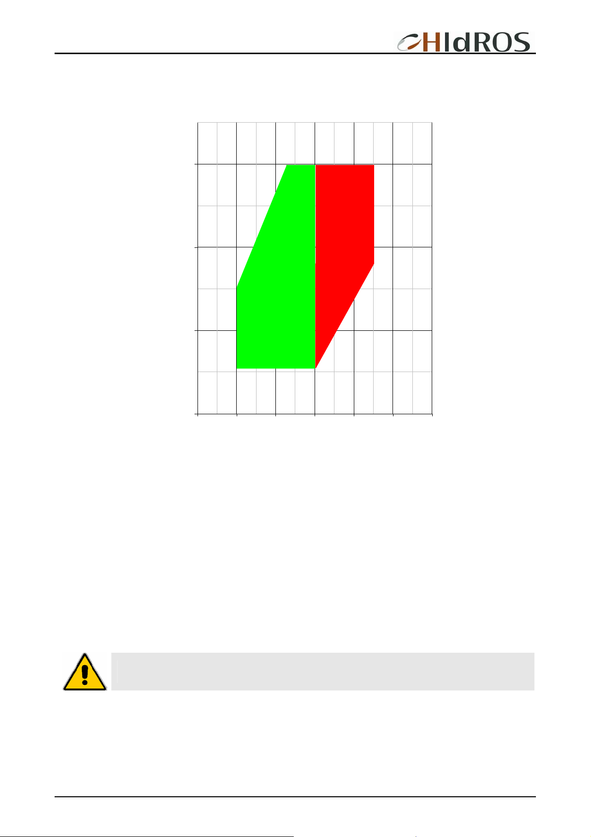
User Outlet water temperature (°C)
OPERATION LIMITS
Contact
technical
department
Standard
versions
30
-10 0 10 20 30 40 50
Source circuit inlet water temperature (°C)
Source circuit water flow rate
The nominal water flow rate given by HIDROS is referred to a Dt of 5 °C. Maximum flow rate allowed is the one that presents a Dt of
3°C: higher values may cause too high pressure drop. The minimum water flow rate allowed is the one presenting a Dt of 8 °C.
Insufficient values cause too low evaporating temperatures with the action of safety devices which would stop the unit.
User heat exchanger water temperature
Once the system is on temperature, water temperature at the user heat exchanger inlet does not have to be less than 30°C: lower
values could cause incorrect working operation of the compressor and compressor failure may occur. The maximum water outlet
temperature at the user heat exchanger is 58°C.
Source heat exchanger water temperature
The minimum evaporator water outlet temperature is 7°C. To operates below this limit a glycol mixture must be used. In case of
glycol use the minimum evaporator water outlet is -5°C. The maximum evaporator water outlet is 20°C. In case of operation outside
this range of temperatures please contact the company.
WARNING: In case of operation outside this range of temperatures please contact our technical
department.
MTWDHGB REV.072008
29
Page 30
WDH Ground source heat pumps
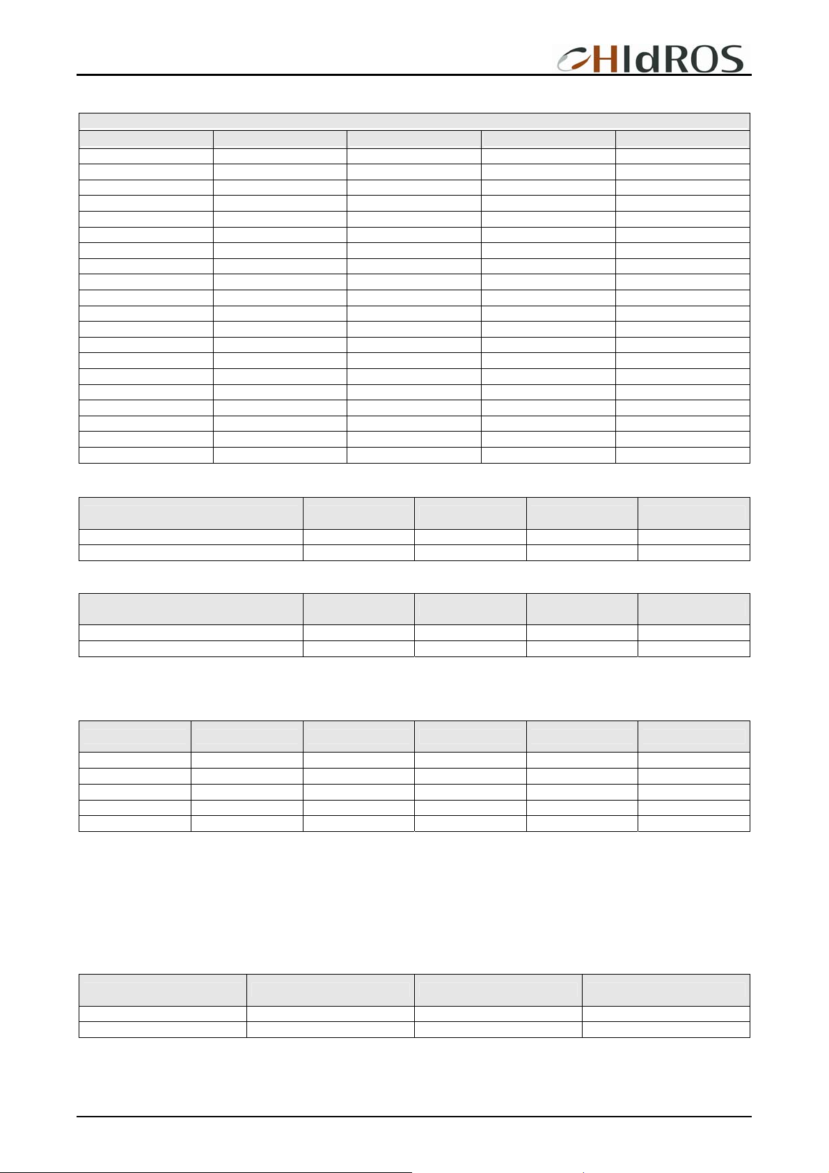
Model 1 2 3 4
039 50% 50% --- ---
045 50% 50% --- ---
050 50% 50% --- ---
060 44% 56% --- ---
070 50% 50% --- ---
080 50% 50% --- ---
090 43% 57% --- ---
110 50% 50% --- ---
120 45% 55% --- ---
130 50% 50% --- ---
152 44% 56% --- ---
162 50% 50% --- ---
144 21,5% 21,5% 28,5% 28,5%
164 25% 25% 25% 25%
190 21,5% 21,5% 28,5% 28,5%
210 25% 25% 25% 25%
240 22,5% 22,5% 27,5% 27,5%
260 25% 25% 25% 25%
300 22% 22% 28% 28%
320 25% 25% 25% 25%
CORRECTION TABLES Source side heat exchanger temperature difference °C
COMPRESSORS CAPACITY STEP CONTROLS
COMPRESSORS NUMBER
Fouling factor 3 5 8 10
HCCCP 1,02 1 0,98 0,97
IPCF 1,01 1 0,99 0,98
CORRECTION TABLES User side heat exchanger temperature difference °C
Fouling factor 3 5 8 10
HCCCP 0,99 1 1,01 1,015
IPCF 1,01 1 0,99 0,99
HCCF = Heating capacity correction factor. IPCF = Input power correction factor.
The correction factors have to be applied to the nominal data reported in the previous tables that shows the capacitieswith Dt5°C.
CORRECTION TABLES Operation with glycol
Glicol percentage Freezing point (°C) CCF IPCF WFCF PDCF
10 -3,2 0,985 1 1,02 1,08
20 -7,8 0,98 0,99 1,05 1,12
30 -14,1 0,97 0,98 1,09 1,22
40 -22,3 0,965 0,97 1,14 1,25
50 -33,8 0,955 0,965 1,2 1,33
CCF: Capacity correction factor IPCF: Input power correction factor
WFCF: Water flow correction factor PDCF: Pressure drops correction factor.
The water flow rate and pressure drop correction factors are to be applied directly to the values given for operation without glycol.
The water flow rate correction factor is calculated in order to maintain the same temperature difference as that which would be
obtained without glycol. The pressure drop correction factor takes into account the different flow rate obtained from the application of
the flow rate correction factor.
CORRECTION TABLES Different Fouling factors
Fouling factor 0,00005 0,0001 0,0002
CCCP 1 0,98 0,94
IPCF 1 0,98 0,95
CCF = Cooling capacity correction factor. IPCF = Input power correction factor.
MTWDHGB REV.072008
30
Page 31
WDH Ground source heat pumps
Mod.
039
045
050
060
070
080
090
110
120
130
152
162
144
164
190
210
240
260
300
320
63 125 250 500 1K 2K 4K 8K
dB dB dB dB dB dB dB dB
93,1 84,3 78,2 76,7 75,6 70,2 66,8 57,7 93,9 80 52
93,1 84,3 78,2 76,7 75,6 70,2 66,8 57,7 93,9 80 52
94,1 85,3 79,2 77,7 76,6 71,2 67,8 58,7 94,9 81 53
95,1 86,3 80,2 78,7 77,6 72,2 68,8 59,7 95,9 82 54
95,1 86,3 80,2 78,7 77,6 72,2 68,8 59,7 95,9 82 54
96,1 87,3 81,2 79,7 78,6 73,2 69,8 60,7 96,9 83 55
96,1 87,3 81,2 79,7 78,6 73,2 69,8 60,7 96,9 83 55
97,1 88,3 82,2 80,7 79,6 74,2 70,8 61,7 97,9 84 56
97,1 88,3 82,2 80,7 79,6 74,2 70,8 61,7 97,9 84 56
98,1 89,3 83,2 81,7 80,6 75,2 71,8 62,7 98,9 85 57
98,1 89,3 83,2 81,7 80,6 75,2 71,8 62,7 98,9 85 57
98,1 89,3 83,2 81,7 80,6 75,2 71,8 62,7 98,9 85 57
98,1 89,3 83,2 81,7 80,6 75,2 71,8 62,7 98,9 85 57
98,1 89,3 83,2 81,7 80,6 75,2 71,8 62,7 98,9 85 57
99,1 90,3 84,2 82,7 81,6 76,2 72,8 63,7 99,9 86 58
101,1 92,3 86,2 84,7 83,6 78,2 74,8 65,7 101,9 88 60
101,1 92,3 86,2 84,7 83,6 78,2 74,8 65,7 101,9 88 60
101,1 92,3 86,2 84,7 83,6 78,2 74,8 65,7 101,9 88 60
103,1 94,3 88,2 86,7 85,6 80,2 76,8 67,7 103,9 90 62
103,1 94,3 88,2 86,7 85,6 80,2 76,8 67,7 103,9 90 62
SOUND DATA
SOUND LEVELS STANDARD VERSIONS
Octave bands (Hz) Lw Lp
dB dB(A) dB(A)
SOUND LEVELS (LS) LOW NOISE VERSIONS
Octave bands (Hz) Lw Lp
Mod.
039/LS
045/LS
050/LS
060/LS
070/LS
080/LS
090/LS
110/LS
120/LS
130/LS
152/LS
162/LS
144/LS
164/LS
190/LS
210/LS
240/LS
260/LS
300/LS
320/LS
Lw: Sound power level according to ISO 3746.
Lp: Sound pressure level measured at 10 mt from the unit in free field conditions direction factor Q=2 according to ISO 3746.
63 125 250 500 1K 2K 4K 8K
dB dB dB dB dB dB dB dB
87,1 78,3 72,2 70,7 69,6 64,2 60,8 51,7 87,9 74 46
87,1 78,3 72,2 70,7 69,6 64,2 60,8 51,7 87,9 74 46
88,1 79,3 73,2 71,7 70,6 65,2 61,8 52,7 88,9 75 47
89,1 80,3 74,2 72,7 71,6 66,2 62,8 53,7 89,9 76 48
89,1 80,3 74,2 72,7 71,6 66,2 62,8 53,7 89,9 76 48
90,1 81,3 75,2 73,7 72,6 67,2 63,8 54,7 90,9 77 49
90,1 81,3 75,2 73,7 72,6 67,2 63,8 54,7 90,9 77 49
91,1 82,3 76,2 74,7 73,6 68,2 64,8 55,7 91,9 78 50
91,1 82,3 76,2 74,7 73,6 68,2 64,8 55,7 91,9 78 50
92,1 83,3 77,2 75,7 74,6 69,2 65,8 56,7 92,9 79 51
92,1 83,3 77,2 75,7 74,6 69,2 65,8 56,7 92,9 79 51
92,1 83,3 77,2 75,7 74,6 69,2 65,8 56,7 92,9 79 51
92,1 83,3 77,2 75,7 74,6 69,2 65,8 56,7 92,9 79 51
92,1 83,3 77,2 75,7 74,6 69,2 65,8 56,7 92,9 79 51
93,1 84,3 78,2 76,7 75,6 70,2 66,8 57,7 93,9 80 52
95,1 86,3 80,2 78,7 77,6 72,2 68,8 59,7 95,9 82 54
95,1 86,3 80,2 78,7 77,6 72,2 68,8 59,7 95,9 82 54
95,1 86,3 80,2 78,7 77,6 72,2 68,8 59,7 95,9 82 54
97,1 88,3 82,2 80,7 79,6 74,2 70,8 61,7 97,9 84 56
97,1 88,3 82,2 80,7 79,6 74,2 70,8 61,7 97,9 84 56
dB dB(A) dB(A)
MTWDHGB REV.072008
31
Page 32
WDH Ground source heat pumps
SAFETY DEVICE SETTING
Device
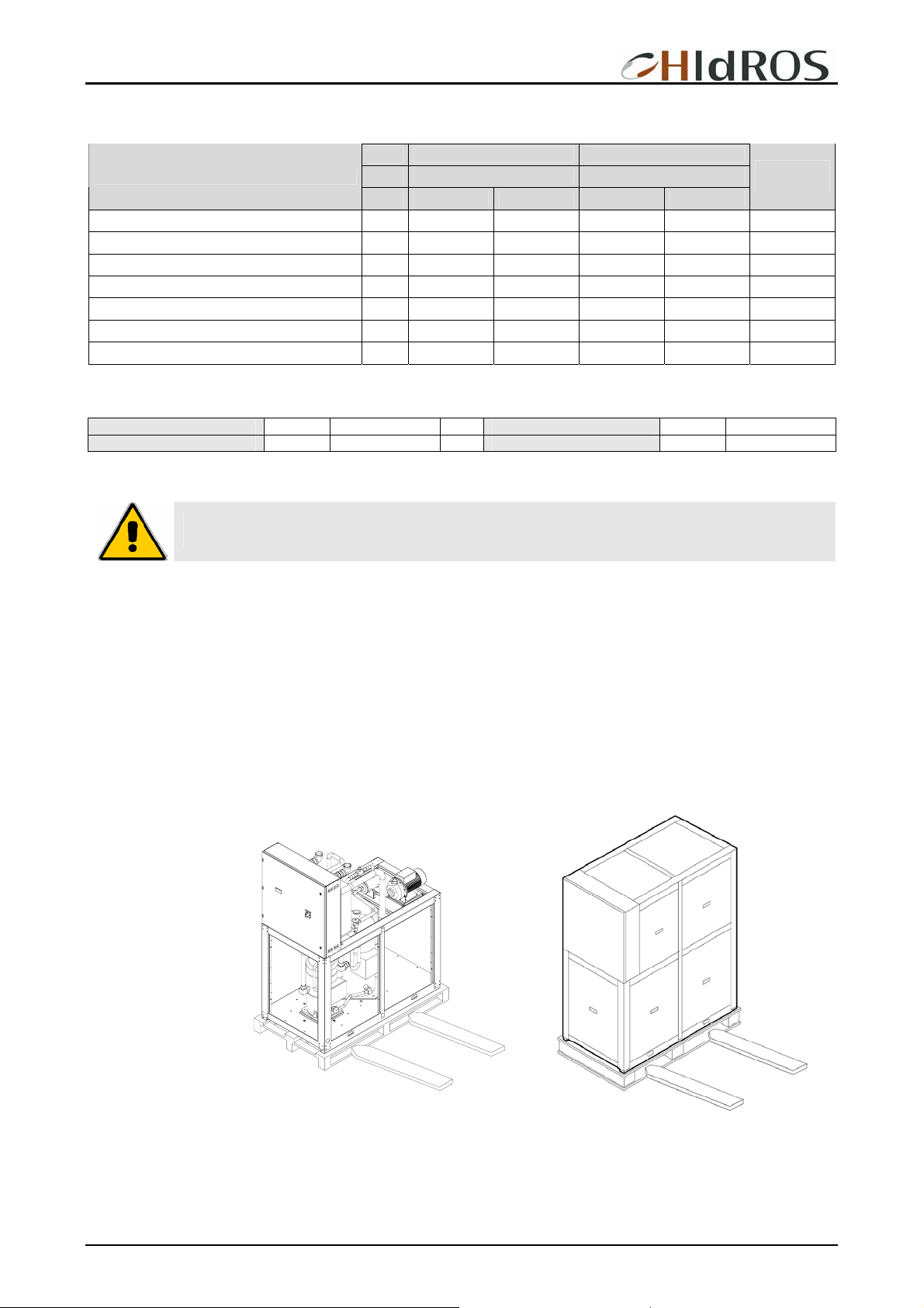
Control thermostat (summer) °C 10 2 9 3 …
Control thermostat (winter) °C 42 2 43 3 …
Anti-freeze thermostat °C 4 6 4 6 MANUAL
Electric heater thermostat °C 4 6 4 6 MANUAL
High pressure switch Bar 28 7 28 7 MANUAL
Low pressure switch Bar 0,7 1 0,7 1 MANUAL
Water safety valve (Optional) Bar 6 … 6 … …
Capacity Steps Capacity steps
2 4
Set-point Differential Set point Differential
Reset
Type
ELECTRIC DATA
Power supply V/~/Hz 400 / 3 / 50 Control board V/~/Hz 24 / 1 / 50
Auxiliary circuit V/~/Hz 230 / 1 / 50
Electric data may change for updating. It is therefore necessary to refer always to the wiring diagram inside the units.
WARNING: All this operation described in next chapters MUST BE DONE BY TRAINED PEOPLE ONLY.
Before every operation of servicing on the unit, be sure that the electric supply is disconnected.
INSPECTION
When installing or servicing the unit, it is necessary to strictly follow the rules reported on this manual, to conform to all the
specifications of the labels on the unit, and to take any possible precautions of the case. Not observing the rules reported on this
manual can create dangerous situations. After receiving the unit, immediately check its integrity. The unit left the factory in perfect
condition; any eventual damage must be questioned to the carrier and recorded on the Delivery Note before it is signed. HIDROS
must be informed, within 8 days, of the extent of the damage. The Customer should prepare a written statement of any severe
damage.
LIFTING AND HANDLING
Standard version Low noise version
When unloading the
unit, it is highly
recommended to avoid
any sudden move in
order to protect
refrigerant circuit,
copper tubes or any
other unit component.
Units can be lifted by
using a forklift or, in
alternative, using belts,
being sure that the
method of lifting does
not damage the lateral
panels and the cover. It
is important to keep the
unit horizontal at all
time to avoid damages
to the internal
components.
MTWDHGB REV.072008
32
Page 33
WDH Ground source heat pumps
LOCATION AND MINIMUM TECHNICAL CLEARANCES
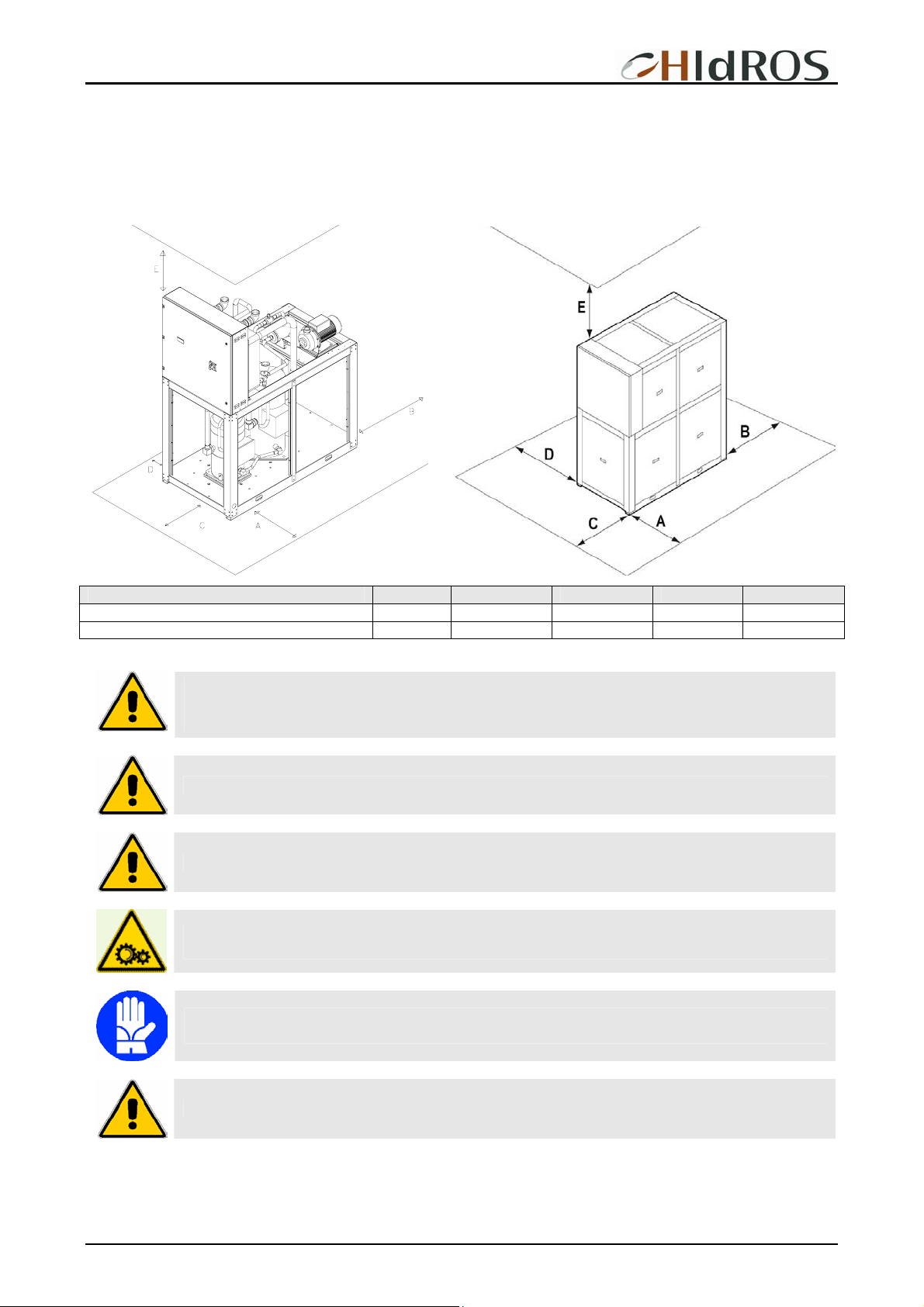
WDH units are designed for indoor installation. It is advisable to create a proper basement, with a size similar to unit foot-print. Unit
vibration level is very low: it is advisable however, to fit a rigid rubber band between basement and unit base-frame. If it is the case, it
is possible to install anti-vibration mounts (spring or rubber), to keep vibrations at a very low level. It is also necessary to observe the
following clearances for service and maintenance:
Standard version Low noise version
Mod. A B C D E
039-045 -050–060–070-080-090–110–120–130 1000 500 600 0 500
144-164-190-210-240-260-300-320-380-430-500 1000 500 800 0 500
WARNING: The equipment should be installed so that maintenance and/or repair services be possible.
The warranty does not cover costs due to lifting apparatus and platforms or other lifting systems
required by the warranty interventions.
WARNING: All the maintenance operation must be done by TRAINED PEOPLE only.
WARNING: Before any service operation on the unit, be sure that the electric supply is disconnected.
WARNING: Inside the unit some moving components are present. Be very careful when operating in their
surroundings even if the electric supply is disconnected.
WARNING: The top shell and discharge line of compressor are usually at high temperature level. Be very
careful when operating in their surroundings.
WARNING: After servicing operation close the unit with cover panels, fixing them with locking screws
MTWDHGB REV.072008
33
Page 34
WDH Ground source heat pumps
HYDRAULIC CIRCUIT
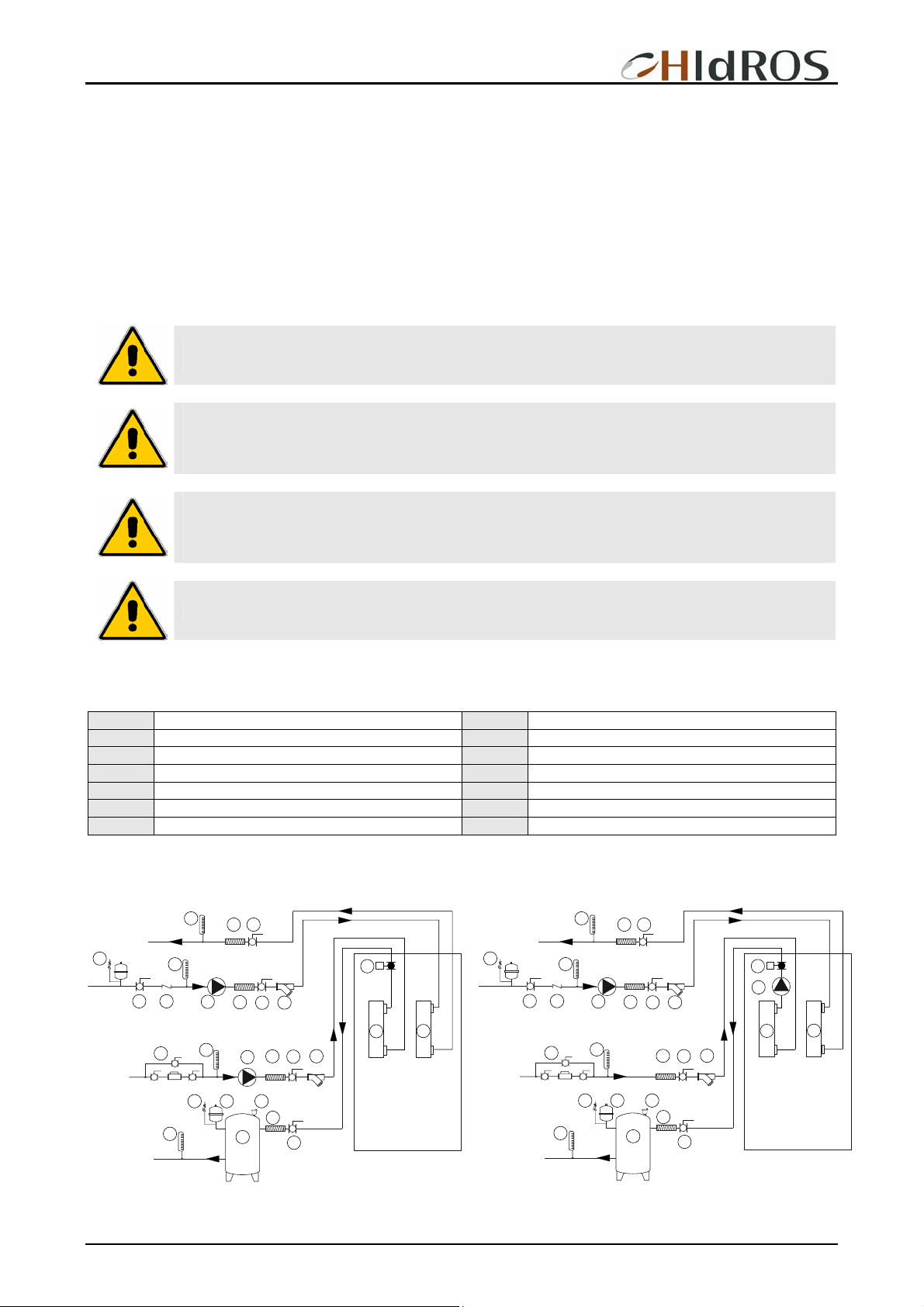
Unit water pipe-work must be installed in accordance with national and local regulation, pipes can be made either in steel ,
galvanized steel or PVC. Pipes have to be designed depending on the nominal waterflow and the hydraulic pressure drops of the
system. All pipes must be insulated with closed-cell material of adequate thickness. The unit has to be connected to the piping by
using flexible joints. Piping should include:
• Temperature and pressure gauges for the ordinary maintenance or servicing operations.
• Shut-off manual valves to separate the unit from the hydraulic circuit.
• Metallic filters to be mounted on the inlet pipe with a mesh not larger than 1 mm.
• Vent valves, expansion tank with water filling, discharge valve.
The installation of the following accessories is also recommended: Water tank for economic operation and constant user water
temperature (P); Hydraulic circuit manual shut-off valves (D); Air separator with safety valve (H); Aautomatic system feeder with
pressure gauge (A);
WARNING: Unit water inlet must be in correspondence with the connection labelled: ”USER WATER IN”,
otherwise the heat exchangers may freeze.
WARNING: It is compulsory to install on the heat exchangers water inlet connections a metallic filter with
a mesh not larger than 1 mm. THE FILTER IS MANDATORY, the warranty will no longer be valid if it is not
present or removed. The filter must be kept clean, so make sure it is clean after the unit has been
installed, and then check it periodically.
WARNING: All units are factory supplied with the user heat exchanger flow switch. The flow switch MUST
BE INSTALLED on the water outlet connection (labelled USER WATER OUT); If the flow switch is altered,
removed, or the water filter should not be present on the unit, the warranty will be invalidated. Please refer
to the wiring diagram for flow switch electric connections.
WARNING: Water flow in the user heat exchanger MUST BE CONSTANT.
In the following picture there is a layout of the WDH hydraulic circuit to show the suggested devices.
LEGEND
A System filling group H Vent valve
Thermometer
B
C Flexible connection N
D Ball shut-off valve O
L Water pump
User heat exchanger
Flow switch
E Water strainer P Water tank
F Expansion vessel Q Source heat exchanger
G Safety valve
WDH WDH A1NT
B
C
D
G
B
M
D
A
L
C
E
D
B
L
E
C
D
O
Q
N
G
D
B
C
D
B
M
L
C
B
A
O
E
D
E
C
D
L
N
Q
G F H
B
C
P
D
G F H
B
C
P
D
MTWDHGB REV.072008
34
Page 35
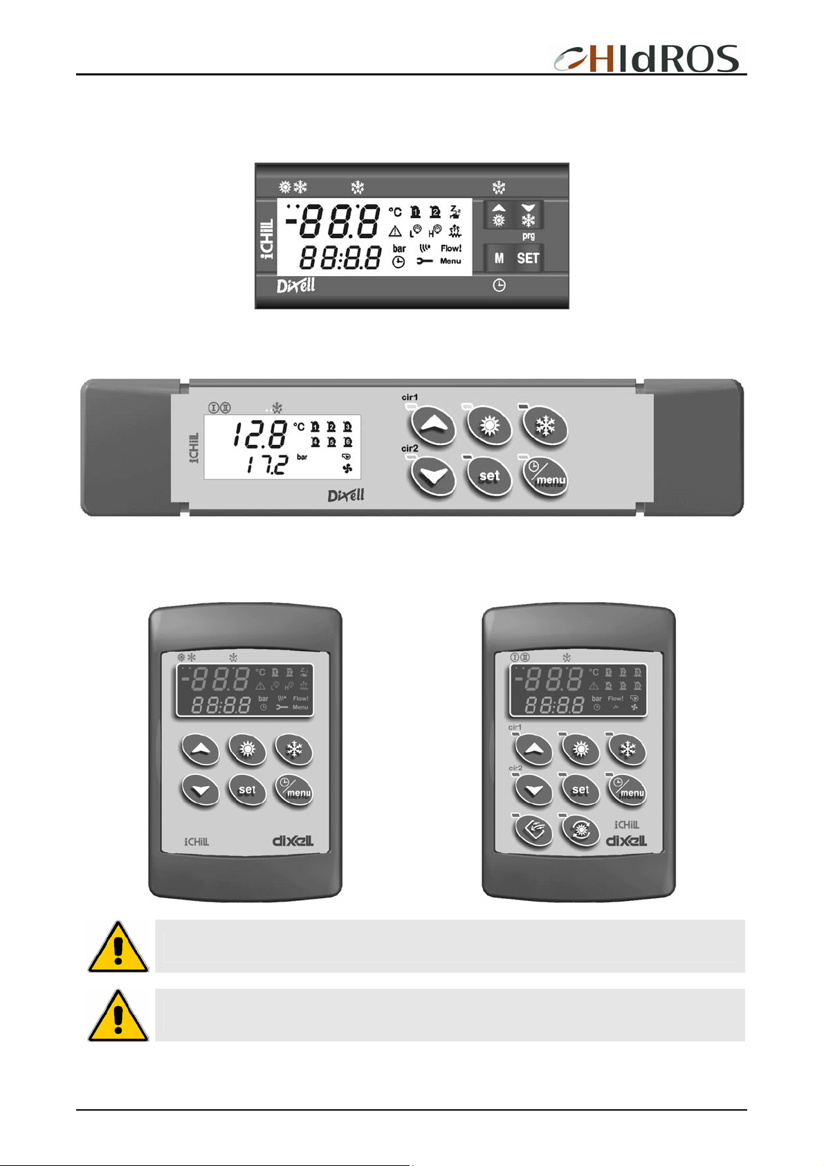
WDH Ground source heat pumps
UNIT DISPLAY
MODELS 039÷162
MODELS 144 ÷320
REMOTE CONTROL PANEL
MODELS 039÷162
Dimensions : 100 x 64 mm
MODELS 144 ÷320
Dimensions: 100 x 64 mm
WARNING: The remote control panel is connected to the water chiller by 2 wires of 2,5 mm2 section. Power
supply cables must be separated by remote control wires. Maximum distance 50 metres.
WARNING: The remote control panel can not be installed in area in with strong vibrations, corrosive gases,
excess of dirtness or high humidity level. Leave free the area near the cooling openings.
MTWDHGB REV.072008
35
Page 36

WDH Ground source heat pumps
ELECTRICAL CONNECTIONS
It must be verified that electric supply is corresponding to the unit electric nominal data (tension, phases, frequency) reported on the
label in the front panel of the unit. Power connections must be made in accordance to the wiring diagram enclosed with the unit and
in accordance to the norms in force. Power cable and line protection must be sized according to the specification reported on the
form of the wiring diagram enclosed with the unit.
WARNING: The line voltage fluctuations can not be more than ±5% of the nominal value, while the voltage
unbalance between one phase and another can not exceed 2%. If those tolerances should not be
respected, please contact our Company.
WARNING: Electric supply must be in the limits shown: in the opposite case warranty will terminate
immediately. Before every operation on the electric section, be sure that the electric supply is
disconnected.
WARNING: The Flow switch must be connected following the indication reported in the wiring diagram.
Never bridge the flow switch connections in the terminal board. Guarantee will be invalidated if flow
switch connections are altered or not properly made.
START UP
Before start-up
• Check that all power cables are properly connected and all terminals are hardly fixed.
• The voltage at the phase R S T is the one shown in the unit labels.
• Check that there is not any refrigerant leakage.
• Check that crankcase heaters are powered correctly.
• Check that all water connections are properly installed and all indications on unit labels are observed.
• The system must be bleed off in order to eliminate any air.
• Before proceeding to start up check that all the cover panels are re-located in the proper position and locked with fastening
screws.
WARNING: Crankcase heaters must be powered at least 12 hours before start up by closing the main
switch (heaters are automatically supplied when main switch is closed). The crankcase heaters are
working properly if after some minutes the compressor crankcase temperature is about 10÷15°C higher
than ambient temperature
Start up
Please refer to the microprocessor manual enclosed with the unit.
If the unit should not start:
• Check that the control thermostat is set to the correct value.
WARNING: Do not modify internal wiring of the unit otherwise warranty will terminate immediately.
WARNING: In the reverse cycle versions, the summer/winter operation must be selected at the beginning
of the related season. Frequent change over of the seasonal operation mode must be avoided in order to
prevent severe damage to compressors.
MTWDHGB REV.072008
36
Page 37

WDH Ground source heat pumps
Refrigerant charge checking
• After few hours the unit is working, check that sight glass shows a green colour core: if the core is yellow moisture would be
present in the circuit. In this case it is necessary circuit dehydration to be carried out by qualified people only. Check that at the sight
glass there is no continuous vapour bubbles presence. In this case additional refrigerant charge could be required. It is however
allowed the presence of few vapour bubbles.
• Check that refrigerant superheat on the evaporator is about 5-7 °C
• Check if refrigerant sub-cooling on the condenser is about 5-7 °C.
Unit switch OFF
Please refer to the microprocessor manual enclosed with the unit.
WARNING: Never switch off the unit (for temporary stop), by opening the main switch: this component
should be used only to disconnect the unit from power supply when the current is not passing through,
i.e. when the unit is in OFF mode. Moreover, with no supply to crankcase heater, at the unit start up,
compressor could be seriously damaged.
MAINTENANCE AND PERIODIC CHECKS
WARNING: All operations described in this chapter MUST BE DONE BY TRAINED PEOPLE ONLY. Before
every operation of servicing on the unit, be sure that the electric supply is disconnected. The top shell
and discharge line of compressor are usually at high temperature level. Be very careful when operating in
their surroundings. Aluminium coil fins are very sharp and can cause serious wounds. Be very careful
when operating in their surroundings. After servicing operation close the unit with cover panels, fixing
them with locking screws.
It is a good rule to carry on periodic checks in order to verify the correct operation of the unit.
• Check that safety and control devices work correctly as previously described (monthly).
• Check all the terminals on the electric board and on the compressor are properly fixed. Periodic cleaning of the sliding terminals
of the contactors should be done.
• Verify refrigerant charge checking sight glass (monthly).
• Check there is no oil leakage from compressor (monthly).
• Check there is no water leakage in the hydraulic system (monthly).
• If the unit is to be expected to be stopped for a long period, unit hydraulic circuit should be emptied from all the tubes and heat
exchanger. This operation is compulsory if, during seasonal stop, ambient temperature is expected to go down below the freezing
point of employed mixture (typical seasonal operation).
• Check flow switch proper working (monthly).
• Check compressor crankcase heater proper supply and functioning (monthly).
• Clean metallic filters on water pipings (monthly).
• Check the colour of the sight glass core (green=no moisture, yellow=moisture present): if it has a yellow colour, change the
refrigerant filter (every 4 months).
MTWDHGB REV.072008
37
Page 38

WDH Ground source heat pumps
REFRIGERANT CIRCUIT REPAIR
In the case that refrigerant circuit should be discharged, all the refrigerant must be recovered with proper machines. The
system must be charged with nitrogen, using a gas bottle with a pressure reducing valve, until 15 bar pressure is reached. Any
eventual leakage must be searched with a bubble leak finder. In case bubbles appear discharge the circuit before welding with
proper alloys.
WARNING: Never use oxygen instead of nitrogen: explosions may occur.
ENVIRONMENT PROTECTION
According to European norms dealing with the use of depleting stratospheric ozone substances, it is forbidden to release
refrigerants fluids in the atmosphere. They must be redelivered to the seller or to proper gathering points at the end of their
operating life. Refrigerant R407C is mentioned among controlled substances and for this reason it must be subjected to said norms.
A particular care is recommended during service operations in order to reduce as much as possible any refrigerant loss
.
UNIT OUT OF SERVICE
Once the unit is arrived at the end of its life and needs to be removed or replaced, the following operations are recommended:
• the unit refrigerant has to be recovered by trained people and sent to proper collecting centre;
• compressor lubricating oil has to be recovered and sent to proper collecting centre;
• the frame and various components, if not usable any longer, have to be dismantled and divided according to their nature;
particularly copper and aluminium, which are present in conspicuous quantity in the unit. These operations allow easy material
recover and recycling process, reducing environmental impact.
FAULT FINDING
Please refer to the unit microprocessor manual.
MTWDHGB REV.072008
38
Page 39
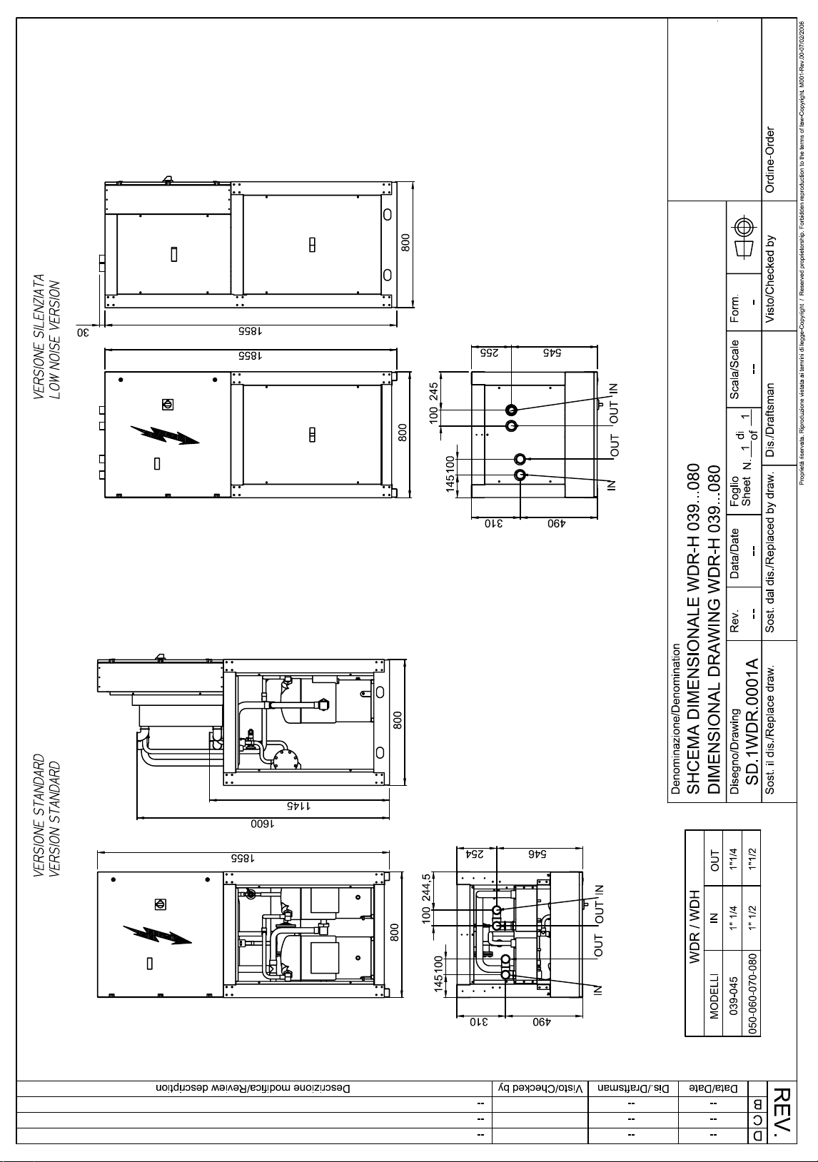
Page 40
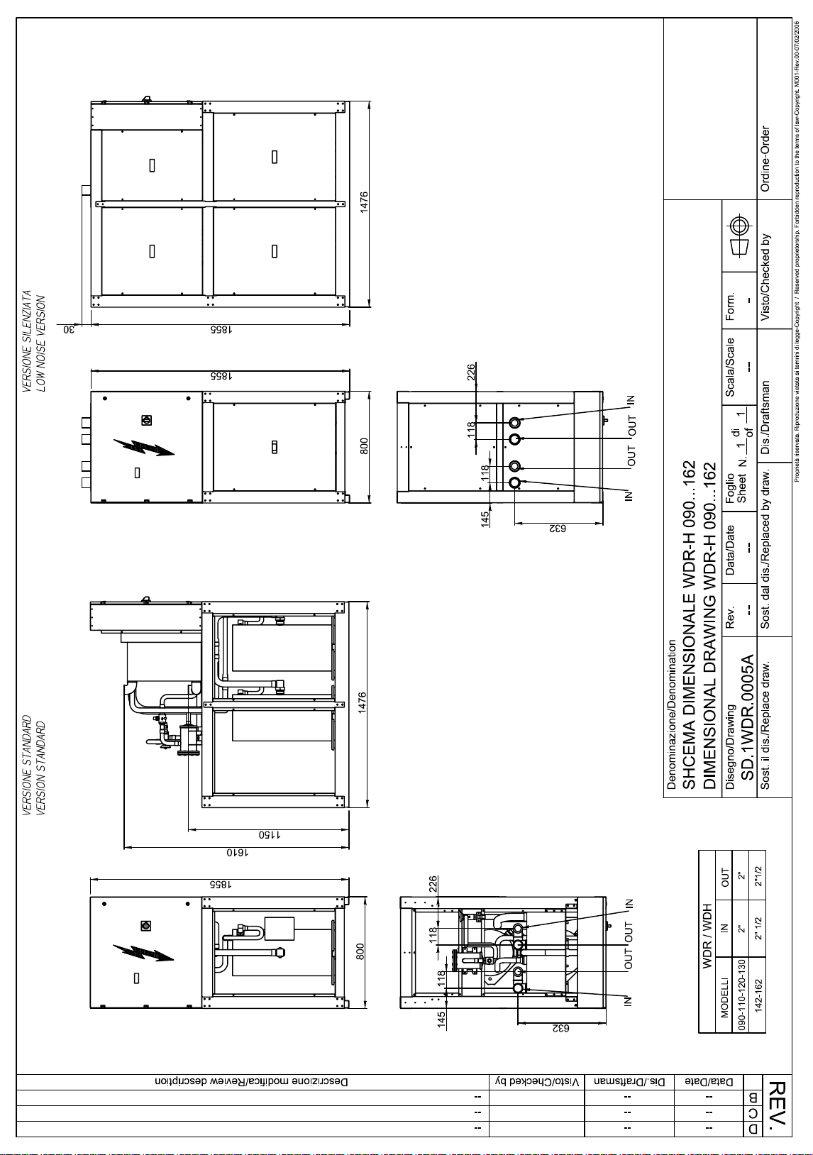
Page 41
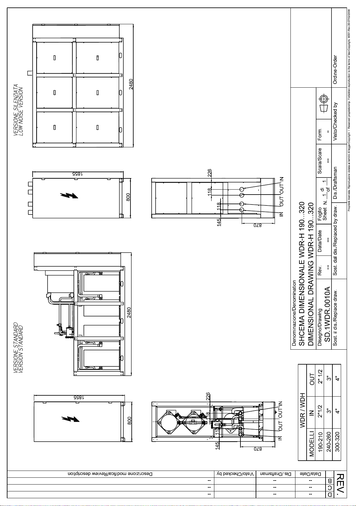
Page 42

WDH Ground source heat pumps
MTWDHGB REV.072008
39
Page 43

Page 44

HIDROS srl
Via dell’Industria 5
35020 Brugine (Pd)
Tel.+390-49-9731022
Fax.+390-49-5806928
t
IInnffoo@@hhiiddrrooss..iit
www.hidros.it
Technical data shown in this booklet are not binding.
HIDROS SRL shall have the right to introduce at any time whatever modifications necessary to the improvement of the product.
MTWDHGB REV.072008
 Loading...