

Page 1
15370 Barranca Parkway
Irvine, CA 92618
iCLASS SE Reader Module
HARDWARE DEVELOPER GUIDE
SE3200-902, Rev B.0
October 2012
© 2012 HID Global Corporation. All rights reserved.
HID GLOBAL CONFIDENTIAL AND PROPRIETARY INFORMATION. Use and disclosure of this information is strictly restricted
by the terms of the end user license agreement with HID Global Corporation. If you have received this information and are not an
intended recipient or are not subject to or do not agree to be bound by the terms of the non-disclosure agreement, please
immediately return this document to HID Global Corporation, 15370 Barranca Pkwy, Irvine, CA 92618-3106.
Page 2

Contents
1 Introduction ..................................................................................................................................... 6
1.1 Product Description ............................................................................................................. 6
1.1.1 Key Features ....................................................................................................................... 6
1.1.2 iCLASS SE Reader Module Products ................................................................................. 7
1.1.3 Product Guide ..................................................................................................................... 8
1.2 Scope/Purpose .................................................................................................................... 8
1.3 Terms and Abbreviations ..................................................................................................... 8
2 Overview ........................................................................................................................................ 10
2.1 Features............................................................................................................................. 10
2.2 Block Diagram ................................................................................................................... 11
2.3 Theory of Operation ........................................................................................................... 12
2.3.1 Power Modes .................................................................................................................... 12
2.3.2 Module – Transponder Interaction .................................................................................... 12
2.4 Peripheral Circuits ............................................................................................................. 13
2.4.1 External Pull-up Resistors ................................................................................................. 13
2.4.2 External Noise Filter .......................................................................................................... 13
2.4.3 Adding External LEDs and Beeper .................................................................................... 13
2.5 Transitioning from the OEM50, OEM75 and eProxL Modules .......................................... 13
2.5.1 OEM50 .............................................................................................................................. 13
2.5.2 OEM75 .............................................................................................................................. 14
2.5.3 eProx Lock Module ........................................................................................................... 14
3 Connector Configuration ............................................................................................................. 15
3.1 SE3200Axx Connectors .................................................................................................... 15
3.2 SE3210Axx Connectors .................................................................................................... 15
3.3 Pin Configuration ............................................................................................................... 16
3.3.1 P301 Host Interface Connector ......................................................................................... 16
3.3.2 P701 Power and I/O Connector ........................................................................................ 16
3.3.3 P702 Board to Board Connector ....................................................................................... 17
3.3.4 P401 HF Antenna Connector ............................................................................................ 17
3.3.5 E501/E502 Prox Antenna Connector ................................................................................ 18
4 Mechanical Specifications ........................................................................................................... 19
4.1 SE3200Axx ........................................................................................................................ 19
4.2 SE3210Axx ........................................................................................................................ 20
4.3 Connector Types ............................................................................................................... 21
4.3.1 SE3210Axx Connector Types ........................................................................................... 21
4.3.2 SE3200Axx Interconnect ................................................................................................... 21
5 Electrical Specifications .............................................................................................................. 22
5.1 Maximum Ratings .............................................................................................................. 22
5.2 Current Draw ..................................................................................................................... 22
5.3 Power Supply .................................................................................................................... 23
5.4 Host Interfaces .................................................................................................................. 23
Page 3

October 2012 Page 3 of 42
agreement, please immediately return this document to HID Global Corporation, 15370 Barranca Pkwy, Irvine, CA 92618-3106.
iCLASS SE Reader Module Hardware Developer Guide, SE3200-902, Rev B.0
5.5 Wiegand............................................................................................................................. 23
5.6 I/O ...................................................................................................................................... 24
5.7 Regulated Voltage Outputs ............................................................................................... 24
5.8 RF Interface (13.56 MHz) .................................................................................................. 24
5.9 RF Interface (125 kHz/Prox) .............................................................................................. 24
6 RF Interfaces ................................................................................................................................. 25
6.1 HF Interface (13.56 MHz) .................................................................................................. 25
6.1.1 Ultra Low Power Mode ...................................................................................................... 27
6.2 Prox Interface (125 kHz; SE32x0APx only) ....................................................................... 28
7 Antennas ....................................................................................................................................... 29
7.1 Basic Antenna Operation................................................................................................... 29
7.1.1 Inductive Coupling ............................................................................................................. 30
7.1.2 Load Modulation................................................................................................................ 31
7.2 Antenna Integration ........................................................................................................... 31
7.2.1 Steps to Integration ........................................................................................................... 31
7.2.2 Antenna Interconnect Cable .............................................................................................. 31
7.2.3 Training and Assistance .................................................................................................... 31
7.3 4090A10 HF Antenna ........................................................................................................ 32
7.3.1 Mechanical Data ............................................................................................................... 32
7.3.2 Typical Read Ranges with Standard Transponders .......................................................... 33
7.3.3 Typical Read Ranges with HID Multi Technology Cards ................................................... 34
7.3.4 ULPM Card Detection Range ............................................................................................ 34
7.3.5 RF Properties .................................................................................................................... 35
7.3.6 Power Considerations ....................................................................................................... 37
7.4 6500-101-03 Prox Antenna ............................................................................................... 38
7.4.1 Mechanical Data ............................................................................................................... 38
7.4.2 Electrical Characteristics ................................................................................................... 38
7.4.3 Typical Read Ranges ........................................................................................................ 39
8 Regulatory ..................................................................................................................................... 40
8.1 RoHS ................................................................................................................................. 40
8.2 REACH .............................................................................................................................. 40
8.3 Safety ................................................................................................................................. 40
8.4 Product Radio Certifications .............................................................................................. 40
8.5 FCC ................................................................................................................................... 41
8.6 Canada Radio Certification ..................................................................................... 41
8.7 CE Marking .................................................................................................................... 41
HID GLOBAL CONFIDENTIAL AND PROPRIETARY INFORMATION. Use and disclosure of this information is strictly
restricted by the terms of the end user license agreement with HID Global Corporation. If you have received this information
and are not an intended recipient or are not subject to or do not agree to be bound by the terms of the non-disclosure
Page 4

List of Figures
Figure 1: iCLASS SE Reader Module Block Diagram ................................................................................. 11
Figure 2: SE3200Axx Connector Configuration .......................................................................................... 15
Figure 3: SE3210Axx Connector Configuration .......................................................................................... 15
Figure 4: SE3200 Mechanical Drawing ....................................................................................................... 19
Figure 5: SE3210Axx Mechanical Drawing ................................................................................................. 20
Figure 6: Output Circuit Wiegand Interface ................................................................................................. 23
Figure 7: HF Interface .................................................................................................................................. 25
Figure 8: HF Interface with Coax Cable ...................................................................................................... 25
Figure 9: Basic Antenna Tuning Network .................................................................................................... 26
Figure 10: Tuning Network with ULPM Support .......................................................................................... 27
Figure 11: iCLASS SE Reader Module Prox Interface with Antenna .......................................................... 28
Figure 12: Inductive Coupling Principle ....................................................................................................... 30
Figure 13: Mutual Inductance between Reader and Transponder Antenna ............................................... 30
Figure 14: Load Modulation Principle .......................................................................................................... 31
Figure 15: 4090A10 HF Antenna ................................................................................................................. 32
Figure 16: 6500-101-03 Prox Antenna ........................................................................................................ 38
Figure 17: 6500-101-03 Mechanical Drawing ............................................................................................. 38
List of Tables
Table 1: Feature Overview .......................................................................................................................... 10
Table 2: P301 Pin Configuration.................................................................................................................. 16
Table 3: P701 Pin Configuration.................................................................................................................. 16
Table 4: P702 Pin Configuration.................................................................................................................. 17
Table 5: P401 Pin Configuration.................................................................................................................. 18
Table 6: E501/E502 Pin Configuration ........................................................................................................ 18
Table 7: SE3210 Connector Types ............................................................................................................. 21
Table 8: Maximum Ratings .......................................................................................................................... 22
Table 9: Power Considerations ................................................................................................................... 22
Table 10: Power Supply Electrical Characteristics ...................................................................................... 23
Table 11: Host Interface Electrical Characteristics ...................................................................................... 23
Table 12: Wiegand Electrical Characteristics – Host Interface ................................................................... 24
Table 13: I/O Electrical Characteristics – Host Interface ............................................................................. 24
Table 14: Regulated Voltage Output Electrical Characteristics .................................................................. 24
Table 15: 13.56 MHz RF Interface - Electrical Characteristics Power Supply ............................................ 24
Table 16: 125 kHz RF Interface - Electrical Characteristics Power Supply ................................................ 24
Table 17: 4090A10 HF Antenna with Standard ID1 Transponders Read Ranges ...................................... 33
Table 18: Typical Read Ranges 4090A10 HF Antenna - HID Multi Technology Cards .............................. 34
Table 19: ULPM Card Detection Ranges 4090A10 HF Antenna ................................................................ 35
Table 20: ISO/IEC14443 Type A Modulation Waveforms ........................................................................... 35
Table 21: ISO/IEC14443 Type B Modulation Waveforms ........................................................................... 36
Table 22: FeliCa Waveforms ....................................................................................................................... 36
Table 23: Power Considerations ................................................................................................................. 37
Table 24: Electrical Characteristics 6500-101-03 ........................................................................................ 39
Table 25: Typical Read Ranges 6500-101-03 Prox Antenna ...................................................................... 39
Page 5
October 2012 Page 5 of 42
agreement, please immediately return this document to HID Global Corporation, 15370 Barranca Pkwy, Irvine, CA 92618-3106.
July 2012
H. Pirch
Initial Version for internal Beta
A
North America
Europe, Middle East and Africa
Phoenix Road
Haverhill, Suffolk CB9 7AE
England
Connect_Europe@HIDGlobal.com
Asia Pacific
Copyright
© 2012 HID Global Corporation. All rights reserved.
Trademarks
HID GLOBAL, HID, the HID logo, iCLASS, iCLASS SE and SIO are the trademarks or
registered trademarks of HID Global Corporation, or its licensors, in the U.S. and other
countries.
Revision History
Date Author Description Document
Oct 2012 HP & IRC Changed contacts for HID Connect
iCLASS SE Reader Module Hardware Developer Guide, SE3200-902, Rev B.0
Version
B.0
1.3 Product guide removed table & inserted ref
to micro-site
1.1.3 Remove product guide table
Contacts
15370 Barranca Parkway
Irvine, CA 92618
USA
Connect_Americas@HIDGlobal.com
19/F 625 King’s Road
North Point, Island East
Hong Kong
Connect_APAC@HIDGlobal.com
HID GLOBAL CONFIDENTIAL AND PROPRIETARY INFORMATION. Use and disclosure of this information is strictly
restricted by the terms of the end user license agreement with HID Global Corporation. If you have received this information
and are not an intended recipient or are not subject to or do not agree to be bound by the terms of the non-disclosure
Page 6

1 Introduction
1.1 Product Description
The iCLASS SE® Reader is part of HID Global’s next generation platform. The iCLASS SE
Reader goes beyond the traditional smart card model offering secure and standards based
independent technology and flexible identity data structure based on Secure Identity Object™
®
). SIO is a portable and open credential methodology.
(SIO
Building on the success of the existing OEM modules (including the OEM50 and OEM75) the
iCLASS SE Reader enhances existing functionality with new SIO features. The new features
include supporting NFC smartphones and other devices for mobile access while also
providing increased levels of security.
The iCLASS SE Reader allows integrators to design third party solutions supporting a full
range of contactless card technologies, including iCLASS
provides PIV II compliance/ FIPS 201 certification and appears on the GSA Approved
Products List (APL) allowing straightforward integration into U.S. Government applications.
The iCLASS SE Reader’s dual frequency capability allows the use of both high and low
frequency credentials with the same reader, providing a solution for mixed credential and
credential migration applications.
Another key feature of the iCLASS SE Reader is the straightforward field upgrade support
that allows firmware changes and feature upgrades for installed readers to extend the
lifecycle of customer installations.
For quick and easy integration, HID Global also provides an iCLASS SE Reader Developer
Tool Kit (DTK). The DTK provides the necessary tools, documentation and developer
resources material to shorten integration cycles and speed time to market with finished
products.
1.1.1 Key Features
• Single platform supporting
o Secure Identity Object – Multi Layer security that extends beyond the card
technology, providing additional protection to identity data
o Dual Frequency and NFC Capability – Allows straightforward migration by
supporting low and high frequency credentials (including iCLASS
Indala Prox, FeliCa
enabled smartphones.
o Field upgradeability giving the installer the flexibility to implement new features
in the field and extending product lifecycle
• A complete flexible product line of reader boards, antennas and accessories.
• Developer tools and support. iCLASS SE Reader provides a fully featured
Development Tool Kit (DTK) providing web / desktop based tools and
documentation.
• Development support from HID Global Support Services
• Product pre-certification for industry standard bodies such as modular-FCC and CE
• FIPS 201 PIV II compliance with inclusion on the GSA APL
®
, MIFARE® and HID Prox. It also
™
MIFARE Classic and MIFARE DESFire EV1) and NFC
, HID Prox,
Page 7
October 2012 Page 7 of 42
agreement, please immediately return this document to HID Global Corporation, 15370 Barranca Pkwy, Irvine, CA 92618-3106.
iCLASS SE Reader Module Hardware Developer Guide, SE3200-902, Rev B.0
• Ultra low power mode for battery- operated devices
• EAL5+ certified secure element hardware for protection of keys and cryptographic
operations to guard against security threats
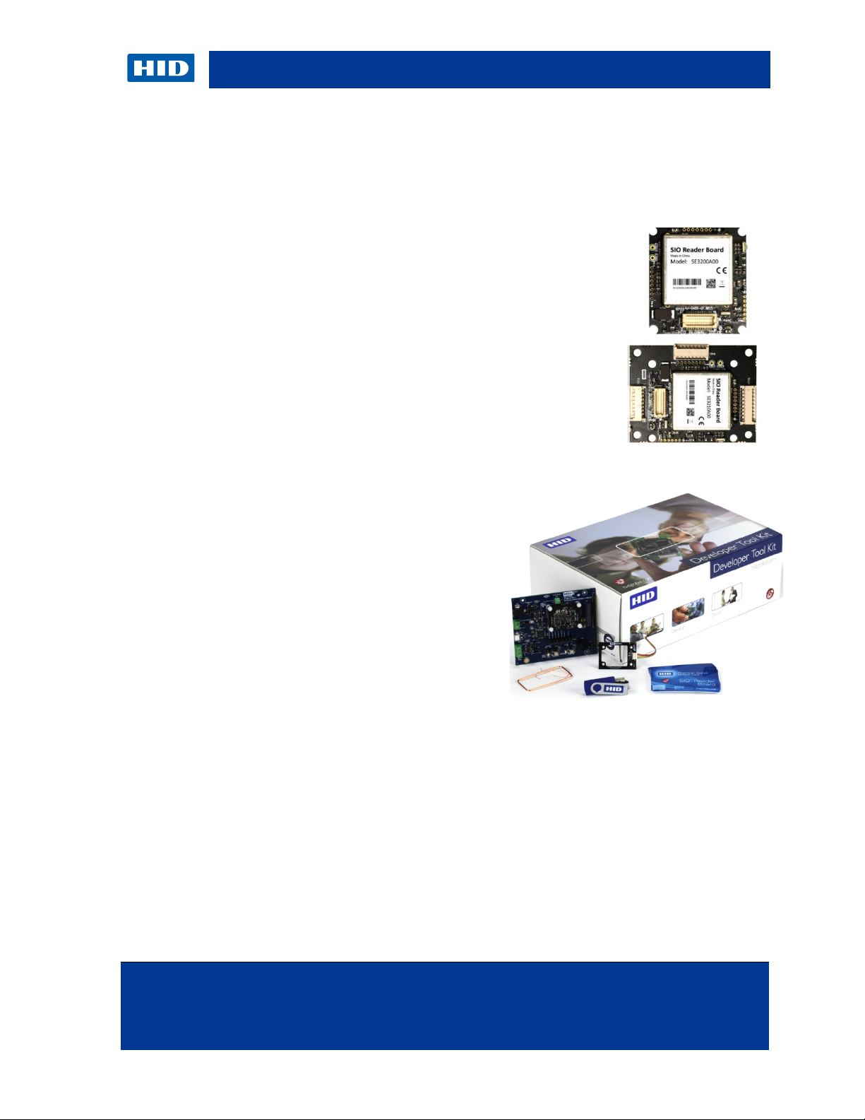
1.1.2 iCLASS SE Reader Module Products
The iCLASS SE Reader Module comes in two form factors.
• 3200 iCLASS SE Reader Module
Same form factor as OEM50
28mm x 30.5mm (1.10" x 1.20")
• 3210 iCLASS SE Reader Module
Same form factor as eProx-Lock module
33mm x 43mm (1.3" x 1.7")
Development Tool Kit
• Development Board
• 3200 and 3210 iCLASS SE Reader
Modules
• HF and LF Antennas and cables
• Sample Credentials
• Memory Stick containing development
tools and documentation
HID GLOBAL CONFIDENTIAL AND PROPRIETARY INFORMATION. Use and disclosure of this information is strictly
restricted by the terms of the end user license agreement with HID Global Corporation. If you have received this information
and are not an intended recipient or are not subject to or do not agree to be bound by the terms of the non-disclosure
Page 8
1.1.3 Product Guide
Abbreviation
Description
ANT
Antenna
ARM
Advanced RISK Machine
CSN
Card Serial Number
DNC
Do Not Connect
EMC
Electro Magnetic Compatibility
FSK
Frequency Shift Keying
FCC
Federal Communication Commission
HF
High Frequency (13.56 MHz)
LED
Light Emitting Diode
NPM
Normal Power Mode
PICC
Proximity IC Card
The iCLASS SE reader module comes in two form factors. It can also be configured for high
frequency card reading only or High & low frequency (prox).
In addition there are two different levels of security provided.
Key Security Notes:
Standard V1 Security: Standard Security (Version 1) Keyset – coupled with the Standard
13.56 MHz interpreter provides compatibility with iCLASS SE, iCLASS SR, standard iCLASS,
SE for MIFARE Classic and SE for MIFARE DESFire EV1 credentials.
Standard V2 Security: Standard Security (Version 2) Keyset – coupled with the SIO (Only)
13.56 MHz interpreter provides compatibility with iCLASS SE, MIFARE Classic SE and
MIFARE DESFire EV1 SE credentials
Elite Security: Elite reads only SE Elite™ credentials with unique matching keys. Works with
iCLASS SE, iCLASS SR, standard iCLASS, SE for MIFARE Classic and SE for MIFARE
DESFire EV1 with matching Elite keys. Requires ICE reference number.
Prox Reading Notes:
Standard Prox: HID Prox, AWID, EM4102 and Indala (10022 – 26-bit)
Custom Prox: HID Prox, AWID, EM4102 and Indala Custom format
For full ordering information including options, see the Embedded Technology Solutions How
to Order Guide:
http://www.hidglobal.com/documents/embedded_htog_en.pdf
1.2 Scope/Purpose
This document describes the hardware features of the iCLASS SE Reader Module. The
product is available in two form factors with various different configurations. Form factor and
host connectors are backward compatible to the OEM75 module.
1.3 Terms and Abbreviations
.
Page 9
October 2012 Page 9 of 42
agreement, please immediately return this document to HID Global Corporation, 15370 Barranca Pkwy, Irvine, CA 92618-3106.
FeliCa
Felicity Card
IC
Industry Canada (Industrie Canada)
I/O
Input / Output
LF
Low Frequency (125 kHz)
Optimized
Configured/Developed to operate at the best performance level
RF
Radio Frequency
RFID
Radio Frequency Identification
R&TTE
Radio and Telecommunications Terminal Equipment
SIO
Secure Identity Object
SPI
Serial Peripheral Interface
Ta
Ambient Temperature
TTL
Transistor – Transistor Logic
UART
Universal Asynchronous Receiver Transmitter
UID
Unique Identifier
UL
Underwriters Laboratories
USB
Universal Serial Bus
ULPM
Ultra Low Power Mode
iCLASS SE Reader Module Hardware Developer Guide, SE3200-902, Rev B.0
Abbreviation Description
HID GLOBAL CONFIDENTIAL AND PROPRIETARY INFORMATION. Use and disclosure of this information is strictly
restricted by the terms of the end user license agreement with HID Global Corporation. If you have received this information
and are not an intended recipient or are not subject to or do not agree to be bound by the terms of the non-disclosure
Page 10
2 Overview
Classic, MIFARE DESFire 0.6 & EV1
ISO/IEC15693
CSN only
Pico15693
ISO/IEC15693 with proprietary protocol
Pico14443B
ISO/IEC14443 Type B with proprietary protocol
HID iCLASS
ISO/IEC14443 and ISO/IEC15693 mode
FeliCa
CSN only
HID Prox
Indala Prox
SPI
UART
Suggested host interface
Wiegand
Output only binary interface
Operating Temperature
-25°C to 65°C
Storage Temperature
-45°C to 85°C
Humidity
0-90% non condensing
FCC & IC
FCC and Industry Canada Modular Approval
Immunity)
RoHS & REACH
Component
GSA
SE32x0Axx-G3.0 only (in process)
2.1 Features
Table 1: Feature Overview
Type Feature Comment
RF Interface
Host Interfaces
Environmental
Properties
ISO/IEC14443
ISO/IEC14443 Type A&B up to 848kbps, MIFARE
SE32x0APx only
CE Marking
Certifications
UL Recognized
R&TTE Directive (Emissions, Indirect ESD, RF
UL 294 (in process)
Page 11

October 2012 Page 11 of 42
agreement, please immediately return this document to HID Global Corporation, 15370 Barranca Pkwy, Irvine, CA 92618-3106.
2.2 Block Diagram
iCLASS SE Reader Module Hardware Developer Guide, SE3200-902, Rev B.0
Figure 1: iCLASS SE Reader Module Block Diagram
HID GLOBAL CONFIDENTIAL AND PROPRIETARY INFORMATION. Use and disclosure of this information is strictly
restricted by the terms of the end user license agreement with HID Global Corporation. If you have received this information
and are not an intended recipient or are not subject to or do not agree to be bound by the terms of the non-disclosure
Page 12

2.3 Theory of Operation
2.3.1 Power Modes
• Normal Power Mode (NPM) – The module is constantly powered on and polling for
cards. The module is never asleep in this mode. Use this mode with an external
power supply. The module is always ready to receive a command from the host.
• Ultra Low Power Mode (ULPM) – This power mode was designed for fixed
location battery powered applications (for example, door or cabinet lock). The
module is constantly monitoring the antenna for an impedance shift to detect a card
presented to the antenna. Once detecting an impedance shift on the HF antenna,
the module wakes up and polls for cards in the field. If a card is detected in the RF
field, the module reads the card data, pulses the Card Present line, outputs the card
data, and goes back to sleep within a configured period of time to conserve power.
Note: If developing a handheld unit, operate the iCLASS SE Reader Module in Normal
Power Mode and disable the power when not in use.
Power Autonomous
Mode
NPM
ULPM
2.3.2 Module – Transponder Interaction
• Autonomous Mode – The iCLASS SE Reader Module is intended to automatically
access and report the secure payload or the serial number (UID/CSN) of a
transponder. Thereby it acts on its protocols and applications configuration to
automatically report the payload on its Wiegand, UART and/or SPI ports.
Advanced Protocol Interface Mode (API) – The host communicates with the
transponder in the field through the iCLASS SE Reader Module’s serial protocol.
(UART or SPI is required)
Note: API calls are available in ULPM after the module outputs its autonomous data
(configuration dependant).
Autonomous & API Mode
after autonomous output
Page 13
October 2012 Page 13 of 42
agreement, please immediately return this document to HID Global Corporation, 15370 Barranca Pkwy, Irvine, CA 92618-3106.
Pin 1
Exc Supply
No signal on the SE32XX
Pin 2
Exc Return is not used
No signal on the SE32XX
Pin 3
Serial Transmit
Same as P301 pin 8 - UART Transmit
Pin 4
Serial Receive
Same as P301 pin 7 - UART Receive
Pin 5
Vdd Return
Same as P701 pin 2 - Battery Minus
and 5VDC is a good supply voltage
iCLASS SE Reader Module Hardware Developer Guide, SE3200-902, Rev B.0
2.4 Peripheral Circuits
The following section details recommended peripheral circuitry.
2.4.1 External Pull-up Resistors
External pull-up resistors may be required on the UART Tx and MOSI lines to prevent floating
I/O anomalies.
2.4.2 External Noise Filter
If false card detections occur in Ultra Low Power mode, or the host has spectral noise, a line
filter designed to block frequencies in the 10 KHz to 50 KHz range is beneficial when inline
with the power line.
2.4.3 Adding External LEDs and Beeper
The Cathodes are connected through an external resistor to the RED or GREEN LED
connector port signals. The OEM supplies current limiting resistors for modules.
The value of these resistors depends on how much current is provided for the LEDs.
Consider the combined voltage drop of the resistor and OEM75 output low voltage on these
signal lines when selecting the LED brightness.
2.5 Transitioning from the OEM50, OEM75 and eProxL Modules
Provided are suggestions for transitioning from the HID OEM50 and eProx Lock modules to
the OEM75.
2.5.1 OEM50
If you are transitioning from an OEM50 – here are the differences.
• The OEM50 connector is a 2 X 6 0.1" space pin header or PWB hole pattern.
• The OEM50 has a two-wire interface to the antenna and the iCLASS SE
Reader has a 2-wire interface for NPM and a 5-wire interface for ULPM
applications. Therefore, it is possible that the OEM50 antenna will work with
the SIO Processor Board in NPM.
• The harness and signal changes to adapt the signals from the OEM50 2 X 6
pattern to an OEM75 1 x 9 1.25mm pattern are the following.
Note: The additional P2 for HSI and SPI interfaces are 1 x 8 1.25mm pattern.
OEM50 SE32XX
P2 Connector
Pin 6 Vdd +5VDC
HID GLOBAL CONFIDENTIAL AND PROPRIETARY INFORMATION. Use and disclosure of this information is strictly
restricted by the terms of the end user license agreement with HID Global Corporation. If you have received this information
and are not an intended recipient or are not subject to or do not agree to be bound by the terms of the non-disclosure
Same as P701 pin 1 - Battery Positive
Page 14

OEM50
SE32XX
P1 Connector
Pin 1
Open Output
SE32XX does not have a similar signal
Pin 2
Ground
Same as P301 pin 2, signal Ground
OEM50 is inverted logic
Pin 5
Power On Reset
Same as P701 pin 3 /Reset function
Pin 6
Hold
Similar to P701 pin 4, however /Hold is low active
Pin 3 Wiegand Data1
Pin 4 Wiegand Data0
2.5.2 OEM75
The SE32XX module I/O is directly pin-for-pin compatible with the OEM75.
The OEM75 antennas are incompatible with the SE32XX module.
ULPM average current remains the same while peak current is higher for the SE32XX
module.
2.5.3 eProx Lock Module
The eProx
®
Lock connector is the same as the SE32XX connector P701.
Wiegand data output is per the SIA AC-01
(1996.10) specification, except Voh is 3.3VDC
max, and not 4.0 to 5.5 VDC
OEM50 is inverted logic
Wiegand data output is per the SIA AC-01
(1996.10) specification, except Voh is 3.3VDC
max, and not 4.0 to 5.5 VDC
CAUTION: The connections between the SE32XX and the eProx Lock modules are
reversed.
A straight-thru cable will not work. Twist the cable 180 degrees to ensure that Pin 1 on one
module correctly mates with Pin 1 on the other module.
The two-wire 125 kHz antenna for the eProx Lock may not be interchangeable with an
SE32XX Prox antenna.
Page 15

October 2012 Page 15 of 42
agreement, please immediately return this document to HID Global Corporation, 15370 Barranca Pkwy, Irvine, CA 92618-3106.
iCLASS SE Reader Module Hardware Developer Guide, SE3200-902, Rev B.0
3 Connector Configuration
3.1 SE3200Axx Connectors
Figure 2: SE3200Axx Connector Configuration
3.2 SE3210Axx Connectors
Figure 3: SE3210Axx Connector Configuration
HID GLOBAL CONFIDENTIAL AND PROPRIETARY INFORMATION. Use and disclosure of this information is strictly
restricted by the terms of the end user license agreement with HID Global Corporation. If you have received this information
and are not an intended recipient or are not subject to or do not agree to be bound by the terms of the non-disclosure
Page 16

3.3 Pin Configuration
+3.3 VDC
Output
0.1W maximum power sourced output
GND
Reference
Logic level reference
SPI_CLK
Input
SPI clock signal
SPI_nCS
Input
SPI chip select (active low)
SPI_MOSI
Input
SPI data in
SPI_MISO
Output
SPI data out
URX
Input
UART data in
UTX
Output
UART data out
1
VIN
Supply
Supply Voltage Positive
2
VRTN
Supply
Supply Voltage Negative
3
nReset
Input
Reset (active low)
released, as configured (active low)
output on the configured host interface.
6
WG_DATA0
Output
Wiegand Data 0
7
WG_DATA1
Output
Wiegand Data 1
Signal which enables off board signaling
board LED
3.3.1 P301 Host Interface Connector
This connector is compatible with P1 of the OEM75 module.
Table 2: P301 Pin Configuration
Pin Signal Name Type Function
1
2
3
4
5
6
7
8
3.3.2 P701 Power and I/O Connector
This connector is compatible with P2 of the OEM75 module.
Table 3: P701 Pin Configuration
Pin Signal Name Type Function
4 nHold Input
5 nGLED_CPRES Output
8 nBEEPER Output
9 nRLED Output
Signal that holds off the presentation of the
card data. When asserted, this line either
buffers a card or disables a card read until
The signal on this pin reflects the recognition
of a card near the antenna. The autonomous
read and buffered data from the credential is
Signal which can be used to enable an off
Page 17

October 2012 Page 17 of 42
agreement, please immediately return this document to HID Global Corporation, 15370 Barranca Pkwy, Irvine, CA 92618-3106.
released, as configured (active low)
2
VIN
Supply
Supply Voltage Positive
3
NC Not Connected
4
VIN
Supply
Supply Voltage Positive
5
NC
6
VRTN
Supply
Supply Voltage Negative
7
URX
Input
UART data in
8
SPI_MISO
Output
SPI data out
9
UTX
Output
UART data out
10
SPI_MOSI
Input
SPI data in
12
VRTN
Supply
Supply Voltage Negative
13
WG_DATA0
Output
Wiegand Data 0
14
DNC
Do Not Connect
15
DNC
Do Not Connect
16
DNC
Do Not Connect
17
DNC
Do Not Connect
18
nReset
Input
Reset (active low)
19
+3.3VDC
Output
0.1W maximum power sourced output
20
VRTN
Supply
Supply Voltage Negative
output on the configured host interface.
22
SPI_CLK
Input
SPI clock signal
23
nBeeper
Output
Signal which enables off board signaling
24
SPI_nCS
Input
SPI chip select (active low)
25
NC Not Connected
26
VRTN
Supply
Supply Voltage Negative
27
DNC
Do Not Connect
board LED
29
DNC
Do Not Connect
30
NC Not Connected
iCLASS SE Reader Module Hardware Developer Guide, SE3200-902, Rev B.0
3.3.3 P702 Board to Board Connector
This connector is an alternative interconnection method to P301 and P701.
Table 4: P702 Pin Configuration
Pin Signal Name Type Function
1 nHold Input
11 WG_DATA1 Output Wiegand Data 1
Signal that holds off the presentation of the
card data. When asserted, this line either
buffers a card or disables a card read until
The signal on this pin reflects the recognition
21 nGLED_CPRES Output
28 nRLED Output
of a card near the antenna. The autonomous
read and buffered data from the credential is
Signal which can be used to enable an off
3.3.4 P401 HF Antenna Connector
HID GLOBAL CONFIDENTIAL AND PROPRIETARY INFORMATION. Use and disclosure of this information is strictly
restricted by the terms of the end user license agreement with HID Global Corporation. If you have received this information
and are not an intended recipient or are not subject to or do not agree to be bound by the terms of the non-disclosure
Page 18

This antenna connection IS NOT compatible with an OEM75 antenna.
Pin
Signal Name
Type
Function
1
ATX
Output
13.56 MHz antenna driving signal
2
GND
Reference
Antenna ground reference
3
PING_LVL
Input
4
PING_SIG
Output
5
PING_EN
Output
E501
PROX_TX1
Output
E502
PROX_TX2
Output
Table 5: P401 Pin Configuration
3.3.5 E501/E502 Prox Antenna Connector
Table 6: E501/E502 Pin Configuration
Pin Signal Name Type Function
Signals for low power card detection in ULPM
125 kHz antenna driving signal
Page 19

October 2012 Page 19 of 42
agreement, please immediately return this document to HID Global Corporation, 15370 Barranca Pkwy, Irvine, CA 92618-3106.
iCLASS SE Reader Module Hardware Developer Guide, SE3200-902, Rev B.0
4 Mechanical Specifications
The following section details the mechanical specifications for the iCLASS SE Reader Module
and its connectors. Detailed drawings are also available at the iCLASS SE Reader Module
micro-site.
4.1 SE3200Axx
This form factor is compatible with OEM75 model 3141ADx.
Figure 4: SE3200 Mechanical Drawing
HID GLOBAL CONFIDENTIAL AND PROPRIETARY INFORMATION. Use and disclosure of this information is strictly
restricted by the terms of the end user license agreement with HID Global Corporation. If you have received this information
and are not an intended recipient or are not subject to or do not agree to be bound by the terms of the non-disclosure
Page 20

4.2 SE3210Axx
This form factor is compatible with OEM75 modules 3141AAx, 3141AEx and 3141ACx.
Figure 5: SE3210Axx Mechanical Drawing
Page 21

October 2012 Page 21 of 42
agreement, please immediately return this document to HID Global Corporation, 15370 Barranca Pkwy, Irvine, CA 92618-3106.
Mates with: Molex 05102 series
Mates with: Molex 05102 series
Mates with: DF12-DS series
Mates with: Molex 05102 series
module for non potted integrations)
iCLASS SE Reader Module Hardware Developer Guide, SE3200-902, Rev B.0
4.3 Connector Types
4.3.1 SE3210Axx Connector Types
The following connectors are used for interconnection with host and antenna.
Table 7: SE3210 Connector Types
Connector Function Type / Counterpart
P301
P701 Wiegand and I/Os
P702
Power supply and host
interfaces
Alternative connection to P301
and P702
Manufacturer: Molex
Type: PicoBlade
Part Number: 53048-0810
Manufacturer: Molex
Type: PicoBlade
Part Number: 53048-0910
Manufacturer: Hirose Electric
Type: Board to Board
Part Number: DF12D(5.0)-30DP-
0.5 VDC
P401 HF Antenna
E501 / E502 Prox Antenna
4.3.2 SE3200Axx Interconnect
The SE3200Axx is designed as the smallest form factor possible. This module offering was
designed to be header mounted on a host board utilizing the P301 and P701 through-hole
connections. Use P702 as an alternative board-to-board connection if preferred.
Some header sources are:
• Cherng Weei
• HLCO
Each company’s part drawings are located on the DTK micro-site.
Manufacturer: Molex
Type: PicoBlade
Part Number: 53048-0510
Direct connect solder to module - no
connector (It is recommended that the Prox
antenna also be strain relieved by applying
epoxy to adhere the antenna leads to the
HID GLOBAL CONFIDENTIAL AND PROPRIETARY INFORMATION. Use and disclosure of this information is strictly
restricted by the terms of the end user license agreement with HID Global Corporation. If you have received this information
and are not an intended recipient or are not subject to or do not agree to be bound by the terms of the non-disclosure
Page 22

5 Electrical Specifications
Operating Temperature
-25°C to 65°C
Storage Temperature
-45°C to 85°C
Maximum Operating Voltage
10 VDC
No Prox
(HF deactivated)
Average DC current at 20°C
50 mA
5.1 Maximum Ratings
Stresses beyond those listed may cause permanent damage to the device. This is a stress
rating and functional operation of the device at these or other conditions (beyond those
indicated in the operational sections) is not implied. Exposure to absolute maximum rating
conditions for extended periods may affect device reliability.
Table 8: Maximum Ratings
5.2 Current Draw
The following measurements were performed with a 50 Ohm load connected to the HF
interface. In the case a real antenna is connected to the iCLASS SE Reader Module’s power,
consumption changes depending on the presence of a transponder and its relative position to
the antenna. For that reason, find guidance for changing power consumption for particular
antennas in section 6 RF Interfaces.
The power consumption is independent of the supply voltage, as the iCLASS SE Reader
Module uses a linear regulation system.
Table 9: Power Considerations
Mode Parameter Min Typ Max Unit
Normal Power Mode
Polling for HF transponders
in autonomous mode
Normal Power Mode
Polling for Prox Credentials
1
Average DC current at 20°C 40 mA
Peak Current 2 at 20°C 81 mA
Peak Current 2 at 20°C 80 mA
1
vary the power consumption.
2
field. The peak currents are also considered in the average current measurement.
Average DC current at 20°C 8.5 µA
Ultra Low Power Mode
Peak Current 2 at 20°C 24 µA
Polling cycle includes ISO/IEC14443 Type A and Pico15693. Adding additional protocols to the polling cycle may
When the carrier is turned on, the current consumption of the module may build to create the required magnetic
Page 23

October 2012 Page 23 of 42
agreement, please immediately return this document to HID Global Corporation, 15370 Barranca Pkwy, Irvine, CA 92618-3106.
Signal
Parameter
Min
Typ
Max
Unit
Input Voltage SE32x0A0x
3.60
4.00
10.00
VDC
Input Voltage SE32x0APx
4.95
5.25
10.00
VDC
Current Consumption Normal Operation
mA
Mode
Signal
Parameter
Min
Typ
Max
Unit
Input Voltage
-0.5 7
VDC
High-level Input Voltage
2.31
VDC
Low-level Input Voltage
0.99
VDC
Input Leakage Current
±0.1 µA
High-level Output Voltage
2.9 VDC
Low-level Output Voltage
0.4
VDC
Output Current
2
mA
UART
Baudrate
576k
Baud
SPI
Baudrate
300k
Baud
5.3 Power Supply
Table 10: Power Supply Electrical Characteristics
VIN
Current Consumption Ultra Low Power
Note: The power consumption depends on the operation mode and the connected antenna /
tuning. See section 4 Mechanical Specifications.
5.4 Host Interfaces
The host interface signals are backward compatible with the OEM75 product.
Table 11: Host Interface Electrical Characteristics
SPI_nCS
SPI_CLK,
SPI_MOSI
URX
iCLASS SE Reader Module Hardware Developer Guide, SE3200-902, Rev B.0
µA
SPI_MISO
UTX
5.5 Wiegand
The Wiegand interface signals are backward compatible with the OEM75 product.
Figure 6: Output Circuit Wiegand Interface
HID GLOBAL CONFIDENTIAL AND PROPRIETARY INFORMATION. Use and disclosure of this information is strictly
restricted by the terms of the end user license agreement with HID Global Corporation. If you have received this information
and are not an intended recipient or are not subject to or do not agree to be bound by the terms of the non-disclosure
Page 24

Table 12: Wiegand Electrical Characteristics – Host Interface
Signal
Parameter
Min
Typ
Max
Unit
WG_DATA0
WG_DATA1
Current Draw (into 1K +
10ohms)
WG_DATA0
WG_DATA1
Signal
Parameter
Min
Typ
Max
Unit
nRLED
Low-level Input Voltage
0.2
VDC
High-level Input Voltage
1.6
5.5
VDC
Low-level Input Voltage
0.2
VDC
High-level Input Voltage
1.6
5.5
VDC
Signal
Parameter
Min
Typ
Max
Unit
Output Voltage
3.168
3.3
3.432
VDC
Output Current
30
mA
ATX
Output Power
750
1000
mW
PING_EN
PROX_TX2
2.6(*) mA
High Level Output Voltage
5.6 I/O
The I/O signals are backward compatible to the OEM75 product.
Table 13: I/O Electrical Characteristics – Host Interface
nGLED_CPRES
nBEEPER
nReset
nHold
Current Draw
(Open Collector)
5.7 Regulated Voltage Outputs
Table 14: Regulated Voltage Output Electrical Characteristics
+3V3
Note: The regulated voltage output is deactivated if the module is in Ultra Low Power mode.
2.6
60 mA
VDC
5.8 RF Interface (13.56 MHz)
Table 15: 13.56 MHz RF Interface - Electrical Characteristics Power Supply
Signal Parameter Min Typ Max Unit
PING_LVL
PING_SIG
Connect according to 6.1.1 Ultra Low Power Mode.
Note: The output power depends on the connected antenna and its impedance. For optimum
performance, a 50Ω tuned antenna is recommended.
5.9 RF Interface (125 kHz/Prox)
Table 16: 125 kHz RF Interface - Electrical Characteristics Power Supply
Signal Parameter Min Typ Max Unit
PROX_TX1
Output Peak Current
200 mA
Page 25

October 2012 Page 25 of 42
agreement, please immediately return this document to HID Global Corporation, 15370 Barranca Pkwy, Irvine, CA 92618-3106.
SIO Reader Board
P401
Tuning
Network
Antenna
Pin1-ATX
Pin2-GND
50 Ohm
Coax Cable
iCLASS SE Reader Module Hardware Developer Guide, SE3200-902, Rev B.0
6 RF Interfaces
Depending on the configuration, the iCLASS SE Reader Module offers up to two different RF
interfaces.
• HF interface for 13.56 MHz transponders
• Prox interface for 125 kHz transponders (SE32x0APx only)
6.1 HF Interface (13.56 MHz)
The HF interface is optimized for operation with 50Ω tuned antennas.
Figure 7: HF Interface
The impedance of 50Ω allows for integrated antennas, as well as remote antennas
connected through a coax cable. Use a coaxial connection whenever operating the module in
Normal Power Mode, if possible.
Figure 8: HF Interface with Coax Cable
HID GLOBAL CONFIDENTIAL AND PROPRIETARY INFORMATION. Use and disclosure of this information is strictly
restricted by the terms of the end user license agreement with HID Global Corporation. If you have received this information
and are not an intended recipient or are not subject to or do not agree to be bound by the terms of the non-disclosure
Page 26

Realize a simple tuning network by using two capacitors, one serial and one parallel.
Figure 9: Basic Antenna Tuning Network
Za Antenna impedance
Cs Serial Capacitor
Cp Parallel Capacitor
Rp Parallel damping resistor for Q-factor control
Ra Serial antenna resistance
La Antenna inductance
For the capacitors C0G or NP0, dielectrics with a voltage rating larger than 50 VDC are
recommended.
In practice, Cs and Cp may consist of several parallel capacitors to get better granularity.
Be aware that HID is offering further documents, support and services in terms of antenna
design and support. These might require special or service level agreements. Contact your
sales manager for details about this offering.
Page 27

October 2012 Page 27 of 42
agreement, please immediately return this document to HID Global Corporation, 15370 Barranca Pkwy, Irvine, CA 92618-3106.
iCLASS SE Reader Module Hardware Developer Guide, SE3200-902, Rev B.0
6.1.1 Ultra Low Power Mode
To allow for the ULPM, take additional measures at the antenna circuit. A transistor, as well
as two additional measurement lines, is introduced to enable the low power card detection
circuit on the iCLASS SE Reader Module.
Figure 10: Tuning Network with ULPM Support
For Transistor Q1, a ZXM61N02F type or similar is recommended.
Note: Only the HF interface is capable of detecting transponders in ULPM. However, Prox
transponders may be recognized by the HF interface. If supporting Prox credentials in the
ULPM, concentrically rearrange the Prox and HF antenna.
HID GLOBAL CONFIDENTIAL AND PROPRIETARY INFORMATION. Use and disclosure of this information is strictly
restricted by the terms of the end user license agreement with HID Global Corporation. If you have received this information
and are not an intended recipient or are not subject to or do not agree to be bound by the terms of the non-disclosure
Page 28

6.2 Prox Interface (125 kHz; SE32x0APx only)
The Prox interface is optimized for connection to the HID Prox antenna 6500-101-03. If this
antenna or one with equal electrical characteristics is used, no additional components are
required.
Figure 11: iCLASS SE Reader Module Prox Interface with Antenna
The onboard capacitor of 2nF and the external antenna coil build a serial resonator. Choose
approximately 125 kHz for the resonance frequency. An additional 33Ω resistor is used to
control the quality factor of the antenna.
If the used antenna has a different electrical characteristic than the HID 6500-101-03 Prox
antenna, external components may be necessary to adjust resonance frequency and quality
factor to the desired value.
The desired quality factor of the system is between 5 and 15 depending on antenna size.
HID provides additional documents, support and services for antenna design and support.
These documents may require service level agreements. Contact your sales manager for
more details.
Page 29

October 2012 Page 29 of 42
agreement, please immediately return this document to HID Global Corporation, 15370 Barranca Pkwy, Irvine, CA 92618-3106.
iCLASS SE Reader Module Hardware Developer Guide, SE3200-902, Rev B.0
7 Antennas
All antennas offered for the iCLASS SE Reader Module are optimized for a free air
environment. A free air environment is one in which there are no external effects on the field
produced by the antenna and which might degrade its performance (for example, metal or
stray capacitance).
When an air-tuned antenna is placed near metal, its tuning is affected causing a degradation
of read performance.
All air-tuned antennas are optimized for a 50mm interconnect cable length. Different cable
lengths may also lead to performance degradation and optimization may be required.
Environment deviations (from free air, as well as antenna interconnect cable length and
routing the HF antenna interconnect cable along metal) require performing antenna
optimization to ensure that the RF interface operates optimally within the integrated
environment. It is suggested that the antenna and antenna interconnect cable be integrated
into the end product to mirror a free air environment.
7.1 Basic Antenna Operation
Credentials obtain their power from the magnetic field generated by the antenna of the
reader. At the operating frequency of the reader, this interaction is similar to the operation of
an air core transformer. When an antenna is energized by an alternating current, the induced
magnetic field is directly proportional to the area enclosed by the antenna loop. The larger
the loop, the more excitation current is required to produce the same level of magnetic flux.
That flux covers a larger area and so the read range is extended. Other external factors
affect the magnitude of this induced magnetic field. Magnetic lines of flux when generated by
a loop antenna are oriented perpendicular to the plane of the loop. This is known as the
right-hand rule, the magnetic field wraps around the wire in the direction of current flow.
HID GLOBAL CONFIDENTIAL AND PROPRIETARY INFORMATION. Use and disclosure of this information is strictly
restricted by the terms of the end user license agreement with HID Global Corporation. If you have received this information
and are not an intended recipient or are not subject to or do not agree to be bound by the terms of the non-disclosure
Page 30

7.1.1 Inductive Coupling
An inductively coupled transponder usually consists of a single chip and an attached coil,
which is used as an antenna.
Most inductively coupled transponders are passive, meaning that power is supplied by the
reader. To this end, the reader produces a magnetic field that the transponder uses for
power.
Figure 12: Inductive Coupling Principle
Mathematically, treat the coupling as a simple alternating magnetic field. The wavelength at
the frequencies of interest is much higher than the distance between the tag and reader (22.1
m at 13.56 MHz). Both antenna coils (transponder and reader) have a parallel capacitor,
creating a parallel resonant circuit. The capacitor is chosen to achieve a resonance frequency
near the working / carrier frequency of 13.56 MHz.
Interpret the arrangement of the two coils as a loosely coupled transformer, with a coupling
factor that varies with position and geometry.
Figure 13: Mutual Inductance between Reader and Transponder Antenna
Page 31

October 2012 Page 31 of 42
agreement, please immediately return this document to HID Global Corporation, 15370 Barranca Pkwy, Irvine, CA 92618-3106.
7.1.2 Load Modulation
As previously mentioned, interpret the inductively coupled system as a transformer. Putting a
transponder (with a SRF around 13.56 MHz) into the magnetic field of a reader absorbs
energy from the field. This loading of the reader’s antenna, caused by the transponder, is
represented as transformed impedance at the antenna.
To communicate with the reader, the transponder switches an additional load resistor across
its own antenna. This results in a further impedance / voltage change at the reader’s antenna.
Therefore, the credential does not actually transmit.
iCLASS SE Reader Module Hardware Developer Guide, SE3200-902, Rev B.0
Figure 14: Load Modulation Principle
7.2 Antenna Integration
Magnetic field antennas operate optimally within a free-air environment because the magnetic
field propagates perpendicularly with equal magnitude to the back and front of the antenna.
Antenna performance degradation due to Eddy Current loss begins at the point where a
metallic plate begins to enter the periphery of the magnetic flux lines of the magnetic field.
Note: Magnetic field losses due to Eddy Currents are not recoverable.
Magnetic field loss is extremely important. As loss increases, the available magnetic field to
power a credential and for the credential to load modulate is reduced, thus, affecting RF
performance of the system.
7.2.1 Steps to Integration
Due to antenna parasitic shift and eddy current losses, RF implementation should be fully
planned out prior to an industrial/mechanical design. This requires experimentation to be
completed including the proximity of metal obstructions in the proximity of the antenna
(including the LF antenna for HF+LF applications).
7.2.2 Antenna Interconnect Cable
The antenna interconnect cable is also designed to be routed in a free air environment.
Routing the antenna interconnect cable across metal structures shifts the antenna
characteristics and requires optimization.
7.2.3 Training and Assistance
HID GLOBAL CONFIDENTIAL AND PROPRIETARY INFORMATION. Use and disclosure of this information is strictly
restricted by the terms of the end user license agreement with HID Global Corporation. If you have received this information
and are not an intended recipient or are not subject to or do not agree to be bound by the terms of the non-disclosure
Page 32

HID Connect Applications Engineering staff will provide RF integration review and conceptual
training for integrators. In addition, HID provides antenna optimization and design services
through a Customer Product Opportunity Program.
7.3 4090A10 HF Antenna
Figure 15: 4090A10 HF Antenna
The 4090A10 HF antenna has an impedance of 50Ω and is optimized for operation with a
50mm ribbon cable. The antenna is tuned for a free air environment.
7.3.1 Mechanical Data
Detailed drawings are available at the iCLASS SE Reader micro-site.
Page 33

October 2012 Page 33 of 42
agreement, please immediately return this document to HID Global Corporation, 15370 Barranca Pkwy, Irvine, CA 92618-3106.
14.64
50
15.17
50
(MF0ICU2)
Semiconductors
14.04
55
14.81
50
15.83
40
(MF1S70)
Semiconductors
15.28
50
15.34
40
(MF1PLUSx0)
Semiconductors
14.94
40
15.37
45
15.50
40
15.00
45
15.73
40
15.05
40
15.68
35
16.07
40
16.34
35
(P5CD081)
15.21
20
15.34
20
13.63
100
13.86
80 14.14
70
iCLASS 16k
HID Global
ID1 Card
ISO/IEC15693
13.67
95
iCLASS SE Reader Module Hardware Developer Guide, SE3200-902, Rev B.0
7.3.2 Typical Read Ranges with Standard Transponders
The following read ranges are for indication only. The read range of a transponder may vary
significantly depending on antenna size and quality factor. Table 17: 4090A10 HF Antenna
with Standard ID1 Transponders shows tested card self-resonance frequency to provide an
indication for the antenna design difference.
For these read range tests, the transponder serial number was read. No cryptographic
operations were performed.
Table 17: 4090A10 HF Antenna with Standard ID1 Transponders Read Ranges
Transponder /
IC T ype
MIFARE Ultralight
(MF0ICU1)
Manufacturer Form Factor
ID1 Card
NXP
Semiconductors
Standard /
Modulation Scheme
ISO/IEC14443 (Type A)
SRF
[MHz]
14.51 55
Typical
Read
Range
[mm]
MIFARE Ultralight C
MIFARE Classic
(MF1S50)
MIFARE Classic
MIFARE Classic
(SLE66CL160S)
MIFARE Plus X
MIFARE DESFire
(MF3ICD40)
MIFARE DESFire
EV1 (MF3ICD21)
SLE55R16
SmartMX
(P5CD072)
SmartMX
CD21 ITSO
iCLASS 32k HID Global
NXP
NXP
Semiconductors
NXP
Infineon
Technologies
NXP
NXP
Semiconductors
NXP
Semiconductors
Infineon
Technologies
NXP
Semiconductors
NXP
Semiconductors
Oberthur Card
Systems
ID1 Card
ID1 Card
ID1 Card
ID1 Card
ID1 Card
ID1 Card
ID1 Card
ID1 Card
ID1 Card
ID1 Card
ID1 Card
ID1 Card
ISO/IEC14443 (Type A) 14.12 40
ISO/IEC14443 (Type A)
ISO/IEC14443 (Type A) 15.22 45
ISO/IEC14443 (Type A)
ISO/IEC14443 (Type A) 15.58 45
ISO/IEC14443 (Type A)
ISO/IEC14443 (Type A)
ISO/IEC14443 (Type A)
ISO/IEC14443 (Type A)
ISO/IEC14443 (Type A) 16.85 20
ISO/IEC14443 (Type B)
ISO/IEC15693
HID GLOBAL CONFIDENTIAL AND PROPRIETARY INFORMATION. Use and disclosure of this information is strictly
restricted by the terms of the end user license agreement with HID Global Corporation. If you have received this information
and are not an intended recipient or are not subject to or do not agree to be bound by the terms of the non-disclosure
Page 34

Transponder /
iCLASS 2k
HID Global
ID1 Card
ISO/IEC15693
13.48
95
(SRF55V02P)
(SRF55V10S)
(SL2ICS20)
(SL2ICS53)
13.68
110
13.89
90
13.52
65
14.15
50
13.57
35
13.58
35
Card Type
Manufacturer
Standard /
Modulation Scheme
Chip
Typical Read
Range[mm]
MIFARE / Prox
HID Global
ISO/IEC14443 (Type A)
MIFARE
40
DESFire / Prox
HID Global
ISO/IEC14443 (Type A)
DESFire
35
ISO/IEC14443 (Type A)
MIFARE
45
ISO/IEC15693
iCLASS
60
DESFire / Prox
ISO/IEC14443 (Type A)
DESFire
40
ISO/IEC15693
iCLASS
50
IC T ype
Manufacturer Form Factor
Standard /
Modulation Scheme
SRF
[MHz]
Typical
Read
Range
[mm]
My-d vicinity plain
My-d vicinity secure
Tag-it HF-I Plus
ICODE SLI
ICODE SLI-S
LRi2K
FeliCa RC-S962 Sony Corporation
FeliCa RC-S915 Sony Corporation
Infineon
Technologies
Infineon
Technologies
Texas
Instruments
NXP
Semiconductors
NXP
Semiconductors
ST
Microelectronics
ID1 Card
ID1 Card
ID1 Card
ID1 Card
ID1 Card
ID1 Card
ID1 Card
ID1 Card
ISO/IEC15693 13.93 90
ISO/IEC15693 14.44 75
ISO/IEC15693 13.74 70
ISO/IEC15693 13.38 80
ISO/IEC15693 13.68 120
ISO/IEC15693
FeliCa
FeliCa
7.3.3 Typical Read Ranges with HID Multi Technology Cards
For this read range tests the serial number of each individual HF chip inside the multi
technology card was read. For Prox read ranges, see Section 7.4 6500-101-03 Prox
Antenna.
Note: Read range varies depending on the transponders antenna size, design, SRF and
Quality.
Table 18: Typical Read Ranges 4090A10 HF Antenna - HID Multi Technology Cards
iCLASS /
MIFARE / Prox
iCLASS /
HID Global
HID Global
7.3.4 ULPM Card Detection Range
The card detection range in Ultra Low Power Mode depends on the loading effect the
transponder imposes on the iCLASS SE Reader Module’s antenna. That means that cards
with lower loading effect will generally have a shorter detection range.
Page 35

October 2012 Page 35 of 42
agreement, please immediately return this document to HID Global Corporation, 15370 Barranca Pkwy, Irvine, CA 92618-3106.
Transponder /
Manufacturer
SRF[MHz]
Typical Detection
MIFARE Ultralight (MF0ICU1)
NXP Semiconductors
14.51
55
MIFARE Classic (MF1S50)
NXP Semiconductors
14.04
55
MIFARE DESFire (MF3ICD40)
NXP Semiconductors
15.37
45
iCLASS 32k
HID Global
13.63
90
FeliCa RC-S962
Sony Corporation
13.52
85
H
iCLASS SE Reader Module Hardware Developer Guide, SE3200-902, Rev B.0
The following table provides an overview of typical detection ranges with some transponders.
Table 19: ULPM Card Detection Ranges 4090A10 HF Antenna
IC T ype
Note: If the card detection range exceeds the actual read range, the reader may wake up but
not read the transponder successfully at this distance.
7.3.5 RF Properties
Provided is an overview on the RF properties of the 4090A10 HF antenna in combination with
the iCLASS SE Reader Module. The modulation waveforms were measured at a distance of
10mm. Parameters may vary per unit due to component tolerances. The compliance of the
modulation waveforms is essential to ensure the interoperability with various transponders in
the field.
All measurements were performed in accordance to the ISO/IEC10373-6 standard.
Note: The following graph shows that at distances smaller than 12mm, the detuning of the
Reference PICC used for the measurement causes the field strength to decrease. Observe
similar behavior with transponders that introduce a loading effect of similar magnitude.
Range[mm]
4090A10 Magnetic Field Strength H
3.5
3
2.5
2
H[A/m]
1.5
1
0.5
0
2 4 6 8 10 12 14 16 18 20
d[mm]
Table 20: ISO/IEC14443 Type A Modulation Waveforms
T1
Pause Length
HID GLOBAL CONFIDENTIAL AND PROPRIETARY INFORMATION. Use and disclosure of this information is strictly
restricted by the terms of the end user license agreement with HID Global Corporation. If you have received this information
and are not an intended recipient or are not subject to or do not agree to be bound by the terms of the non-disclosure
2.52µs
Page 36

T2
Low Time
520ns
Table 21: ISO/IEC14443 Type B Modulation Waveforms
T3
Rise Time to 90%
T4
Rise Time to 60%
Overshoot 8.53%
Tr
Rise Time
Tf
Fall Time
Modulation Index 10.13%
325ns
98ns
720ns
510ns
Table 22: FeliCa Waveforms
Overshoot 1.2%
Undershoot 0.9%
Tr
Rise Time
730ns
Page 37

October 2012 Page 37 of 42
agreement, please immediately return this document to HID Global Corporation, 15370 Barranca Pkwy, Irvine, CA 92618-3106.
Mode
Parameter
Min
Typ
Max
Unit
- iCLASS card in 10mm
- No Prox
- iCLASS card in 50mm
distance
- iCLASS card in 70mm
distance
iCLASS SE Reader Module Hardware Developer Guide, SE3200-902, Rev B.0
7.3.6 Power Considerations
If a transponder is presented to the 4090A10 HF antenna, the impedance of the antenna is
bound to change. The magnitude of the impedance change depends on various factors like
Geometrical relationship between the antennas (coupling)
Impedance/power consumption of transponder
…
This leads to a change in power consumption of the reader. The following table provides an
overview on power consumptions recorded with different transponders.
Tf
Fall Time
Modulation Index 12.50%
Overshoot 0.2 %
Undershoot 0.1%
610ns
Table 23: Power Considerations
distance
- Polling for HF transponders
in autonomous mode*1
120 mA
Average DC current at 20°C
90 mA
45 mA
HID GLOBAL CONFIDENTIAL AND PROPRIETARY INFORMATION. Use and disclosure of this information is strictly
restricted by the terms of the end user license agreement with HID Global Corporation. If you have received this information
and are not an intended recipient or are not subject to or do not agree to be bound by the terms of the non-disclosure
Page 38

7.4 6500-101-03 Prox Antenna
The iCLASS SE Reader Module is optimized for operation with this Prox antenna. No
external components are required.
Figure 16: 6500-101-03 Prox Antenna
7.4.1 Mechanical Data
Detailed drawings are available at the iCLASS SE Reader Module micro-site.
The antenna has two 76.2mm 28AWG mag wire leads for interconnection to the iCLASS SE
Reader Module. For soldering, a strip end with 3.81mm is included.
Figure 17: 6500-101-03 Mechanical Drawing
7.4.2 Electrical Characteristics
Page 39

October 2012 Page 39 of 42
agreement, please immediately return this document to HID Global Corporation, 15370 Barranca Pkwy, Irvine, CA 92618-3106.
Number of turns
89
-
DC Resistance
33
SRF
1
MHz
Inductance
1kHz
800
µH
50kHz
29+j248
100kHz
31+j489
Transponder
Modulation
Scheme
Typical Read
Range [mm]
HID Prox
FSK
40
HID DuoProx II
FSK
60
MIFARE / HID Prox
Combo Card
Indala Prox
PSK
55
Table 24: Electrical Characteristics 6500-101-03
Parameter Measurement
Impedance
7.4.3 Typical Read Ranges
The measured read ranges are indications only. Read range varies due to transponder
antenna size and quality, as well as environmental effects.
Table 25: Typical Read Ranges 6500-101-03 Prox Antenna
iCLASS SE Reader Module Hardware Developer Guide, SE3200-902, Rev B.0
Typ Unit
Frequency
Ω
Ω
Ω
500kHz 50+j2674
Ω
FSK 60
HID GLOBAL CONFIDENTIAL AND PROPRIETARY INFORMATION. Use and disclosure of this information is strictly
restricted by the terms of the end user license agreement with HID Global Corporation. If you have received this information
and are not an intended recipient or are not subject to or do not agree to be bound by the terms of the non-disclosure
Page 40

8 Regulatory
8.1 RoHS
The SE32XX RoHS Declaration is located from the iCLASS SE Reader micro-site.
8.2 REACH
The SE32XX REACH Letter is located from the iCLASS SE Reader micro-site.
8.3 Safety
The following describes HID iCLASS SE Reader module regulatory guidelines.
• UL Recognition (Recognized Component) to UL294 for the USA and CSA
C22.2 No. 205 for Canada. The mark is cRUus where the R is backwards.
• OEM Final Product UL Listing
Because HID OEM Modules are cRUus recognized, UL treats them as a recognized
component and therefore must be evaluated by UL in the final product for UL Listing.
• Transient surge protection (transorbs) is not provided for the SE32XX module.
• The iCLASS SE Reader module is intended to be part of a reader. The reader
in which the iCLASS SE Reader module is used must translate the 3 VDC
module Voh signalling to 4 to 5.5 VDC Voh SIA AC-01 (1996.10) signalling
requirements.
The UL File for the iCLASS SE Reader Module is BP6568, Category Code ALVY2. View
from the public UL Directory at
bin/XYV/template/LISEXT/1FRAME/index.htm.
http://database.ul.com/cgi-
8.4 Product Radio Certifications
The iCLASS SE Reader Module was tested under the FCC rules and Industry Canada rules
for a Modular Approval and therefore the following shall apply: (reference below FCC/IC ID)
• Provided that the Antenna, Antenna to module cable and tuning network have not
been changed in any way, the Final Product label may Contain the FCC ID.
P
rovided no other radio devices exist within the final assembly.
• The
• However, in many cases, the module may need to be retuned, due to the affects of
• In the event that the HID OEM modules Kit is modified in any way, the radio
• Obtain FCC Certification by submitting the final product to a Telecommunications
FCC ID: JQ6-SE3210
IC ID: 2236B-SE3210
End User/Manufacturer, will not need to repeat the intentional emissions testing
(actual radio certification), however the un-intentional emissions testing will need to
meet the FCC and IC requirements with the module installed into the final assembly
or product. This also applies to CE Marking as defined by the R&TTE Directive.
the product enclosure and assemblies within this enclosure, and the de-tuning affect
that this may have on the radio circuitry. In this case and if other radios exist, C2PC is required
transmitter operating at either 125 kHz or 13.56 MHz and the module is integrated
into the OEM’s final product, Radio Certification is required for the final product.
Certified Body (TCB) laboratory that performs the testing and issue the FCC Grant.
Standard: Part 15, Subpart C.
Page 41

October 2012 Page 41 of 42
agreement, please immediately return this document to HID Global Corporation, 15370 Barranca Pkwy, Irvine, CA 92618-3106.
iCLASS SE Reader Module Hardware Developer Guide, SE3200-902, Rev B.0
• Often the same TCB tests to Canada requirements and grants certification as a
Certification Body (CB). Standard: RSS-210, RSS-GEN and RSS-310, where
applicable.
• The same laboratory may also be an EU Communications Assessment Body (CAB)
that is accredited to test to R&TTE Directive requirements for CE Marking.
Standards: EN 300 330, EN 301 489-3, EN 50130-4, and IEC60950.
• A laboratory that is a CAB testing to R&TTE Directive requirements will also be
testing to Australia and New Zealand requirements because of a common test
standard. Standard: AS/NZS 4268.
• Asian country certifications are obtained on an individual country basis.
OEM Final Product US Dept. of Commerce Bureau of Industry and Security (BIS)
approval is required for USA based companies who export and re-export products using
encryption.
Regulatory Compliance Assistance - HID Global provides technical assistance and
laboratory recommendations, as required.
CAUTION: Any changes or modifications to this devise not explicitly approved by the
manufacturer could void your authority to operate this equipment.
8.5 FCC
This device complies with part 15 of the FCC Rules. Operation is subject to the following two
conditions: (1) This device may not cause harmful interference, and (2) this device must
accept any interference received, including interference that may cause undesired operation.
8.6 Canada Radio Certification
This device complies with Industry Canada license-exempt RSS standard(s). Operation is
subject to the following two conditions: (1) this device may not cause interference, and (2) this
device must accept any interference, including interference that may cause undesired
operation of the device.
Le présent appareil est conforme aux CNR d’Industrie Canada applicables aux appareils
radio exempts de licence. L’exploitation est autorisée aux deux conditions suivantes : (1)
l’appareil ne doit pas produire de brouillage, et (2) l’utilisateur de l’appareil doit accepter tout
brouillage radioélectrique subi, même si le brouillage est susceptible d’en compromettre le
fonctionnement.
8.7 CE Marking
HID Global hereby declares that these proximity readers are in compliance with the essential
requirements and other relevant provisions of Directive 1999/5/EC and 2006/95/EC.
Por el presente, HID Global declara que estos lectores de proximidad cumplen con los
requisitos esenciales y otras disposiciones relevantes de la Directiva 1999/5/EC and
2006/95/EC.
HID Global déclare par la présente que ces lecteurs à proximité sont conformes aux
exigences essentielles et aux autres stipulations pertinentes de la Directive 1999/5/CE and
2006/95/EC.
HID GLOBAL CONFIDENTIAL AND PROPRIETARY INFORMATION. Use and disclosure of this information is strictly
restricted by the terms of the end user license agreement with HID Global Corporation. If you have received this information
and are not an intended recipient or are not subject to or do not agree to be bound by the terms of the non-disclosure
Page 42

A HID Global, por meio deste, declara que estes leitores de proximidade estão em
conformidade com as exigências essenciais e outras condições da diretiva 1999/5/EC and
2006/95/EC.
HID Global bestätigt hiermit, dass die Leser die wesentlichen Anforderungen und anderen
relevanten Bestimmungen der Richtlinie 1999/5/EG erfüllen and 2006/95/EC.
HID Global dichiara che i lettori di prossimità sono conformi ai requisiti essenziali e ad altre
misure rilevanti come previsto dalla Direttiva europea 1999/5/EC and 2006/95/EC.
Download copies of the R&TTE Declaration of Conformity (DoC) at
http://certifications.hidglobal.com.
HID Global Headquarters:
North America: +1 949 732 2000
Toll Free: 1 800 237 7769
Europe, Middle East, Africa: +49 6123 791 0
Asia Pacific: +852 3160 9800
Latin America: +52 477 779 1492
support.hidglobal.com
hidglobal.com
 Loading...