

Page 1

.
REV DESCRIPTION DATE APPROVED
7
NOTE: Cover sheet is for Revision Control only, and is not to be sent with document.
REV
SHEET 35 36 37 38 39 40 41 42 43 44 45 46 47 48 49 50 51 52
REV
SHEET 17 18 19 20 21 22 23 24 25 26 27 28 29 30 31 32 33 34
REV STATUS
OF SHEETS 1 2 3 4 5 6 7 8 9 101112131415 16
TOLERANCES APPROVALS DATE HID CORPORATI ON
.XX = + /- .03” DWN G. FO SSEN 120799 IRVINE, CALIFORNIA
.XXX = + /- .010” CHK Installation Procedure
ANGLES = +/- 1
°
APVD ProxTrak Po r tal Reader
MATERI AL N/A APVD
FINISH N/A P/N 6042-901-01 REV 7
SCALE N/A SIZE A SHEET 0 OF 19
Page 2

ProxTrakTM Portal Reader Installation Procedure
6042-901-01 Rev 7
_________________________________________________________________________________________
HID Corporation 9292 J eronimo Road Irvine, CA 92618 USA T EL ( 949) 598- 1600 ( 800) 237- 7769 FAX (949) 598- 1690
Web page –
www.proxtrak.com
– ProxTrak Port al Reader Installation Procedure 6042-901-01 Rev 7
1 of 32
Page 3

Table of Content s
1. AMP100 ProxTrakTM Portal Reader Installation Manual.............................................................. 4
1.1 Scope..................................................................................................................................4
1.2 Functional Summary..............................................................................................................4
1.3 Reference Documents...........................................................................................................4
2. Site Requirements ..................................................................................................................... 4
2.1 Physical Requirements..........................................................................................................4
2.1.1 Floor............................................................................................................................. 4
2.1.2 Mounting........................................................................................................................ 5
2.2 Power Requirements............................................................................................................. 5
2.3 Host or Panel Communication Requirements ...........................................................................5
2.4 Environmental Limits..............................................................................................................5
2.5 Materials.............................................................................................................................. 5
3. Physical Installation................................................................................................................... 5
3.1 Unpacking............................................................................................................................. 5
3.2 AMP100 Portal Reader Dimensions with mounting points .........................................................6
3.3 Mechanical Assembly Procedure............................................................................................ 7
3.4 Electrical Assembly ............................................................................................................... 8
3.4.1 Cable Connections..........................................................................................................8
3.5 Door Frame Mounting............................................................................................................9
3.5.1 Installation Accessory Kit................................................................................................ 9
3.5.2 Mechanical Mounting Procedure...................................................................................... 9
4. System Checkout and Test.......................................................................................................10
4.1 Power Supply Check...........................................................................................................10
4.2 Exciter Tuning ..................................................................................................................... 10
4.3 Receiver Null....................................................................................................................... 10
4.4 System Performance...........................................................................................................10
5. Installation into an Asset Management System.........................................................................10
5.1 Input and Output Signal Information ...................................................................................... 10
5.1.1 Serial cable for Host communications..............................................................................10
5.1.1.1 Maximum Cable Lengths.............................................................................................10
5.1.1.2 Communications Pin Assignments................................................................................11
5.1.2 Relays..........................................................................................................................11
5.1.3 Wiegand Inter f ace .........................................................................................................11
5.1.4 Second FSK Reader ......................................................................................................11
6. Setup and Configuration...........................................................................................................12
6.1 Configuration Jumpers on the DSP Controller Board.............................................................. 12
6.2 Serial Communication.......................................................................................................... 12
6.2.1 RS485..........................................................................................................................12
6.2.2 RS232..........................................................................................................................12
6.2.3 RS485 and RS232 Connector Terminal Assignments.......................................................12
6.2.4 Baud Rate and Node Address ........................................................................................13
6.3 Polled mode....................................................................................................................... 13
6.4 Simplex mode ..................................................................................................................... 13
6.5 LCD interface..................................................................................................................... 13
6.6 Tag Command options......................................................................................................... 13
6.6.1 Default Tag commands ..................................................................................................13
6.6.2 Failsafe Tag commands.................................................................................................13
6.6.3 Host controlled Tag commands.......................................................................................13
6.6.3. 1 Individual ProxTrakTM Commands................................................................................14
6.6.3. 2 Global ProxTrakTM Commands....................................................................................14
_________________________________________________________________________________________
HID Corporation 9292 J eronimo Road Irvine, CA 92618 USA T EL ( 949) 598- 1600 ( 800) 237- 7769 FAX (949) 598- 1690
Web page –
www.proxtrak.com
– ProxTrak Port al Reader Installation Procedure 6042-901-01 Rev 7
2 of 32
Page 4

6.7 Indicators........................................................................................................................... 14
6.7.1 Red/Green LED and Beeper in the Access contr ol Reader ...............................................14
6.7.2 Red/Green LED and Beeper located on the DSP controller electr onics..............................14
6.7.3 Relay 1 and Relay 2......................................................................................................14
6.8 EEPROM Configurat io n informat ion...................................................................................... 14
6.8.1 Indicators (LED's, Beeper, Relays) duration's ..................................................................14
6.8.2 Programmable indicator responses on major events.........................................................15
6.8.3 Default tag command.....................................................................................................15
6.8.4 Failsafe activation timeout..............................................................................................15
6.8.5 Failsafe tag command....................................................................................................15
6.8.6 Multiple Adjacent Unit Interface (Maui) ............................................................................15
6.9 Wiegand Output.................................................................................................................. 15
6.10 Download new Acquisition Processor (AP) c ode.................................................................... 15
6.11 Diagnostics......................................................................................................................... 16
6.11.1 Set Calibration command...............................................................................................16
6.11.2 Status Request Command..............................................................................................16
6.11.3 H/W Configuration.........................................................................................................16
6.11.4 Reset Command...........................................................................................................16
7. T ab les – Switc h s ettings , EEPROM Se t tings and Indica t o r ac t ions ..........................................17
7.1 Acquisition Processor switches............................................................................................ 17
7.2 Communication Processor Switches: .................................................................................... 18
7.3 EEPROM Me mor y map table............................................................................................... 20
7.4 Indicator actions.................................................................................................................. 22
8. Portal Functional Description ...................................................................................................23
8.1 Operating Cycle .................................................................................................................. 23
8.2 RFID Tag and card types................................................................................................... 23
8.2.1 Asset tags....................................................................................................................23
8.2.1.1 Asset tag types..........................................................................................................23
8.2.2 Access cards ................................................................................................................23
8.3 Acquisition functions............................................................................................................ 24
8.3.1 Asset tag Reception......................................................................................................24
8.3.2 Access Card Options.....................................................................................................24
8.3.2. 1 Presentation Access Control Reader ...........................................................................24
8.3.2. 2 Hands Free Access Card Reader................................................................................24
8.3.3 Exciter ..........................................................................................................................24
8.3.3. 1 125kHz exciter description..........................................................................................24
9. General Interference Guidelines...............................................................................................25
10. Location of other HID Proximity Readers ..............................................................................25
11. Environmental Radio Frequency Noise Test..........................................................................26
11.1 Required Equipment............................................................................................................ 26
11.2 Test Procedure................................................................................................................... 26
_________________________________________________________________________________________
HID Corporation 9292 J eronimo Road Irvine, CA 92618 USA T EL ( 949) 598- 1600 ( 800) 237- 7769 FAX (949) 598- 1690
Web page –
www.proxtrak.com
– ProxTrak Port al Reader Installation Procedure 6042-901-01 Rev 7
3 of 32
Page 5

1. AMP100 ProxTrakTM Portal Reader Installation Manual
1.1 Scope
This document describes the information necessary for physical installation, setup and programming for an
HID Portal Reader. The dimensional, cabling, configurat ion and progr amming requirements ar e described
in detail to pr ovide assistance for the installation process.
1.2 Functional Summary
The AMP100 ProxTrak Por tal Reader will p erf or m all applicable RF operations (transactions) on any HID
AMT100 Asset tags and HID Prox family Access cards. In addition, the Portal can detect individuals
pass ing t hro ugh the Port al. This gives the integrator the ability t o c o ntrol the actions ar o und a doo rw ay that
is monitored by a Port al Reader. Also included are indicator s in the for m of a Beeper, LED’s and an LCD
Display module. Contact c losures fr om 2 low voltage relays are available, if r equired by t he application, for
CCTV, door strikes or ot her f unctions.
The exciter circuit in the Reader produces a nominal 125KHz current in the exciter coil resulting in a
125KHz electromagnetic field which provides power and a fundamental clock to a tag. Commands ar e sent
to the tag by an amplitude modulation sequence of this current resulting in modulation of the field. The
ProxTrakTM Portal Reader is designed for approval under all applicable emissions regulations.
1.3 FCC Notices
The FCC approval requires that this device complies with Part 15 of the FCC Rules; O peration is
subject to the f ollowing two conditions: 1) This device may not cause harmful inter f er ence, 2) T his
device must accept any interference received, including interference that may cause undesired
operation.
Changes or modifications not expressly approved by the part y responsible for compliance could
void the user’s aut hor ity t o oper at e the equipment.
1.4 Reference Documents
ProxTrakTM Multi-drop Prot oc ol Specification HID P/N 0200-636
ProxTrak
Wiegand Specificat ion for ProxTrak
Atmel Cor po r a t io n specification for AT24 RF08 As se t Id entification EEPROM
Asset IDTM Programming Specification, IBM PC Company
TM
Utilities So ft war e Manual HID P/N xxxx-xxx
TM
Portal HID P/N 0200-635
2. Site Requirements
Because of the high sensitivity r equired to acquire asset and access tags in a volume the size of a Portal,
some preliminary inspection of the property is required to determine if the site is suitable to install the
ProxTrak Portal Reader. There may be electrical noise generators in the area of the installation that could
prohibit the use of a Portal unless the noise generator can be moved, shielded or replaced. Refer t o the
General Interference Guidelines and “Location of other Proximity Readers” sections at the end of this
manual. In addition there is a detailed “Environmental Radio Frequency Noise Test” t hat can be performed
to verify the site complies with Portal requirements.
2.1 Physical Requirements
2.1.1 Floor
Floor must be level to within .1” over the footprint of the unit (approx. 42” X 42”) also the floor must be
solid a nd not have any give. T he ceiling must be 9 2 ” high at the location of the por tal.
_________________________________________________________________________________________
HID Corporation 9292 J eronimo Road Irvine, CA 92618 USA T EL ( 949) 598- 1600 ( 800) 237- 7769 FAX (949) 598- 1690
Web page –
www.proxtrak.com
– ProxTrak Port al Reader Installation Procedure 6042-901-01 Rev 7
4 of 32
Page 6

2.1.2 Mounting
The portal must be secured to the floor using Redhead or similar anchors and at least one point along
either of the vertical tubes or the crossover tube or at four points along the uprights.
2.2 Power Requirements
110V AC, 60Hz, 15A dedicated service within 6 feet of one corner of the unit
AC cable exit position must be specified at the time of ordering. Options include: High or low, Exit or
Entrance, front or side exit. See the “ProxTrak - How to Order Guide” for details
2.3 Host or Panel Communication Requirements
Maximum cable lengths
RS232 is 150 feet (46 meter s)
RS485 is 4000 feet (1230 meter s)
Wiegand is 500 feet ( 154 met er s)
2.4 Environmental Limits
Operation outside of the following parameters can result in improper operation and/or void the
manufacturers warranty.
Operat ing Temperature Range -0oC to 50oC (32oF to 122oF)
Storage Temperat ure Range -20oC to 65oC (-30oF to 149oF)
Operat ing Humidity Range 5% t o 95% non-condensing
Operat ing Vibration Limit .01 g2/Hz 20-2000Hz
Operat ing Shock Limit 10g, 11mS, Half Sine
Electromagnetic Environment See Sect ions 4 and 5
2.5 Materials
Enclosure Mater ial UL Listed ABS
Size 40.5” W x 38” D x 89” H
Weight 226 lbs. 102.5 Kg
3. Physical Installation
3.1 Unpacking
Each unit will be s hipped in several boxes. Each box will be ma r k e d wit h:
Model number
Serial number
Majo r a s s e mbly included
This informa tion will b e needed if t echnical support is required.
Packing List:
Controller assembly ………………………… P/N 6042-350
Antenna panel assembly, primary side …… P/N 6042-360
Antenna panel assembly, secondary side… P/N 6042-370
Threshold assembly ………………………… P/N 6042-380
Accessory kit – Controller assembly ……… P/N 6042-390
Accessory kit – Threshold assembly ……..P/N 6042-391
Accessory kit – Mounting ………………….. P/N TBD
Accessory kit – Misc ……………………….. P/N TBD(manual, t est t ags/ cards RS232 cable)
_________________________________________________________________________________________
HID Corporation 9292 J eronimo Road Irvine, CA 92618 USA T EL ( 949) 598- 1600 ( 800) 237- 7769 FAX (949) 598- 1690
Web page –
www.proxtrak.com
– ProxTrak Port al Reader Installation Procedure 6042-901-01 Rev 7
5 of 32
Page 7
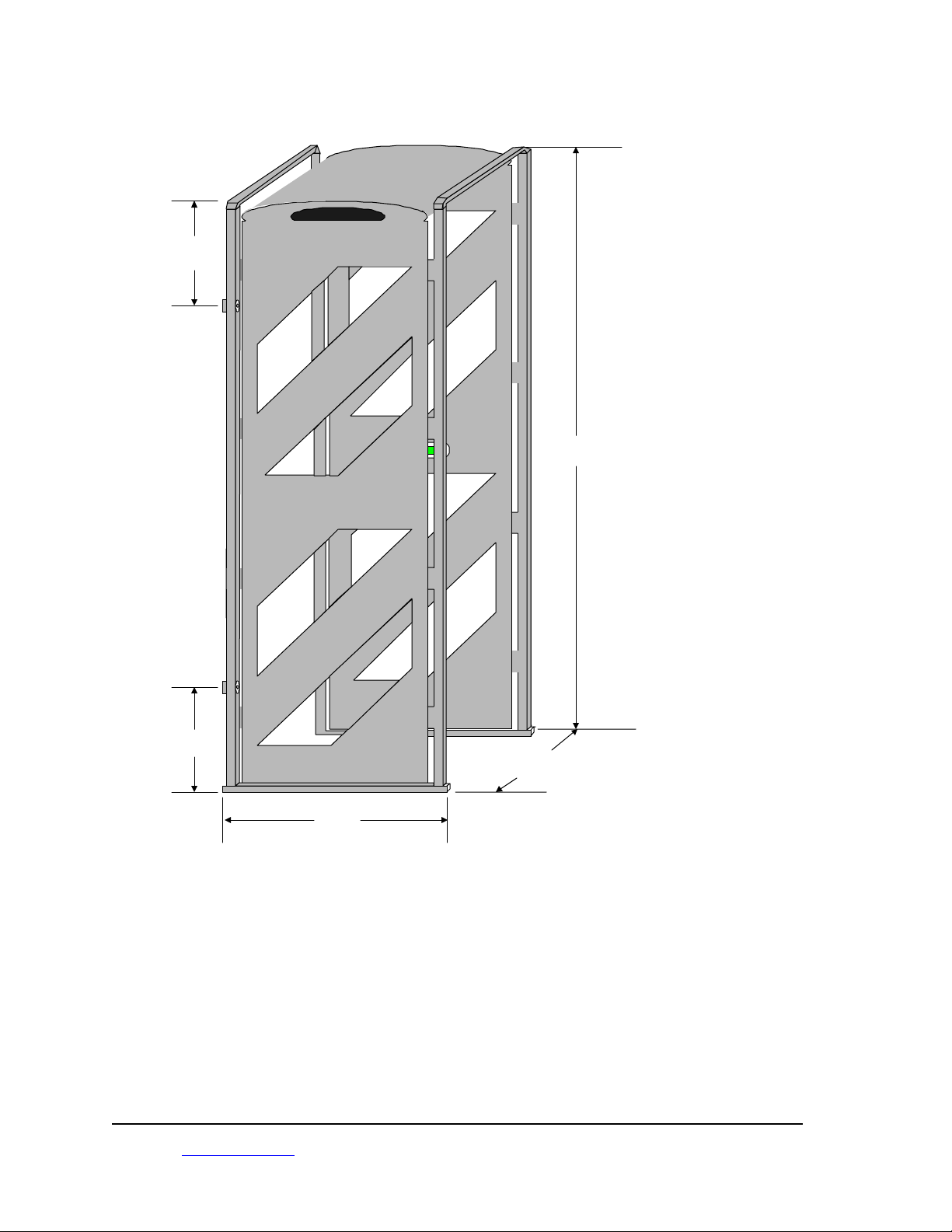
3.2 AM P 100 P ortal Reader Dimensions wit h mounting points
19"
HID
ProxTra
k ID
89"
19"
40.5"
38"
_________________________________________________________________________________________
HID Corporation 9292 J eronimo Road Irvine, CA 92618 USA T EL ( 949) 598- 1600 ( 800) 237- 7769 FAX (949) 598- 1690
Web page –
www.proxtrak.com
– ProxTrak Port al Reader Installation Procedure 6042-901-01 Rev 7
6 of 32
Page 8

3.3 M echanical Assembly P rocedure
The portal must be assembled in an area where there is at least 96 inches of clearance between the floor
and the ceiling.
Start with the Portal assemblies located near where the Portal will be installed. The portal will be
assembled on one side and then tipped upright. It may then be moved into place.
On each major compo nent there will be a r e d d ot indicating the do o r way s id e or edge.
Support the base perpendicular to the floor with the doorway edge up (the doorway edge is the edge
nearest from the crossover wires embedded in the bottom). Stand the Primary Panel assembly on its
entrance edge (the primary panel assembly is the one with the LCD module), red dot up, and f asten it to
the Threshold assembly with the LCD facing towards t he inside of t he portal. Use 8 of the t aper ed machine
screws, four in each of the corner supports in the uprights. Repeat for the secondary panel assembly.
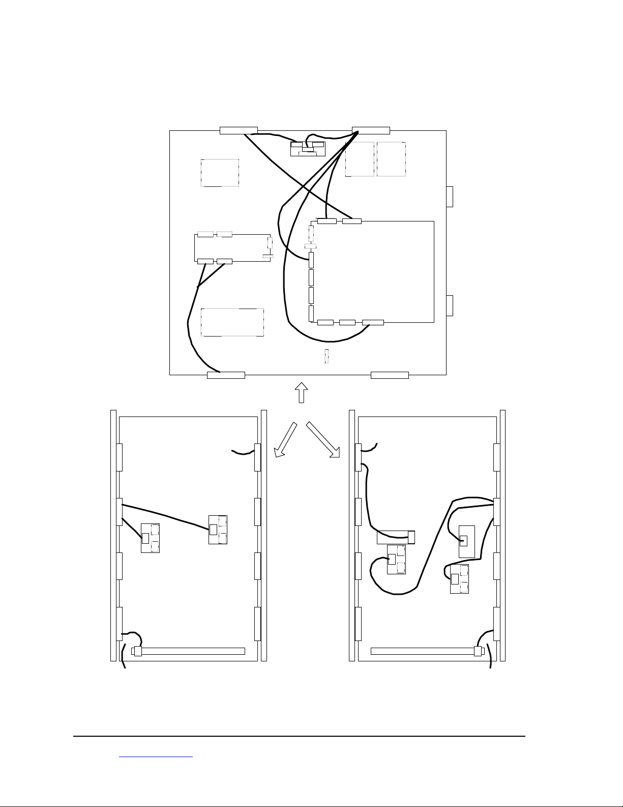
Install cross over tubes and route cables as shown in Figure 1
Note - Use precautions to guard against static discharges to any exposed electronics when
handling the Controller assembly.
Place the Controller assembly on its entrance edge and slide the left and right edges onto the Panel
assemblies gray mounting blocks. Note that the fans are located closest t o the Primary side. Use t he hex
key head 10-20’s (4 each with washers), screw ed into the threaded insert in the controller assembly. Add
the 4 1”, 6-32 pan-heads in the through-holes, with the washer and nut on the top, to each gray brack et .
The Portal can now be stood upright. Be sure to lift t he t op end st r aight up, wit hout str es sing t he Port al by
tilting it to the right or left; lift using the lower gray structural pieces. Do not lift the white antenna
assemblies or the upper gray members. The Portal is not designed to be put into use without structural
support provided at the doorway. ( See “Door f r ame mounting”), below.
_________________________________________________________________________________________
HID Corporation 9292 J eronimo Road Irvine, CA 92618 USA T EL ( 949) 598- 1600 ( 800) 237- 7769 FAX (949) 598- 1690
Web page –
www.proxtrak.com
– ProxTrak Port al Reader Installation Procedure 6042-901-01 Rev 7
7 of 32
Page 9
3.4 Electrical Assembly
3.4.1 Cable Connections
Connect cables as shown.
+ 5VDC
A1-Portal Electronics Assembly
P1P2P3
P4
A3 - Sensor
I/O Bd
- 40VDC +40VDC
P3
P1
P2
Sensors
P4 P7 P8 P9
P1 P1
A2 - Exciter Amplifier
Assembly
P2 P2
P
1
J1
Rcvr-Pri
Power
Exciter
P5
P6
FSK
FSK
Rcvr-Sec
A1 - DSP Bd Assembly
Fan
Fan
I/O
+/- 12VDC
LCDComm I/O
P12P10 P11
Fan Power TB
A3 - Secondary Antenna Panel A2 - Primary Antenna Panel
Exciter
Antenna
Door Side
Exciter
Antenna
P
2
P
1
P
3
Summing Bd
P
1
Exciter
Antenna
P
2
P
1
P
3
A2-Rcvr Antenna
Summing BdA1-Rcvr Antenna
A2-LCD
P
1
P
2
P
1
P
3
A3-Rcvr Antenna
Summing Bd
A5-SensorsA3-Sensors
A1-FSK Rdr
P
1
P
2
P
1
P
3
A4-Rcvr Antenna
Summing Bd
P
1
Exciter
Antenna
_________________________________________________________________________________________
HID Corporation 9292 J eronimo Road Irvine, CA 92618 USA T EL ( 949) 598- 1600 ( 800) 237- 7769 FAX (949) 598- 1690
Web page –
www.proxtrak.com
– ProxTrak Port al Reader Installation Procedure 6042-901-01 Rev 7
8 of 32
Page 10

3.5 Door Frame Mounting
3.5.1 Installation Accessory Kit
Each unit will be s upplied wit h an installa tion acce s s o ry k it cont aining the f o llo wing:
Mounting screws
Mounting washers
Mounting spacers
Cable egress/fit t ing kit
3.5.2 Mechanical Mounting Procedure
The Portal requires a external support structure such as a doorway frame, a structural wall nearby or
external supports designed to support t he Portal f rame from movement caused by incidental forces such
as people, cart s, dollies or other it ems that ma y come into co nta ct w ith the Porta l in gener al use. The
most common method of mounting is attaching the Portal to the doorframe. This method includes
positioning the Portal Reader close to the doorframe, allow ing for a direct mount t o the framework via the
appropriate f as t eners for wood, steel or aluminum.
With this mounting method, t he doorframe must be 35 t o 41 inches inside width f or an effect ive mounting
struct ure . The AC line cor d must not e xit o n t he f a c e o f t he Port al fr a me that will be used for mounting. The
position of the AC cord can be specified at the time of ordering. An example of a doorframe mount is
shown below.
Door frame mount - viewed from the top
Portal Threshold
Washer
Upright
Lag bolt
Spacer
Portal
Uprights
Wall
Upright/door
frame detail
1/2" Spacers
Door Frame
Door
Definition of “exit” and “entrance” - Since the Portal is mostly used as an exit reader, you enter the Por tal
on the end away from t he door, and you exit the Portal at the doorway end. The two uprights that are on
the exit end of the Reader are devoid of cables between in a cer t ain span of 51 inches in the center of t he
vertical dimensions of the Portal. This is the space available for mounting the Port al to the doorfr ame. Lag
bolts, w ashers and the spacers ( See insert) are included with the Accessory kits. The Lag bolts, w asher,
_________________________________________________________________________________________
HID Corporation 9292 J eronimo Road Irvine, CA 92618 USA T EL ( 949) 598- 1600 ( 800) 237- 7769 FAX (949) 598- 1690
Web page –
www.proxtrak.com
– ProxTrak Port al Reader Installation Procedure 6042-901-01 Rev 7
9 of 32
Page 11

spacer combinations (4 each) should be mounted at the 4 mounting locations listed in the Portal picture in
the “Reader dimension drawing”, above.
The inside cover of each of the Panels w ill have to b e re moved to fac ilita te inst alling the lag b olts int o t he
installation holes.
For some installations it may be necessary to r eplace the lag bolts with longer machined bolts, and mount
clear through to the other side of the wall for a more secure mount.
Other Doorw ays may be wider or narrower t han the Port al dimensions. In these cases, t he installations
may require adapter bracket s mounted to the Portal at the 4 locations. These br ackets could t hen be used
for doing an inside mount on the doorway, or outside mounts on the wall.
4. System Checkout and Test
4.1 Power Supply Check
Power up the system and check the system voltages per Table 1
A1-A1 DSP Boa r d A1-A2 Excit er Asse mbly
U1-5 +5 VDC +/- .1 VDC +40 VDC +/- 1 VDC
U1-12 +3.3VDC + / - . 05VDC -40 VDC +/- 1 VDC
U1-18 +2.5VDC + / - . 05VDC
A2-A5 Sensor Bd A3-A3 Sensor Bd
P1-1 +12 VDC +/- .5VDC P1-1 +12 VDC +/- .5VDC
4.2 Exciter Tuning
Procedure to tune exciter and check exciter current
4.3 Receiver Null
Procedure to check receiver antenna nulls and tuning
4.4 System Performance
With the AMT100 included in the accessory kit t est t he read performance of the portal (put in free running
mode and power up). Also check the performance with the access card
5. Installation into an Asset Management System
5.1 Input and Output Signal Information
All cabling into and out of the portal must be shielded type cable, Alpha 129XC or similar. The connectors
must be AMP 6749810 ser ies or an exact replacement.
5.1.1 Serial cable for Host communications
The communication cable is connected to connector P10 on the DSP Bd Assembly. This is a DB-9 s tyle
connector.
5.1.1.1 M aximum Cable Lengths
RS485 4000 feet (1230 meter s)
RS232 150 feet (46 meter s) .
_________________________________________________________________________________________
HID Corporation 9292 J eronimo Road Irvine, CA 92618 USA T EL ( 949) 598- 1600 ( 800) 237- 7769 FAX (949) 598- 1690
Web page –
www.proxtrak.com
– ProxTrak Port al Reader Installation Procedure 6042-901-01 Rev 7
10 of 32
Page 12

5.1.1.2 Communications Pin Assignments
P10 Signal Name
1 RS232 TD (Xmit Data)
2 RS23 2 RD (Rcv Dat a )
3 RS232 Signal Ground
4 RS485+
5 RS4856 RS485 Signal Ground
5.1.2 Relays
Two SPDT dry contact relays are provided for local use. These are controlled by the portal through
commands fr om t he host o r s ett ings in the EEPROM .
P11 Signal Name
1 Relay 1 NC
2 Relay 1 NO
3 Relay 1 Common
4 Relay 2 NC
5 Relay 2 NO
6 Relay 2 Common
Relay Sp e c ifications
Contact arrangement: SPDT (1 for m C)
Contact ratings: DC - 28V@1Amp AC - 120V @ .5A
Contact resistance: 100mΩ max @ 6VDC - 1Amp
Life e xpec tancy: 10 million actuations
UL fileE43203
5.1.3 Wiegand Interface
P8 Signal Name
1 Data 0
2 Data 1
4 Signal Return
5 Gr een LED
6 Red LED
7 Beeper
The ProxTrak Reader Wiegand specifications HID P/N 0200-635 is available upon request for t hose users
who require the Wiegand format.
5.1.4 Second FSK Reader
If a sec ond or outside reader is required please contact HID Technical Support for f urther information.
_________________________________________________________________________________________
HID Corporation 9292 J eronimo Road Irvine, CA 92618 USA T EL ( 949) 598- 1600 ( 800) 237- 7769 FAX (949) 598- 1690
Web page –
www.proxtrak.com
– ProxTrak Port al Reader Installation Procedure 6042-901-01 Rev 7
11 of 32
Page 13

6. Setup and Configura ti on
6.1 Con f igurati on Jumpers on t he DSP Cont roller Board
Caution: P ow er must be off an d Stat ic protect ion must be used w hen changi ng
any j ump er or sw itch set t ings.
2 pin jumper locations Description
P2-7 to 8 Boot mode – normal (always in)
P2-1 to 2 Boot mode – must be removed for normal boot mode
P2-3 to 4 Boot mode – must be removed for normal boot mode
P15-4 to 6 RS232 selected (2 to 4 w ould be RS485)
P15-3 to 5 RS232 selected (1 to 3 w ould be RS485)
P23-2 to 3 Beeper enabled (Move to connect 1 and 2 to disable
P28-2 to 3 RS485 terminating resistor – in for end of the line
termination (last r eader )
P46-1 to 2 Flash programming enable. Move to connect 3 and 4 to
disable Flash programming. Default – 3 t o 4
6.2 Serial Communication
The communication channel to the Host is provided via RS485 or RS232, selectable by jumpers on the
DSP Contr o l Bo ard.
6.2.1 RS485
The RS485 option is the default sett ing, since it is capable of multi-drop points and can be connected at
long cable distances. The interface defaults to 19,200 baud, 1 stop, 8 data bits and no parity. Other
selections are 4800, 9600 and 38,400 baud.
The RS485 configuration is selected by placing 2 jumpers on the DSP Control Board. See the
“Configuration Jumpers” section for details.
For RS485, a 2 wire interfac e is supported - use 485+ and 485- . Shield should be connected to only one
end (master end – Host or panel). For 2 wire 485, each device must have a proper earth ground for
proper communications operation.
For 3 wire 485 - If a third wire is used for a Signal return, use a 100 ohm, ¼ Watt r esistor t o Pin 6 of the
above table, to limit ground fault currents.
6.2.2 RS232
The RS232 option works identically to the RS485, with the exception of the hardware limits; no multi-drop
and the cable distance is limited. There are no diff erences in the firmware or soft ware r equirements of t he
protocol. The RS232 configuration is selected by placing 2 jumpers on the DSP Control Boar d. See t he
“Configuration Jumpers section”.
A 3 wire RS232 interface is supported – Use TD, RD and Signal ground.
6.2.3 RS485 and RS232 Connector Terminal Assignments
P10 Signal Name
1 RS232 TD (Xmit Data)
2 RS 232 RD (Rcv Data)
3 RS232 Signal Ground
4 RS485+
5 RS4856 RS485 Signal Ground
_________________________________________________________________________________________
HID Corporation 9292 J eronimo Road Irvine, CA 92618 USA T EL ( 949) 598- 1600 ( 800) 237- 7769 FAX (949) 598- 1690
Web page –
www.proxtrak.com
– ProxTrak Port al Reader Installation Procedure 6042-901-01 Rev 7
12 of 32
Page 14

6.2.4 Baud Rate and Node Address
Selection of the baud rate and node address for multi-drop communication is done on Switch 7. See the
Switch settings section for details.
6.3 Polled mode
See the ProxTrak M ulti-Drop Serial Protocol (Document number 0200- 636) for a complete description of
the Commands from the Host, Messages from the Reader, packet formats, and suggested Polled
operation. This Protocol uses a binary formatted packet that minimizes transaction overhead and
maximizes speed while providing a multi-point communication pathway.
6.4 Simplex mode
There is a Simplex mode, which allows the use of a general purpose Serial communication utility for
connecting to the Reader. This is a simple way t o get Reader dat a that only requires a one way interface.
There is an initial star t-up message t hat puts out status information, and t hen ID information is s ent out
when Access cards and or Asset tags have been acquired. This is an ASCII interface and it will w ork wit h
either RS232 or RS485 for test ing with one Host and one Reader. To turn on t he Simplex mode, Turn on
Swit ch 7, posit ion 1. Also, since po lling fro m the Host is not r ecommended in Simplex mode, use t he fr eer unni ng m ode set t ing of the switches, Sw itc h 8, position 3, On.
6.5 LCD interface
The LCD interface is used for sending messages to t he user of the Por tal. If t he Reader is in the def ault
mode, the messages will need to be sent fr om the host to t he Reader using the Send Message to Display
command. In the LCD Test mode, Access cards I D's and the Asset t ag Count will be dis played. The Tag
count is a number t hat is incremented fr om 1 to 5 when additional Asset I D's are acquired. The count is
reset when an Access card is read. Turn Switch 6, Position 7 - ON to turn on the test mode.
6.6 Tag Command options
The communication protocol required is the HID “ProxTrak Multi-Drop Serial Protocol” and should be
refer enced when developing applications with the Portal Reader.
The Asset tags require communication from the Reader to f acilit at e select ing the tag, a cquiring t ag I D dat a
and setting the Tamper bit and subsequently shutting down the tag to allow ot her t ags t o be available for
acquisition. There are several options available to the user that can be used to facilitate getting these
commands t o t he tag q uickly and w ith fle xibility. There are Aut omat ic Tag commands and Host contr olled
Tag commands. There is also a version of t he Automatic Tag command function called the Failsafe mode
that is activated automatically if t he communication to the Reader fr om the Host is interrupted.
6.6.1 Default T ag commands
Default Tag commands are programmable in EEPROM. When the Reader resets or after power-up, it
reads the EEPROM to f ind out w hich command or sequence of commands it s hould send to the T ag every
time it acquires a new Tag ID. The normal default tag command is a Set Quiet command. This can be
changed to include the Set Tamper command. See the AT24RF08 command descriptions in the Atmel
specification.
6.6.2 Failsafe Tag commands
The Failsafe feature allows the user to change the Default Tag Command setting to be a new Tag
command in the event that t he communication fails between the Reader and the Host. Aft er a f ixed delay
(default is 30 seconds, progr ammable) from the last host command, the Failsafe Tag Command goes into
effect. I f the Reader has sw itc hed to the failsafe mode due to communication problems, the first successful
poll will have a bit set in the Tag ID mes sage, alert ing the Host that the failure has occurred since the last
successful poll.
6.6.3 Host controlled T ag commands
The Set Tag Command can be sent from the Host to override the current Default Tag command. The
Reader accepts the Set Tag Command fr om the Host and replaces the current default Tag command. It
will pe rf o r m the new t a g c o mmand on every new ly a c quir ed tag indef init e ly until a new Set Ta g Command,
reset or power cycle.
_________________________________________________________________________________________
HID Corporation 9292 J eronimo Road Irvine, CA 92618 U SA TEL ( 949) 598- 1600 ( 800) 237- 7769 FAX (949) 598- 1690
Web page –
www.proxtrak.com
– ProxTrak Port al Reader Installation Procedure 6042-901-01 Rev 7
13 of 32
Page 15

6.6.3.1 Individual ProxTrakTM Comma n ds
Host commands can be sent to a specific Asset I D t ag. W hen the I D has been acquired and t r ansferr ed t o
the Host d uring t he norma l po lling proce s s , t he Host c an t hen send an Individual Tag command to Pr o xTr a k
Tag, based on the ID. The Reader accepts the Individual Tag command(s) f rom t he Host and sends it t o
the tag if currently available in the field. If the tag is not currently in the field, the Reader sends a failure
response to the Host after a 1-second timeout.
6.6.3.2 Global ProxTrakTM Comma n ds
Host commands can be sent globally to Asset ID tags by sending Global Tag Command, which contains
the specific tag command. The Reader accepts t he Global Tag c ommand from t he Host and sends it t o all
tags that are c urrently available in the field.
Refer to the ProxTrak Multi-Drop Serial protocol specif ication for a complete description of the Set Tag
command, Individual Tag command, Global Tag command and EEPRO M locations f or set ting the Default
Tag command and the Failsafe tag command.
6.7 Indicators
Indicators include the Red/Green LED, Beeper, Relay 1 and Relay 2. Each indicator also has its own
programmable duration setting. Some default indicator act ions are pre-programmed for Pow er up, Access
card read, Asset card read and when a Tag Command has been sent to ProxTrak tags. These default
actions can be changed during the Portal set- up. I f these default act ions are not sufficient, the Indicator
command can be used. This command can be sent at any time from the Host, over-riding any current
actions. Refer t o the ProxTrakTM Serial Protocol. Each Indicator has a list of up to 32 specific sequences,
including individual flash, flash twice, flash three times, cycle on/off, etc.
6.7.1 Red/Gr een LED and Beeper in the Access control Reader
The Red/Green LED and beeper is located on the face of the ThinLineTM reader, and will activate using
the default actions listed in the indicator actions and respond to t he Indicator command.
6.7.2 Red/Gr een LED and Beeper located on the DSP contr oller electronics.
There is Red/Gr een LED and beeper located on the Controller electronics of the Portal reader , and will
activate using the default actions listed in the indicator act ions and respond to t he Indicator command. This
internal Beeper has a jumper for disabling/enabling the feature. Refer t o the Jumper settings. The beeper
can be disabled by moving jumper P23 to connect pins 1 and 2.
6.7.3 Relay 1 and Relay 2
The Relays are locat ed on the PCB and have connections available to select t he normally open or normally
closed terminals. They can be included in the default indicator actions and can be activated with the
Indicator command. See the terminal strip connections available in the cabling requirements sect ion.
6.8 EEPROM Con fi g u ration i n fo rmation
Refer to the EEPROM configuration table, below and in the in the ProxTrakTM Serial Protocol for the
memory locations that set the following configurable features of the Reader. The EEPROM can be
changed and tested by using t he W r ite EEPRO M and Read EEPRO M co mmands – also desc ribed in the
Protocol specification. Test software that provides an easy user interface is provided with each Portal
Reader. Refer t o the ProxTrak Utilit ie s User s Manual for more inf ormat io n.
6.8.1 Indicators (LED's, Beeper, Relays) duration's
All five indicators have a 1 byte value. The byte specif ies the basic duration used by t he Reader to act ivate
the indicators. Refer to the table of I ndicator act ions, below. The references to long, medium and short
flashes (beeps, clicks) are based on this duration.
The default indicator duration bytes factor y defaults are programmed as follows ( 100mSec/count):
Indicator Byte Value (HEX) Duration
Red LED 10 1.6 Sec
Green LED 10 1.6 Sec
Beeper 10 1. 6 Sec
Relay 1 10 1.6 Se c
Relay 2 10 1.6 Se c
_________________________________________________________________________________________
HID Corporation 9292 J eronimo Road Irvine, CA 92618 U SA TEL ( 949) 598- 1600 ( 800) 237- 7769 FAX (949) 598- 1690
Web page –
www.proxtrak.com
– ProxTrak Port al Reader Installation Procedure 6042-901-01 Rev 7
14 of 32
Page 16

Note: To use the table defaults for an example; a duration of 1.6Sec; Long = 1.6Sec, Medium = . 4Sec,
Short = .1Sec. Also, if the Indicator duration is switched to "Fast" (see switch settings), all duration's will
be 4 times shorter than the default (in the above example, Long w ould become . 4 sec, medium, 100mSec,
and short, 25mSec). Up to 32 actions can be specified for each device, except Relay 2, which has 16
actions.
6.8.2 Programmable indicator r esponses on major events
There are 3 bytes for each major event to define the indicator actions. The events include Power-up,
Access Card read, Asset Tag r ead and an Individual Tag Command has been executed.
Default settings for Events 3 byte Indicator Command (HEX) In dicator Descriptions
Extra bits/RederGreen/BeepergbRelay1/Relay2
r1r2
Power up default E4 55 00 Two Med Red Flashes off, Two Med
Acc ess Ta g rea d 02 25 88 Short Red Fla sh off, Short Gree n Fla sh
Pro xTrak Ass et Tag read 02 33 88 Short Red Fla sh off, Short Gree n Fla sh
Tag operation performed
(other than Set Quiet)
AC 0D 88 Three Med Red Flashes off, Three
Green Flashes on, Two Med Beep on,
Relays off
off, Med Beep on, Rel ays n o chan ge
on, Short Beep on , Relays n o chan ge
Green Med Flashes on, Three Med
Beeps, Rel ays n o chan ge
6.8.3 Default tag command
This setting programs the Tag command that will be used for each Asset Tag in the field. The factory
default is a Set Quiet command.
6.8.4 Failsafe activation timeout
Specifies how long the Reader waits from power up without Host Comm or after the absence of Host
communication to switch the Automatic Tag command over to the Fail safe Tag command.
6.8.5 Failsafe tag command
This setting programs the Tag commands that the Reader w ill use if the communication t o the Host has
been interrupted for a time equal to the Failsafe activation timeout. The factory default is a Set Quiet
command.
6.8.6 Multiple Adjacent Unit Interface (M aui)
Maui is a scheme for 125kHz detection and anti-collision used in the ProxTrak Portal Reader. It is a
method of handling 125KHz interf er ence for multiple readers by waiting for t he interference to go away and
resuming wit h normal operation, intersper sing their on times in an orderly fashion; if 2 Readers are close
enough to det e c t eac h ot her , t hey will sy nchronize by alternating t heir e xciter cycles to avoid interference.
6.9 Wiegand Output
Refer to the Wiegand specification for t he complete description of the Wiegand output formats.
A 26 bit format is generated f or Asset ID’s acquired by the Portal Reader. The 26 bit format sends an 8 bit
Facility c ode and 16 bit “card data” enclosed in parity bit s f or err or detec t ion. 2 f or mats are supported. An
IBM tag type is supported by parsing part of the Manufact uring code, and including it in the “card dat a”. A
Legacy tag t ype is supported t hat sends the least significant 16 bits of t he legacy data as t he “card dat a” .
For Access cards (and fobs) the data is passed from the card to the output directly, making the system
compatible for 26, 35, 37bit et c. bit for mat s.
6.10 Dow nload new Acquisit ion Pro cessor (AP) code
Refer t o the Download instructions found with the ProxTrak
Reader.
_________________________________________________________________________________________
HID Corporation 9292 J eronimo Road Irvine, CA 92618 U SA TEL ( 949) 598- 1600 ( 800) 237- 7769 FAX (949) 598- 1690
Web page –
www.proxtrak.com
– ProxTrak Port al Reader Installation Procedure 6042-901-01 Rev 7
TM
Utilities sof tw ar e, included wit h ea ch Po rt al
15 of 32
Page 17

6.11 Diagnostics
6.11.1 Set Calibration command
The Reader performs an auto-c alibrate of all receivers and returns a Calibration response, which includes
the Exciter phase value.
6.11.2 Status Request Command
The Reader responds with a Data block message w hich includes the Status byte and a noise byte. The
Status byte includes information about the last acquisition status and a set of err or codes. The noise byte
is an indication of the number of transitions in the receiver cycle during the highest exciter level and the
most significant bit represents an alert that the MAUI delays had to be activated as a result of an
interfering 125kHz interf er ence.
6.11.3 H/W Configuration
The Hardware configuration command tests the switch blocks and returns switch settings in the H/W
Configuration response message.
6.11.4 Reset Command
Sending a $0D command resets the Reader.
_________________________________________________________________________________________
HID Corporation 9292 J eronimo Road Irvine, CA 92618 U SA TEL ( 949) 598- 1600 ( 800) 237- 7769 FAX (949) 598- 1690
Web page –
www.proxtrak.com
– ProxTrak Port al Reader Installation Procedure 6042-901-01 Rev 7
16 of 32
Page 18

7. Tables – Switc h se ttings, E EPROM Settings and Indicator actions
Switch Settings - Caution: Power must be off and Static protection must be used when changing these
switches.
7.1 Acqu isit ion Pro cessor switch es
Note: In general the acquisition switches are factory and troubleshooting settings only – the Main
configuration changes are done on the Communication section Switches – Switch 6, 7, 8 and 9, shown
below.
Switc h 2
1. De-multiplexed data capture Channel (Receiver) 1
2. De-multiplexed data capture Channel (Receiver) 2
3. De-multiplexed data capture Channel (Receiver) 3
4. De-multiplexed data capture Channel (Receiver) 4
5. Header capture If O n, F/W allows Header fr om str ongest channel to be at 0x80008000
6. ID Capture If On, F/W allows next ID from the strongest channel to be at 0x80008000
7. Skip auto-null If On, skips auto-null at power-up
8. Spare Not used
– Acquisition tes ting
Switc h 3
– Acquisition testing (continued)
1. Miller code generator If On, generates a Miller cod e d tag number f o r de-bugging purpo s e s
2. Checksum validation If On, Reader requires a checksum for validating Asset tags
3. A/D loop-back If On, Reader generates an data str eam for t he digital filtering algorithms
4. Disable Dynamic Auto- null If On, Disables the dynamic auto-null
5. Run Mode If On, Forces CP Run mode ("RN" on LED's)
6. Programming mode If On, no programming on power-up, normal operating mode ("FL") on
LED's
7. Skip FSK Reader Along with switch 8 (Lsbit), it is t he number of cycles skipped f or t he FSK mode
After a successful Access read.
8. Skip FSK Reader Along with switch 7 (Msbit), it is the number of cycles skipped for the FSK
mode, after a successf ul Access read.
Switc h 4
– Acquisition testing (continued)
1. Force I phase If O n, Acquisition is always on I phase
2. Force Q phase If O n, Acquisition is always on Q phase
3. 180 degree phase shift If On, data is shifted 180 degr ees
4. Daughter boar d t y pe Off for current daughter board
5. Daughter boar d t y pe Off for current daughter board
6. Daughter boar d t y pe Off for current daughter board
7. Daughter boar d t y pe Off for current daughter board
8. Daughter boar d t y pe Off for current daughter board
Switc h 5
– Acquisition testing (continued)
1. Filter Setting If On, Band-pass filter ( Used for 2D systems
2. ID averaging Along with switch 3, it is 2-to-t he-nth ID's that are averaged (Lsbit)
3. ID averaging Along with switch 2, it is 2-to-t he-nth ID's that are averaged (Msbit )
4. Channel for Maui detection Along with switch 5, receiver used for Maui (LSBit)
5. Channel for Maui detection Along with switch 4, receiver used for Maui (MSBit)
6. Maui enable I f On, Maui enabled
7. Force Maui threshold If On, Sets Maui threshold to 0x40
8. Single Tag Mode If O n, Only one Asset r ead per cycle to improve speed
_________________________________________________________________________________________
HID Corporation 9292 J eronimo Road Irvine, CA 92618 U SA TEL ( 949) 598- 1600 ( 800) 237- 7769 FAX (949) 598- 1690
Web page –
www.proxtrak.com
– ProxTrak Port al Reader Installation Procedure 6042-901-01 Rev 7
17 of 32
Page 19

7.2 Commu nicat ion Pro cessor Sw itch es:
Switc h 6
1. Set Tamper Latch Mode If On, set tamper latch bit. If off, Set Quiet bit.
2. Re-Report If On, Tag ID’s are always reported. If off only new tag ID’s are
3. Indicator r e- r epor t s If O n, I ndicators r epor t f or every t ag. I f off only new tags are reported
4. Fast Indicator duration If On, indicators are 4X faster than default duration’s.
5. Acquisition test reports If On, Sends receiver and power level reports on serial port. (If switch
6. Spare Not used
7. LCD test mode If On, LCD report s I D and sensor messages, off is Host control of LCD
8. Test LCD type If On, LCD is single line, off is dual line
– Read, Report modes
reported
block swit ch 7 is on LCD w ill be updated ) Simplex always r esponds with
test data.
Switc h 7
– Serial Settings (all off)
1. Simplex serial output (On, off) If On, Simplex Serial output
2. Baud Rate On -- 4800 O n -- 9600 Off -- 38,400 Off -- 19,200
3. Baud Rate On – 4800 Off – 9600 On – 38,400 Off – 19,200
4. Node address, Bit 0 On = 1 Off = 0
5. Node address, Bit 1 On = 1 Off = 0
6. Node address, Bit 2 On = 1 Off = 0
7. Node address, Bit 3 On = 1 Off = 0
8. Node address, Bit 4 On = 1 Off = 0
Note: Data is always 8 bits, no parity, 1 st op bit
Switc h 8
– Hardware options and test modes
1. MaxiTrak mode If On, Firmw are is put in MaxiTrak Mode
2. FSK Exciter If On, Uses the same exciter for access and assets
3. Free R unning I f On, Ac qui si tio n i s free-runni ng regardless of Host polls
4. Output Port If On, LED port switches to an output port, Off is not used
5. Hardware demod. for FSK If On, FSK data has been demodulated in h/w, if off, firmware must
demodulate raw data.
6. Spare Not used
7. Spare Not used
8. Spare Not used
Switc h 9
– Initialization and overrides
1. Switch Over-ride (On, off) If On, firmware disregards all switches and uses EEPROM
2. Res et t o Fa c t o r y d efaults ( On, of f) If O n, a t power-up, EEPRO M is s et t o firmw a r e values
3. EEPRO M unlock (O n, off ) If On, allow wr it e s t o r e s erved EEPROM a r e a
4. Flash Mode bit 0 Not used
5. Flash Mode bit 1 Not used
6. Spare
7. Spare
8. Set Wiegand Facility co de I f On, Unit re sets a nd as signs the fac ility cod e of the next read Acces s
card to an EEPROM location. This FAC code will be inserted into all
Wiegand messages.
Other System Swit ches:
Switch 1 - Reset switch
Switch 10 - Vandal switch
Switch 11 - Presence simulator sw itch
Switch 12- Exit simulator swit c h
_________________________________________________________________________________________
HID Corporation 9292 J eronimo Road Irvine, CA 92618 U SA TEL ( 949) 598- 1600 ( 800) 237- 7769 FAX (949) 598- 1690
Web page –
www.proxtrak.com
– ProxTrak Port al Reader Installation Procedure 6042-901-01 Rev 7
18 of 32
Page 20

Switch 13 - Calibrat io n initiation sw itch
_________________________________________________________________________________________
HID Corporation 9292 J eronimo Road Irvine, CA 92618 U SA TEL ( 949) 598- 1600 ( 800) 237- 7769 FAX (949) 598- 1690
Web page –
www.proxtrak.com
– ProxTrak Port al Reader Installation Procedure 6042-901-01 Rev 7
19 of 32
Page 21

7.3 EEPROM Memory map table
Hex Dec Name Description Default
$00 - $27 000 -
039
$28 040 Red Red LED Duration byte $10 - 1.6 Sec (.4 Sec if
$29 041 Green Green LED Duration Byte $10 - 1.6 Sec (.4 Sec if
$2A 042 Beeper Beeper Duration Byte $10 - 1.6 Sec (.4 Sec if
$2B 043 Relay1 Relay 1 Duration Byte $10 - 1.6 Sec (.4 Sec if
$2C 044 Relay2 Relay 2 Duration Byte $10 - 1.6 Sec (.4 Sec if
$2D 045 Reserved
$2E 046 Reserved
$2F 047 Failsafe
$30 - $32 048 -
050
$33 - $35 051 -
053
$36 - $38 054 -
056
$39 - $3B 057 -
059
$3C - $44 060 -
068
$45 069 Switch Block
$46 070 Switch Block
_________________________________________________________________________________________
HID Corporation 9292 J eronimo Road Irvine, CA 92618 U SA TEL ( 949) 598- 1600 ( 800) 237- 7769 FAX (949) 598- 1690
Web page –
www.proxtrak.com
FT 40 Reser ved, 32 used, 8 spare Fact or y table - Exciter
"fast" switch is on)
"fast" switch is on)
"fast" switch is on)
"fast" switch is on)
"fast" switch is on)
activation
Number of seconds befor e Failsafe
activation after Comm failure
$1E - 30 Sec o nds
time
Power up
Indicator
3 bytes to describe the indicator
status on Power-up
$E4 $55 $00; Two M ed Red
Flashes off, Two Med Green
Flashes on, Two M ed Beeps
on, Relay s o ff
Access read
indicator
3 bytes to describe the indicator
action on an Access Control Read
$02 $23 $88; Short Red
Flash off, Short Green Flash
off, Med Beep on, Relays no
change
ProxTrak
read Indicator
3 bytes to describe the indicator
action on an Asset tag Read
$02 $33 $88; Short Red
Flash off, Short Green Flash
on, Short Beep on, Relays
no change
Host Tag
command
performed
3 bytes to describe the indicator
action when a ProxTrak command
has been executed fr om t he Host
$AC $0D $88; Three Med
Red Flashes off, Three
Green Med Flashes on,
Three Med Beeps, Relays
no change
9 Reserved, 0 used Spares
2 Read and
Report
b0: Set Tamper Latch (Disable
Assets mode) on
b1: Re-repor t ID's
$00; Read and Report
options - (Mirror of Switch
Block 2)
b2: Indicator re-report
b3: Fast indicators
b4: Acquisition test r epor t s
b5: EEP d atabase
b6: LCD report s
b7: Te s t LCD inst a lle d
3 Serial
Configuration
b0: Simplex Serial Output
(1 = on, 0 = Off)
b2 - b1: Baud Rate
$00; Serial Configuration;
(Mirror of Switch Block 3)
11 = 4800 01 = 9600
10 = 38,400 00 = 19, 200
b7 - b3: Node Address
(00000 - 11111)
– ProxTrak Port al Reader Installation Procedure 6042-901-01 Rev 7
20 of 32
Page 22

$47 071 Switch Block
4 Hardware
and Test
Options
b0: ProxTrak mode
b1: Access control exciter
b2: Asynchronous acquisition
b3: Stat us LED's disable
$00; Hardware and Test
Options; (Mirror of Switch
Block 4)
b4: H/W demodulator
b5: Low gain
b6: 8 receivers
b7: 2nd Access Reader
$48 072 FT Not used Spare
$49 073 Failsafe Tag
Command
Failsafe Tag Command Size (1
byte)
$01
Size
$4A - $5B 074 -
091
$5C 092 Default Tag
Failsafe Tag
Command
Failsafe Tag Command Byte(s) $16; (Set Quiet bit
command)
Tag Command Size (1 byte) $01
Command
Size
$5D - $6E 093 -
110
$6F 111 Response
Default Tag
Command
Timeout
Tag Command Byte(s) $16; (Set Quiet bit
command)
Reader sends Nothing to Send or
$0B; (1 second)
empty Tag ID Message (0 to 23
seconds)
$70 112 Maui Timeout Reader activates cycle if Maui
$46; (700mS)
threshold has been exceeded for
this time ( 0 to 25.5 seconds)
$71 113 Maui
Threshold
$72 - $7F 114 -
FT 14 Reser ved, 10 used Factory t able - Timing and
127
Level required by the interferer to
activate Maui delays (0 to 255)
$FF; ($FF causes Maui to
be disabled)
calibrat io n values
_________________________________________________________________________________________
HID Corporation 9292 J eronimo Road Irvine, CA 92618 U SA TEL ( 949) 598- 1600 ( 800) 237- 7769 FAX (949) 598- 1690
Web page –
www.proxtrak.com
– ProxTrak Port al Reader Installation Procedure 6042-901-01 Rev 7
21 of 32
Page 23

7.4 Indicator actions
Extra
Bit
0 0000 0 OFF
0 0001 1 ON
0 0010
0 0011
0 1010
0 1011
0 1000 8 No change for t hat indicator This action allows commands to be sent t o
0 1001 9 Spare
1 0000 0 Spare
1 0001 1 Spare
1 0010
1 0011
1 1000 8 No change for t hat indicator This action allows commands to be sent t o
1 1001 9 Spare
1 1010
1 1011
The Actions above apply to Red LED, Green LED, Beeper, Relay 1 and Relay 2. “Flash(es)” is to be
interpreted as “flash(es)”, “ beep( s) ” or “ click( s) ” , as appr opr iate.
Actio
n#
Nibbl
e
0100
0110
0101
0111
1100
1110
1101
1111
0100
0110
0101
0111
1100
1110
1101
1111
Action
#
(Hex)
2
4
6
3
5
7
A
C
E
B
D
F
2
4
6
3
5
7
A
C
E
B
D
F
Act ion Des c r ip tion Comments
Short Flash OFF
Medium Flash OFF
Flash Duration set in “Set configuration”, or
defaults to 1.6Sec on Power- up
Long Flash OFF
Short Flash ON
Medium Flash ON
Long Flash ON
Short Flash Cycle OFF/ ON
Medium Flash Cycle OFF/ON
Long Flash Cycle OFF/ON
Short Flash Cycle ON/OFF
Medium Flash Cycle ON/O FF
Long Flash Cycle ON/OFF
Short = 1/16t h Durat ion
Medium = ¼ Duration
Long = Duration
The Cycle action can be used to alternate Red
and Green if used in the same indicator
command.
Cycle action toggles device indefinitely at
Duration rate. Note - ON/OFF or OFF/ON
indicate st ar t /stop s t at e.
other indicator(s), without effecting the current
status of t he indicator f or which it is used.
TWO Short Flashes OFF
TWO M edium Flashes OFF
TWO Long Flashes
The extra bit allows special actions; in this
case, two flashes can be activated with one
indicator command.
TWO Short Flashes ON
TWO M edium Flashes ON
TWO Long Flashes ON
other indicator(s), without effecting the current
status of t he indicator f or which it is used.
THREE Short F las hes O FF
THREE Medium Flashes OFF
THREE Long Flashes OFF
The extra bit allows special actions; in this
case, t hree flashes can be activated with one
indicator command.
THREE Short F las hes O N
THREE Medium Flashes ON
THREE Long Flashes ON
_________________________________________________________________________________________
HID Corporation 9292 J eronimo Road Irvine, CA 92618 U SA TEL ( 949) 598- 1600 ( 800) 237- 7769 FAX (949) 598- 1690
Web page –
www.proxtrak.com
– ProxTrak Port al Reader Installation Procedure 6042-901-01 Rev 7
22 of 32
Page 24

8. Portal Functional Description
The ProxTrak Port al Reader integrat es t he Access control and Asset control functions in the same Reader,
styled in a fashion resembling a styled metal detector at the airport. The combination of Access and Asset
contr ols, wit h the abilit y to t rack p resence o f individuals, crea tes a p ower ful Reader t hat can be used to
expand the capability o f t he tr adit ional Acce ss c ontro l system to include Asset tracking and management.
The doorway sized unit enables the integrat or to pursue hands-free Asset contr ol, increasing throughput,
reducing paperwor k , and bring asset management to a new level of tr ac eability and ea s e of use.
The Access control feature is a reader similar to our popular ThinLineTM Product, integrated as a
presentation style reader so t hat tailgating and other act ivity around the Portal can be closely monitored.
8.1 Operating Cycle
Upon power up and during operation, the Reader performs various self-diagnostic and optimization
operations. Messages from this process are sent to the host (if requested). See the Protocol Spec for
more information.
After initialization, the Reader responds to polls from the host by starting a scanning cycle, or in freerunning mode, periodically steps through the scanning sequence by searching for Access or Asset tag
data. Bef ore star ting the scanning sequence the Reader detects interfer ing 125kHz equipment. I n a mode
called Maui (M ultiple Adjacent Unit Interf ace), if a 125KHz source above a threshold power is detected, t he
Reader waits for a quasi-random interval before another attempt. This process allows the Reader t o get in
sync with another Reader that is close enough to be detected, and get successful acquisitions when
traditional Reader technologies would not.
If an Asset or Access tag is detected, its identification is transmitted to the host as described in the
Protocol Specification. The Reader acquires the information regarding Asset and Access tags and the
entrance and exit sensors, and passes them along to t he host.
The decisions regarding interpretat ion of the data and the resulting actions, are implemented by t he system
integrator.
8.2 RFID Tag and card types
8.2.1 Asset tags
The ProxTrak Port al Reader will per form t ransact ions wit h any Asse t ID compatib le Asset tag including
the HID AMT100 Asset M anagement Tag and Asset ID source tags in IBM c omputers. Read area is
within the full volume of the Portal. The Reader outputs a 12 byte ID string imbedded in the "TAG ID
message". Asset I D is a regist er ed t r ademark of IBM PC Company.
8.2.1. 1 Asset tag types
The system is designed to read up to 5 Asset tags within its range. The Multi-Tag technology has been
developed by Atmel Corp and as a result, there are 8 t ag types available. Any tag t hat is programmed will
be one of the eig ht tag typ es . I f up to 5 diff e rent tag typ es a re in the r a nge of the read e r , they w ill be re a d
successfully. I f t ags that are the same tag type ar e present in the field, t he Atmel design results in timing
collisio ns, a nd t he r ead per formance is reduced.
8.2.2 Access cards
The ProxTrak Port al Reader will read HID ProxCard Access cards, Pr oxKey FOBs and IsoPr ox car dse.
The Reader outputs a 6 byte I D st r ing imbedded in the "Tag ID message"..
_________________________________________________________________________________________
HID Corporation 9292 J eronimo Road Irvine, CA 92618 U SA TEL ( 949) 598- 1600 ( 800) 237- 7769 FAX (949) 598- 1690
Web page –
www.proxtrak.com
– ProxTrak Port al Reader Installation Procedure 6042-901-01 Rev 7
23 of 32
Page 25

8.3 Acquisition functions
The acquisition cycle of the ProxTrak Portal Reader begins either by the recept ion of a Poll ( or indicator
co mma nd) fr om t he Ho st or if in “F re e r unning ” mode it w ill cycle independently of the Host. See Switch
Settings.
8.3.1 Asset tag Reception
Multi-tag algorithm - Up to five Asset tags c an be acquired at a given moment. The acquisition of Asset
tags requires that the receiver and exciter work in conjunction to receive the Asset tag header, send the
acknowledge modulation, receive the data from a selected tag, and send the appropriate command
modulation back to the tag. Refer t o the Atmel AT24RF08 description for a complete specification, stat e
diagram and Asset t ag features.
8.3.2 Access Card Opt ions
The port al w ill oper ate in one of two modes t o read access cards, “ Presentat ion Mode” or “ Hands Free
Mode”. The modes are selected w ith switc hes, see t he Switch Settings section for details.
8.3.2.1 Present at ion Access Control Reader
The Access control function is similar to a traditional HID family of proximity Readers, such as the
ThinLineTM Reader. Access data is collected by time division multiplexing the Access function with the
Asset tag reading function. The data from the Access cards is put into a 6 byte field in the Tag ID
Message to be c ommunicated t o the Host via the serial port. Note the LED and beeper in the ThinLine
reader ar e used as programmable indicators.
8.3.2. 2 Hands Free Access Card Reader
In this mode the portal will read a HID ProxCard when a person enters t he portal. The card does not have
to be presented to a reader or specific location within or near the portal. This allows a user to pass
through the portal without having to pause or present his access card.
TM
8.3.3 Exciter
8.3.3. 1 125kHz exciter description
The excitation for Asset tags is generated by developing a 125kHz current in a coil, creat ing a magnetic
field, which energizes the Tags and cards, allowing them to return their respective ID and other stored
information to t he ProxTrak Portal Reader. The ThinLineTM Reader installed in the Portal is contr olled by the
Portal hardware t o energize and read Access control car ds.
_________________________________________________________________________________________
HID Corporation 9292 J eronimo Road Irvine, CA 92618 U SA TEL ( 949) 598- 1600 ( 800) 237- 7769 FAX (949) 598- 1690
Web page –
www.proxtrak.com
– ProxTrak Port al Reader Installation Procedure 6042-901-01 Rev 7
24 of 32
Page 26

9. Ge nera l Interference Guidelines
The portal is susceptible to outside RF noise sources (radiators ) that generate fr equencies from 50KHz up
to 140KHz. The effect on the Portal perfor mance is dependent on the received signal str ength at the portal
receiver antennas. The received signal strength is dependent on the angle between the radiator and the
Portal receive antennas, the strength of the radiated signal and the distance betw een the two devices.
Some types of off ending devices are computer monitors ( CRT type) , Laptop computers, Access Control
Devices etc.
If a Por tal perfor mance is being effected by some external RF noise source the following steps should be
tried to isolate the source of the interf er ing signal and to minimize the interf er ence.
Isolate the device that is producing the noise by turning electronic devices OFF one at a time until the
portal perf or mance returns
Try turning the offending device and check for a return of performance.
If a computer monitor is the offending device, change the screen resolution settings.
Move the device fart her fr om the portal.
10. Location of other HID Proximity Readers
Figure 4-1 shows the relative positioning of a portal and other proximity readers for testing that is
presented in this section. Figure 4-2 contains a chart gives the distance (in inches) betw een another HID
proximity reader and a portal at the point at which the perfor mance of the portal is reduced to zero (first
number) and where the performance is just being effected (second number in the column). The
orientations presented are representative and selected to determine the interaction between portal and
other readers. The field generated out the back of a reader is as strong as the field out t he f r ont, thus the
test configurations shown are adequate. The type of reader used to take the measurements is also noted
in the spread sheet.
The recommended measurements are to determine the signal interaction between the portal and any
nearby HID proximity reader. Refer to t he appropriate c olumn in Figure 4-2 for the separation between the
portal and any particular reader .
Column A
0 - degrees
Column B
90 degrees
Column C
Location and
Orientation of
Proximity Reader
Column D
0 - degrees
Direction of travel
Column E
0 - degrees
Column F
90 degrees
Column G
Column H
Column J
90 degrees
Figure 4-1. Test Set - Up Conditions for Por t al and other Pr oximity Reader
_________________________________________________________________________________________
HID Corporation 9292 J eronimo Road Irvine, CA 92618 U SA TEL ( 949) 598- 1600 ( 800) 237- 7769 FAX (949) 598- 1690
Web page –
www.proxtrak.com
– ProxTrak Port al Reader Installation Procedure 6042-901-01 Rev 7
25 of 32
Page 27

A B C D E F G H J
MiniP rox 28/32 29/41 28/52 22/28 27/63 36/55 33/70 35/48 33/70
ProxPro 41/53 48/55 38/54 33/48 45/57 42/69 30/35 48/74 42/82
ProxPro+ 51/187 96/119 74/99 92/122 77/87 145/23 102/103 88/120 165/240
MaxiTrak 29/32 22/32 26/34 24/31 34/58 31/40 22/39 31/42 48/64
Portal 94/265 103/146 111/117 75/88 118/150 117/185 84/96 116/187 139/146
Fi gure 4- 2. Interference Dist ances
11. Environm ental Radio Fre quency Noise Test
The following is a description of a t est (or measurements) to be completed to ensure that the portal is
able to interact wit h other RFID readers.
11.1 Required Equipment
• Spectrum Analyzer (HP3585A)
• “Standard” antenna (MaxiTrak antenna) mounted on tr ipod w ith degree markings
0 - degrees
90 - degrees270 - degrees
Direction of travel
Figure 5-1 Portal Orientation
11.2 Test Procedure
NOTE: This procedure should be perfor med during a normal work period, i. e. elevator s or escalators
running, computer monitor s running in their normal mode of operation, any access readers in the area
turned on etc.
Setup tripod in the center of t he proposed unit location start ing with the antenna oriented tow ar ds the 0°
mark (see Figure 5-1) and approx. 42” above the floor. Connect to the spectrum analyzer and setup
analyzer as follows:
1. Set Scan Range fr om 80 kHz to 200 kHz
2. Use 1 Meg ohm input impedance
3. Set Resolution Bandwidth to 1 kHz
4. Set Video Bandwidth to 3 kHz
_________________________________________________________________________________________
HID Corporation 9292 J eronimo Road Irvine, CA 92618 U SA TEL ( 949) 598- 1600 ( 800) 237- 7769 FAX (949) 598- 1690
Web page –
www.proxtrak.com
– ProxTrak Port al Reader Installation Procedure 6042-901-01 Rev 7
26 of 32
Page 28

Ensure that the amplitude at a frequency between 80 kHz and 200 kHz does not exceed the maximum
noise level amplitudes shown in Figure 5-2 for that frequency. This procedure is repeat ed f or
0.0
80
95
110
117
120
123
126
129
Frequency KHz
132
135
138
141
144
147
150
165
180
195
dBV
-100.0
-120.0
-20.0
-40.0
-60.0
-80.0
Figure 5-2. RF Maximum Noise (0 degrees)
intervals of 22.50 between 00 and 1800. The RF Maximum Noise levels for each of these additional
positions are shown in Figures 5-3 t hrough 5-10.
Wall
Washer
Upright
Lag bolt
Spacer
Upright/door
frame detail
Door frame mount - viewed from the top
Portal Threshold
Portal
Uprights
1/2" Spacers
Door Frame
Door
_________________________________________________________________________________________
HID Corporation 9292 J eronimo Road Irvine, CA 92618 U SA TEL ( 949) 598- 1600 ( 800) 237- 7769 FAX (949) 598- 1690
Web page –
www.proxtrak.com
– ProxTrak Port al Reader Installation Procedure 6042-901-01 Rev 7
27 of 32
Page 29

dBV
0.0
-20.0
-40.0
-60.0
-80.0
-100.0
-120.0
0.0
-20.0
80
80
95
95
110
117
120
123
126
129
132
135
138
141
144
Frequency KHz
Figure 5-4. RF Maximum Noise (45 degrees)
110
117
120
123
126
129
132
135
138
141
144
147
147
150
150
165
165
180
180
195
195
dBV
-40.0
-60.0
-80.0
-100.0
-120.0
Frequency KH z
Figure 5-5. RF Maximum Noise (67.5 degrees)
_________________________________________________________________________________________
HID Corporation 9292 J eronimo Road Irvine, CA 92618 U SA TEL ( 949) 598- 1600 ( 800) 237- 7769 FAX (949) 598- 1690
Web page –
www.proxtrak.com
– ProxTrak Port al Reader Installation Procedure 6042-901-01 Rev 7
28 of 32
Page 30

dBV
dBV
0.0
-10.0
-20.0
-30.0
-40.0
-50.0
-60.0
-70.0
-80.0
0.0
-10.0
-20.0
-30.0
-40.0
-50.0
-60.0
-70.0
-80.0
-90.0
-100.0
80
80
95
110
117
120
123
126
129
132
135
138
141
Frequency KHz
Figure 5-6. RF Maximum Noise (90 degrees)
95
110
117
120
123
126
129
132
135
138
141
Frequency KHz
144
144
147
147
150
150
165
165
180
180
195
195
Figure 5-7. RF Maximum Noise (112.5 degrees)
_________________________________________________________________________________________
HID Corporation 9292 J eronimo Road Irvine, CA 92618 U SA TEL ( 949) 598- 1600 ( 800) 237- 7769 FAX (949) 598- 1690
Web page –
www.proxtrak.com
– ProxTrak Port al Reader Installation Procedure 6042-901-01 Rev 7
29 of 32
Page 31

dBV
dBV
0.0
-20.0
-40.0
-60.0
-80.0
-100.0
-120.0
0.0
-10.0
-20.0
-30.0
-40.0
-50.0
-60.0
-70.0
-80.0
-90.0
-100.0
80
80
95
110
117
120
123
126
129
132
135
138
141
144
Frequency KHz
Figure 5-8. RF Maximum Noise (135 degrees)
95
110
117
120
123
126
129
132
135
138
141
Frequency KHz
144
147
147
150
150
165
165
180
180
195
195
Figure 5-9. RF Maximum Noise (157.5 degrees)
_________________________________________________________________________________________
HID Corporation 9292 J eronimo Road Irvine, CA 92618 U SA TEL ( 949) 598- 1600 ( 800) 237- 7769 FAX (949) 598- 1690
Web page –
www.proxtrak.com
– ProxTrak Port al Reader Installation Procedure 6042-901-01 Rev 7
30 of 32
Page 32

dBV
0.0
-20.0
-40.0
-60.0
-80.0
-100.0
-120.0
80
95
110
117
120
123
126
129
132
135
138
141
144
Frequency KHz
Figur e 5-10. RF Maximum Noise (180 degrees)
147
150
165
180
195
_________________________________________________________________________________________
HID Corporation 9292 J eronimo Road Irvine, CA 92618 U SA TEL ( 949) 598- 1600 ( 800) 237- 7769 FAX (949) 598- 1690
Web page –
www.proxtrak.com
– ProxTrak Port al Reader Installation Procedure 6042-901-01 Rev 7
31 of 32
 Loading...