

Page 1
ASSEMBLY INSTRUCTIONS
Copyright by Murphy WallBed Systems Inc. No part of this
publication may be reproduced or transmitted without
permission of the Copyright owner.
© 2017 Murphy WallBed Systems Inc.
Patents Pending.
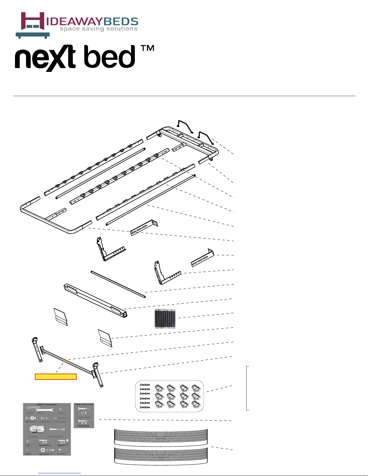
Diagram 1.
MWBS
MWBS
MWBS
MWBS
MWBS
MWBS
Section 1: LAY OUT PARTS
Unpack and familiarize yourself with the components.
Single, Double and King
size Next Beds™ are packed in 3
boxes (Single 2 boxes). Remove the entire contents of
boxes and lay the components out on the floor in the
manner of Diagram 1. Double check the cartons to be sure
you have not missed any parts left in the packing materials.
The Hardware is organized in the card step by step for
convenience.
Do not remove hardware or Slat Holders until directed.
COMPONENT LIST
SINGLE
SINGLE - 38”x75”
DOUBLE - 54”x75”
KING - 60”x80”
A. Mattress Retainer Bar
MWBS
MWBS
MWBS
MWBS
B. Head Frame (1)
C. Center Rail (Double & King Bed)
D. Side Rail (Pair)
(900x1900mm)
-35”x75”
(970x1900mm)
(1370x1900mm)
(1500x2000mm)
- Single Bed (1)
- Double & King Bed (2)
Mattress Size
PUL
L TO OP
EN
PULL TO OPEN
Bed Open Label
Slat Holder Bag
E. Leg
Actuator Bars (2)
F. End Frame (1)
G. Wall Mount Bracket (2)
H. Floor Yokes (Pair)
I. Yoke Connector Bar (1)
J. Bottom Spring Tube (1)
K. Springs (6-Single, 8-Double and 10-Queen)
L. Spring Cover (2)
M.Leg Connector Tube (1)
N. Legs (Pair)
Slat Holder
(3-Single, 6-Double or King)
O.
Opened Slat Holder
(3-Single, 6-Double or King)
Self Tapping Screw
(6-single, 12-Double or King)
P. Hardware Card NB#1 (1)
Hardware Card NB#2 (1, Double or King)
(coordinates with step numbers)
Q.Slats (13-Single, 26-Double, 28-King)
Updated130717MWBS
1.
Page 2
Section 2: YOKE ASSEMBLY
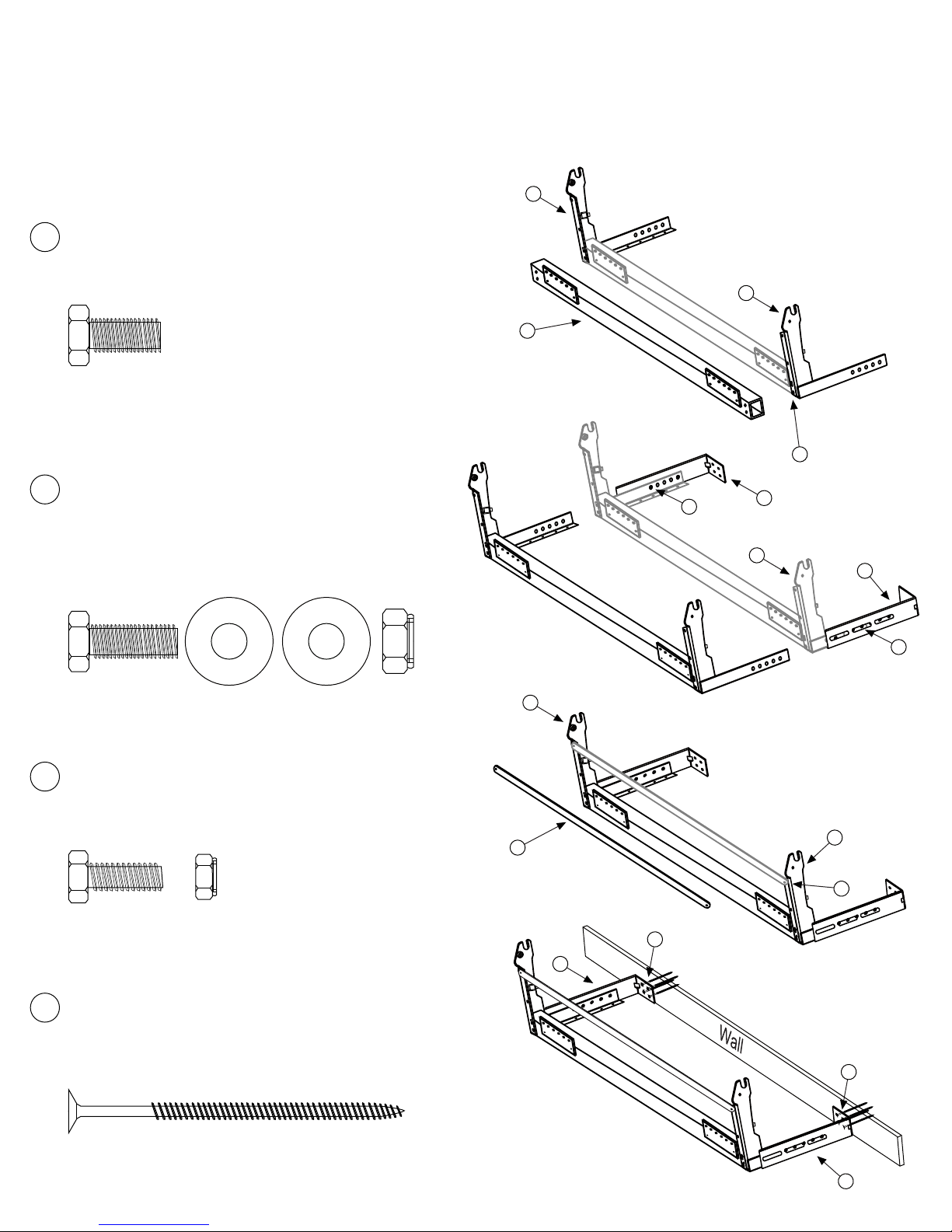
Assemble the Yoke Assembly components as shown. If you are installing the bed in a 16” deep cabinet,
fasten the Floor Yokes and Wall Mount Brackets together not to exceed a 15” projection from the base
board or wall. Secure the Yoke Assembly to the base or wall with the screws provided while following the
steps below. Match fasteners with the actual-size drawings to ensure you use the correct pieces.
H
Attach the Bottom Spring Tube (J) to the Floor Yokes (H).
1.
M8x20mm Bolt (4pcs)
H
J
1
Attach the Wall Mount Brackets (G) to the Floor
2.
Yokes (H) using the Bolts, Nuts and
Washers shown below. Place bolt heads on outside.
Do not tighten bolts now so you can adjust later.
M8x20mm Bolt, 2 Flat Washers, Nylock Nut (4 sets)
2
G
H
G
Attach Yoke Connector Bar (I) to the
3.
Floor Yokes (H).
M6x18mm Bolt, Nylock Nut (2 sets)
4.
Insert screws through Wall Mount Brackets (G) and into
Wall and Base Board at a downward angle.
8-3" (76.2mm) Flat Head Screw (8pcs)
2
H
I
4
G
H
3
4
Updated130717MWBS
2.
G
Page 3
Section 3: BED FRAME ASSEMBLY
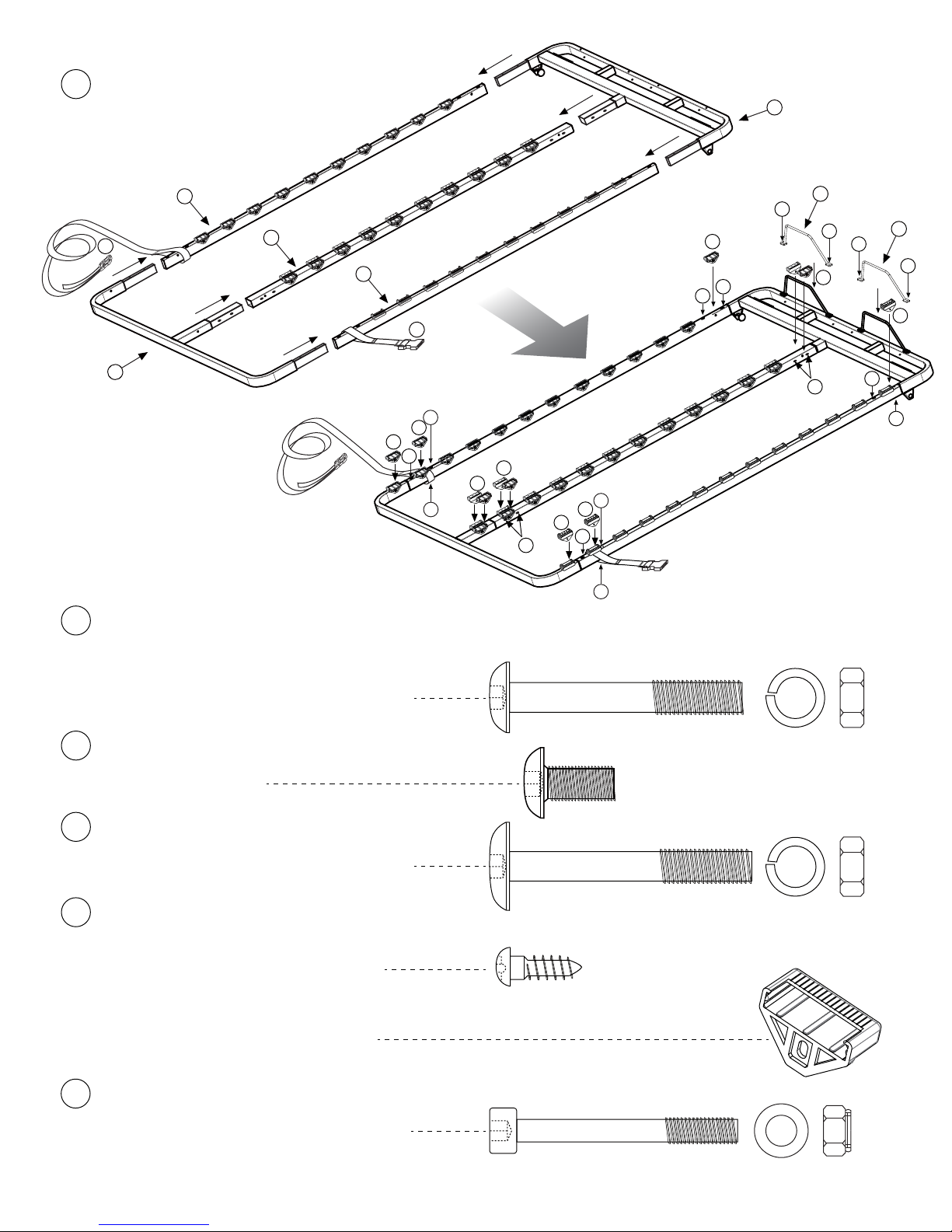
Feed one end of each Side Rail (D)
5.
through the loops of the Nylon
Mattress Strap.
B
D
5
C
D
MWBS
F
Slide End Frame (F), Head Frame (B), Side Rails (D)
6.
and Center Rail (C) together as shown.
Attach End Frame (F) and Head Frame (B)
to Side Rails (D); 2 bolts at foot, 4 bolts at head.
M8x53mm Bolt, Lock Washer, Nut (6 sets)
MWBS
MWBS
MWBS
MWBS
MWBS
MWBS
MWBS
MWBS
MWBS
9
6
6
10
A
10
A
10
MWBS
9
10
MWBS
9
5
8
7
9
9
6
7
9
MWBS
9
MWBS
8
7
9
MWBS
9
MWBS
6
MWBS
MWBS
MWBS
MWBS
MWBS
MWBS
MWBS
MWBS
MWBS
MWBS
6
MWBS
MWBS
MWBS
6
7
Attach End Frame (F) to Side Rails at Leg end.
7.
Bolts do not go through frame.
M8x16mm Bolt (4pcs)
Attach End Frame (F) and Head Frame (B)
8.
to Center Rail (C). (For Double and King Beds only)
M8x55mm Bolt, Lock Washer, Nut (4 sets)
Attach Opened Slat Holder (O) to
9.
End Frame (F) and Center Rail (C).
*One Slat Holder across from one Open Slat Holder*
#5x16mm Self-Tapping Screw (12pcs)
Open Slat Holder attach to Side Rails and Center Rails
(6pcs-Single, 12pc-Double and King)
Attach Mattress Retainer Bar (A) to Head Frame (B)
10.
M6x50mm Bolt, Washer, Nylock Nut
(Single-2 Sets, Double and King-4 sets)
**Do not attach Leg Actuator Bars (E) at this time**
- not shown to scale
Updated130717MWBS
3.
Page 4
Section 4: LEG ASSEMBLY
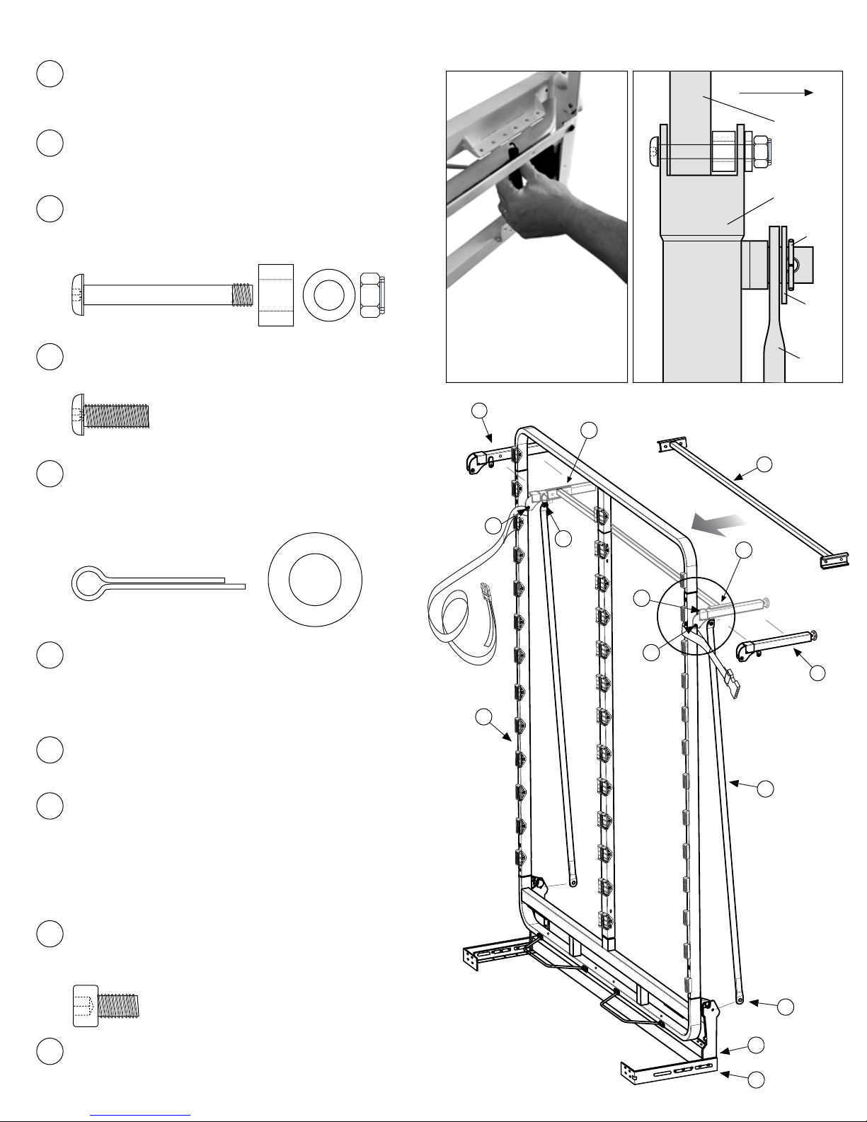
Stand the assembled frame. Lift and set the hinge
11.
axles of the Head Frame (B) into the hinges of the
Yoke Assembly.
Stabilize the frame in the vertical position by
12.
applying one spring on either side (Photo 1).
Detail A - not full scalePhoto 1
inside of frame
(D)
Attach Legs (N) to Side Rails (D), see Detail A.
13.
Do not over tighten so Legs may pivot freely.
M6x42mm Bolt, Spacer, Washer, Nylock Nut (2 sets)
Attach Leg Connector Tube (M) to Legs (N) as shown.
14.
M6x16mm Bolt (4 sets)
Attach Actuator Bars (E) to the Leg Brackets (N)
15.
with Cotter Pins (see Detail A), then to the Floor
Yokes (H) with Cotter Pins. Bend back ends to secure.
Cotter Pins, Washers (4 sets)
Rotate the bed down horizontal and install the
16.
Slats (Q) by slipping one end into the closed Slat
Holder and flexing the slat slightly and tapping it
into the open ended Slat Holder.
Put Mattress in place and secure with Nylon Web Strap.
17.
First hook bottom of spring in
the Bottom Spring Tube (J),
then using vice grips pull up
and set the top spring hook.
You may use leverage from
the Yoke Connector Bar (I).
N
14
13
15
D
15
Detail A
13
(N)
cotter
pin
washer
(E)
M
14
SBWM
SBWM
SBWM
SBWM
SBWM
M
SBW
N
Install proper number of Springs to balance. Raise
18.
bed frame with mattress to the vertical position. Add
an equal number of springs on each side until the
bed frame is almost weightless at the 45* angle.
Remem-ber that the system will weigh slightly more
when bedding is added to the system. See Photo 1.
Install the Spring Covers (L) to the Bottom Spring
19.
Tube (J) to cover the installed springs.
M6x10mm Bolt (4pcs)
Adjust the Wall Mount Brackets on the Yoke Assembly to have the bed
20.
operate at the minimum distance from the wall.
Updated130717MWBS
4.
Tighten bolts in place.
SBWM
M
SBW
M
SBW
BWM
S
SBWM
SBWM
SBWM
E
15
19
H
Page 5
Section 5: Next Bed MEASUREMENTS
To assist in floor space planning and bed cabinet fabrication. inches(centimeters)
Measurements with mattress up to 8” (20cm)
Single Double
King
Next Bed frame width 38” (97) 53”(135) 59”(150)
Next Bed frame height 80”(203) 80”(203) 85”(218)
Projection from wall (P) - Bed closed
Projection from wall (P) - Bed in use
13”(33) 13”(33) 13”(33)
80”(204) 80”(204) 84”(214)
Height - Floor to top of mattress in use 24”(61) 24”(61) 24”(61)
Suggested inside cabinet depth 16”(41) 16”(41) 16”(41)
Suggested inside cabinet width 43.5”(110) 58.5”(149) 64.5”(164)
Suggested inside cabinet height 81.25”(206) 81.25”(206) 86.25”(219)
Mattress size width
36”(90)
54”(137) 60(152)
Mattress size length 75”(190) 75”(190) 80”(203)
Next Bed may be used with or without a cabinet. The cabinet does not attach to the Next Bed mechanism. The cabinet must
be secured to the wall to insure its position relative to the Next Bed frame. Allowances have been made within the interior
cabinet sizes to provide for bed linens to easily be enclosed in the available space.
Listed are the suggested bed cabinet components, the finished cabinet installed sizes, and the measurements for a
16” (41cm) deep cabinet with a 8” (20cm) thick mattress. If you wish to use a mattress thicker than 8” (20cm), you must
increase the depth of the cabinet components - the side panels and the main header, proportionally.
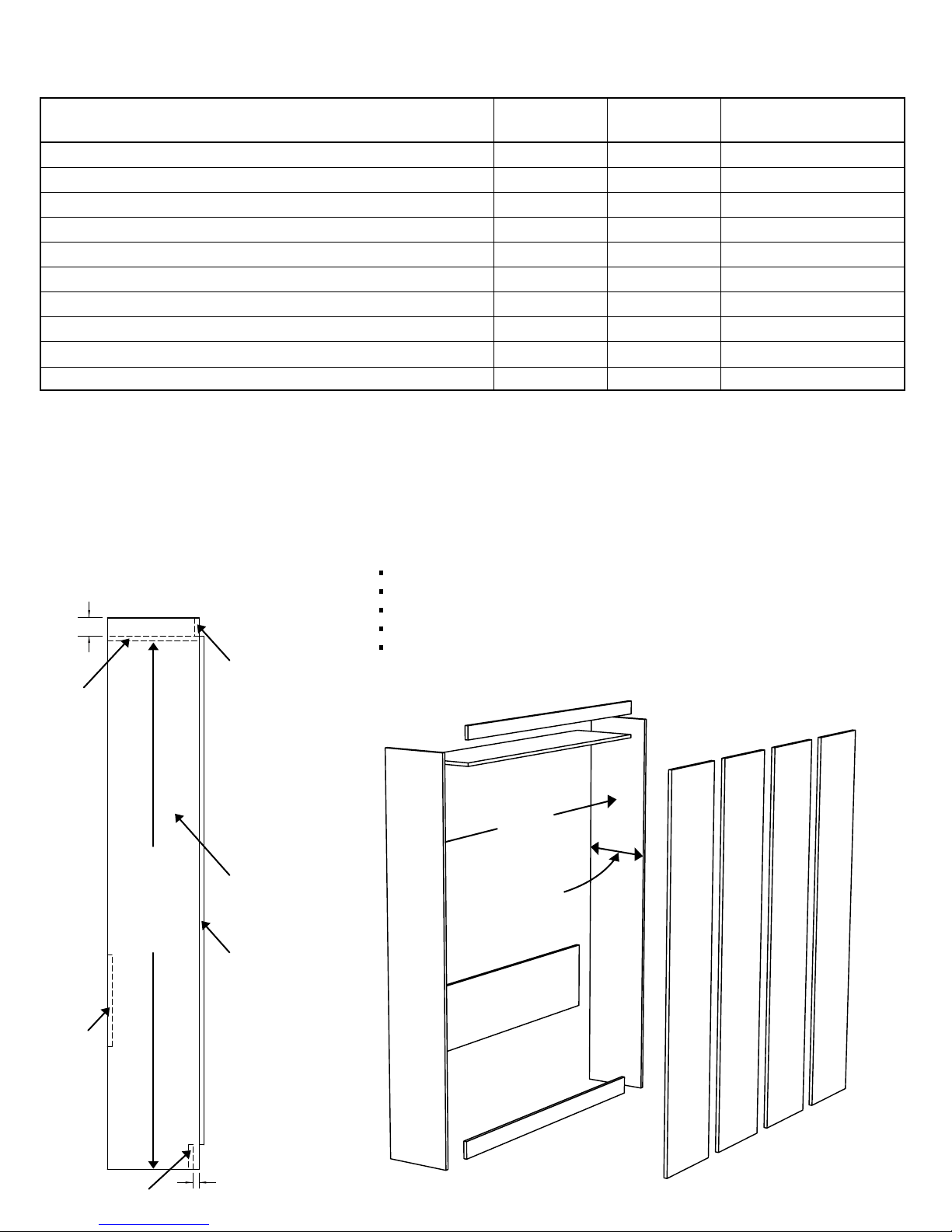
Section 6: CABINET COMPONENTS
3”
C
Top Valance (C) mounts on top of the Main Header (B)
The top of the Main Header (B) is 3” down from the top of the Side Panels (A)
The Doors (E) are mounted 3” down from the top of the Side Panels (A)
Outside Doors(E) mount to Side Panels(A) with hinges from inside
The Bottom Kick(D) is recessed 1” from the front edge of the Side Panels (A)
B
A
Inside Height
F
D
E
Front
1”(25)
C
B
Inside
Width
Inside
Depth
F
A
E
E
A
D
E
E
Updated130717MWBS
5.
Page 6
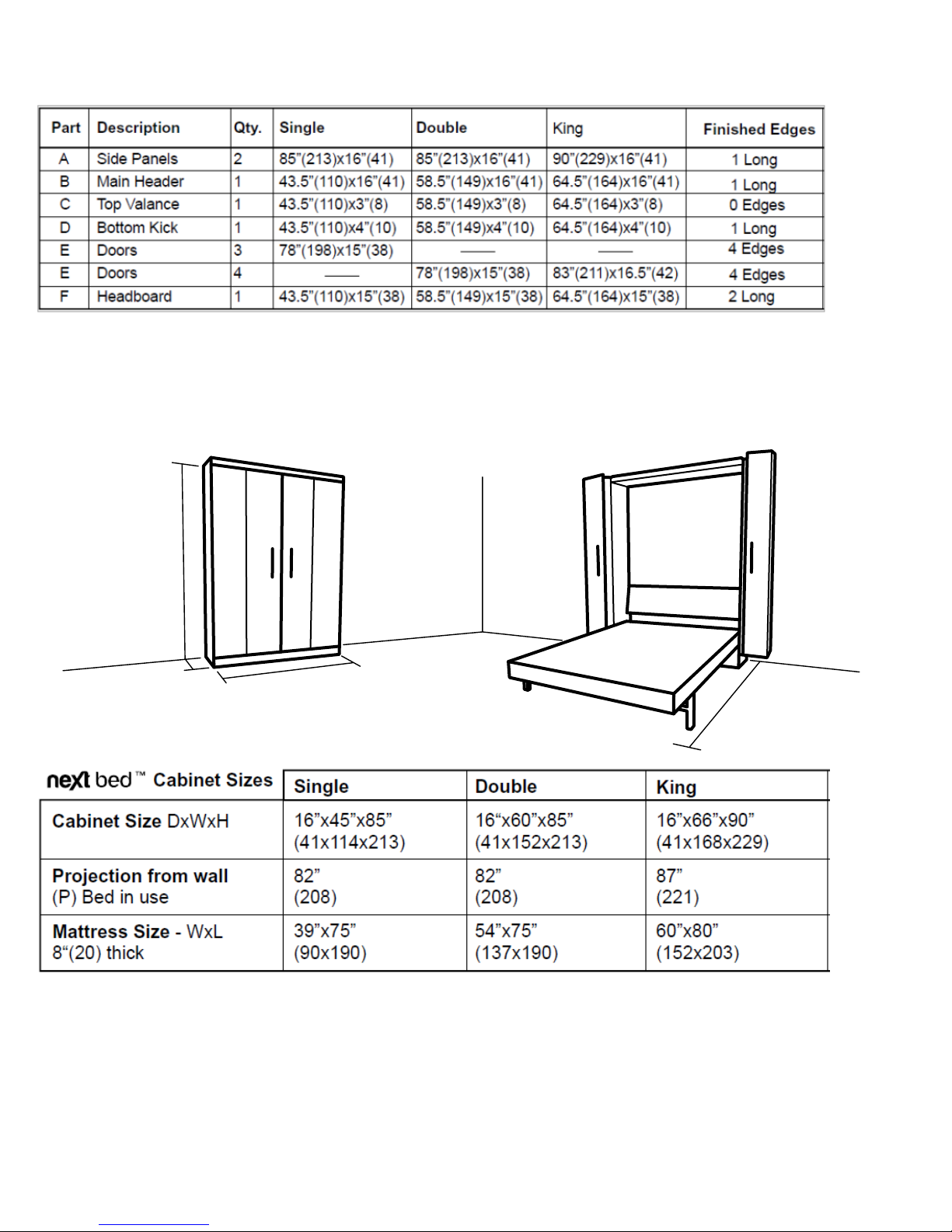
Section 7: CABINET CUT LIST
All dimensions are finished sizes. All material is 3/4 inch thickness. inches(centimeters)
Section 8: FOOTPRINT DIMENSIONS
Cabinet Size & Projection from Wall
All beds accept mattress thickness up to 8" (20cm) (see footnote for thicker mattresses).
inches(centimeters)
D
H
W
CLOSED
USE
P
Notes: A King size Next Bed is two single Next Bed frames bolted together at the foot end with a 0.5”(1.27mm)
plywood spacer between the frames to allow the automatic legs to operate.
If you wish to use a mattress thicker than 12” (30), you must mount the Next Bed frame a greater distance from the
wall by extending the Wall-Mount-Brackets. The cabinet may be made deeper by increasing the width of the Side
Panels (A) and the Main Header (B) only. All other cabinet components remain the same. (Refer to Cabinet Cut List
above)
Updated130717MWBS
6.
 Loading...