

Page 1

Unit 1, Bluewater Estate, Bell Close, Plympton, Devon, PL7 4JH
Hideaway Bed Frame and Cabinet Assembly Guide
CAVOBT(E)150x200cm CABINET CONSTRUCTION & ASSEMBLY GUIDE
Issued 02/07/12, Hideaway Beds Ltd
Revised: 06/07/12, 01/10/12, 14/1/14, 28/1/14, 19/05/16, 13/07/17
By using this guide, you hereby agree to the following:
Our own patent internationally protects all manufactured items. Your statutory rights as a consumer
are not affected. Please note that we practice a policy of continual review and reserve the right to
change the above guide at any time without notice. E&OE Hideaway Beds Ltd July 2017.
Page 2

2 | P a g e
The following notes are intended as a guide for the construction of cabinets to mount and accommodate
the Hideaway (CAVOBT(E)) 150 mechanisms and bed frames. Due to the difference in cabinet making
styles and fitting techniques, it is suggested that a prototype cabinet is made using this guide in order to
tailor these instructions to suit your individual requirements.
IMPORTANT: If packaging is damaged check bed frame for any damages and all components are present.
If any items are missing contact your retailer immediately. Under NO circumstances store/lay objects
under the bed or between the door and bed-frame when in the horizontal position, doing so will result
in damages to the door and bed frame.
Component List
1 X Bed frame (in 2 pieces) 2 X Bedding straps
3 X Bed frame joining bars 2 X Mounting Plates + fixings
5 X Joining bars for doors 2 X Mechanisms
2 X Mattress support bar 1 X Mechanism fixing kit
2 X Leg-Guides 2 X Wall brackets
2 X Adjustable feet 2 X Sub-frame bars
Suggested Cabinet Dimensions
1. For cabinet dimensions see attached drawing
2. The cabinet should be made from 18 mm thick panels
3. The overall cabinet height can be varied by altering the size of the top door. This in turn will
make the footboard higher or lower than the mattress when the bed is down. The bottom door
MUST always be 1615 mm high.
4. Cabinet widths are indicated on the attached drawings and obviously vary with bed size, but the
internal measurement must always be 64 mm wider than the bed frame to accommodate
mechanisms and mountings.
5. The plinth height should be 100mm. Cabinet base should not be added on this size, as the head
end of the bed sits lower than the height of the plinth.
Bed Mechanism & Cabinet Assembly
1. IMPORTANT: Always make sure that the cabinet is securely fastened to the wall (angle brackets
supplied) and adjoining cabinets, if possible. All wall bed and cabinet fixations must be regularly
checked.
2. When building your prototype, if possible, set the cabinet out from the wall to enable access to
understand the workings of the mechanism. Fit mounting plates to cabinet sides before sighting,
as you will need access to the outsides to fit bolts.
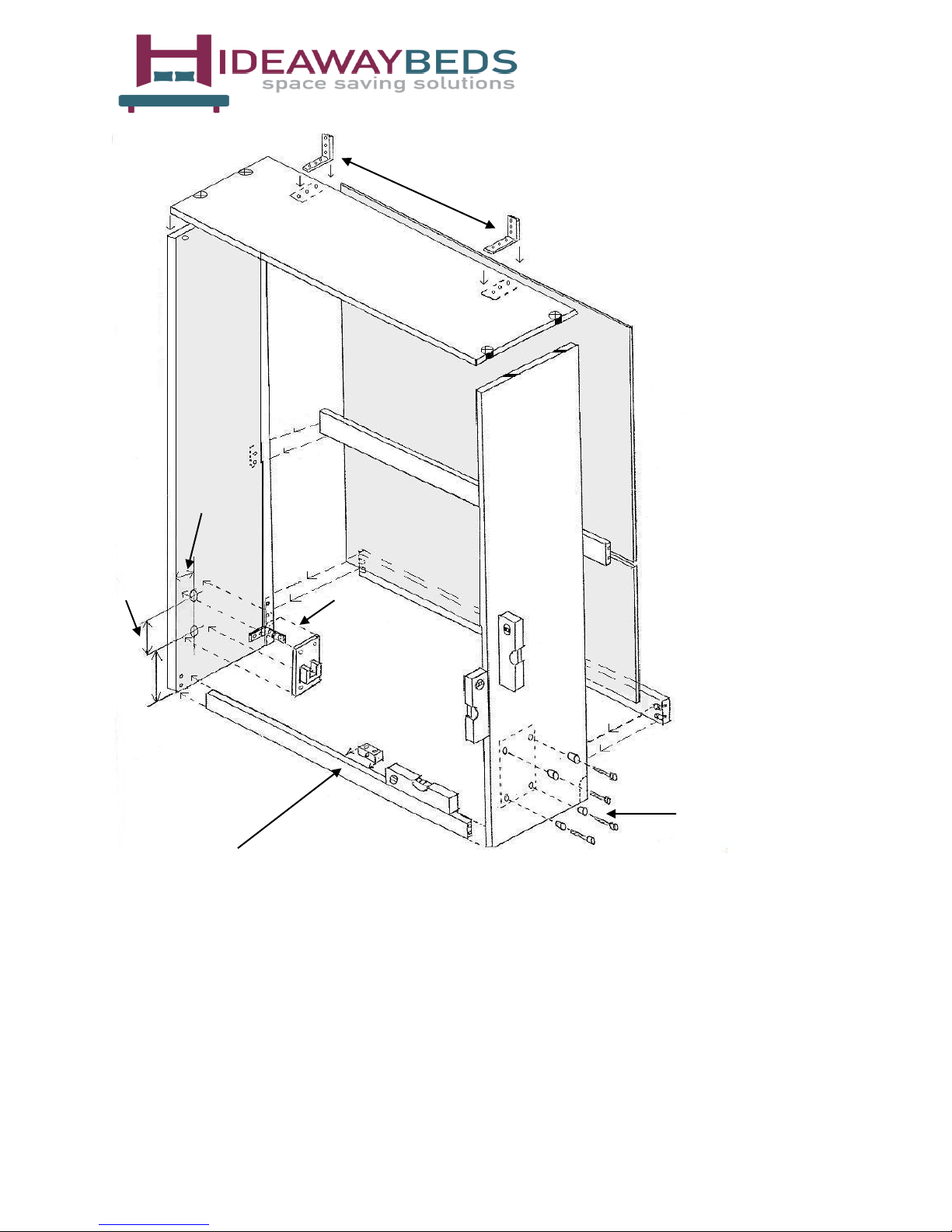
3. The bed can now be mounted in the cabinet. The cast iron mounting plates are supplied with
nuts, bolts and countersinks and MUST be used; the countersinks are to be set into the side
panels for extra bearing strength - when the bed is under tension these are the points of most
stress. The position of these plates in the cabinet is an important dimension and must be
accurately drilled (page 4). Slacken the mechanism adjusters (anti clockwise) and ensure
that the allen bolts on the mechanism are slackened. The sub frame is dismounted and packed
flat. Only attach the automatic legs to the bed frame at this point. Now mount the bed frame
within the cabinet.
All rights reserved. O&OE. © Hideaway Beds 2017.
Page 3

3 | P a g e
4. Now your cabinet is assembled and attached to the wall the headboard can be assembled. This
is a simple arrangement, but important for safety by stopping ‘things’ falling down behind if the
bed is lifted. A board slightly higher than the mattress, chamfered at the top edge is bolted to
the bed frame. The chamfered end can then be attached to another chamfered edge board with
a piano hinge, allowing it to run up and down automatically (see page 7).
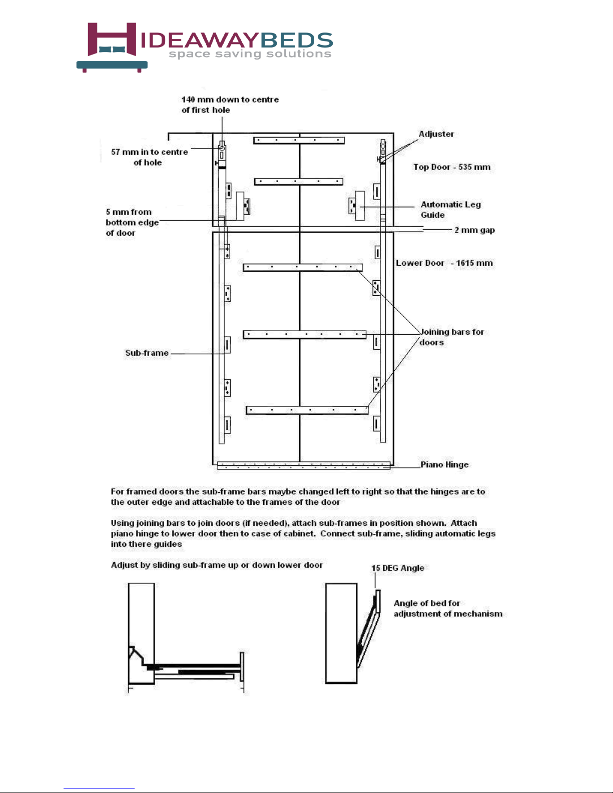
5. Lay the doors face down on the floor. Fix the joining bars supplied to the doors, evenly spaced
and central, attaching piano hinge to the inside face of the lower doors. Allow a 2 mm gap
between all doors.
6. Now attach sub frames in position shown (see page 5). It is very important that the measurement
of 140mm from the top of the door panel to the first hole of the sub frame is accurate, however
if the door size has been either increased or decreased in size from the size advised in this guide
this measurement must be adjusted accordingly. If this measurement in incorrect the geometry
of the bed system will not operate correctly. The doors should be blocked up level with the
plinth, and then the bottom door can be attached to the base (with piano hinge)
7. With the doors attached to the cabinet, the bed frame and sub frame can be joined together
using bolts in the sub frame fixing position.
8. Carefully lift the door and bed frame to its vertical position and check that the doors are correctly
aligned, if not then adjustment can be achieved by sliding the sub frame up or down the doors.
Adjustment of the level of the bed from left to right can be achieved with the allen bolts in the
mechanism lugs and the adjusters on the automatic feet. The adjusters on the footboard, part
of the sub-frame, only sets the footboard vertically when the bed is down.
Adjusting the Bed Mechanism
When the bed is under tension it will hold the doors tight to the cabinet. The mattress must be on the
bed for adjustment (using straps supplied). Checking the cabinet is securely fixed to the wall, adjust
the mechanism with the bed slightly out (see page 4). Tighten hand tight evenly each side then using a
24 mm socket and ratchet (or similar) tighten the mechanisms again eight to twelve turns. The weight
of the mattress and doors will determine the adjustment needed, but the aim is for smooth light action
(note – sometimes springs will creak when settling). Bed, mattress and door should be made to self
balance at 45º angle.
Tilting Doors
If the top doors are tilting once installed, you need to slacken the mechanism off at a 15 degree angle
and then lower the bed into the down position. Once the bed is down you will see there is a black allen
bolt on the mounting plate(s), which needs to be turned anti-clockwise until the doors are level /
straightened. Once this has been done you need to re-tension the mechanism – as above.
All rights reserved. O&OE. © Hideaway Beds 2017.
Page 4
60 mm
(Front edge of cabinet)
4 | P a g e
Angle Brackets
Side Panel -
500 mm
96 mm Mounting Plate
Position
275 mm
Plinth
Please note all dimensions are in MM – not to scale
Overall Height 2260
Minimum cabinet depth 500
Top Door(s) 4 x 535 x 397 mm (3 x 535 x 529)
Bottom door(s) 4 x 1615 x 397 mm (3 x 1615 x 529)
Plinth 100 mm
Internal cabinet width 1564
Use level to square the cabinet(s)
Nuts, Bolts & Countersinks -
MUST BE USED
Single Bed with 2 Panel Door shown for Illustration Only
All rights reserved. O&OE. © Hideaway Beds 2017.
Please note these are guidelines only
Page 5
5 | P a g e
All rights reserved. O&OE. © Hideaway Beds 2017.
Page 6
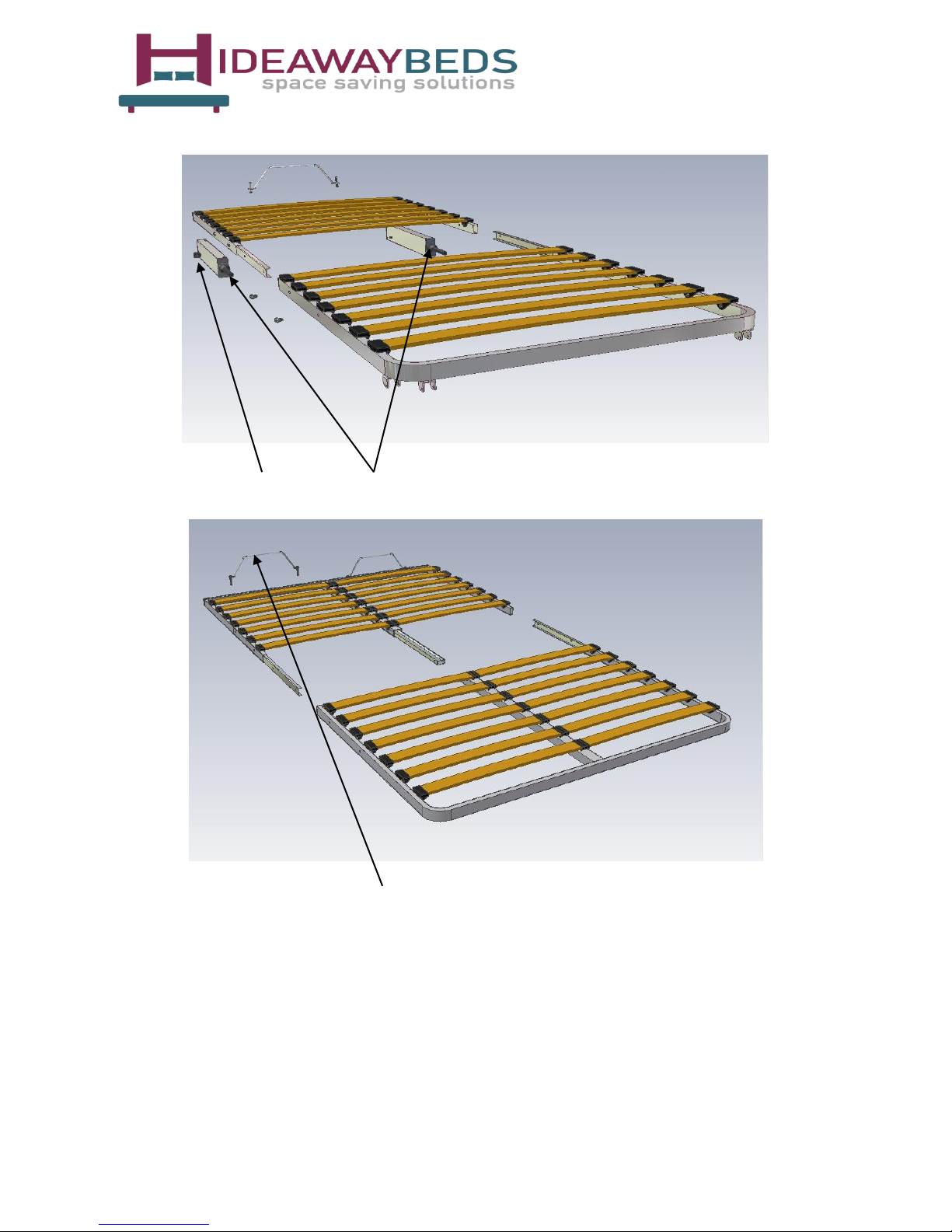
Single Bed shown for Illustration Only
Lug Mechanism
Bed Frame Assembly - King Bed
6 | P a g e
All rights reserved. O&OE. © Hideaway Beds 2017.
Mattress Support Bars
Page 7
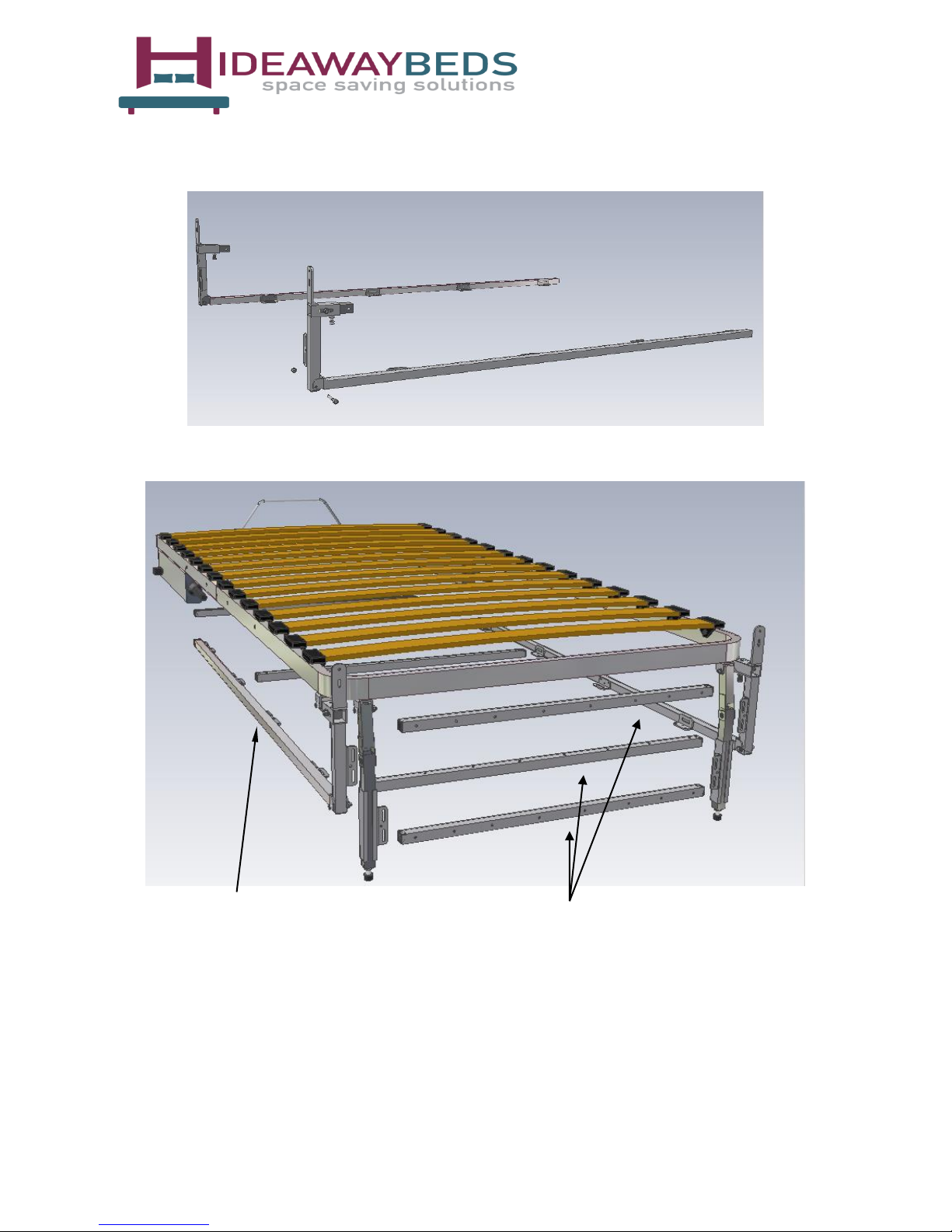
Sub-Frame
7 | P a g e
Single Bed shown for Illustration Only
Sub-Frame Door Joining Bars x 5
All rights reserved. O&OE. © Hideaway Beds 2017.
Page 8
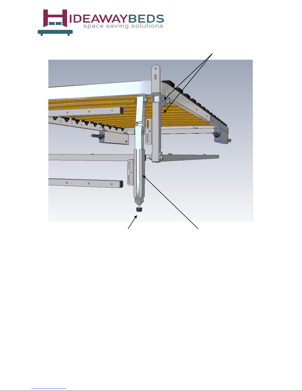
Single Bed shown for Illustration Only
8 | P a g e
Adjusting Bolts
Adjustable Feet Automatic Leg Guides
All rights reserved. O&OE. © Hideaway Beds 2017.
Page 9
9 | P a g e
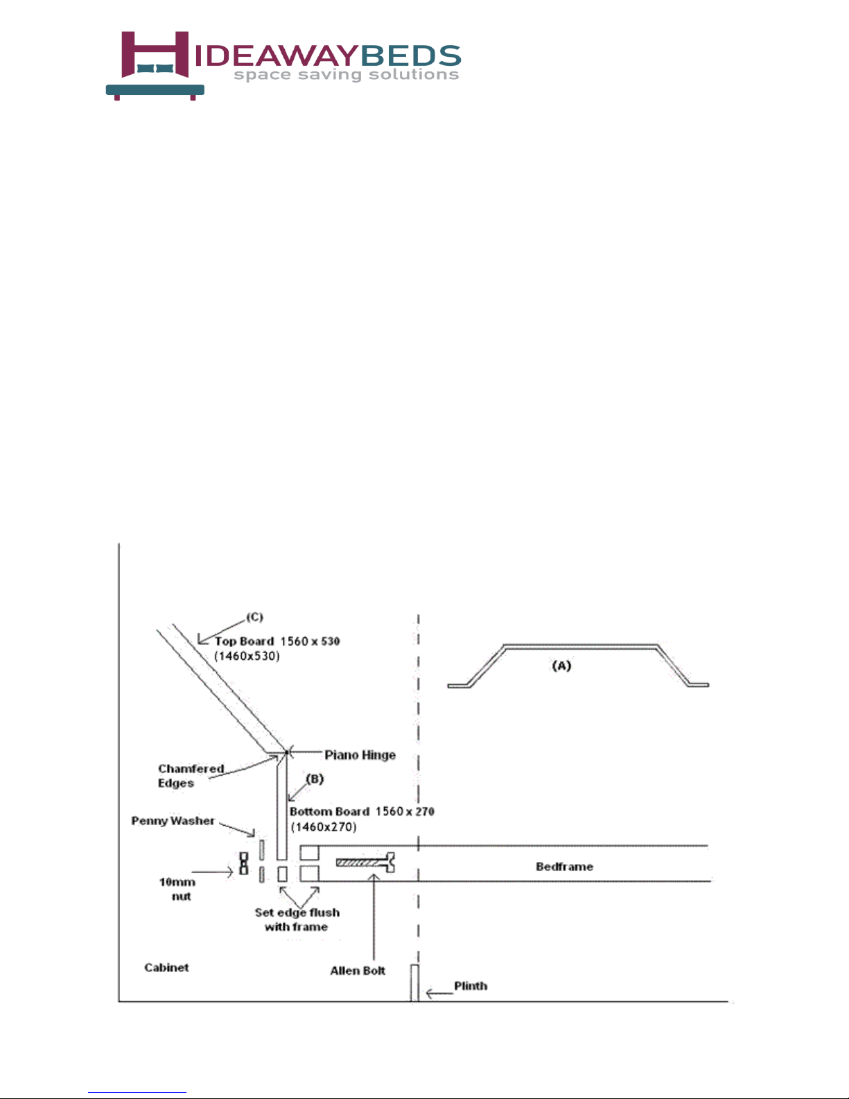
Headboard arrangement for an integrated cabinet
Please note headboard arrangement and fixings are not supplied. The headboard arrangement is
intended as a guide based on our suggested cabinet depth – see page 2. Headboard dimensions are noted
below (double dimensions in brackets).
All bed frames are supplied with mattress support bars (A) but these are to be disregarded where a
headboard will be in use – please retain the Allen bolts and nuts for re-use.
The bed frame will need to be held at the foot end in the horizontal position by another person whilst
attaching the headboard arrangement and the smaller panel (B) of the preassembled headboard is to be
bolted to the bed frame head therefore remove some of the slats at the head of the bed to allow better
access for this.
Suggested method:
Place the headboard into the position shown (the angled cut at the back). Align the headboard (C) with
the cabinet sides with a 1 mm gap each side. Clamp the small panel (B) to the head of the bed-frame
so the bottom edge of the panel is in line with the bottom edge of the bed-frame. Drill through the
metal bed-frame and headboard panel with a 6 mm metal drill. Push the Allen bolts through the holes
and place a penny washer behind the headboard panel and tighten the 10 mm nut onto the back. Replace
the bedding slats and test to sure free movement when folding the bed.
All rights reserved. O&OE. © Hideaway Beds 2017.
Page 10

10 | P a g e
Fitted By:
Tel No:
Date:
Important Safety Information:
The bed should only be operated by an adult.
Due to the risk of entrapment, children should not play with the bed in the sleeping or stored
positions.
Ensure the bed cabinet is securely fixed to the wall (and adjoining units) before pulling the bed
down.
Always manually control the bed by maintaining hand contact with the bed frame whilst in ascent
and descent. Do not let the bed drop freely or slam when opening / closing.
Fasten your bedding to the mattress using the straps, and secure to the bed before closing the
cabinet. Ensure that no bedding is protruding, as it may cause damage to the mechanism. Secure
the pillow under the foot strap.
Do not remove the mattress whilst the bed is in the horizontal position, unless the bed frame is
being held by another person.
Bed and cabinet should be checked regularly for signs of wear.
lf you are relocating the bed, do not remove any of the fixings until the bed is in a vertical
position. Bed relocation is best done by a qualified fitter.
Adjustable mechanisms should not be tampered with unless by a qualified fitter.
We employ a policy of continuous development and therefore reserve the right to alter specifications
or illustrations in this manual at any time.
All rights reserved. O&OE. © Hideaway Beds 2017.
 Loading...