

Page 1
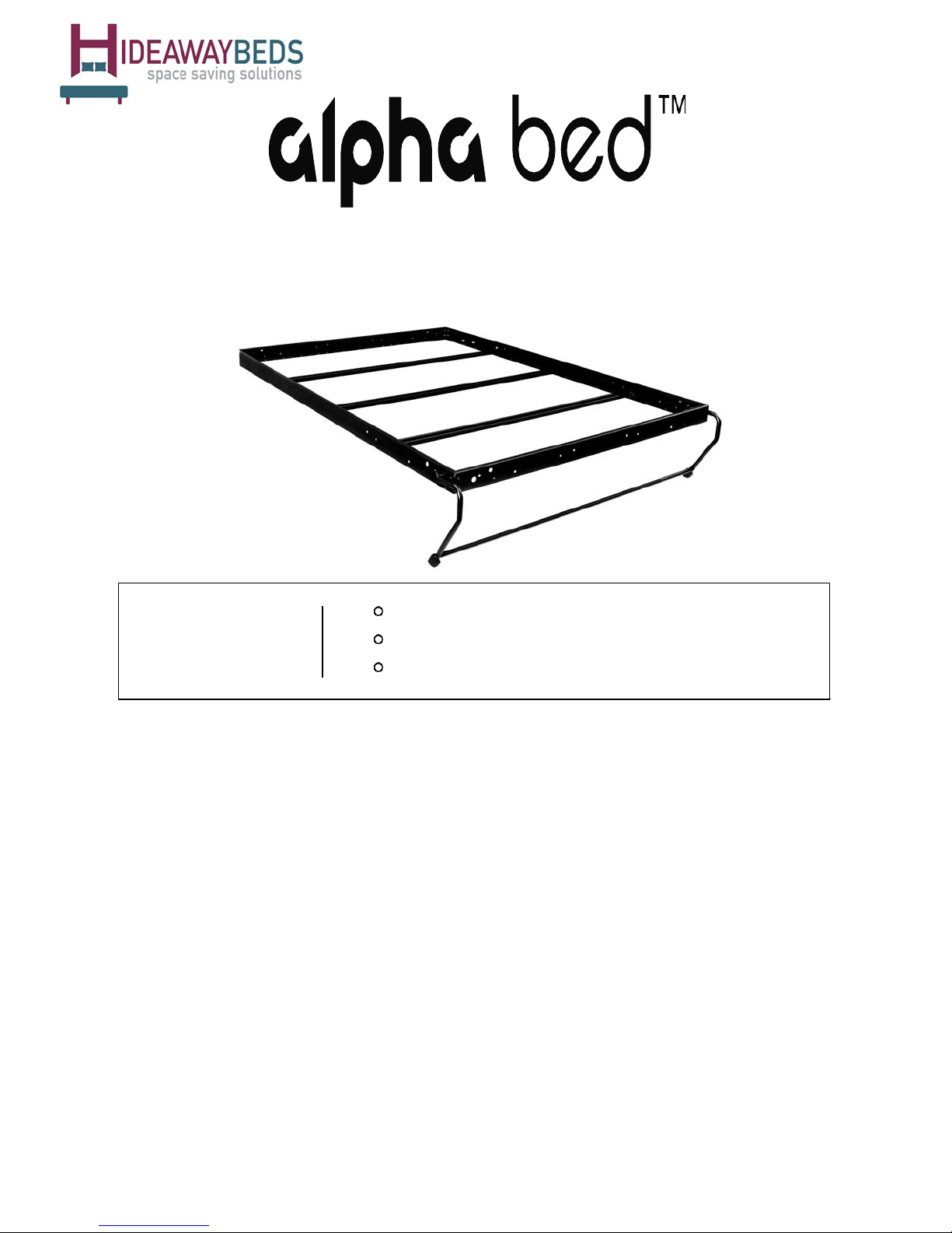
[Model #SBF: Steel Bed Frame]
Stock ed in:
Single
Double
King
Assembly Instructions
One universal bed frame for each of Single, Double, or King wall beds.
May be mounted in either vertical or horizontal modes.
A lightweight, universal, structural steel bed frame with double overlap
steel stiffen ers, compl e te d with fold-away leg system. Designed to
exceed the strength of wood or aluminum as well as residential and
Designed to Exceed International ISO 9002
Standards for residential specifications
www.hideaway.co.uk tel: (01752) 511111
commercial sp ecifications.
Modified: 15/02/13, S. Baker
Modified: 28/03/13, S. Ba ker
Modified: 22/04/13, S Baker
Modified: 13/07/17, M Downton
042213 Update
Page 2

2.
Project Start-Up
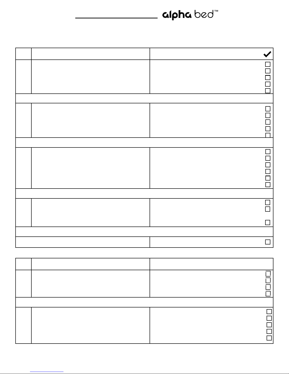
Familiarize yourself with all of the components in the Steel Bed Frame and
mechanism cartons, as well as thoroughly study this manual so you may plan the
steps required to complete this project.
Study all illustrations and plan drawings. Make sure that the space available is
adequate for the specified dimensions of the bed cabinet, both in the open and
closed positions (see cut list pages to cross check dimensions).
Cabinet Panels may be constructed of Ply Core or Particle Board.
Handles to pull the bed open are not provided. Select these from your local
decorative hardware supplier. Have them on site at the time of assembly.
Check to be sure that all items are available
Steel Bed Frame and Mechanism
Cabinet Components and Hardware
Necessary Tools
If you choose a horizontal bed orientation, a separate cut list is provided on page 7
and assembly diagrams are on page 18.
Steps to Complete Project
1.
2.
3.
4.
5.
6.
7.
8.
Prepare all wood or laminate cabinet components.
Mount Lift Mechanism.
Install springs in Lift Mechanisms.
Assemble the Bed Cabinet.
Attach Bed Cabinet to wall and floor.
Assemble Steel Bed Frame to Bed Face Panels.
Install the Bed Face Panel in Cabinet.
Install Handles, Leg Assembly, Mechanism Covers, Mattress
Page 3
3.
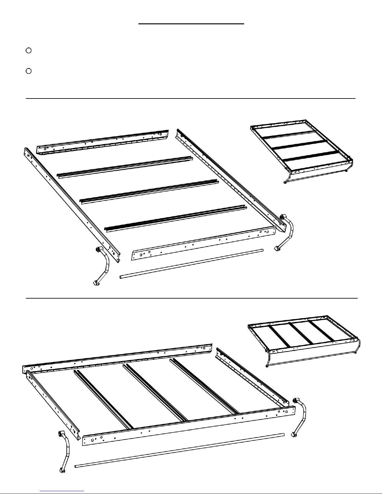
Carton Contents for
2 Frame End Sections
Identical Head & Foot
2 Frame Side Sections
Identical, Right or Left
3 Stiffeners - Bed Face
Space evenly between Frame Sides
2 Fold-away Legs
One Left - One Right
1 Leg Connector Rod
Stabilizes and Eases Leg Operation
Hardware Card #3
14
Bolt 10-24x1/2” (M6x12mm) Black
Bolt Frame corners
2 Bolt 10-24x1 1/4” (M6 x 32mm) Black
Bolt Leg Stop Foot corners
16
Nut 10-24 (M6) Black Nylock
Use with #1214 & #1213
4 Angle 1”x1”x1 3/4” (25x25x44mm) Black
Use inside Frame corners
2 1/2”x3/4” (13x19mm) Round Black Cylinder
Use with #1213 as Leg Stop
Hardware Card #4
2 1 1/2”x5/16” (T1.5x40mm) Black Washer
Secure Leg inside Frame
2 1 1/2”x.765” (T2.5x40mm) Black Washer
Secure Leg inside Frame
2 1 1/2”x.765” (T2.5x40mm) Black Nylon Washer
Between Leg & outside of Frame
2 Nut 5/16” (M8) Black Nylock
Secure Leg inside Frame
2 Bolt 1/4”-20 Black Hex Head
Attach Leg to Leg Rod
2 Star Washer for #1210
Attach Leg to Leg Rod
Hardware Card #5
1 Nylon Web Strap with Buckle
Secure Nylon Web Strap
2 3/4”x1/4” (T1.5x25mm) Washer
Hardware Card #7
1 Lift Mechanism - Right Side
Attach to Right Side Panel
1 Lift Mechanism - Left Side
Attach to Left Side Panel
2 #1 Bags containing 9 Springs each
Install correct number in each Mechanism
1 13” Plastic Pipe
Used to set the Lift Mechanisms
Hardware Card #2
10
Machine Screw 5/16-18 x 1 1/4”
4 Hex Head Bolt 5/16-18 x 1”
2 Allen Head Bolt 5/16-18 x 1”
16
Hex Head Nylock Nut
1 Allen Wrench 5/16“
Note: Each Frame Carton contains one Single, Double or King Steel Bed Frame complete
with leg assembly and necessary hardware. Mechanism components are in separate carton.
Qty. Frame Carton Items
Comments
Secure Mattress to Bed Frame
Secure Nylon Web Strap to Bed
Face Panel under Mattress
2
#8x5/8” (M4x15mm) Wood Screw
110 #8x5/8” (M4x15mm) Wood Screw Attach Steel Bed Frame to Bed Face
Qty. Mechanism Carton Ite ms Comments
To attach Lift Mechanisms to Side Panels
Attach Mechanism to Frame Side section
Position Mechanism Arm on Frame Side section
Secure Bolts and Screws
For Allen Head bolts
Page 4
4.
Component Layout
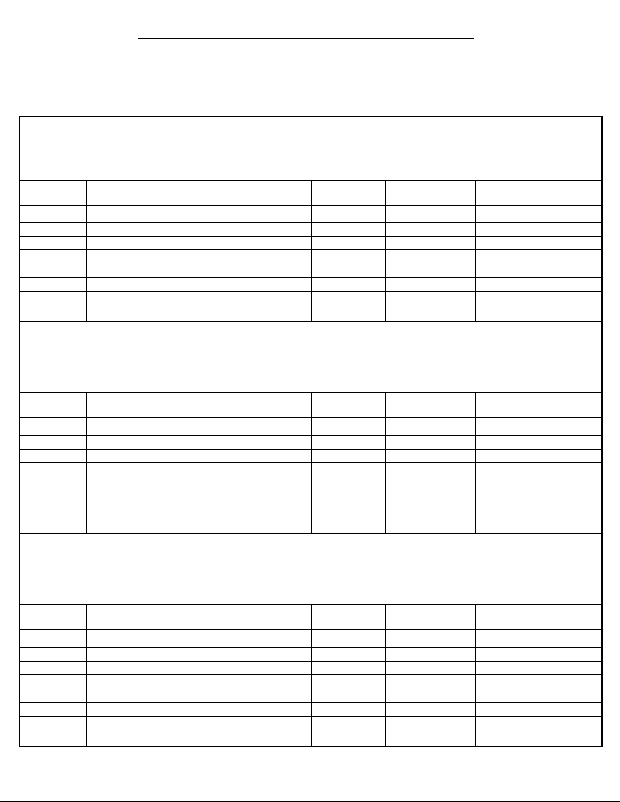
The frame is adaptable as vertical or horizontal (side tilt) bed.
Frame has mounting holes to use any of 4 Power Packs:
SBLM, SBLM-A, ACBM, GPLS
Frame laid out for assembly in the Vertical orientation.
ame laid out for assembl y in the Horizont a l orientation.
Fr
Page 5
5.
Cabinet Cut List (Vertical Orientation)
2 Bed Face Panel
21 1/4” (540)
77 5/16” (1964)
4 Edges
2 Side Panel
16” (406)
83 1/4” (2115)
2 Long Edges
2 Headboard (1) & Top Panel (1)
14 1/4” (362)
43” (1092)
2 Long Edges
1 Top Facia with 13“ (330mm) Leg
2” (51)
43” (1092)
2 Long Edges
1 Bottom Rear Base
6” (152)
43” (1092)
2 Long Edges
1 Bottom Kick with 13” (330mm) Leg
4” (102)
43” (1092)
2 Long Edges
4 Bed Face Panel
14 3/8” (365)
77 5/16” (1964)
4 Edges
2 Side Panel
16” (406)
83 1/4” (2115)
2 Long Edges
2 Headboard (1) & Top Panel (1)
14 1/4” (362)
58” (1473)
2 Long Edges
1 Top Facia with 13“ (330mm) Leg
2” (51)
58” (1473)
2 Long Edges
1 Bottom Rear Base
6” (152)
58” (1473)
2 Long Edges
1 Bottom Kick with 13” (330mm) Leg
4” (102)
58” (1473)
2 Long Edges
4 Bed Face Panel
15 7/8” (403)
82 5/16” (2090)
4 Edges
2 Side Panel
16” (406)
88 1/4” (2242)
2 Long Edges
2 Headboard (1) & Top Panel (1)
14 1/4” (362)
64” (1626)
2 Long Edges
1 Top Facia with 13“ (330mm) Leg
2” (51)
64” (1626)
2 Long Edges
1 Bottom Rear Base
6” (152)
64” (1626)
2 Long Edges
1 Bottom Kick with 13” (330mm) Leg
4” (102)
64” (1626)
2 Long Edges
For Use with Lift Mechanisms: SBLM
Numbers in parenthesis ( ) are millimeters.
For use with 13” (330) Leg Assemblies
Cabinets using 13” (330) Legs use a 2” (51) Facia and 4” (102) Kick. See page 12 for details.
Single
Mattress size: 39”x75” (990x1905)
12” (305) max thickness
Overall Cabinet Dimensions:
44 1/2”w x 83 1/4“h x 16”d (1130w x 2115h x 406d)
Protrusion from wall: 85” (2146)
Cabinet Material: 3/4“ (19) MDF or Plycore
Quantity Description Width Length Finish (Tape) Edges
Double
Mattress size: 54”x75” (1372x1905)
12” (305) max thickness
Overall Cabinet Dimensions:
59 1/2”w x 83 1/4“h x 16”d (1511w x 2115h x 406d)
Protrusion from wall: 85” (2146)
Cabinet Material: 3/4“ (19) MDF or Plycore
Quantity Description Width Length Finish (Tape) Edges
King
Mattress size: 60”x80” (1524x2032)
12” (305) max thickness
Overall Cabinet Dimensions:
65 1/2”w x 88 1/4“h x 16”d (1664w x 2242h x 406d)
Protrusion from wall: 90” (2273)
Cabinet Material: 3/4“ (19) MDF or Plycore
Quantity Description Width Length Finish (Tape) Edges
Page 6
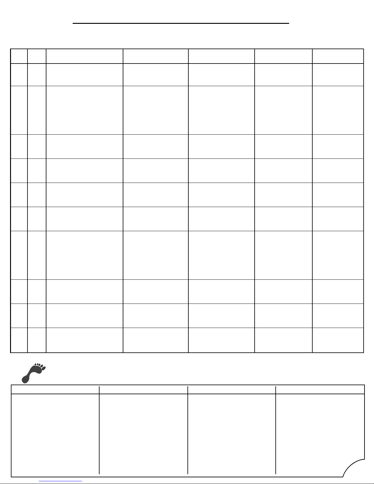
Cabinet Footprint Dimensions & Protrusion Distance from Wall (Horizontal)
Numbers in parenthesis ( ) are millimeters.
Max Mattress Thickness
12” (305)
12” (305)
6
Cabinet Cut List (Horizontal Orientation)
1 2 Bed Face Panel
39” x 41 3/4”
39” x 56 3/4”
41 1/2” x 62 3/4”
4 Edges
Rear Stiffener (1),
Single
Max Mattress Size
54” x 75” (1372 x 1905)
60” x 80” (1524 x 2032)
Cabinet Components Description & Cut List. See pg. 18 for assembl y.
Cabinet Material: 3/4“ (19) MDF or Plycore Numbers in parenthesis ( ) are millimeters.
#
Qty Description Single Double King Edge Band
(990 x 1060)
2
2
Side Panel
for 13“ (330) Leg
3
1
Top Panel 16” x 78 1/2”
4
1
Top Facia 2” x 78 1/2”
5
1
Top Facia Stiffener 3” x 78 1/2”
6
2
Top
Bottom Rear Base (1)
16” x 49 3/4”
(406 x 1264)
(406 x 1994)
(51 x 1994)
(76 x 1994)
4” x 78 1/2”
(102 x 1994)
(990 x 1441)
16” x 64 3/4”
(406 x 1645)
16” x 78 1/2”
(406 x 1994)
2” x 78 1/2”
(51 x 1994)
3” x 78 1/2”
(76 x 1994)
4” x 78 1/2”
(102 x 1994)
(1054 x 1594)
16” x 70 3/4”
(406 x 1797)
16” x 83 1/2”
(406 x 2121)
2” x 83 1/2”
(51 x 2121)
3” x 83 1/2“
(76 x 2121)
4” x 83 1/2”
(102 x 2121)
2 Long Edges
2 Long Edges
2 Long Edges
2 Long Edges
2 Long Edges
7
2
Kick & Kick Stiffener
for 13” (330) Leg
8
1
Head Board 15” x 78 1/2”
9
1
Head Board Stiffener 6” x 78 1/2”
10
Cabinet Size (D,W,H) 16” x 80” x 64 3/4”
Projection from Wall 64” (1626) 70” (1778)
1
Panel Connector 3” x 37”
16” x 80” x 49 3/4”
(406 x 2032 x 1264)
49” (1245)
4” x 78 1/2”
(102 x 1994)
(381 x 1994)
(152 x 1994)
(76 x 940)
4” x 78 1/2”
(102 x 1994)
15” x 78 1/2”
(381 x 1994)
6” x 78 1/2”
(152 x 1994)
3” x 52”
(76 x 1321)
Double
(406 x 2032 x 1645)
4” x 83 1/2”
(102 x 2121)
15” x 83 1/2”
(381 x 2121)
6” x 83 1/2”
(152 x 2121)
3” x 58”
(76 x 1473)
King
16” x 85” x 70 3/4”
(406 x 2159 x 1747)
2 Long Edges
2 Long Edges
0 Edges
0 Edges
39” x 75” (990 x 1905)
12” (305)
Page 7
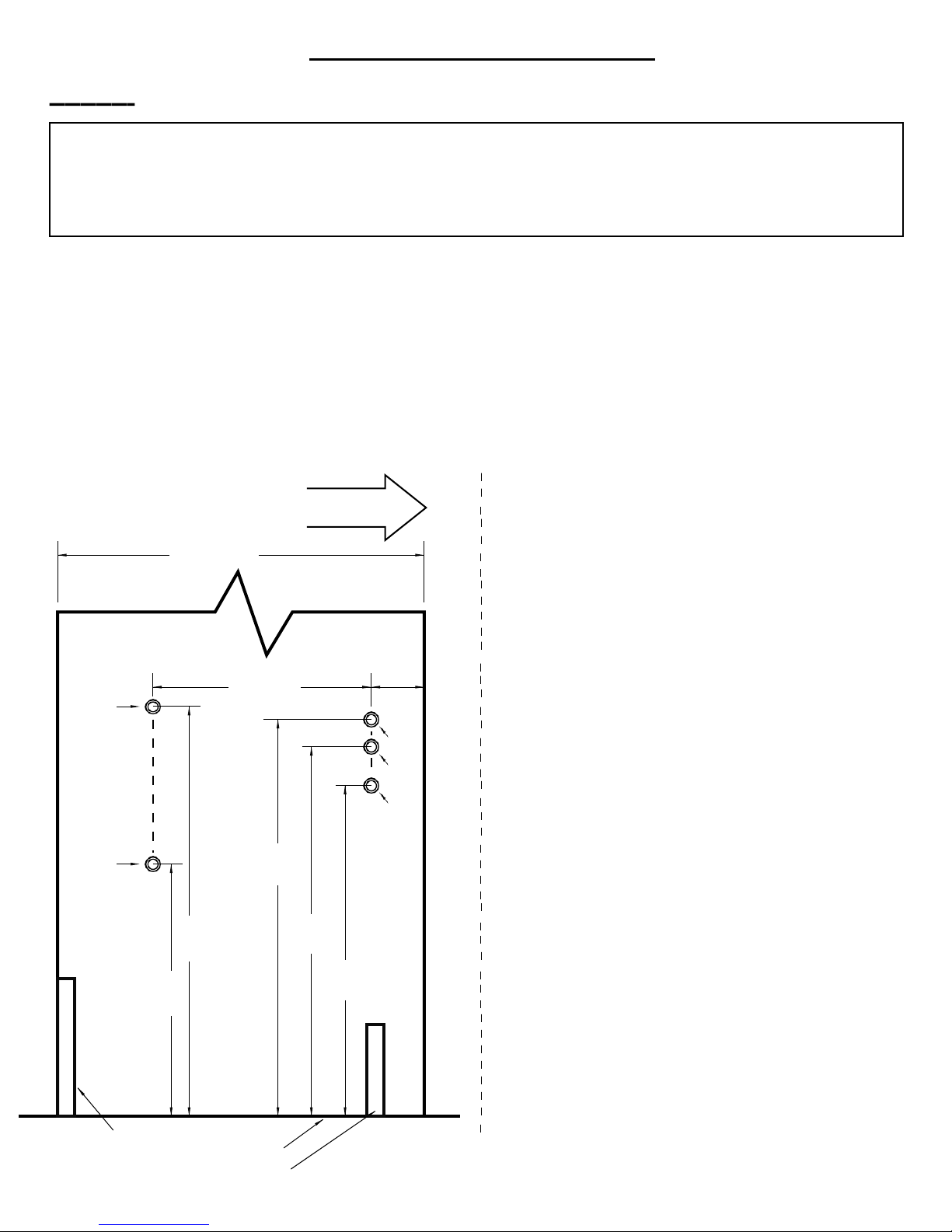
Step by Step Instructions
STEP 1: Mount the Lift Mechanism to the Side Panels
Drill Patterns in Drawing is only for the SBLM Lift Mechanism
Numbers in parenthesis ( ) are millimeters.
1.
Exactly mark the mounting holes on the inside of each side panel.
2.
Drill a 1/16” (2mm) pilot hole for each mounting bolt. Drill the final hole with a 5/16” (8mm) bit.
3.
Counter sink 5/8” (15mm) on the outside of the panels just deep enough for the 5/16” x 1 1/4”
(8x32mm) Machine Screws.
4.
Mount the Lift Mechanisms.
NOTE: All location measurements are from the front edge of the Cabinet Side Panels.
Refer to Drawings 3 & 4.
Drawing 3.
13” (330) Leg
Hole C
Hole D
11.0”
(279)
16.0” (406)
11 13/16”
17 9/16”
17 7/8”
(454)
(300)
(446)
FINISHED FRONT
EDGE OF PANEL
16 1/8”
(410)
14 7/16”
(367)
2 5/16”
(59)
Hole A
Hole B
Hole E
Bottom Rear Base
Bottom Edge of Panel
Bottom Kick
7
Page 8
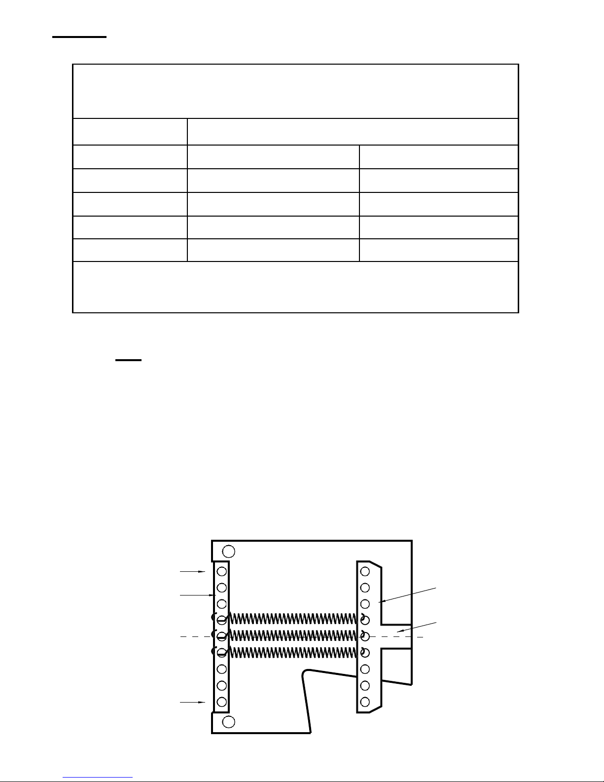
STEP 2: Install the springs on the Lift Mechanisms
Plywood Core
Particle Board
SPRING APPLICATION CHART
Please Note: These are recommendations only. Actual number of springs required will depend
on the total weight of the bed-face unit including the mattress and all bedding.
BED SIZE BED PANEL MATERIAL
Single 2-3 springs per side 3-4 springs per side
Double 4-6 springs per side 5-6 springs per side
King 5-6 springs per side 6-7 springs per side
After you have completed installing and checking the operation of your bed, you
may find it necessary to add or remove springs to achieve the correct lift effort of
between 5 to 10 pounds.
There are nine locations for springs. If the bed requires an even number of
springs, do not use the center hole (#5 from the top). If the bed requires and odd
number of springs, start with the center hole (#5 from the top) and work outward in
both directions evenly.
Hook the springs so the open ends are facing outward. You may have to gently
pry up the tension arm and slide the spring under and snap them into place in the
proper hole, matching the same numbered hole from the top of the mechanism
back plate. You should have an equal number of springs on each side of the
center hole.
Use the same number of springs and the same layout on both the left and right
mechanisms.
Spring Hole #1
Upturned Edge
of Mounting Plate
Center line
Tension Arm
Arm Bracket
Spring Hole #9
Drawing 5.
8
Page 9
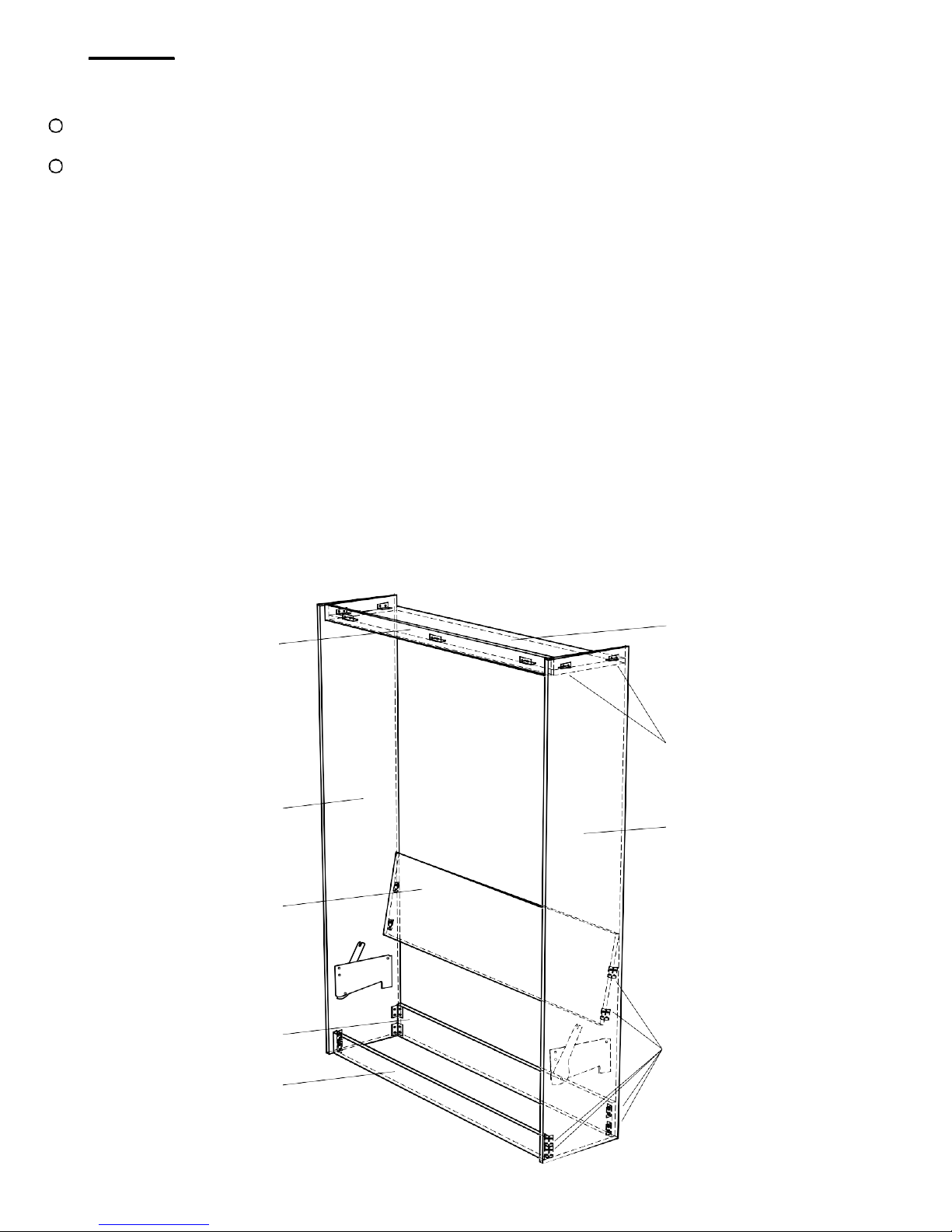
STEP 3: Assemble the Bed Cabinet (Vertical Orientation)
Drawing 6.
If possible, the Bed Cabinet should be assembled in the room where it will be used.
Be sure Lift Mechanisms are securely installed.
1.
Locate the mounting position of the headboard marking the left and right side panels
20” (508mm) from the floor and 3” (76mm) in from the back edge of the panels. Note
from Drawings 6 & 7 that this mounts the bottom edge of the headboard out 3”
(76mm) from the back or wall edge of the Side Panels. Use the 1”x1”x1 3/4”
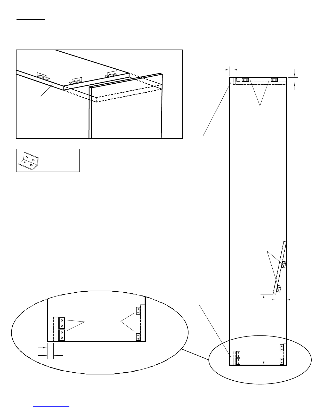
(25x25x44mm) mounting brackets (2 each side). Be sure the top bracket is set low
enough not to protrude beyond the back of the cabinet. Use #8x3/4” (M4x19mm) Pan
head Screws. The Headboard location may vary slightly; just be sure it is secure and
at the approximate 3“ (76mm) distance from the back edge.
2.
Use Angle Brackets to assemble Bottom Rear Base and Bottom Kick in position
shown in Drawings 6 & 7. Use two Angle Brackets on each end.
3.
Attach Top Panel as shown in Drawings 6 & 7. Be sure back edge of the Top Panel is
flush with back of Side Panels and 1 1/4” (32mm) down from the top of the Side
Panels so it is flush with the bottom edge of the Top Facia. The Top Facia will cove
he front edge of the Top Panel.
t
r
Top Facia
Left Side Panel
Head Board
Bottom Rear Base
Bottom Kick
Top Panel
1”x1”x1 3/4” (25x25x44mm)
Angle Brackets
Right Side
Panel
1”x1”x1 3/4” (25x25x44mm)
Angle Brackets
9.
Page 10
10
STEP 3: Assemble the Bed Cabinet (Vertical Orientation) continued
Numbers in parenthesis ( ) are millimeters.
Top Panel
1.0”
(25)
Front
Edge
1”x1”x1 3/4”
(25x25x44)
Right Side
Panel
Angle Brackets
1.25”
(32)
Angle Assembly Bracket
Drawing 8.
Facia
1”x1”x1 3/4”
(25x25x44)
Angle Brackets
Note: Upper
Brackets clear
Wall
1”x1”x1 3/4”
(25x25x44)
Angle Brackets
1.0”
(25)
Kick
20.0”
(508)
Drawing 7.
3.0”
(76)
Page 11
11
STEP 4: Attach Bed Cabinet Securely to Wall
Top Facia
2”x2”
(51x51mm)
Brackets
Warning
Label
Wall
Studs
Rubber
Bumpers (3)
Left
Side Panel
Right
Side Panel
Hints: If the room is carpeted you may raise the kick up to 1/4” (7mm) to clear the
carpet. More than 1/4” (7mm) will obstruct the operation of the bed.
You may or may not wish to remove the Base Board to allow the Bed Cabinet to fit
flush against the wall. If you do remove the Base Board, save for later trim and
replacement. If you do not wish to remove the Base Board, you may use a shim or filler
strip of the sa me thickness at the top between the cabinet and the wall.
1.
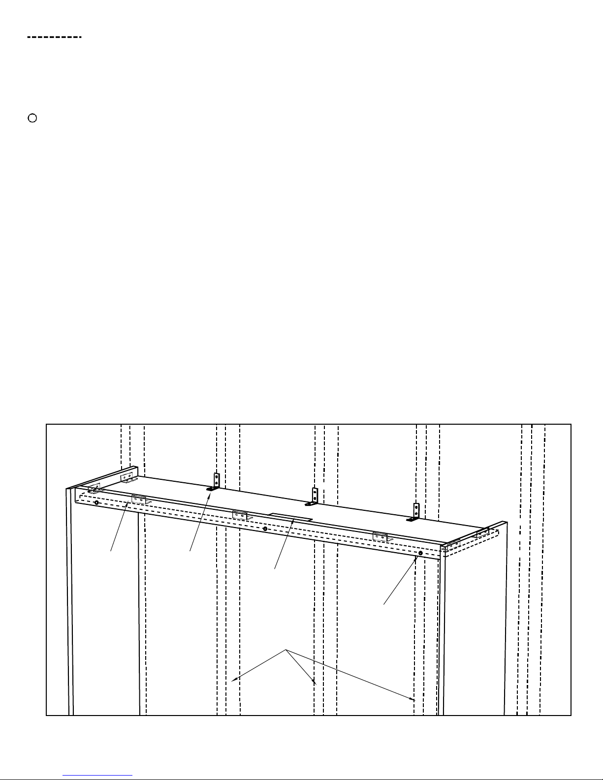
Place cabinet against wall. Make sure the cabinet is level and square. Measure
diagonally to be sure of square. Bed will not operate if cabinet is not square. Check
also for square from front to back as well as side to side. Use shims where necessary.
2.
Prior to placing cabinet against the wall, locate 3 studs or other wall frame members at
the level of the Top Panel (top of bed).
Alert: The cabinet must be secured to studs or other wall structural members using
2” x 2” (51x51mm) L-Brackets. If the wall is not a wood stud wall, use metal stud
screws, toggle bolts or concrete expansion bolts if necessary.
3.
Now that the cabinet is square and plumb, use two #8x2” (M4x51mm) flat head wood
screws in each of three 2”x2” (51x51mm) brackets to attach to studs at the top level of
the Top Panel (see Drawing 9.). Re-check square and plumb and then secure 2”x2”
(51x51mm) L-Brackets to Top Panel with #8 x 3/4” (M4x19mm) wood screws. Attach
warning label to top of cabinet. Attach three Bumper Buttons to bottom of the front
edge of the Top Facia. These Bumpers allow the Bed Face Panel to close quietly.
Angle
Drawing 9.
Page 12
12
STEP 5: Assemble Steel Bed Frame to Face Panels
Stiffener
Attach Nylon Web Strap Here
Stiffener
Stiffener
Frame flush with
end of Face Panels
Drawing 10.
Plan View
Bed Face Panels
Head of Bed
1.0”
(25)
0”
1.
(25)
Bed Face Panel
Drawing 12.
Foot of Bed
Leg Stop
Side View (do not install legs
at this time, it is shown for
reference only)
Floor
Page 13
STEP 5: Assemble Steel Bed Frame to Face Panels, continued
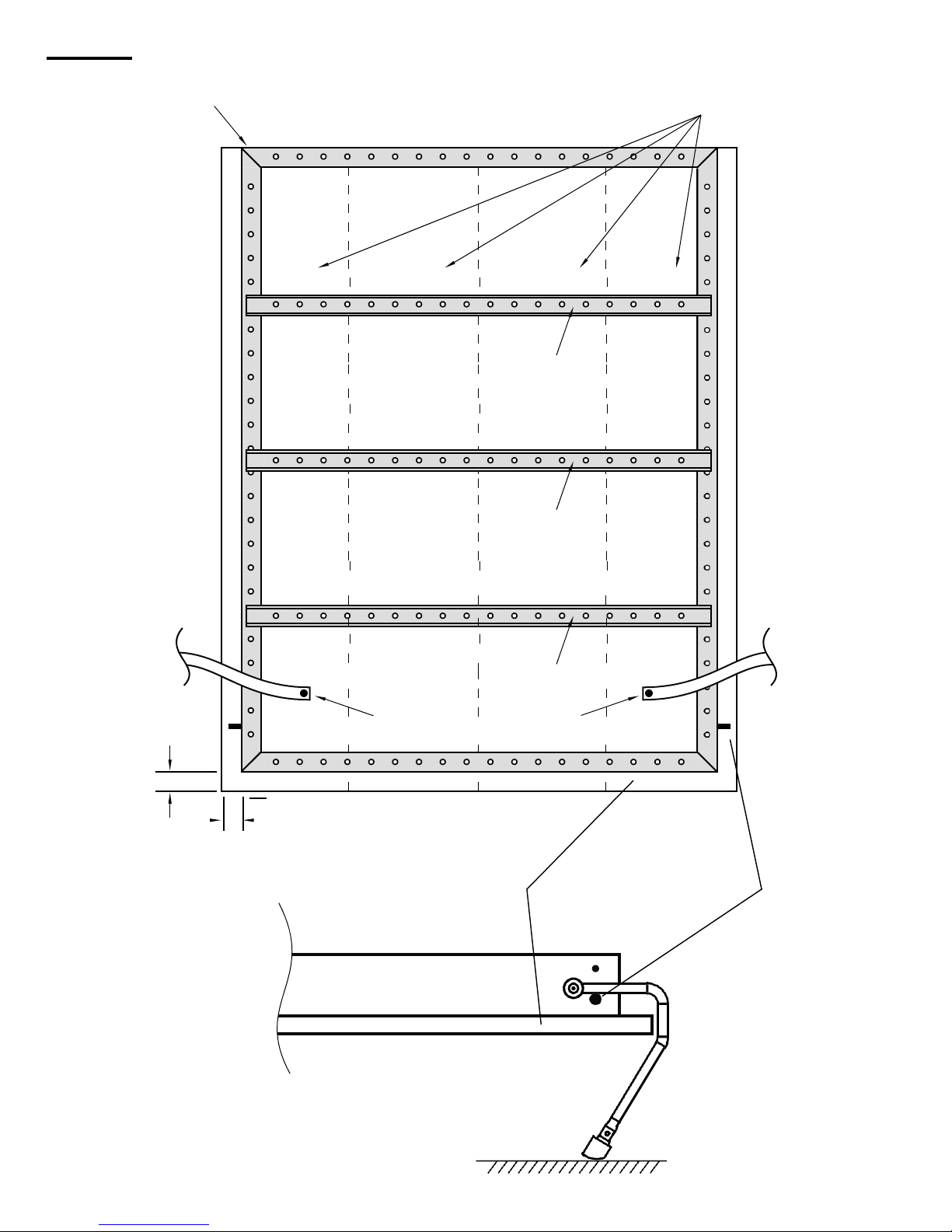
1: Lay the Bed Face Panels down on a non-scratch surface such as a carpet or
blanket.
2: Completely assemble the 4 Frame Sections with the corner brackets and the
3/16”x1/2” (M5x12mm) black bolts provided. Refer to Drawing 12 to properly place
the leg stops at outer right and left bottom holes at the foot of the bed frame.
3: Position the bed frame on the bed face panels. With the Head Frame section
flush with the head end of the Bed Face Panels. Refer to Drawing 10. Carefully
attach the Bed Frame so it is centered on the Bed Face Panels; you will have
approximately 15/16” (24mm) space from the bed frame to the panel edges right and
left and at the bed foot.
Note: It is very important to have the Bed Frame centered on the Bed Face Panels.
Any error will be noticed in the vertical sight lines when the bed is closed.
4: Three steel stiffeners are provided for all beds. These notched stiffeners
should be located and attached to divide the Bed Face length into four equal
sections. Use caution not to damage raised panels by putting screws in recessed
areas.
5: Attach the Nylon Web Strap approximately 18” (460mm) down from the foot of the
bed and 6” (150mm) in from the sides, for tucking in sheets. The Straps help secure
the mattress in the vertical position (see drawing 10).
STEP 6: Set the Lift Mechanism
Bolt in Hole #3 Drops
into this slot when Bed
Face Panel is loaded
Tension Arm
Bolt through Hole #2 to secure
Arm Lock
Hexagon Nut (Hole “A”)
Notch to rest against head of
Drawing 13.
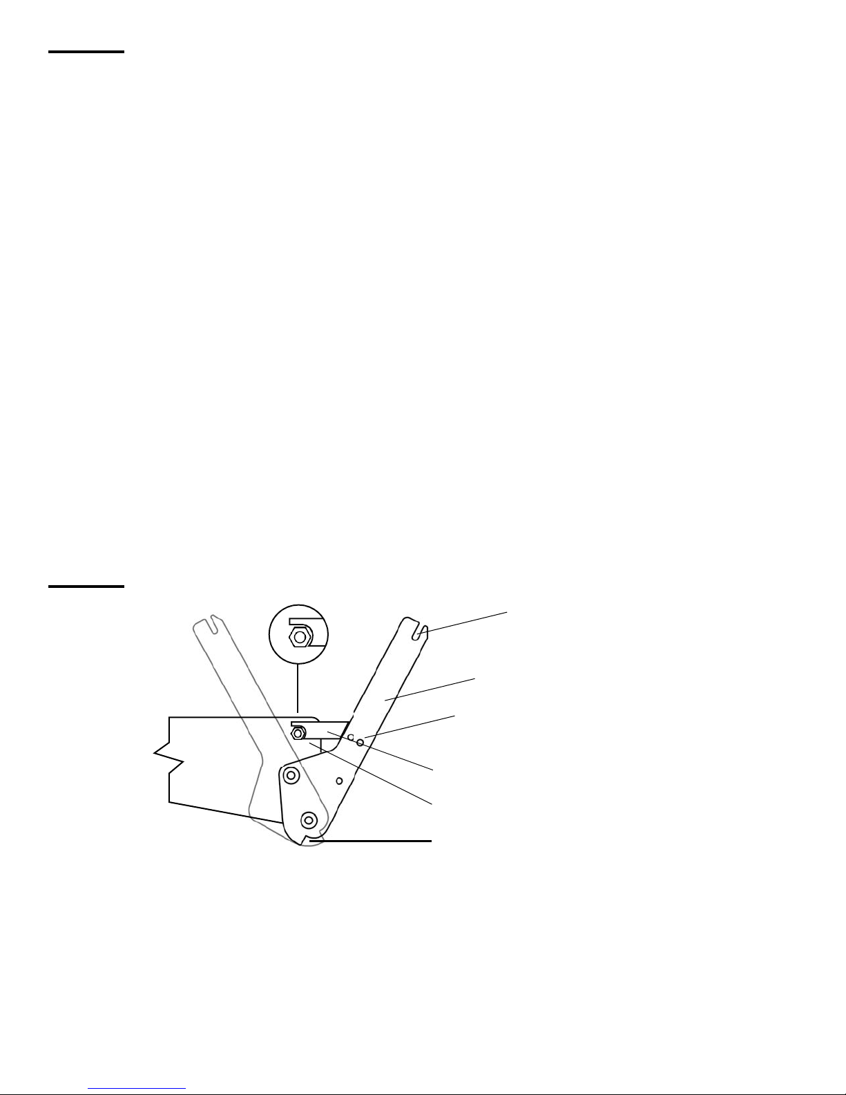
Holding one foot against the bottom front edge of the side panel and using the 13”
(330mm) PVC tube, lever the tension arm out until you can set the arm lock to the hex
nut at the hole A (see drawing 13.). This is the hex nut at the top front corner of the
mechanism.
Allen Bolt in Hole #1
Caution:
If possible have a helper assist in the setting of the mechanism and loading of the bed
face panel. DO NOT reach behind the tension arm when you are doing the setting
procedure.
13
Page 14
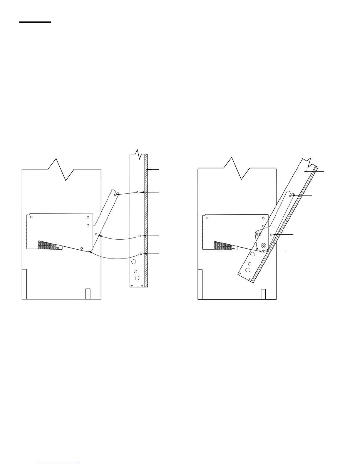
14
STEP 7: Install the Bed Face Panel Unit
Side Panel
1.
Insert Allen Head Bolts through Hole #1 (6 3/4” from end of side frame) on both left
and right side frames (see Drawing 14). Thread on 5/16” (8mm) Nylock nuts and
s
ecurely tighten.
2.
Insert two 5/16“ (M8x20mm) Hex Head Bolts from the outside of the frame through
Hole #3 and put 5/16” (8mm) Nylock Nuts on these bolts only finger tight at this time.
3.
Stand the Bed Face Panel in vertical position between the tension arms, lift evenly
until the bolt in Hole #3 drops in the slotted end of each tension arm. Gently tilt the
bed face toward you until the Allen Bolts in Hole #1 are completely seated in the
bottom notch of the tension arms. Insert the remaining 5/16” (8mm) Hex Head Bolts
through tension arms into Holes #2 and fasten with 5/16“ (8mm) Nylock Nuts;
securely tighten these and the nuts on Hole #3.
Bed Panel
Face
Head of Bolt
in Hole #3
Bolt Hole #2
Allen Bolt in
Hole #1
Drawing 14. Drawing 15.
4.
When all bolts are securely tightened, you may tilt the panel outward to approximately
Bolt Hole #2
Side Panel
Allen Bolt in
Hole #1 seated
in notch
45 degrees to release the arm locks. You will hear a click as they disengage.
Bed Panel
Unit Rail
Bolt Hole #3
seated in slot
Caution:
Hold the Face Panel securely, Do Not let it slam shut. Balance is not achieved until
the mattress is loaded in the bed.
Leveling of the bed cabinet is essential. Check the level both side to side and front to
back. Proper leveling will facilitate proper closure and exact sight lines of the fit of the
Face Panel to the Cabinet.
Page 15
15
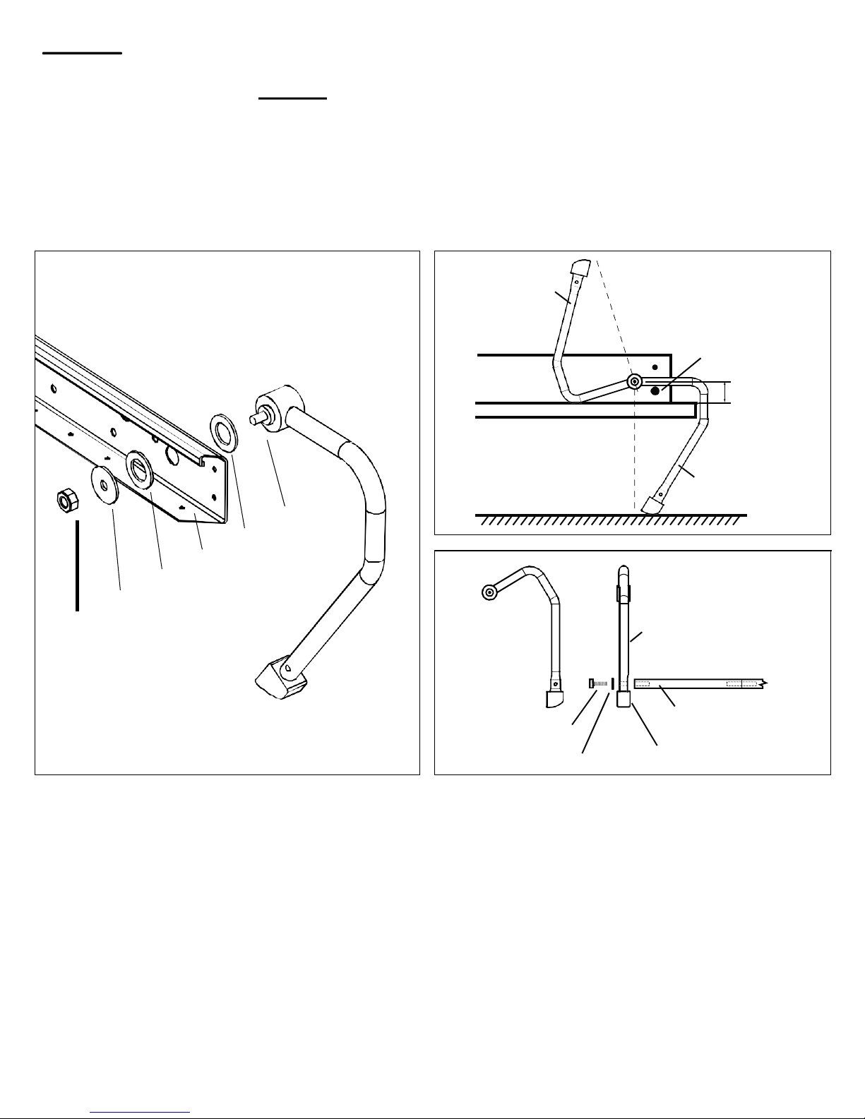
STEP 8: Install Handles - Legs - Mechanism Covers - Mattress
Drawing 18.
Steel Leg
Steel Leg Rod
1/4”-20 x 1 1/4” Bolt
Star Washer
Rubber Foot
1.
Position and secure handles for ease of operation. Measure down approximately 36”
(914mm) from the panel top to the top of the handles.
2.
Install legs with the washers on the inside of the Rails and the Nylon washer on the
outside. Tighten nut to have a small amount of friction when leg assembly is rotat
rom the up to down position.
f
ed
Steel Holding Washer
Nylock Nut
Steel Frame
Steel Filler Washer
Leg
Nylon Washer
Drawing 16.
Bed Closed Position
Bed Face Panel
Floor
Drawing 17.
Leg Stop
1 3/8” (35mm)
O.C. Leg Pivot Hole
Bed Open Position
Leg Assembly
3.
Install leg connector rod between legs and secure with 1/4”x1 1/4” (M4x32mm) Hex
head bolts and star washers. Be sure they are securely tightened so not to become
loose.
4.
Install the mattress and secure with previously installed Nylon Straps.
5.
Snap the powder coated steel mechanism covers in place - secure with #8x1 1/4”
(M4x32mm) black wood screws through the standoff on the backer plate.
Page 16
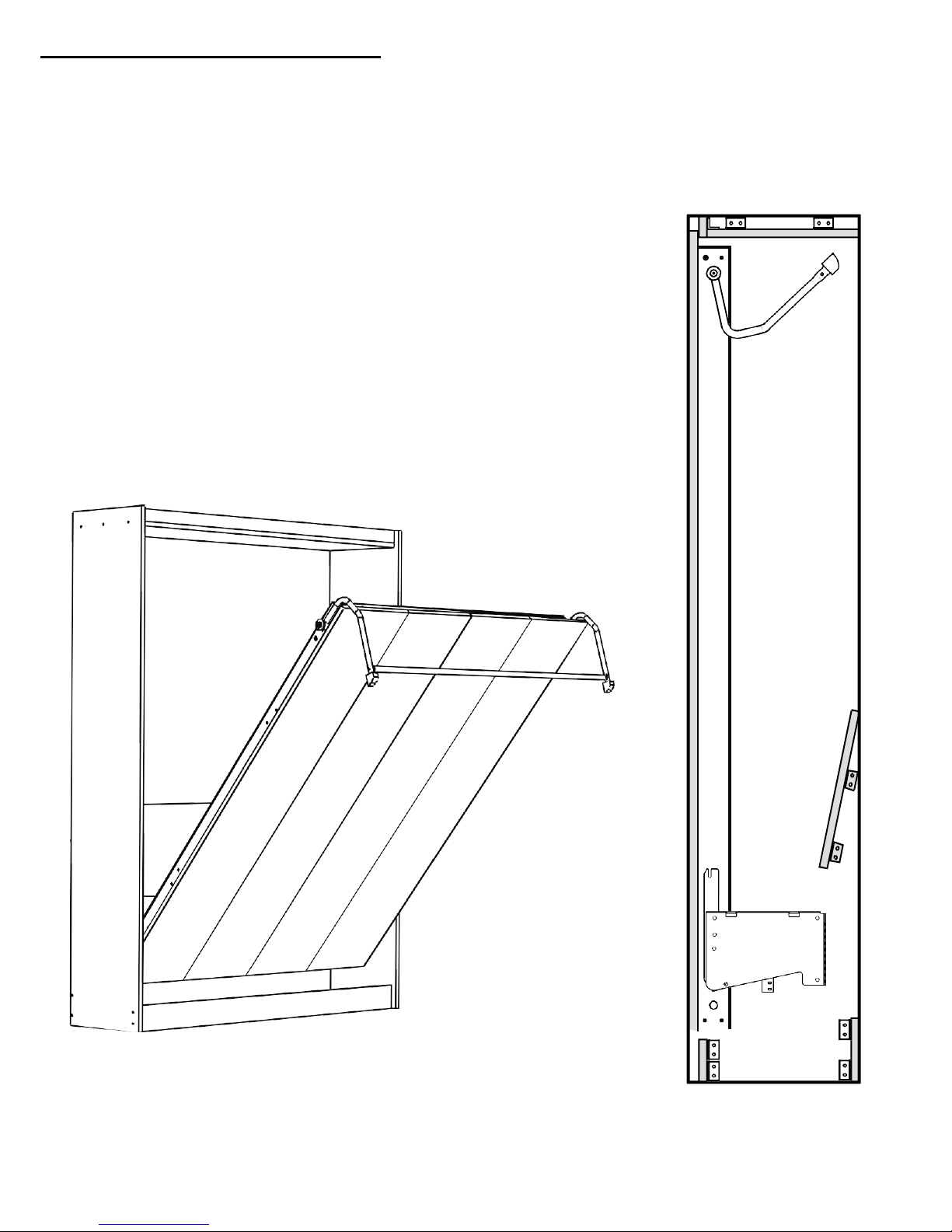
16
Complete Bed Assembly
Follow up to Initial Assembly
Check that the Bed Cabinet is level and square so the Bed
Face has equal clearance of the Cabinet on both sides, top
to bottom. If the Cabinet is leaning to one side, nudge it at
the floor level. If the top is uneven, place shims under the
Side Panels. If bed is too heavy to operate easily or slams
shut, remove the Bed Face Panel and add or subtract
springs. At this time, you may decide to use one more or
less spring(s) on the left or right side Lift Mechanism.
Right Side
Looking through Side Panel.
Page 17
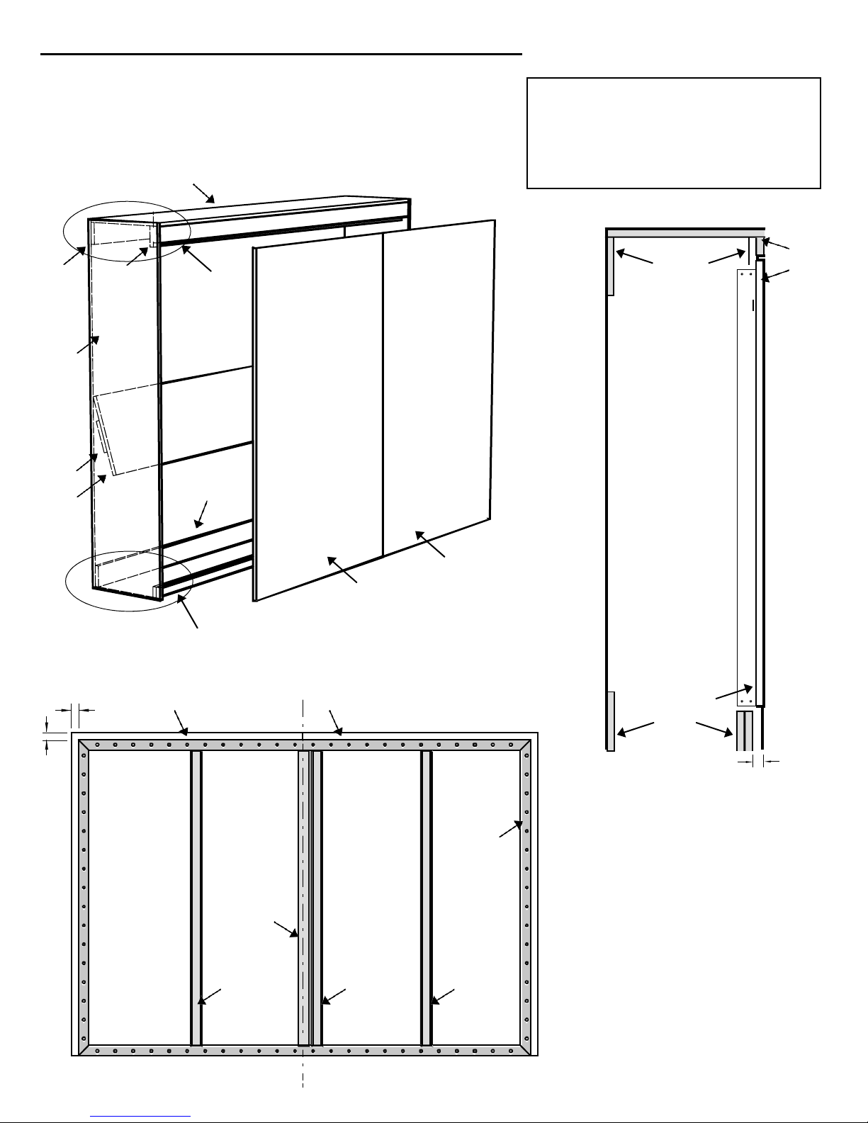
17.
6.
5.
(A)
1.
6. 7.
(B)
1.0” (25)
Bed Assembly (Horizont al Orientation)
10.
stiffener
stiffener
Frame
stiffener
(A)
6.
2.
5.
3.
4.
For Power Packs:
#SBLM:
Spring Balance Lift Mechanism
#SBLM-A:
Spring Balance Lift Mechanism Adjustable
4.
1.
1.0”
(25)
9.
8.
(B)
1.0”
(25)
6.
1.
Front
7.
1.
Foot
1.
1.
It is recommended to reinforce
the vertical seam where the
face panels meet with a 3/4”x3”
(19 x76mm) wood stiffener held
in place with wood screws to
the face panels. Use the steel
stiffeners as well; one next to
the wood stiffener and the
other two equally spaced.
Head
 Loading...