

Page 1
Installation Instructions
Read all instructions before installing this bin unit.
Failure to install the bin correctly may void warranty.
INSTALLATION VIDEO:
NZ: www.hideawaybins.co.nz/concelo_installation
AUS: www.hideawaybins.com.au/concelo_installation
Or scan the QR code...
FASTENER IDENTIFICATION:
WATCH FIRST
14 of 16mm
Surex
Screw
6 of 12mm
Surex
Screw
1 of 4mm
Allen Key
6 of 6G x 12mm
Self-tapping
Screw
FIG.6
New Zealand Australia
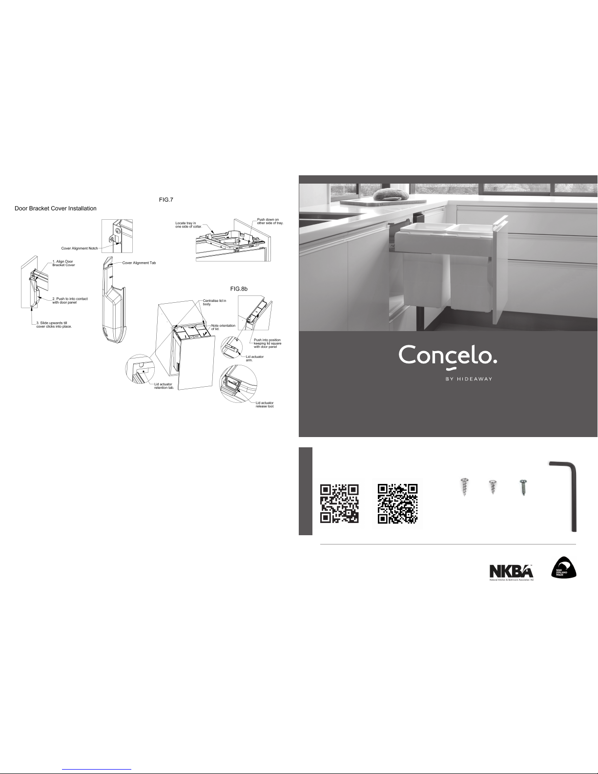
Step 8 – Fit the door bracket covers
Refer to Fig. 6
Step 9 – Install internal trays, buckets and liner holders
Refer to Fig. 7
Step 10 – Install Active Lid
• Refer to Fig. 8a & 8b
• Remove the lid actuator retention tab.
• Place lid on top of the liner holders and centralise. Fig 8a
NOTE: the orientation of the arrows on the lid should point into the cabinet.
• Close product until it is 100mm away from being fully closed. Fig 8b
• Push lid into body ensuring that it is kept square to the door panel. TIP: The body will keep the lid centralised in
the product.
• Push the lid as far back into the product as possible and hold in place. TIP: The lid will begin to lift when it is engaged
correctly with the internal mechanism. Some resistance may be felt as the lid engages with the internal mechanism.
While holding the lid in place, press the lid actuator arm inwards.
• If the lid is correctly engaged it will lift o the bins when the lid actuator arm is pushed inwards.
Step 11 – Removal of Active Lid
• To remove lid, open bin approx. 100mm and use Actuator Release Tool (or screwdriver) to push actuator in fully.
Lid will be released and slide out when bin is fully opened.
Installation complete
PLEASE ENSURE WARRANTY, CARE AND MAINTENANCE INSTRUCTIONS AND ACTUATOR RELEASE TOOL ARE
PASSED ON TO THE HOMEOWNER.
HIDEAWAY NEW ZEALAND
09 426 7456 / [email protected] / www.hideawaybins.co.nz
HIDEAWAY AUSTRALIA
1800 042 642 / [email protected] / www.hideawaybins.com.au
NOTE: Buckets and liner holders
should be in place.
FIG.8a
Page 2
Step 1 – Unpack carton
• Unpack collar rear panel and place to one side.
• Remove lid pack place to one side.
• Remove buckets / trays and place to one side.
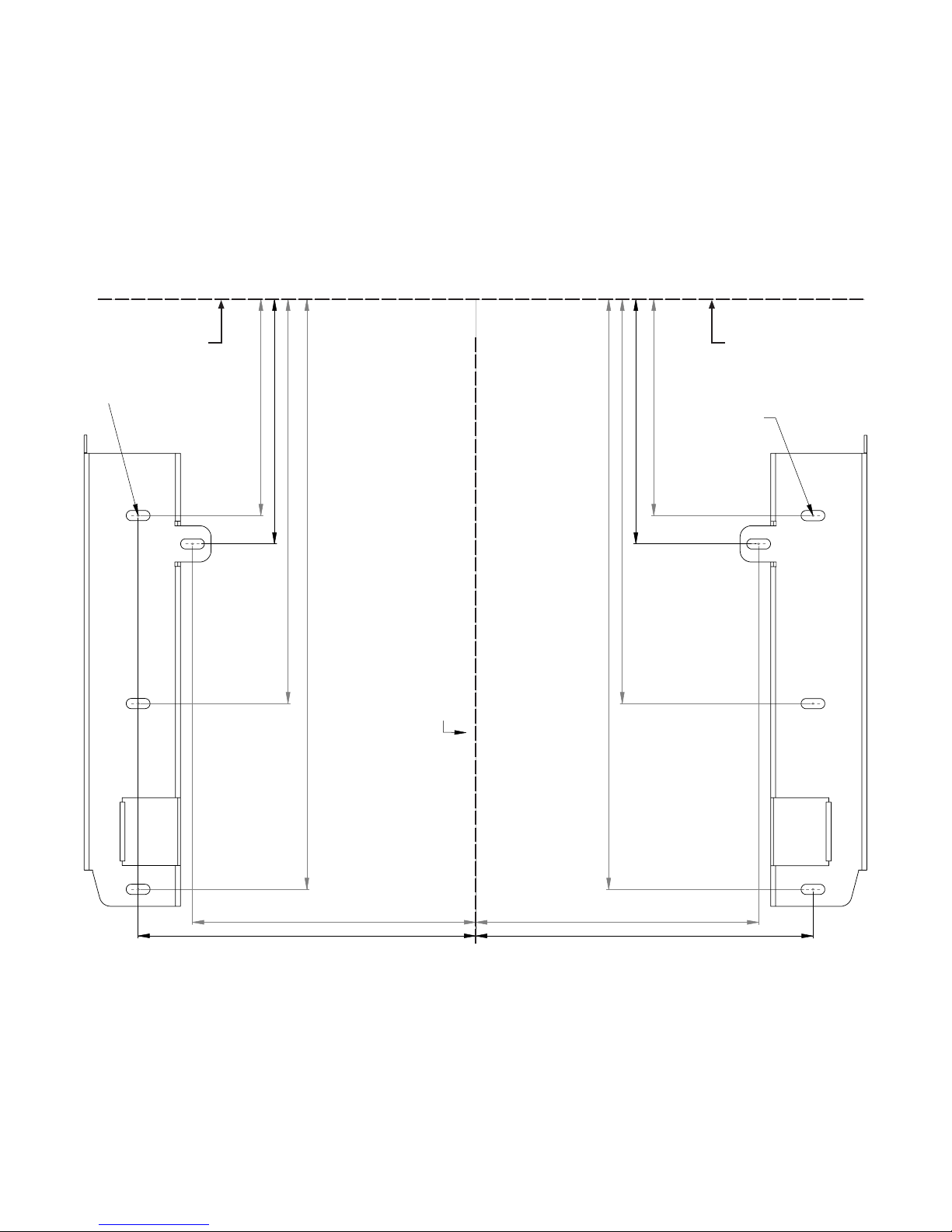
Step 2 – Pre-drill door panel
• If drilling the door panel using a CNC machine, drilling
positions are available as a CAD le from the Hideaway
Bins website.
• If drilling manually, refer to drilling template or drilling
dimensions.
• Mark a vertical centreline on the rear of the door panel.
• Mark a horizontal line indicating the top of the bin
body top reference. TIP: An allowance needs to be made
for the door overlap with the top of the carcase e.g. for a
16mm thick carcase material and 3mm gap between the
door panel and the bench top the horizontal line should be
(16-3) = 13mm down from the top edge of the panel.
• Align the door panel template with the lines as indicated
and mark the position of the mounting holes for the door
brackets through the paper. TIP: 3 screw locations
are required for each door bracket. An alternative location
for the top screw is indicated. This should only be used in
framed door situations but makes door adjustment more
dicult.
• Drill a 2mm pilot hole at each of the mounting locations.
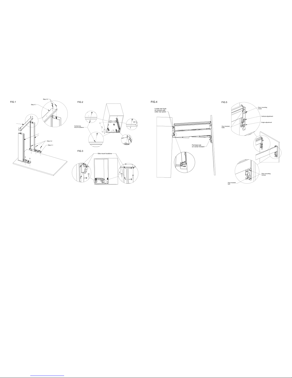
Step 3 – Install collar side sub assemblies
Refer to Fig. 1
3.1 - Position collar side sub assemblies
3.2 - Secure each using 12mm Surex screws provided
Step 4 – Install collar rear panel on to collar sides
Refer to Fig. 1
4.1 - Position collar rear panel as shown.
4.2 - Secure using 6G x 12mm self tapping screws.
NOTE: do not use impact driver
Step 5 – Install body sub assembly
Top and side mounting is recommended when possible, and
mandatory for commercial use.
Option 1 - Body installation, top or top and side mount:
For new kitchens, where possible, it is easiest to place the
carcase upside down on a bench while installing the body.
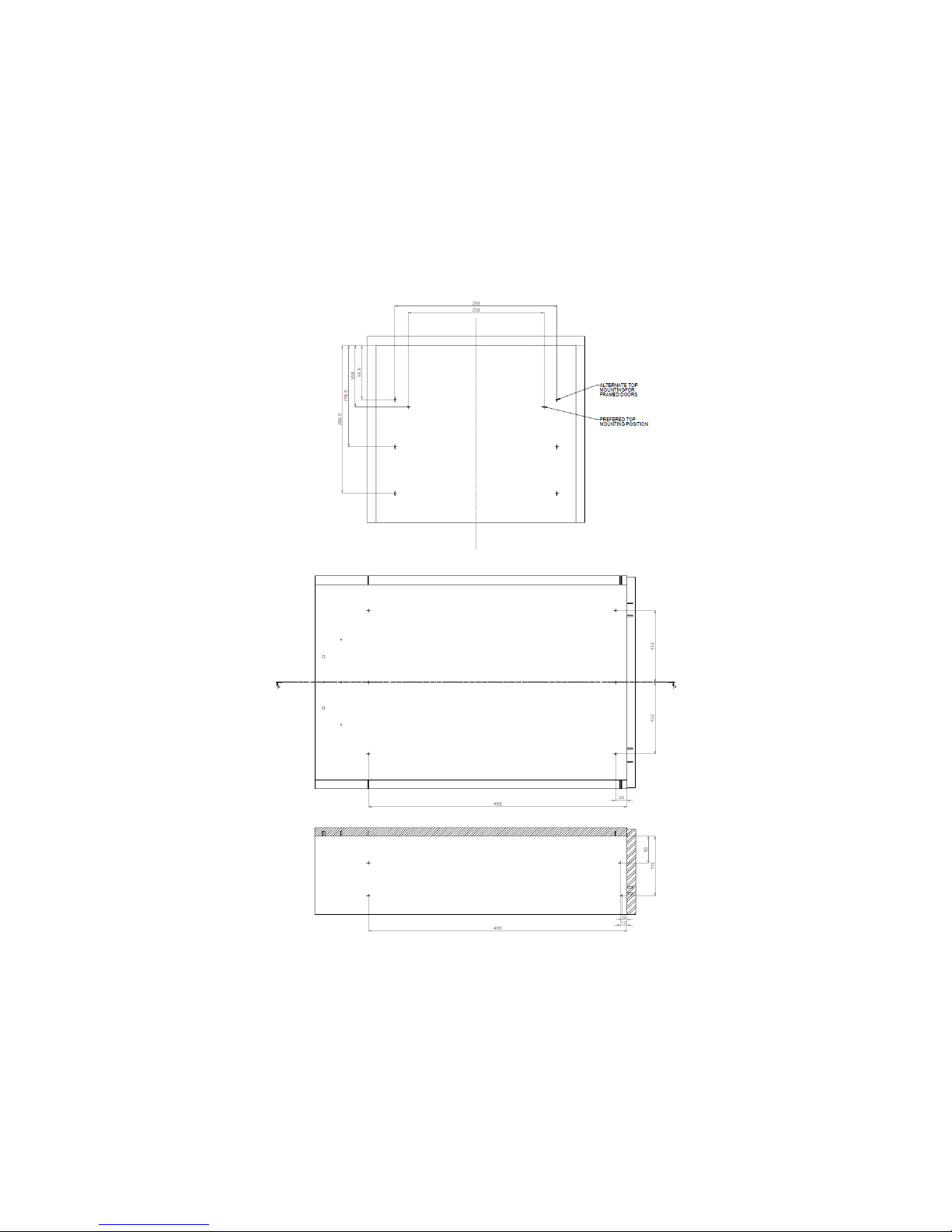
See drilling dimensions on back of door drilling template.
• Mark Centreline in top of carcase
• Mark 2 central top mount holes and drill 2mm pilot holes.
• Position body in carcase and secure using 2 of the 16mm
Surex screws provided. TIP: Align the front edge of the
body with the front of the carcase. If retrotting the
unit in an existing kitchen clamp the body to the top of the
carcase to hold it in place while securing fasteners.
• Drill pilot holes in other selected mounting locations using
the body as a guide
• Insert and tighten 16mm Surex screws in selected
mounting locations.
• If the carcase is upside down return it to an upright
position.
Option 2 - Body installation, side mount only:
Where possible partial top mounting to a rail in addition to
side mounting is recommended.
• Mark out all side mount holes referring to dimensions
provided on back of door drilling template. TIP: The centre
line of the side mount holes must be level to ensure the
product is level when installed.
• Predrill pilot holes for all 8 side mount holes.
• Position body in carcase and secure using 4 of the 16mm
Surex screws provided for each side.
Step 6 – Assemble collar and door panel to runners
• Position collar assembly as shown in g.4. TIP: Ensure that
runners are pulled forward, there is a black tab at the front
of the runner that can be pulled while holding the door
panel.
• Lower the door panel until a click is heard. TIP: The door
panel may need to be pushed down slightly
• Close the product and check that it is approximately level.
TIP: If the door panel is signicantly out of level it may
indicate that it is not clipped down fully on one side.
Step 7 – Adjust the door panel position
• Refer to Fig. 5
• Loosen the 6 door bracket bolts using the 4mm Allen key
provided.
• Adjust the door to be square and parallel to carcase and in
the correct vertical position using the adjustment cams.
• Tighten the 6 door bracket bolts.
• Loosen the 6 door mounting screws and adjust the
horizontal position of the door panel.
• Tighten the 6 door mounting screws.
Continue overleaf...
Collar Side Sub Assembly
Collar Rear
Panel
PLEASE WATCH THE INSTALL VIDEO BEFORE YOU BEGIN (link on the cover of these instructions)
Page 3
108
95.5
178.5
260.5
Alternate framed door
mounting point only
CR215
CR220
PANEL CENTRE LINE
BODY TOP REFERENCE
108
149
125
95.5
178.5
260.5
Alternate framed door
mounting point only
CR215
CR220
PANEL CENTRE LINE
BODY TOP REFERENCE
108
95.5
178.5
260.5
Alternate framed door
mounting point only
CR215
CR220
PANEL CENTRE LINE
BODY TOP REFERENCE
149
108
95.5
178.5
260.5
125
Alternate framed door
mounting point only
CR215
CR220
PANEL CENTRE LINE
BODY TOP REFERENCE
DOOR DRILLING TEMPLATE
BIN BODY TOP REFERENCEBIN BODY TOP REFERENCE
Page 4
DOOR PANEL DRILLING
CARCASE DRILLING
TOP VIEW
BACK FRONT
BACK FRONT
SIDE VIEW
 Loading...