

Page 1

15370 Barranca Parkway
Irvine, CA 92618
USA
.
VertX®
V100, V200 and V300
Installation Guide
© 2003 - 2011 HID Global Corporation. All rights reserved.
November 2011
6080-930 Rev A.1
Page 2

Contents
VertX V100, V200 and V300 Installation Guide
Introduction ............................................................................................................................................ 3
Parts List .......................................................................................................................................... 3
Product Specifications...................................................................................................................... 3
Cable Specifications ......................................................................................................................... 4
Overview ............................................................................................................................................ 4
Step 1 Preparations ................................................................................................................................... 5
1.1 What you need before getting started ................................................................................. 5
1.2 V100, V200, or V300 ........................................................................................................... 5
Step 2 Hardware Installation ..................................................................................................................... 6
2.1 Mounting ............................................................................................................................. 6
2.2 Wiring VertX ........................................................................................................................ 6
Contact Information .................................................................................................................................. 10
November 2011 Page 2 of 10
© 2003 - 2011 HID Global Corporation. All rights reserved.
Page 3
V100, V200 and V300
Quantity
VertX V100, V200 and V300 Installation Guide
Introduction
HID’s VertX open platform is flexible and scalable to permit ec onomic and high perf orm ance acces s control
solutions for a wide range of applications. The Ver tX units interconnec t through different sub-networks and
protocols to a standard TCP/IP network with the capability of a variety of applications.
The VertX Interface Panels ar e designed for control by a VertX V1000 Access Controller. T he V100
Door/Reader Interface panel controls two sets of door devices or one door with Card In/Card Out ( a reader
on both sides of the same door ). The V200 Input Monitor Interface panel m onitors as m any as 16 input
points. The V300 O utput Control Interfac e panel controls as m any as 12 output relays.
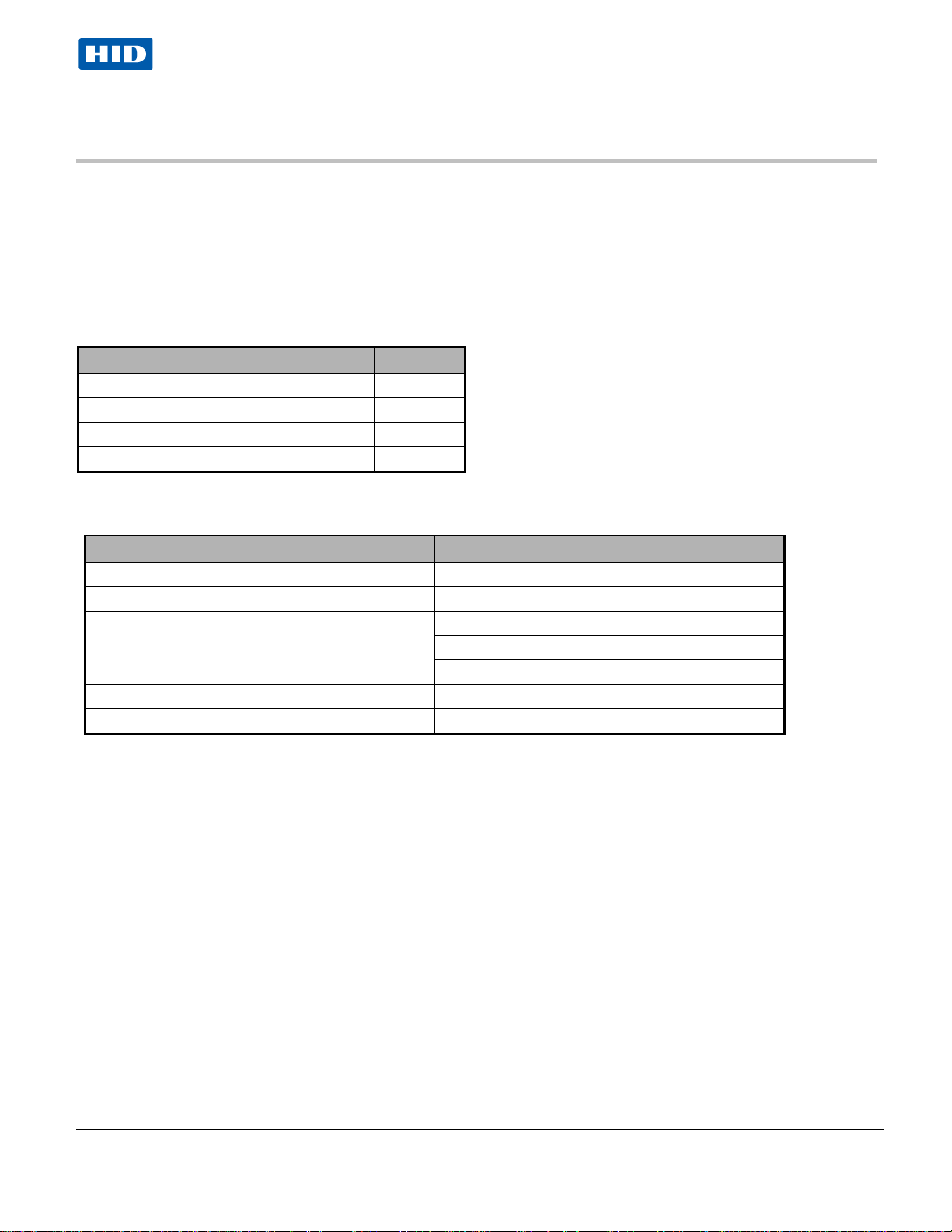
Parts List
Interface Panel 1
Mounting screws 4
2.2K EOL resistors 32
Quick Installation Guide 1
Note: VertX Interface panels require installing a V1000 Controller. See the V1000 Wiring Diagram Example.
Product Specifications
Description Specification
Power Supply 12-16VDC
Maximum Current at 12VDC per unit 1 Amp
Average operating current at 12VDC V100 - 450mA (with two R40 iCLASS Readers)
V200 - 60mA
V300 - 75mA
Operating temperature range 32°-120°F (0°-49°C)
Humidity 5% to 85% non-condensing
November 2011 Page 3 of 10
© 2003 - 2011 HID Global Corporation. All rights reserved.
Page 4

VertX V100, V200 and V300 Installation Guide
Cable Specifications
Cable Type Length Specification
RS-485 * 4000 feet (1220 m) to host
Input Circuits * 500 feet (150 m)
Output Circuits * 500 feet (150 m)
Wiegand
Power Supply
+12 VDC IN
• Minimum wire gauge depends on cable length and current requirements.
500 feet (150 m) to reader ALPHA 1299C, 22AWG, 9-conductor, stranded, overall shield.
---- Refer to your Power Supply Installation Guide.
Using Belden 3105A, 22AWG twisted pair, shielded 100Ω cable, or
equivalent.
2-conductor, shielded, using ALPHA 1292C (22AWG) or Alpha 2421C
(18AWG), or equivalent.
2-conductor, using ALPHA 1172C (22AWG) or Alpha 1897C (18AWG),
or equivalent.
Fewer conductors needed if all control lines are not used.
Overview
The following outlines what is required to installing VertX interfac e panels.
November 2011 Page 4 of 10
© 2003 - 2011 HID Global Corporation. All rights reserved.
Page 5

Terminating
Jumper
VertX V100, V200 and V300 Installation Guide
Step 1 Preparations
1.1 What you need before getting started
Prior to starting the installation, completely read this guide.
CAUTION: VertX Interface panels are sensitive to Electrostatic Discharges (ESD). Observe
precautions while handling the circuit board assembly by using proper grounding straps and
handling precautions a t all times.
1.2 V100, V200, or V300
1. If attaching the V100-Series panel to the end of the
RS-485 bus, install a terminating jumper to the In position
on the termination resistor pins, P8 on the cover (P10 on
the PCB) of the V100, V200 and V300.
2. If the V100-Series panel is being installed as part of an
array, or in a third party enclosure, follow the directions
provided by the Integrator or Dealer.
November 2011 Page 5 of 10
© 2003 - 2011 HID Global Corporation. All rights reserved.
Page 6

CAUTION: Connectors on the VertX devices are positioned to b e mirror images and are
VertX V100, V200 and V300 Installation Guide
Step 2 Hardware Installation
2.1 Mounting
1. Always mount the interface panels in a secure area.
2. Mount using the four mounting screws (provided) or other appropriate fasteners. Place the fasteners
in the corner holes of the base.
3. Stack the VertX devices with or without the cover. Do not remove the plastic base. Position the VertX
devices in such a way as to provide room for wiring, air-flow and cable runs.
CAUTION: Stacking the VertX devices without the cover risks the danger of breaki ng the LEDS
unless spacers are used for separation.
2.2 Wiring VertX
not interchangeable once t he installatio n is complet e. Therefore, you cannot unplug a
connector from one side and plug it into the corresponding connector on the other side.
1. Power and A la r m input c onnec tions (All VertX units):
Connect power by providing 12VDC to the P7 or P9 connector.
+12VDC goes to P7 Pin 1 or P9 Pin 8 and ground to P7 Pin 2
or P9 Pin 7. Batt Fail, AC Fail, and Tamper switch inputs are
wired as shown in the table. Connect the Bat Fail and AC Fail
inputs to battery low/failure and AC failure contacts provided on
the power supply. Connect the Tamper input to a tamper switch
on the enclosure.
Pin # P7
1 +12VDC
2 Ground
3 Bat Fail 4 Bat Fail +
5 AC Fail 6 AC Fail +
7 Tamper 8 Tamper +
November 2011 Page 6 of 10
© 2003 - 2011 HID Global Corporation. All rights reserved.
Page 7

VertX V100, V200 and V300 Installation Guide
2 Reader Connections (V100): Connect
Wiegand or clock-and-data interfaces to a
V100 using the connection table shown.
You can connect up to 10 signal lines for
the reader. Use as many of the signal
lines as required for your reader interface.
Note: Connect the data return line to the
same ground as the reader power if the
reader is not powered by the VertX units
12VDC.
Pin # V100 P1 V100 P4
1 Reader Power Shield Ground
2 Ground Hold
3 Data 0 / Data Beeper
4 Data 1 / Clock Red LED
5 Data Return Green LED
6 Green LED Data Return
7 Red LED Data 1 / Clock
8 Beeper Data 0 / Data
9 Hold Ground
10 Shield Ground Reader Power
3. RS-485 Connections –
Connect the V100 panel to the V1000 controller through the RS-485 cable. See the V1000 Quick
Install Guide for further information.
CAUTION: The V1000 RS-485 Ports 1 & 2 (P1) are a common bus and therefore can not have
panels with duplicate Interface Addresses assigned. The same is true of the V1000 RS-485,
Ports 3 & 4 (P4). For exa mpl e, two pane ls, both with Inter fac e Address 0 (factory default),
cannot be connected to Por ts 1 and/ or 2 (P1 ).
4. Interface Address – Set the interface address by turning the Address
dial. Ensure that the V100 Interface Address is documented in the
Hardware Installation Worksheet (found in the back of the HID VertX
V1000 Quick Install guide).
November 2011 Page 7 of 10
© 2003 - 2011 HID Global Corporation. All rights reserved.
Page 8

CAUTION: Some mag netic loc ks ex hibi t both high i nr ush c urr ent when a ctivate d and a hig h
VertX V100, V200 and V300 Installation Guide
5. Output Connections (All VertX units) – A ll Output connections are used
for general purpose controls. The following table shows where the various
outputs are located. Pin numbers shown use the convention “NO/C/NC”.
For example, Output 1, V2000: P3 Pin1 is NO (Normally Open,) Pin 2 is C
(Common,) and Pin 3 is NC (Normally Closed).
Note: Relays are dry contact rated for 2Amps @ 30VDC.
Output
number
1
2
3
4
5 P2 Pins 4/5/6
6 P2 Pins 7/8/9
7 P4 Pins 9/8/7
8 P4 Pins 6/5/4
9 P4 Pins 3/2/1
10 P5 Pins 9/8/7
11 P5 Pins 6/5/4
12 P5 Pins 3/2/1
V100 V200 V300
P3 Pins 1/2/3
Strike (lock)
Relay 1
P3 Pins 4/5/6
Aux Relay 1
P6 Pins 6/5/4
Strike (lock)
Relay 2
P6 Pins 3/2/1
Aux Relay 2
P3 Pins 2/3/4 P1 Pins 1/2/3
P6 Pins 3/2/1 P1 Pins 4/5/6
P1 Pins 7/8/9
P2 Pins 1/2/3
instantaneous break voltage when de-ene rgi zed due to magn etic fie ld c olla pse . It is
recommended you use of a snubber circuit across the c ontro lli ng re la y te rmi nal s to pr otec t the
controlling relay c ontac ts. Go to
support.hidglobal.com, see Solution 891 - How do I wire a High
In-Rush Current locking device to V er tX/ Edge /E dge Sol o?.
6. Input Connections (All V100-Series devices) – Input connections are analog inputs used for a
combination of specific functions such as Request-to-Exit (REX), Door monitor, etc. They can also be
used as general purpose monitoring. Connect one side of the switch or contact to the + (plus) lead and
the other to the – (minus) lead. The following table shows where the inputs are located. Pin numbers
shown on the cover use the convention +/–.
The default REX input configuration is normally open (NO) unsupervised (no EOL resistors).
However, the default door switch (DS) configurati on is Norm all y Cl ose d (NC), unsup er vised (no
EOL resistors).
All other input points are defaulted for NO switches and are unsupervised (no EOL resistors).
November 2011 Page 8 of 10
© 2003 - 2011 HID Global Corporation. All rights reserved.
Page 9

Except for the door monitor, all other
inputs default to NO
VertX V100, V200 and V300 Installation Guide
Any input can be configured as NO or NC, as well as unsupervised or supervised. They can be configured
for supervisory resistors of 1K – 6K Ohm. The setup of supervised inputs should be done during
configuration of the VertX devices via the host
Example: Input 1, V1000 is: P14 Pin1 is + and Pin 2 is -.
Supervised inputs can be configured for:
, unsupervised:
Input Number V100 V200 V300
1 P2 Pins 1/2 Door Monitor P1 Pins 1/2 P6 Pins 2/1
2 P2 Pins 3/4 REX input P1 Pins 3/4 P3 Pins 1/2
3 P5 Pins 4/3 Door Monitor P1 Pins 5/6 P7 Pins 8/7 Tamper
4 P5 Pins 2/1 Rex Input P1 Pins 7/8 P7 Pins 6/5 AC Fail
5 P7 Pins 8/7 Tamper P1 Pins 9/10 P7 Pins 4/3 Batt Fail
6 P7 Pins 6/5 AC Fail P2 Pins 1/2
7 P7 Pins 4/3 Batt Fail P2 Pins 3/4
8 P2 Pins 5/6
9 P4 Pins 10/9
10 P4 Pins 8/7
11 P4 Pins 6/5
12 P4 Pins 4/3
13 P4 Pins 2/1
14 P5 Pins 6/5
15 P5 Pins 4/3
16 P5 Pins 2/1
17 P7 Pins 8/7 Tamper
18 P7 Pins 6/5 AC Fail
19 P7 Pins 4/3 Batt Fail
November 2011 Page 9 of 10
© 2003 - 2011 HID Global Corporation. All rights reserved.
Page 10

Americas
HID
support:
sales:
main:
sales:
telephone:
fax number: 949 732 2120
Europe, Middle East and Africa
HID
support
sales:
telephone
fax number: +44 1440 714 840
Asia-Pacific
HID Asia Pacific Ltd. (Hong Kong)
support
sales:
telephone
fax number: (852) 3160 4809
VertX V100, V200 and V300 Installation Guide
Contact Information
Global (Californ ia , USA)
support_na@hidvertx.com
sales@hidvertx.com
949 732 2000
800 210 4744
800 237 7769
Corporation, Ltd. (Haverhill, UK)
: support_emea@hidvertx.com
salesemea@hidvertx.com
: +44 1440 714 850
: support_APAC@hidvertx.com
salesapac@hidvertx.com
: (852) 3160 9800
November 2011 Page 10 of 10
© 2003 - 2011 HID Global Corporation. All rights reserved.
 Loading...