


15370 Barranca Parkway
Irvine, CA 92618
USA
™
VertX EVO
V2000
Installation Guide
© 2003 - 2011 HID Global Corporation. All rights reserved.
April 2012
Document Number: 72000-901 Rev A.2

VertX EVO V2000 Installation Guide, 72000-902, rev A.2
Contents
Introduction ................................................................................................................................................. 3
Parts List .......................................................................................................................................... 3
Product Specifications...................................................................................................................... 3
Cable Specifications ......................................................................................................................... 3
Overview ...................................................................................................................................................... 4
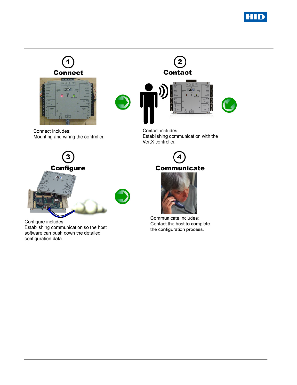
Step 1 Connect ........................................................................................................................................ 5
1.1 What you need before getting started ................................................................................... 5
1.2 V2000 .................................................................................................................................... 5
1.3 Mounting Instructions............................................................................................................. 5
1.4 Wiring VertX EVO .................................................................................................................. 6
Step 2 Contact ......................................................................................................................................... 9
2.1 Discovery Client ..................................................................................................................... 9
2.1.1 Installation ................................................................................................................................ 9
2.1.2 Use ........................................................................................................................................... 9
2.2 Virtual Port ........................................................................................................................... 10
Step 3 Configure.................................................................................................................................... 10
3.1 VertX Communications ........................................................................................................ 10
3.1.1 Configuration GUI Login ......................................................................................................... 10
3.1.2 Basic Network Setup .............................................................................................................. 10
3.1.3 Host Communication Setup .................................................................................................... 10
3.1.4 Confirmation ........................................................................................................................... 11
Step 4 Communicate ............................................................................................................................. 11
Appendices ................................................................................................................................................ 12
Trouble-shooting ............................................................................................................................ 12
System Status....................................................................................................................................... 12
Supplemental Configuration ................................................................................................................. 12
Configure .............................................................................................................................................. 12
System Time ......................................................................................................................................... 12
Update System ..................................................................................................................................... 12
Battery Replacement ............................................................................................................................ 13
Network Defaults Jumper ..................................................................................................................... 13
Firewall ........................................................................................................................................... 14
Contact Information .................................................................................................................................. 14
Regulatory ................................................................................................................................................. 15
Configuration Checklist - Static .............................................................................................................. 16
VertX Installation Worksheet ................................................................................................................... A1
April 2012 Page 2 of 18
© 2003 - 2012 HID Global Corporation. All rights reserved.
VertX EVO V2000 Installation Guide, 72000-902, rev A.2
Description
Quantity
Introduction
HID’s VertX EVO open platform is flexible and scalable to permit economic and high performance access control
solutions for a wide range of applications. The VertX EVO V2000 interconnects through different sub-networks and
protocols to a standard TCP/IP network with the capabili ty of a variety of applic ations.
For example, the VertX EVO V2000 Reader Interface / Access Controller is a cost-effective method for two-way
communication using Ethernet between a computer and a V2000.
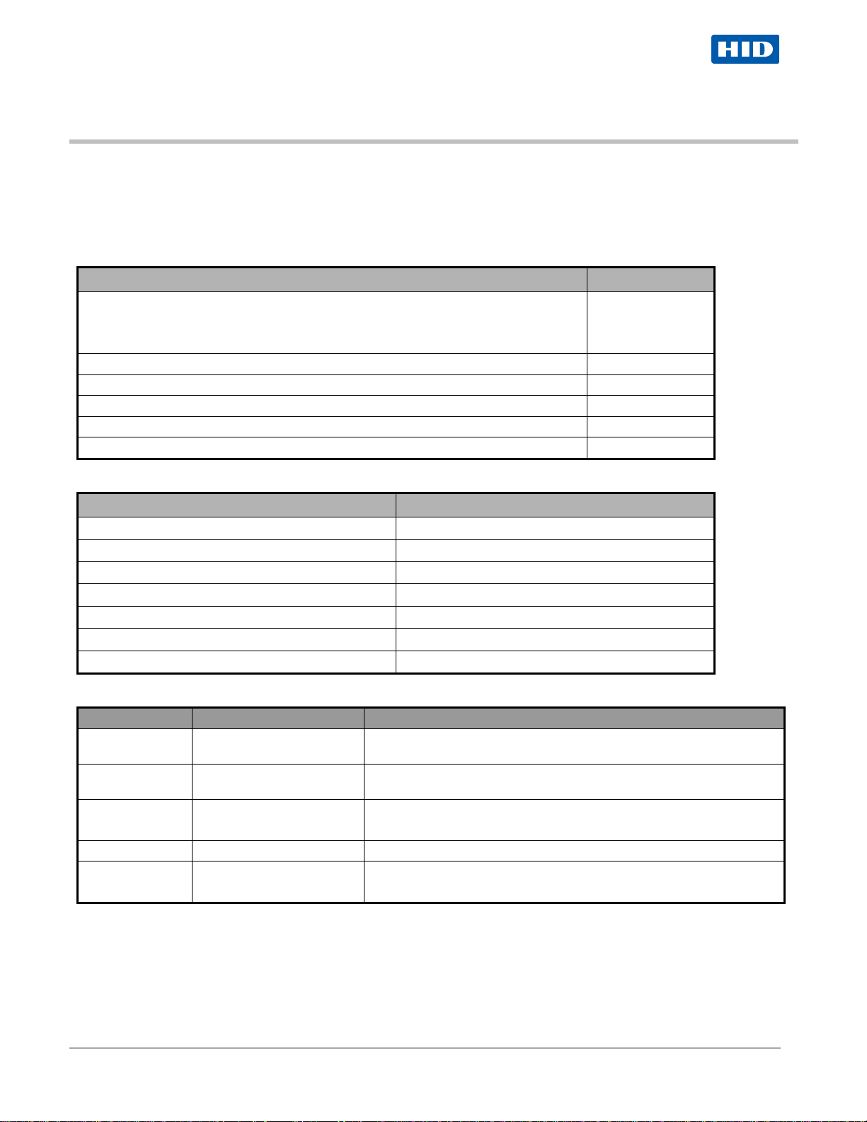
Parts List
VertX EVO™ V2000 (Reader Interface / Access Controller)
Note: Each VertX EVO V2000 has a plastic base and is covered with a plastic lid.
- Lithium Battery 1
- Mounting screws 4
- 2.2K EOL resistors 8 ea V2000
- Quick Installation Guide 1
- Installation Wiring Diagram Example 1
1 V2000
Product Specifications
Description Specification
Power Supply Input 12-24VDC
Maximum Current at 12-24VDC per Unit 1 Amp
Average Operating Current at 12VDC 625mA (with two R40 iCLASS Readers)
Reader Power Output 12VDC, 250mA each
Relay Outputs 30VDC, 2Amp, resistive
Operating Temperature Range 32°-120°F (0°- 49°C)
Humidity 5% to 85% non-condensing
Cable Specifications
April 2012 Page 3 of 18
Cable Type Length Specification
Input Circuits * 500 feet (150 m)
Output Circuits * 500 feet (150 m)
Wiegand
Ethernet 328 feet (100 m) Cat5, Cat5E, and Cat6
Power Supply
12-24 VDC IN
* Minimum wire gauge depends on cable length and current requirements.
500 feet (150 m) to reader ALPHA 1299C, 22AWG, 9-conductor, stranded, overall shield.
---- Refer to your Power Supply Installation Guide. Not Provided.
© 2003 - 2012 HID Global Corporation. All rights reserved.
2-conductor, shielded, using ALPHA 1292C (22AWG) or Alpha 2421C
(18AWG), or equivalent.
2-conductor, using ALPHA 1172C (22AWG) or Alpha 1897C (18AWG),
or equivalent.
Fewer conductors needed if all control lines are not used.
VertX EVO V2000 Installation Guide, 72000-902, rev A.2
Overview
The following outlines what is required to install VertX EVO V2000 controller.
April 2012 Page 4 of 18
© 2003 - 2012 HID Global Corporation. All rights reserved.
VertX EVO V2000 Installation Guide, 72000-902, rev A.2
Step 1 Connect
1.1 What you need before gettin g started
Prior to starting the installation, completely read this guide.
Reference the
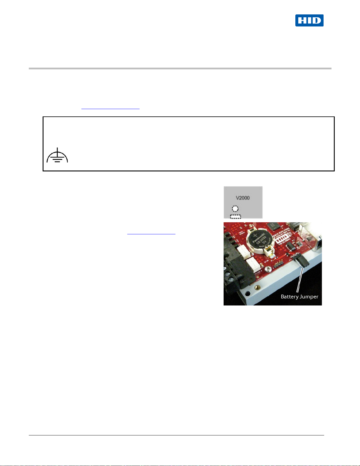
CAUTION:
VertX controllers are sensitive to Electrostatic Discharges (ESD). Observe precautions while handling the circuit
board assembly by using proper grounding straps and handling precautions at all times.
point is provided under two of the mounting screws (see silkscreen symbols).
Configuration Check List, page 16, and gather the information before proceeding with these instructions.
To further protect against the harmful effects of EMC and transients, a functional earth connection
1.2 V2000
Verify the battery jumper is installed in the ON position, P10 connector.
1.3 Mounting Instructions
1. Always mount the V2000 controller in t he protected.
2. Battery Installation (see Battery R eplacement)
a. Remove the cover.
b. Insert the battery (with the + (positive) side facing
upwards) under the prongs, lowering the opposite side
into place.
3. Mount using the four mounting screws (provided) or other
appropriate fasteners. Place the fasteners in the corner holes
of the base.
4. Position the VertX EVO devices in such a way as to pr ov ide
room for wiring, air-flow and cable runs.
5. Replace cover.
April 2012 Page 5 of 18
© 2003 - 2012 HID Global Corporation. All rights reserved.
VertX EVO V2000 Installation Guide, 72000-902, rev A.2
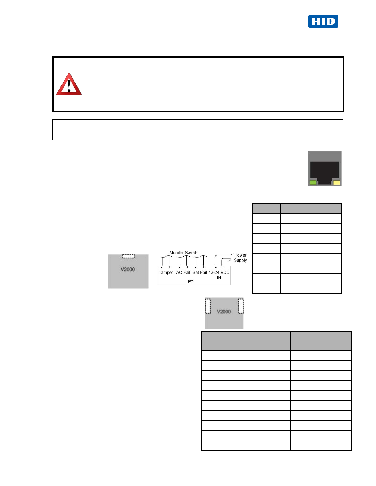
WARNING: VertX EVO V2000 is a NON-PoE device. DO NOT connect J1 (Ethernet port) to a
CAUTION: Connectors on the VertX EVO devices are positioned to be mirror images and are not
one side and plug it into the corresponding connector on the other side.
1.4 Wiring VertX EVO
PoE capable port. This applies to both direct PoE Power Sourcing Equipment (Endspan PSE)
and PoE injector (Midspan PSE) equipment. Not a l l PSE' s correctly detect Non-PoE-capable
devices, and such PSE's may not function as expected when connected to Non-PoE
equipment.
Installation Note: Carefully peel the attached Warning Label from the bottom of the unit and
leave the label attached to the unit's cover for future reference.
interchangeable once the installation is complete. Therefore, you cannot unplug a connector from
1. Network Connection: Connect the VertX EVO V2000 t o the network using a standard Cat5
network patch cable. Connect one end of the C at 5 network patch cable to the J1 (RJ-45)
connector on the V2000 and the other end to the networ k connection point (network jack,
hub, switch, or router) on your site.
Note: Two LED lights ex ist on the R J-45 connector. The green LED denotes Ethernet Activity
and the yellow LED denotes speed. When the Yellow LED is on, it indicates 100 Mbits per
second. Another LED in-board is a Duplex LED , indicating duplex communications are
available.
2. Power and Alarm input connections (All VertX EVO units): Connect
power by providing appropriate DC input to the P7 connector.
Appropriate DC input goes to Pin 1 and ground to Pin 2. Batt Fail, AC
Fail, and Tamper switch inputs are wired as show n in the t able.
Connect the Bat Fail and AC Fail inputs to battery low/f ailure and AC
failure contacts provided on the power supply. C onnect the T amper
input to a tamper switch on the
enclosure.
3. Reader Connections : Connect Wiegand or clock-
and-data interfaces to a V2000 using the
connection table shown. You can connect up to 10
signal lines for the reader. Use as many of the
signal lines as required for your reader interface.
Note: Connect the data return line to the same
ground as the reader power if the reader is not
powered by the VertX units.
Pin #
1 Reader Power Shield Ground
2 Ground Hold
3 Data 0 / Data Beeper
4 Data 1 / Clock Red LED
5 Data Return Green LED
6 Green LED Data Return
7 Red LED Data 1 / Clock
8 Beeper Data 0 / Data
9 Hold Ground
10 Shield Ground Reader Power
Pin # P7
1 12-24VDC
2 Ground
3 Bat Fail 4 Bat Fail +
5 AC Fail 6 AC Fail +
7 Tamper 8 Tamper +
V2000
P1
V2000
P4
April 2012 Page 6 of 18
© 2003 - 2012 HID Global Corporation. All rights reserved.
 Loading...