

Page 1
9292 Jeronimo Road
Irvine, CA 92618-1905
Quick Installation Guide
V1000 ACCESS CONTROLLER
PROPRIETARY INFORMATION. This document contains proprietary information which may not be duplicated,
published or disclosed to others, or used for any purpose without written permission from HID Corporation. 2004
© HID Corporation. All rights reserved.
Document Version 1.2
August 12, 2005
Document Number 6080-904D
Page 2

VertX V1000 (CS) Quick Installation Guide
Contents
Introduction .................................................................................................................................................... 3
Parts List .................................................................................................................................................. 3
Product Specifications ............................................................................................................................. 3
Cable Specifications ................................................................................................................................ 3
Overview .................................................................................................................................................... 4
Step 1 Preparations........................................................................................................................................... 5
1.1 What you need before getting started ........................................................................................ 5
1.2 V1000.......................................................................................................................................... 5
Step 2 Hardware Installation ............................................................................................................................ 5
2.1 Mounting Instructions.................................................................................................................. 5
2.2 Wiring VertX................................................................................................................................ 6
Step 3 Communications Configuration......................................................................................................... 10
3.1 Firewall Configuration............................................................................................................... 10
3.2 Computer to VertX Controller Connection................................................................................ 11
3.3 Windows TCP/IP Configuration ................................................................................................ 11
3.4 How to Edit Configuration Files ................................................................................................ 13
3.5 DHCP TCP/IP Addressing........................................................................................................ 14
3.6 Static TCP/IP Addressing ......................................................................................................... 16
3.7 Modem ...................................................................................................................................... 19
Step 4 Reboot and Test with the Central Station......................................................................................... 20
4.1 Calibrate Input........................................................................................................................... 20
Central Station Automation Provider Instructions........................................................................................ 21
Dice Corporation .................................................................................................................................... 21
GE MAS ................................................................................................................................................. 22
Bold Technologies ................................................................................................................................. 22
Contact Information.......................................................................................................................................... 22
Pre-Installation Checklist................................................................................................................................. 25
Installation Worksheet......................................................................................................................................A1
August 2005 Page 2 of 26
2004 © HID Corporation. All rights reserved
Page 3
VertX V1000 (CS) Quick Installation Guide
Introduction
VertX™ CS is the first family of access controllers designed specifically for alarm dealers for direct
connection to central stations. Because it was designed with central station in mind, VertX CS works with
software from leading central station automation providers, including Bold Technologies, DICE, and
GE MAS.
The V1000 is designed to control doors, reader contacts and relays through the RS-485 loop and any
combination of up to 32 Interface Panels (V100 Door/Reader Interface, V200 Input Monitor Interface and/or
V300 Output Control Interface). In addition, the V1000 Access Controller manages communications with the
central station automated software.
Parts List
Description Quantity
VertX™ V1000 Access Controller
Note: The V1000 controller has a plastic base and is covered with a Plastic or Mylar cover.
- Lithium Battery 1
- Mounting screws 4
- 2.2K EOL resistors 8
- HID Serial Adapter cable (P/N 70007) 1
- Quick Installation Guide 1
- Installation Wiring Diagram Example 1
Note: One or more VertX Interface panels are required.
1
Note: A modem and RS-232 Serial cable must be purchased separately if your installation includes a modem.
Product Specifications
Description Specification
Power Supply 12-16VDC
Maximum current at 12VDC per V1000 1 Amp
Average operating current at 12VDC 200mA
Operating temperature range 32°-122°F (0°-50°C)
Humidity 5% to 95% non-condensing
Cable Specifications
Cable Type Length Specification
RS-485 * 4000 feet (1220 m) to host
RS-232 6 inches (15.24 cm) HID Serial Adapter cable, P/N 70007 (included).
Input Circuits * 500 feet (150 m)
Output Circuits * 500 feet (150 m)
Ethernet 328 feet (100 m) Cat5, Cat5E, and Cat6
Power Supply
+12 VDC IN
* Minimum wire gauge depends on cable length and current requirements.
---- Refer to your Power Supply Installation Guide.
Using Belden 3105A, 22AWG twisted pair, shielded 100Ω cable, or
equivalent.
2-conductor, shielded, using ALPHA 1292C (22AWG) or Alpha 2421C
(18AWG), or equivalent.
2-conductor, using ALPHA 1172C (22AWG) or Alpha 1897C (18AWG), or
equivalent.
August 2005 Page 3 of 26
2004 © HID Corporation. All rights reserved
Page 4
VertX V1000 (CS) Quick Installation Guide
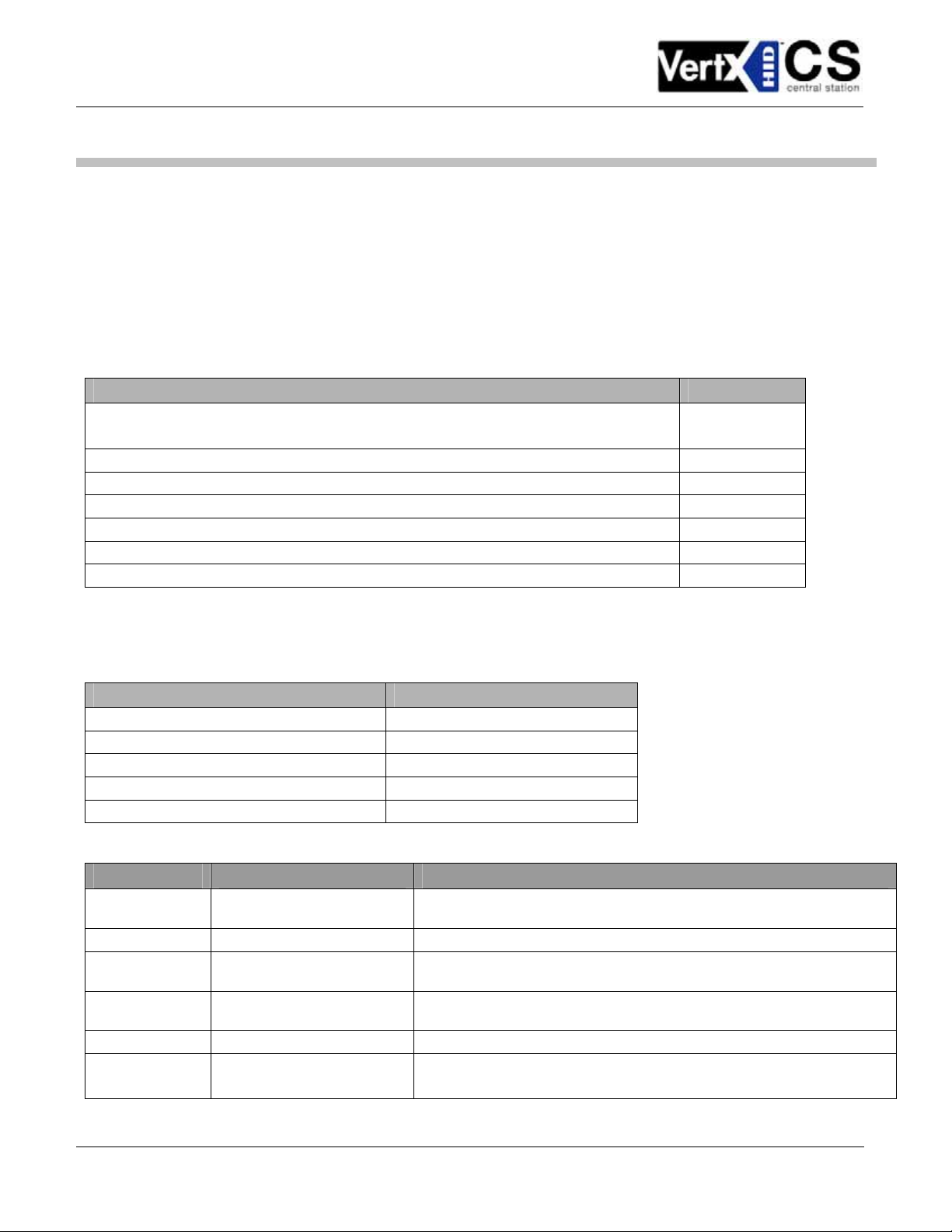
Overview
The following outlines what is required to install the V1000.
August 2005 Page 4 of 26
2004 © HID Corporation. All rights reserved
Page 5
VertX V1000 (CS) Quick Installation Guide
Step 1 Preparations
1.1 What you need before getting started
Prior to starting the installation, please completely read this guide.
CAUTION: The V1000 is sensitive to Electrostatic Discharges (ESD). Observe precautions while handling the circuit
board assembly by using proper grounding straps and handling precautions at all times.
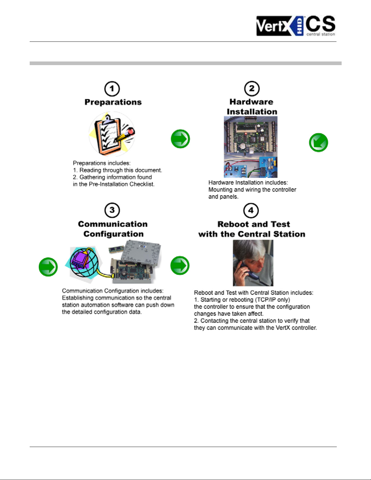
1.2 V1000
1. Remove the plastic or Mylar cover.
2. Verify the battery is installed. If the battery is not installed,
complete these steps:
a. Remove the button cell battery from the accessory kit.
b. Install the button cell battery (+ side up) in the battery
holder, BT1.
c. Verify that the battery jumper is in the ON position (or OUT
position on old covers), P15 connector (V1000).
d. Replace the plastic or Mylar cover.
3. Verify that the V1000 has a termination jumper installed on
each RS-485 Port; Port 1, 2, 3 and Port 4; depending on
which ports are not being used. The V1000 is shipped with
jumpers in the out positions.
Step 2 Hardware Installation
2.1 Mounting Instructions
1. The V1000 should always be mounted in a secure area.
2. Mount the V1000 using the four mounting screws (provided) or other appropriate fasteners. Place
the fasteners in the corner holes of the base.
3. The V1000 can be stacked with or without the cover. Do not remove the plastic base. Make sure you
position the V1000 in such a way as to provide room for wiring, air-flow and cable runs.
August 2005 Page 5 of 26
2004 © HID Corporation. All rights reserved
Page 6
VertX V1000 (CS) Quick Installation Guide
2.2 Wiring VertX
CAUTION: Connectors on the V1000 right and left sides are positioned to be mirror images and are not
interchangeable once the installation is complete. Therefore, you cannot simply unplug a connector from one
side of the board and plug it into the corresponding connector on the other side of the board.
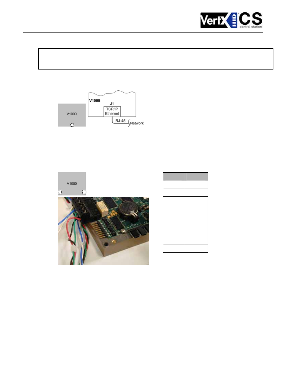
1. Network Connection: Connect the V1000 to the network using a standard Cat 5 network patch
cable. Connect one end of the Cat 5 network patch cable to the J1 (RJ-45) connector on the V1000
and the other end to the network connection point (network jack, hub, switch, or router) on your site.
2. Serial (RS-232) Adapter cable (P/N 70007) – The Serial Adapter cable is included with the V1000
controller.
The Serial Adapter cable is a six inch adapter that converts the 9 pin MTA header to a standard
DB-9 male connector. This adapter is to be utilized for attaching a standard serial modem cable
(not included) to the VertX. This will allow one of the approved external modems (listed in 3.7.1
Modem Setup Requirements, page 19) to be attached to the VertX V1000.
The table shows the P17 pin settings.
Pin # P17
1 DCD
2 RX
3
4 DTR
5 GND
6 DSR
7 RTS
8 CTS
9 RI
TX
August 2005 Page 6 of 26
2004 © HID Corporation. All rights reserved
Page 7
VertX V1000 (CS) Quick Installation Guide
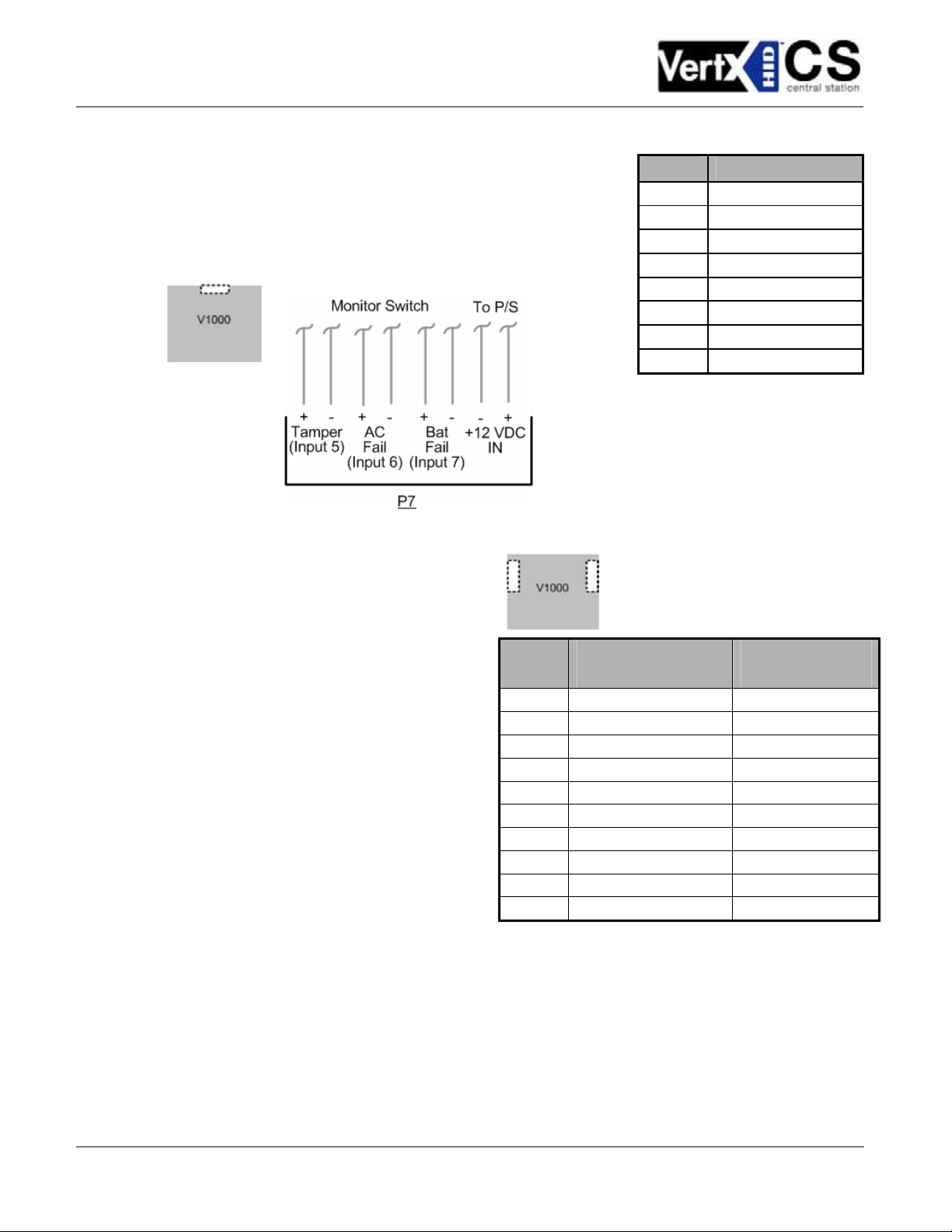
3. Power and Alarm input connections: Connect power by
providing 12VDC to the P7 connector. +12VDC goes to Pin 1
and ground on Pin 2. Bat Fail, AC Fail, and Tamper switch inputs
are wired as shown in the table. Connect the Bat Fail and AC Fail
inputs to battery low/failure and AC failure contacts provided on
the power supply. Connect the Tamper input to a tamper switch
on the enclosure.
Pin # P7
1 +12VDC
2 Ground
3 Bat Fail -
4 Bat Fail +
5 AC Fail -
6 AC Fail +
7 Tamper -
8 Tamper +
4. RS-485 Connections – The V1000 has
two - RS-485 connectors. The V1000 uses
the 10-pin, P3 and P4 for the RS-485
connections. Each RS-485 bus can support
a maximum of 16 V100-Series panels
using one or two ports.
Having two ports on each bus provides the
option of splitting each RS-485 bus into two
physical connections, allowing a total of
four physical connections for the two
busses.
RS-485 busses must be connected in a
daisy chain topology and not a star
topology.
Note: Each V1000 port and the end V100-
Series, whether it is single or a daisy-chain
connection, requires a separate termination
resistor jumper.
Pin #
1 A Not in use
2 B Not in use
3 Shield Shield
4 Not in use B
5 Not in use A
6 A Not in use
7 B Not in use
8 Shield Shield
9 Not in use B
10 Not in use A
V1000 P3
(port 1 and 2)
V1000 P4
(port 3 and 4)
August 2005 Page 7 of 26
2004 © HID Corporation. All rights reserved
Page 8
VertX V1000 (CS) Quick Installation Guide
CAUTION: The V1000 RS-485 Ports 1 & 2 (P1) are a common bus and therefore cannot have
panels with duplicate Interface Addresses assigned. The same is true of the V1000 RS-485,
Ports 3 & 4 (P4). For example, two panels, both with Interface Address 0 (factory default),
cannot be connected to Ports 1 and/or 2 (P1).
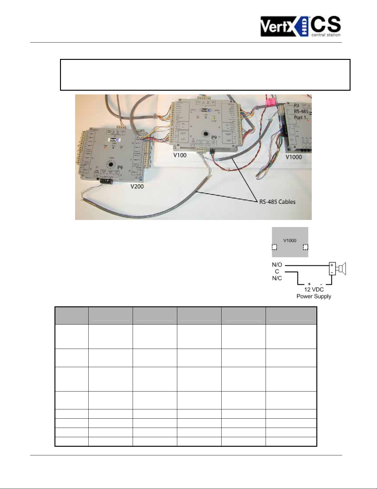
5. Output Connections – All Output connections are used for general
purpose controls. The following table shows where the various outputs
are located among the various VertX types. Pin numbers shown use
the convention “NO/C/NC”. For example, Output 1, V2000: P3 Pin1 is
NO (Normally Open) and Pin 2 is C (Common) and Pin 3 is NC
(Normally Closed).
Note: Relay contacts are rated for 2Amps @ 30VDC.
Output
number
1
2
3
4
5 P2 Pins 4/5/6
6 P2 Pins 7/8/9
7 P4 Pins 9/8/7
8 P4 Pins 6/5/4
V2000 V1000 V100 V200 V300
P3 Pins 1/2/3
Strike(lock)
Relay 1
P3 Pins 4/5/6
Aux Relay 1
P6 Pins 6/5/4
Strike (lock)
Relay 2
P6 Pins 3/2/1
Aux Relay 2
P14 Pins 2/3/4
P11 Pins 6/5/4
P3 Pins 1/2/3
Strike (lock)
Relay 1
P3 Pins 4/5/6
Aux Relay 1
P6 Pins 6/5/4
Strike (lock)
Relay 2
P6 Pins 3/2/1
Aux Relay 2
P3 Pins 2/3/4 P1 Pins 1/2/3
P6 Pins 3/2/1 P1 Pins 4/5/6
P1 Pins 7/8/9
P2 Pins 1/2/3
August 2005 Page 8 of 26
2004 © HID Corporation. All rights reserved
Page 9
VertX V1000 (CS) Quick Installation Guide
Output
number
9 P4 Pins 3/2/1
10 P5 Pins 9/8/7
11 P5 Pins 6/5/4
12 P5 Pins 3/2/1
V2000 V1000 V100 V200 V300
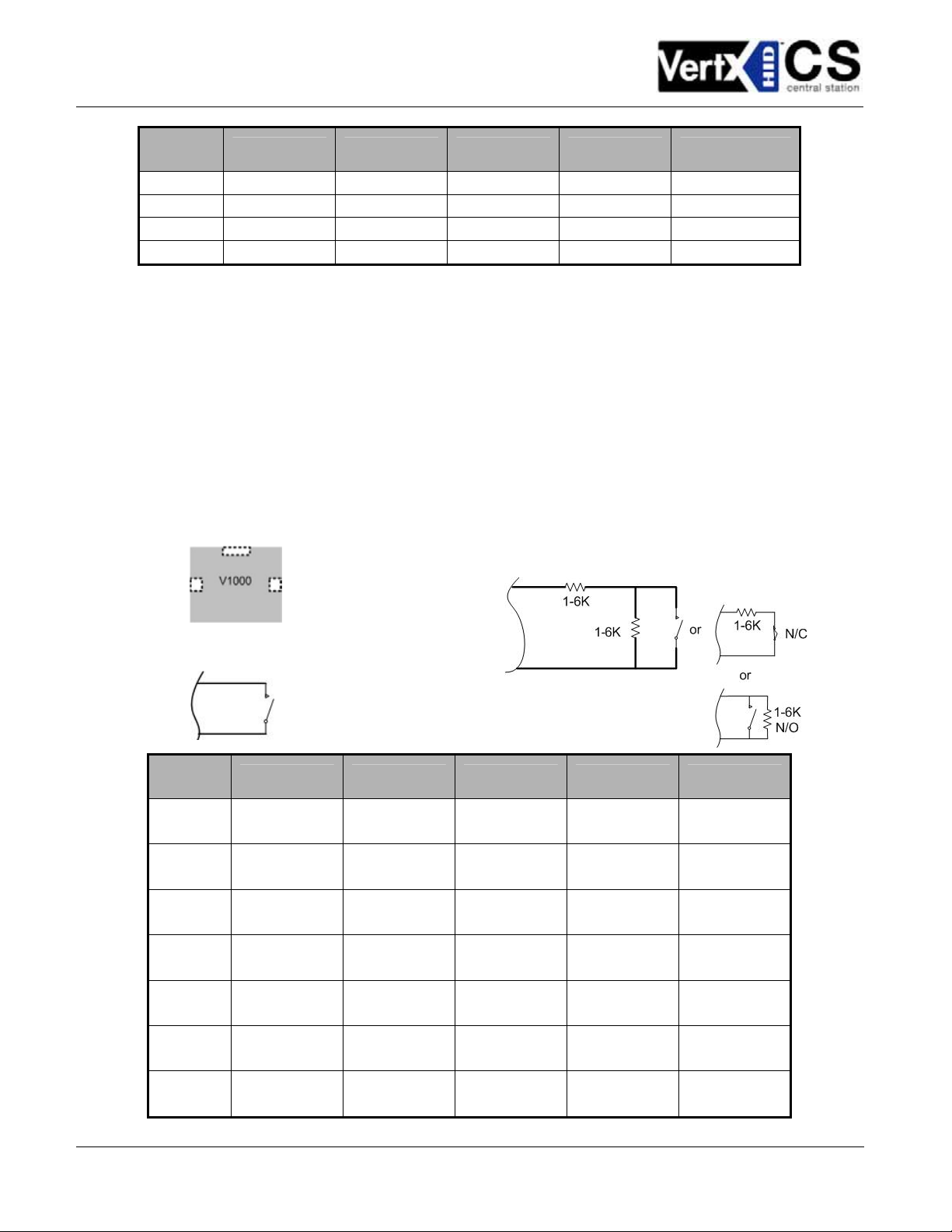
6. Input Connections – Input connections are used for a combination of specific functions such as
Request-to-Exit (REX), Door monitor, etc. They can also be used as general purpose monitoring.
Connect one side of the switch or contact to the + (plus) lead and the other to the – (minus) lead.
The following table shows where the inputs are located among the different VertX units. Pin
numbers shown on the cover use the convention +/–.
The default REX switch configuration is normally open (NO) unsupervised (no EOL resistors), while
the default door switch (DS) configuration is Normally Closed (NC) unsupervised (no EOL
resistors). All other input points are defaulted for NO switches and are unsupervised (no EOL
resistors).
Any input can be configured as a supervised input. They can be configured for resistors of 1K – 6K
Ohm. The setup of supervised inputs should be done during configuration of the VertX units via the
central station automation software (host) or by using the Calibrate Input tool, see section 4.1
Calibrate Input.
Example: Input 1, V1000 is: P14 Pin1 is + and Pin 2 is -.
Supervised inputs can be configured for:
All the default inputs will be:
Input
number
1
2
3
4
5
6
7
V2000 V1000 V100 V200 V300
P2 Pins 1/2
Door Monitor
P2 Pins 3/4
REX Input
P5 Pins 4/3
Door Monitor
P5 Pins 2/1
REX Input
P7 Pins 8/7
Tamper
P7 Pins 6/5
AC Fail
P7 Pins 4/3
Batt Fail
P14 Pins 1/2
P11 Pins 4/3
P7 Pins 8/7
Tamper
P7 Pins 6/5
AC Fail
P7 Pins 4/3
Batt Fail
P2 Pins 1/2
Door Monitor
P2 Pins 3/4
REX Input
P5 Pins 4/3
Door Monitor
P5 Pins 2/1
REX Input
P7 Pins 8/7
Tamper
P7 Pins 6/5
AC Fail
P7 Pins 4/3
Batt Fail
P1 Pins 1/2 P6 Pins 2/1
P1 Pins 3/4 P3 Pins 1/2
P1 Pins 5/6
P1 Pins 7/8
P1 Pins 9/10 P7 Pins 4/3
P2 Pins 1/2
P2 Pins 3/4
P7 Pins 8/7
Tamper
P7 Pins 6/5
AC Fail
Batt Fail
August 2005 Page 9 of 26
2004 © HID Corporation. All rights reserved
Page 10

VertX V1000 (CS) Quick Installation Guide
Input
number
8 P2 Pins 5/6
9 P4 Pins 10/9
10 P4 Pins 8/7
11 P4 Pins 6/5
12 P4 Pins 4/3
13 P4 Pins 2/1
14 P5 Pins 6/5
15 P5 Pins 4/3
16 P5 Pins 2/1
17
18
19
V2000 V1000 V100 V200 V300
P7 Pins 8/7
Tamper
P7 Pins 6/5
AC Fail
P7 Pins 4/3
Batt Fail
Step 3 Communications Configuration
This section describes the communications configuration.
There are three methods of communication possible on a V1000 controller:
• Dynamic Host Configuration Protocol (DHCP) TCP/IP Addressing
• Static TCP/IP Addressing
• Modem
Follow only the communication instructions that relates to your sites specific installation.
3.1 Firewall Configuration
If the VertX controller is being installed were it communicates through a firewall, then the firewall must be
configured to allow TCP data transfer on the specified port(s).
The port(s) that must be opened on the firewall for the VertX controller are the “
listen_port” specified in the CommCfg configuration file (/mnt/flash/TaskConfig/CommCfg) as well as the
“
Pre-Installation Checklist
.
If you are not familiar with configuring a firewall for the network, contact the Network/IT administrator or
manager.
CAUTION: If the firewall is not configured properly the controller will not be able to communicate with the
host.
connection_port” and
August 2005 Page 10 of 26
2004 © HID Corporation. All rights reserved
Page 11

VertX V1000 (CS) Quick Installation Guide
3.2 Computer to VertX Controller Connection
Note: This step is necessary if you are configuring your communications for DHCP or Static TCP/IP. If
configuring for Modem communications (skip to 3.7 Modem).
3.2.1 Hardware Requirements
The following outlines the hardware requirements for configuring a static TCP/IP connection.
• Computer with administration rights and an Internet browser, Internet Explorer 5.0 (or greater), or
equivalent.
• Ethernet cable
• Optional Hub – Required if primary communication channel is Ethernet.
Connect the computer to the VertX controller using an Ethernet cable.
3.3 Windows TCP/IP Configuration
Note: This step is only necessary if you are configuring your communications for DHCP or Static TCP/IP. If
configuring for Modem communications (skip to Error! Reference source not found. Error! Reference
source not found.).
Prior to proceeding with either DHCP or Static TCP/IP Configuration, you must configure your computers
TCP/IP configuration to communicate with the controller. We recommend that you document your current
Network Connections settings. These settings will provide you the ability to change your settings back to
their original configuration.
CAUTION: During the timeframe in which you have changed the TCP/IP settings on your computer, you will
not have access to the Internet or E-mail.
Depending on your operating system, follow one of the listed procedures.
• Windows XP Computers
• Windows 2000 Computers
• Windows Millennium Computers
August 2005 Page 11 of 26
2004 © HID Corporation. All rights reserved
Page 12

VertX V1000 (CS) Quick Installation Guide
3.3.1 Windows XP Computers
Set the computer IP address.
1. Click the Windows Start menu > Settings > Network Connections. The Network Connections
screen displays.
2. Double-click
3. Click Properties. The Local Area Connection Properties dialog displays.
4. Within the This connection uses the
following items: window, click Internet
Protocol (TCP/IP), and click Properties.
The Internet Protocol (TCP/IP) Properties
dialog displays.
5. Select the Use the following IP address
radio button. This action will enable the
fields IP address, Subnet mask and
Default gateway. Use the space bar to tab
between fields, the tab key will not work.
Local Area Connection. The Local Area Connection Status dialog displays.
6. Enter the IP address 10.19.4.130. If the
VertX board’s IP address is different than
what is shown, the computer IP address
must be modified accordingly. The two IP
addresses need to be in line with each other
and separated by one digit (for example:
10.19.4.130 is one digit greater than
10.19.4.129).
7. Enter the Subnet mask: 255.255.0.0.
8. Enter the Default gateway: 10.19.0.1.
9. Click OK.
10. Click Close to complete the computer configuration.
11. Restart your computer.
3.3.2 Windows 2000 Computers
1. Go to the Network screen by clicking the Start button. Click Settings and then Control Panel.
From there, double-click the Network Connections icon.
2. Select the Local Area Connection icon for the applicable Ethernet adapter (usually it is the first
Local Area Connection listed). Double-click the Local Area Connection. Click the Properties
button.
3. Select Internet Protocol (TCP/IP), and click the Properties button.
4. Select the Use the following IP address radio button. This action will enable the fields IP address,
Subnet mask and Default gateway. Use the space bar to tab between fields, the tab key will not
work.
August 2005 Page 12 of 26
2004 © HID Corporation. All rights reserved
Page 13

VertX V1000 (CS) Quick Installation Guide
5. Enter the IP address 10.19.4.130. If the VertX board’s IP address is different than what is shown, the
computer IP address must be modified accordingly. The two IP addresses need to be in line with
each other and separated by one digit (for example: 10.19.4.130 is one digit greater than
10.19.4.129).
6. Enter the Subnet mask: 255.255.0.0.
7. Enter the Default gateway: 10.19.0.1.
8. Click OK.
9. Click the OK button again to complete the computer configuration.
10. Restart your computer.
3.3.3 Windows Millennium Computers
1. Go to the Network screen by clicking the Start button. Click Settings and then Control Panel.
From there, double-click the Network icon.
2. On the Configuration tab, select the TCP/IP line for the applicable Ethernet adapter. Do not choose
a TCP/IP entry whose name mentions DUN, PPPoE, VPN, or AOL. If the word TCP/IP appears by
itself, select that line. Click the Properties button.
3. Click the IP Address tab and select Use the following IP address. Enter the IP address
10.19.4.130.
4. Now click the Gateway tab to enter the Installed Gateway content. Enter the Default Gateway
10.10.0.1. Click the OK button.
5. Click OK again. Windows may ask you for the original Windows installation disk or additional files.
Supply them by pointing to the correct file location, e.g., D:\win98, D:\win9x,
c:\windows\options\cabs, etc. (if “D” is the letter of your CD-ROM drive).
6. Restart your computer.
3.4 How to Edit Configuration Files
Before configuring a VertX controller to communicate through DHCP or Static TCP/IP Addressing, learning
the following conventions is necessary.
First, you must become familiar with editing conventions to successfully configure the VertX controller.
3.4.1 Conventions
The rules described are basic guidelines for editing the configuration files successfully.
• Lines beginning with “#” are comments and are ignored.
o The term “uncomment” means that you should remove the “#” symbol from the referenced line in
the configuration file.
o The term “comment” means to add a “#” symbol to the referenced line in the configuration file.
• White spaces must be space characters, and not tabs.
August 2005 Page 13 of 26
2004 © HID Corporation. All rights reserved
Page 14

VertX V1000 (CS) Quick Installation Guide
• In the Installer Tools, by default the Convert CRLF to LF box is checked, do not uncheck this checkbox
(found at the top of the Edit screen). This checkbox ensures that Carriage Returns are converted
correctly to line feeds for the VertX controller.
CAUTION: Currently there is minimal error checking on configuration data. If errors occur during
startup, you must verify that all configuration data is within valid ranges.
3.4.2 Accessing the Installer Tools
When configuring for a DHCP or Static TCP/IP connection, access the Installer Tools to edit the
configuration files.
1. Open your Internet Browser.
2. Enter the URL of the controller into the Address field.
• Static TCP/IP Communication,
• DHCP TCP/IP Communication,
Note: The URL is case sensitive and must be entered precisely as shown.
3. Click
. The Installer Tools menu will display.
Assigned VertX IP/InstallerTools.html
VertX_Controller.yourdomain.suffix/InstallerTools.html
3.5 DHCP TCP/IP Addressing
The VertX controller’s default communication configuration is DHCP addressing. When a DHCP address is
not provided, the controller will default to a static IP address of 10.19.4.129. When the controller successfully
obtains an IP address from a DHCP server, the V1000 communications will use the controller’s hostname.
The default hostname of a V1000 is “VertX_Controller.” Access the controller by completing the following
steps:
1. Connect an Ethernet cable from the controller connecting it to the computer or Ethernet Hub. See 3.2.1
Hardware Requirements.
2. Open your Internet Browser.
3. Enter the URL of the controller into the Address field.
August 2005 Page 14 of 26
2004 © HID Corporation. All rights reserved
Page 15

VertX V1000 (CS) Quick Installation Guide
The default DHCP URL is VertX_Controller.yourdomain.suffix/InstallerTools.html.
Domain names identify one or more IP addresses. For example, the domain name microsoft.com
represents about a dozen IP addresses. Domain names are used in URLs to identify particular Web
pages. Every domain name has a suffix, examples of a suffix include .com, .net, .org etc.
Note: If access to the controller is not successful, use the default static IP address (10.19.4.129).
CAUTION: For the DHCP communications to function properly the network must have a functioning DNS
(Domain Name Server) or you will be unable to communicate with the controller.
The following configuration files require editing to enable DHCP.
• /mnt/flash/TaskConfig/CommCfg
• /mnt/flash/TaskConfig/CommHosts
3.5.1 Configuration File Edits
The Setup Host Communication screen will take you to the Edit Configuration Files screen. The
configuration files described in this section will enable DHCP TCP/IP host communications. See sections 3.2,
3.3, and 3.4 for instructions on how to start.
Select a file from the list the appropriate configuration file and click Edit File. If you need to clear the
selection, click Clear Selection.
While following these instructions edit the circled areas shown.
Note: In addition to these configuration file edits, you may be interested in changing the “hostname”. See
/mnt/flash/etc/conf.d/hostname for instructions on changing the host name.
3.5.1.1 /mnt/flash/TaskConfig/CommCfg
From the Edit Configuration Files screen, then edit the
/mnt/flash/TaskConfig/CommCfg configuration
file.
1. Select
/mnt/flash/TaskConfig/CommCfg from the list.
2. Click Edit File. The Edit File window will display.
3. Enter the appropriate configuration data, see the Pre-Installation Checklist – Ref #4, page 25
the VertX controller to communicate to the host.
Example:
#
# commtask configuration parameters
# -----------------------------------------------------# Connect to host on startup (1=>yes)
connect_on_start 1
# If contacted by a host, maintain connection without callback (1=>yes)
maintain_host_connection 0
# Call the host machine on this port
connection_port 4070
# Listen on this port for host connection requests
listen_port 4050
, for
August 2005 Page 15 of 26
2004 © HID Corporation. All rights reserved
Page 16

VertX V1000 (CS) Quick Installation Guide
# If a connect attempt fails, wait this interval (~secs)
# before attempting to connect to the next host in CommHosts
reconnect_interval 15
# If no messages are received from the host within this interval (~min)
# then disconnect. (timeout = 0 => no timeout, continuous connection)
timeout 0
# Encrypt host communications (0=no, 1=yes)
use_encryption 0
# If a response to a host request is not received within this time (~secs),
# then disconnect.
message_response_time 20
3.5.1.2 /mnt/flash/TaskConfig/CommHosts
Finally, edit the
/mnt/flash/TaskConfig/CommHost configuration file to communicate with the central
station automation software (host).
This is the last configuration file requiring edits for Ethernet setup.
1. From the Edit Configuration Files screen, select
/mnt/flash/TaskConfig/CommHost from the list.
2. Click Edit File. The Edit File window will display.
For Static TCP/IP configuration edit the first two lines (lines 1 and 2 shown in the example).
Change “
host(s) in which you are working. See the Pre-Installation Checklist – Ref #5, page 25
10.19.4.130” and/or “VertXProductionTest” to include the IP Address or host name of the
.
Example of Ethernet primary only:
# commtask connection file
# cmid WaitTime MaxPings Username Script IPAddress(or Hostname) CommChannel(1-3)
1 1 2 * * 10.19.4.130 1
2 1 2 * * VertXProductionTest 1
#3 20 4 router1 Router 10.10.10.2 2
#4 20 4 modem1 Modem 10.19.4.131 2
3.6 Static TCP/IP Addressing
The following outlines hardware requirements and provides a detailed configuration procedure to aid you in
connecting to the V1000 through the static TCP/IP addressing configuration only.
See sections 3.2, 3.3, and 3.4 for instructions on how to start.
3.6.1 Configuration File Edits
The Setup Host Communication screen will take you to the Edit Configuration Files screen. The
configuration files available for editing will enable TCP/IP Static host communications using the Static TCP/IP
addressing communications method.
Select a file from the list and click Edit File. If you need to clear the selection, click Clear Selection.
August 2005 Page 16 of 26
2004 © HID Corporation. All rights reserved
Page 17

VertX V1000 (CS) Quick Installation Guide
While following these instructions edit the circled areas shown.
3.6.1.1 /mnt/flash/etc/conf.d/net.eth0
First, edit the
1. Select
/mnt/flash/etc/conf.d/net.eth0 configuration file.
/mnt/flash/etc/conf.d/net.eth0 from the list.
2. Click Edit File. The Edit File window will display.
Modify the following lines to match the controller’s specified configuration.
See the Pre-Installation Checklist – Ref #1, page 25
.
1. IP (IP Address)
2. NETMASK (Subnet Mask)
3. Gateway (Network Gateway)
Example:
# Network configuration:
# Valid boot protocols are "dhcp" (anything else implies "none").
# DHCP is configured to fail after a single server connection attempt,
# we will then revert to the statically configured address.
BOOTPROTO="dhcp"
DHCP_CLIENT="/bin/dhclient -1 -cf /etc/conf.d/dhclient.conf -lf /etc/dhclient.leases"
# Valid media types are "auto", "10baseT-HD", "10baseT-FD", "100baseTX-HD",
# "100baseTX-FD" and "" (nothing).
MEDIA="auto"
# If you are using DHCP the following variables will not be used.
IP="10.19.4.129"
NETMASK="255.0.0.0"
BROADCAST="10.255.255.255"
GATEWAY="10.19.0.1"
If using static
TCP/IP, change the
“
dhcp” to “none”.
3.6.1.2 /mnt/flash/etc/conf.d/hostname
From the Edit Configuration Files screen, continue by editing the
/mnt/flash/etc/conf.d/hostname
configuration file.
1. Select
/mnt/flash/etc/conf.d/hostname from the list.
2. Click Edit File. The Edit File window will display.
3. Modify the “
See the Pre-Installation Checklist – Ref #2, page 25
Hostname” (shown in the example as “V1000_Demo”) with the specified Hostname.
.
Example:
HOSTNAME="V1000_Demo"
3.6.1.3 /mnt/flash/etc/resolv.conf.def
From the Edit Configuration Files screen, edit the
August 2005 Page 17 of 26
2004 © HID Corporation. All rights reserved
/mnt/flash/etc/resolv.conf.def configuration file.
Page 18

VertX V1000 (CS) Quick Installation Guide
1. Select /mnt/flash/etc/resolv.conf.def from the list.
2. Click Edit File. The Edit File window will display.
3. Modify the “
aaitg.com”, “10.7.2.220” and “10.7.2.221” values with the specified DNS IP
addresses.
See the Pre-Installation Checklist – Ref #3, page 25
Example:
search aaitg.com\000
nameserver 10.7.2.220
nameserver 10.7.2.221
3.6.1.4 /mnt/flash/TaskConfig/CommCfg
From the Edit Configuration Files screen, then edit the
file.
1. Select
/mnt/flash/TaskConfig/CommCfg from the list.
2. Click Edit File. The Edit File window will display.
3. Enter the appropriate configuration data, see the Pre-Installation Checklist – Ref #4, page 25
the VertX controller to communicate to the host.
Example:
.
/mnt/flash/TaskConfig/CommCfg configuration
, for
#
# commtask configuration parameters
# -----------------------------------------------------# Connect to host on startup (1=>yes)
connect_on_start 1
# If contacted by a host, maintain connection without callback (1=>yes)
maintain_host_connection 0
# Call the host machine on this port
connection_port 4070
# Listen on this port for host connection requests
listen_port 4050
# If a connect attempt fails, wait this interval (~secs)
# before attempting to connect to the next host in CommHosts
reconnect_interval 15
# If no messages are received from the host within this interval (~min)
# then disconnect. (timeout = 0 => no timeout, continuous connection)
timeout 0
# Encrypt host communications (0=no, 1=yes)
use_encryption 0
# If a response to a host request is not received within this time (~secs),
August 2005 Page 18 of 26
2004 © HID Corporation. All rights reserved
Page 19

VertX V1000 (CS) Quick Installation Guide
# then disconnect.
message_response_time 20
3.6.1.5 /mnt/flash/TaskConfig/CommHosts
Finally, edit the
/mnt/flash/TaskConfig/CommHost configuration file to communicate with the central
station automation software (host).
This is the last configuration file requiring edits for Ethernet setup.
1. From the Edit Configuration Files screen, select
/mnt/flash/TaskConfig/CommHost from the list.
2. Click Edit File. The Edit File window will display.
Change “
host(s) in which you are working. See the Pre-Installation Checklist – Ref #5, page 25
10.19.4.130” and/or “VertXProductionTest” to include the IP Address or host name of the
.
Example of Ethernet primary only:
# commtask connection file
# cmid WaitTime MaxPings Username Script IPAddress(or Hostname) CommChannel(1-3)
1 1 2 * * 10.19.4.130 1
2 1 2 * * VertXProductionTest 1
#3 20 4 router1 Router 10.10.10.2 2
#4 20 4 modem1 Modem 10.19.4.131 2
3.6.1.6 Reconfigure your computer to the original Windows TCP/IP Settings
As discussed in 3.3 Windows TCP/IP Configuration, return your computers TCP/IP settings to their original
configuration.
3.7 Modem
The VertX controller will automatically answer incoming calls when an external serial modem is attached to
the RS-232 port 1.
3.7.1 Modem Setup Requirements
• External Modem (not included). The modem must be selected from the following approved HID modem
list:
o Zoom V.90 56 K Fax Modem, Model 2949 (external modem uses phone jack).
o U.S. Robotics V.92 56K Fax Modem, Model 5686 (external modem uses phone jack).
o Telular GSM 850/1900, Model 1C02A160 (external cellular modem).
• RS-232 Serial cable (not included)
• HID Serial Adapter cable (included with the VertX controller)
• AC electrical outlet or surge protector for supplying power to the modem
• Analog phone line included with the modem
• VertX controller
August 2005 Page 19 of 26
2004 © HID Corporation. All rights reserved
Page 20

VertX V1000 (CS) Quick Installation Guide
3.7.2 Physical Modem Setup
1. Connect the RS-232 Serial cable
(purchased separately) 25-pin connector
into the back of the modem.
2. Connect the other end of the RS-232 Serial
cable (9-pin connector) into the HID Serial
Adapter cable (P/N 70007). In addition,
connect the HID RS-232 Serial Adapter
cable into P17 RS-232 Port 1.
3. Connect one end of the phone cord
(included with the modem) into the TELCO
or LINE jack on the back of the modem and
plug the other end into an analog telephone
wall jack.
4. Plug the power adapter (included with modem) into a surge protector or electrical outlet. Make sure
you use the power adapter that came with the modem, as others may be of different voltages and
could damage your modem.
5. Turn on the modem. This is usually done by using a switch located next to the status lights. There
may also be a power switch located on the back of the modem.
Step 4 Reboot and Test with the Central Station
NOTE: Dependant on the central station automation software that is being utilized, proceed to Central
Station Automation Provider Instructions on page 21 before continuing with Step 4 Reboot and Test with the
Central Station.
Now that the V1000 is installed and configured.
1. Reboot the controller by removing and reconnecting the power supply to the controller. The
controller should be functional within 20-60 seconds.
2. Contact the Central Station to test communications.
4.1 Calibrate Input
The Calibrate Input tool is available for calibrating the input devices through the Installer Tools.
CAUTION: Only use the Calibrate Input tool if instructed to use it by the central station.
1. Find the Installer Tools by opening a browser and entering the controllers URL into the Address
field. See the Pre-Installation Checklist – Ref #5, page 25
.
August 2005 Page 20 of 26
2004 © HID Corporation. All rights reserved
Page 21

VertX V1000 (CS) Quick Installation Guide
2. Enter the following URL depending on your communication configuration:
• Static TCP/IP Communication,
Assigned VertX IP/InstallerTools.html
• DHCP TCP/IP Communication,
VertX_Controller.yourdomain.suffix/InstallerTools.html
3. Select Calibrate Input
4. If more information is required, click Installer Tools Documentation
Central Station Automation Provider Instructions
Dice Corporation
Perform the following steps if the central station uses Dice software.
1. Open your Internet Browser.
2. Enter the V1000 URL into the Address field. The URL is gathered from the central station.
See the Pre-Installation Checklist – Ref #5, page 25
.
3. Click
.
4. Click Edit Configuration Files
5. From the Edit Configuration Files screen, click Here I am. Then, click Edit File to modify the file.
6. From within the Here I am configuration file, on the third line, change 0 to 60.
BEFORE
AFTER
August 2005 Page 21 of 26
2004 © HID Corporation. All rights reserved
Page 22

VertX V1000 (CS) Quick Installation Guide
7. Click Save File, when complete and the change will become activated once the controller is
rebooted.
8. Close the browser window(s) when completed.
Continue to Step 4 Reboot and Test with the Central Station.
GE MAS
If using GE Monitoring Automation Systems (MAS) as a central station automation software, no additional
steps are necessary for configuring the V1000 controller.
Bold Technologies
If using Bold Technologies as a central station automation software, no additional steps are necessary for
configuring the V1000 controller.
Contact Information
HID Corporation
Web Site http://www.hidcorp.com
Main Phone (949) 598-1600
Sales (800) 210-4744
Technical Support (800) 237-7769
929274 Jeronimo Road, Irvine, CA 92618-1905
Fax (949) 598-1698
August 2005 Page 22 of 26
2004 © HID Corporation. All rights reserved
Page 23

VertX V1000 (CS) Quick Installation Guide
All National and local Electrical codes apply.
• This equipment is intended to be powered from a limited power source output of a
previously certified power supply.
• Changes or modifications not expressly approved by the party responsible for
compliance could void the user’s authority to operate the equipment.
Class A Digital Devices
FCC Compliance Statement: This equipment has been tested and found to comply with the limits for a
Class. A digital device, pursuant to part 15 of the FCC Rules. These limits are designed to provide
reasonable protection against harmful interference when the equipment is operated in a commercial
environment. This equipment generates, uses, and can radiate radio frequency energy and, if not installed
and used in accordance with the instruction manual, may cause harmful interference to radio
communications. Operation of this equipment in a residential area is likely to cause harmful interference in
which case the user will be required to correct the interference at his own expense.
Class B Digital Devices
FCC Compliance Statement: This equipment has been tested and found to comply with the limits for a
Class B digital device, pursuant to the limits for a Class B digital device, pursuant to part 15 of the FCC
Rules. These limits are designed to provide reasonable protection against harmful interference in a
residential installation. This equipment generates, uses, and can radiate radio frequency energy and, if not
installed and used in accordance with the instructions, may cause harmful interference to radio
communications. However, there is no guarantee that interference will not occur in a particular installation.
If this equipment does cause harmful interference to radio or television reception, which can be determined
by turning the equipment off and on, the user is encouraged to try to correct the interference by one or
more of the following measures:
• Reorient or relocate the receiving antenna.
• Increase the separation between the equipment and the receiver.
• Connect the equipment into an outlet on a circuit different from that to which the receiver is
connected.
• Consult the dealer or an experienced radio/TV technician for help.
August 2005 Page 23 of 26
2004 © HID Corporation. All rights reserved
Page 24

VertX V1000 (CS) Quick Installation Guide
Intentional Blank
August 2005 Page 24 of 26
2004 © HID Corporation. All rights reserved
Page 25

VertX V1000 (CS) Quick Installation Guide
Pre-Installation Checklist
Hardware
Name Source Part Number
Ethernet Cable
Computer with Web Browser
Hub (Optional)
Modem (Optional)
VertX Modem Cable (Optional) HID 70007
AC Electrical Outlet or Surge Protector (Optional)
Configuration Data
Doc
Ref
File Name/Data Configuration Data Collected Data
Bootproto (for DHCP)
IP Address
1 /mnt/flash/etc/conf.d/net.eth0
Netmask
Gateway
2 /mnt/flash/etc/conf.d/hostname Hostname
Domain Name for Search
3 /mnt/flash/etc/resolv.conf.def
DNS IP Address (Primary)
DNS IP Address (Secondary)
Connect_on_start
Maintain_host_connection
Connection_port
Listen_port
4 /mnt/flash/TaskConfig/CommCfg
Reconnect_interval
Timeout
Use_encryption
Message_response_time
Host Name (“john.abc.com”)
5 /mnt/flash/TaskConfig/CommHost
Host IP Address
Connection Type(s)
August 2005 Page 25 of 26
2004 © HID Corporation. All rights reserved
Page 26

VertX V1000 (CS) Quick Installation Guide
Intentional Blank
August 2005 Page 26 of 26
2004 © HID Corporation. All rights reserved
Page 27

VertX Installation Worksheet
Installation Worksheet
This installation worksheet is provided for you to have a historical record of your system settings. Complete
each appropriate field, and keep this worksheet in a safe location.
Record if the input is wired: 1) N/O or N/C, 2) Unsupervised or Supervised (resistor values), and 3) what
type of device is attached.
Record if output is wired: 1) N/O or N/C and 2) what type of device is attached.
V1000/V2000 Information:
Customer Name: Contact:
Installed Location: MAC Address:
Modem Model: RS232 Port #: Phone #:
Hostname: IP Address:
Tamper: AC Fail: BATT Fail:
Input 1: Input 2: Relay 1: Relay 2:
V100-Series Information (If V2000, there is a V100 at Interface Address 0 built-in):
Interface Address: (0-31)
Interface Type:
(V100, V200, V300, V2000)
Tamper: AC Fail: BATT Fail:
Reader 1: Reader 2:
Door Switch 1: REX 1: Door Switch 2: REX 2
Reader
Interface
V100 Door /
Strike Relay 1: Aux Relay 1: Strike Relay 2: Aux Relay 2:
Input 1:
Input 5: Input 6: Input 7: Input 8:
Input 9: Input 10: Input 11: Input 12:
Monitor
Interface
V200 Input
Input 13: Input 14: Input 15: Input 16:
Relay 1: Relay 2:
Relay 1: Relay 2: Relay 3: Relay 4:
Relay 5: Relay 6: Relay 7: Relay 8:
Control
V300 Output
Relay 9: Relay 10: Relay 11: Relay 12:
Interface
Input 1: Input 2:
Input 2: Input 3: Input 4:
August 2005 Page A1
2004 © HID Corporation. All rights reserved.
Page 28

VertX Installation Worksheet
V100-Series Information (If V2000, there is a V100 at Interface Address 0 built-in):
Interface Type:
(V100, V200, V300, V2000)
Reader 2:
Reader
V100 Door /
Interface
Interface Address: (0-31)
Tamper: AC Fail: BATT Fail:
Reader 1:
Door Switch 1: REX 1: Door Switch 2: REX 2
Strike Relay 1: Aux Relay 1: Strike Relay 2: Aux Relay 2:
Input 1:
Input 2: Input 3: Input 4:
Input 5: Input 6: Input 7: Input 8:
Input 9: Input 10: Input 11: Input 12:
Monitor
Interface
V200 Input
Input 13: Input 14: Input 15: Input 16:
Relay 1: Relay 2:
Relay 1: Relay 2: Relay 3: Relay 4:
Relay 5: Relay 6: Relay 7: Relay 8:
Control
V300 Output
Relay 9: Relay 10: Relay 11: Relay 12:
Interface
Input 1: Input 2:
August 2005 Page A2
2004 © HID Corporation. All rights reserved.
 Loading...