

Page 1

Specifications
INPUT;
Magnetic Stripe Cards, high or low coercivity, EMPI I, EMPI II or
ABA format.
CARD SIZE:
CR-80, 2.125" x 3.375" x .030", Track 1 or 2
(53.97mm x 85.73 mm x 0.762 mm)
CR-60, 2.328" x 3.250" x .030", Track 1 or 2
(59.13 mm x 82.55 mm x 0.762 mm)
OUTPUT:
Standard Wiegand 5-wire format with optional second LED
control line.
DISTANCE:
200 feet (61 m) with #22 AWG wire (0.325 mm)
500 feet (153 m) with #18 AWG wire (0.823 mm)
TEMPERATURE RANGE:
-31° to 150°F (-35° to +66°C)
POWER:
35 mA at 5 VDC
READ SPEED:
8 to 50 IPS in either direction.
DIMENSIONS:
Reader : 6.00" (L) x 1.35" (H) x 1.75" (W)
(152.4 mm x 34.29 mm x 44.45 mm)
Adapter Plate: 7.00" (L) x 2.75" (W)
(177.80 mm x 69.85 mm)
LED:
Two Colors - Red and Green
FCC Compliance Statement:
This equipment has been tested and found to comply with the
limits for a Class A digital device, pursuant to part 15 of the
FCC Rules. These limits are designed to provide reasonable
protection against harmful interference when the equipment is
operated in a commercial environment. This equipment
generates, uses, and can radiate radio frequency energy and, if
not installed and used in accordance with the instruction
manual, may cause harmful interference to radio
communications. Operation of this equipment in a residential
area is likely to cause harmful interference in which case the
user will be required to correct the interference at his own
expense.
55”
P/N: 2280-3961
REV B.2
4/20/04
3110-6444 W/P P /T Reader, White
3110-6445 W/P P /T Reader, Black
3110-6446 W/P P /T W/heater bar Reader, White
3110-6447 W/P P /T W/heater bar Reader, Black
3110-6448 W/P P /T Connectorized Reader, White
3110-6449 W/P P /T Connectorized Reader, Black
Card Reader kit consists of:
1-Reader assembly
1-Installation Kit 2270-0018 or 2270-0611
1-Instructions 2280-3961
1-Instructions 2280-4189
(For Heater, Model 6446 or 6447)
General
The Model 644 Pass-Through Reader Card Reader reads
magnetic stripe cards that have been encoded with EMPI I or
EMPI II encrypted card numbering format or standard ABA
numbering format.
Cards are read in either direction and the information
transmitted to any host access controller that can supply a 5
VDC operating voltage to the reader, and that can accept the
standard Wiegand 26 or 34-bit format or Clock and Data format.
The card reading slot of the Model 644 Reader is set at an
angle to match the natural angle of the wrist when holding a
card. This angle must be considered when mounting the reader
for maximum user convenience.
The reader can be wall or door frame mounted, horizontal or
vertical, to suit the user.
The 644 card readers are weather resistant, although they
should be mounted to preclude ice build up. The 6446 and
6447 have a heater bar to help prevent ice build up.
The 644-S Custom Reader will have a prom that will read a
custom ABA format
.
Before Installing
1. Reader installation and wiring must conform to applicable
local codes, ordinances, and regulations.
2. The host controller must supply 5 VDC operating voltage
to the reader. The voltage as measured at the reader
must be between 3.2 to 5.5 VDC.
3. The maximum recommended reader distance from the
host is:
200 feet (61 m) with #22 AWG 6-wire cable
500 feet (153 m) with #18 AWG 6-wire cable
Unshielded wire is acceptable, however some host
controllers require tighter standards.
4. Reader options are selected by a rotary switch located on
the front of the reader circuit board.
5. With EMPI cards, the proper 8 or 16-bit "Comparison
Number" must be entered into memory of the host access
controller (similar to a site or facility code). These
numbers, as well as the "Job Code" number used when
reordering EMPI Cards, will be found printed on the label
of your EMPI Card carton. Details are found in the
Comparison Number Check Section.
9292 Jeronimo Road
Voice (800)-237-7769
Fax (949)-598-1690
email:
tech@HIDcorp.com
internet: www.HIDcorp.com
Mounting
1. Mount the reader either horizontally or vertically on:
A single-gang handy box.
A flat surface (wall, etc.) with or without the
adapter plate.
On a structural door frame (mullion).
2. When mounting, consider the angle of the reader card slot
in relationship to the natural angle of the wrist when holding
the card. This usually means the card slot points away from
the door. As an example, if mounted on the right side of a
door the slot points right of away from the door. If mounted
on the left the card slot points left. On a horizontal
mounting, the card slot can point either up or down
dependent upon user convenience and height from the floor.
Typical mounting and recommended reader height from the
floor is shown in FIG 1.
55”
60”
Figure
3. The reader base plate determines which direction the
reader card slot will point. If the reader base plate is
mounted with its release latch down, the reader card slot
will point left. If mounted up, the reader slot points right.
1
Irvine, CA 92618
Page 2
Comparison Number Check
1. When using the EMPI I or EMPI II encrypted card format,
each user organization, or location is assigned a unique
sequential number called a "Job Code" which is used to
administer that card account and to reorder cards.
2. The "Job Code" is also used to generate a unique,
random, never repeated elsewhere, 16-bit number. For
added security, this number and the card ID number is
encoded on the EMPI Card in an encrypted format. When
the EMPI Card is read, the reader converts this number
into the "Comparison Number".
3. If the host controller accepts 34-bits, enter into host
memory the full 16-bit "Comparison Number" found on the
label of your EMPI Card carton.
4. If the host controller accepts 26-bits, enter into host
memory the 8-bit "Comparison Number" found on the label
of your EMPI Card carton.
Installation Instructions
Before touching any internal reader parts, touch a
grounded surface to discharge static electricity from your body.
1. Mount the adapter plate, or the reader base plate to a
suitable flat surface or handy box considering both height
from the floor and the reader card slot angle for user
convenience.
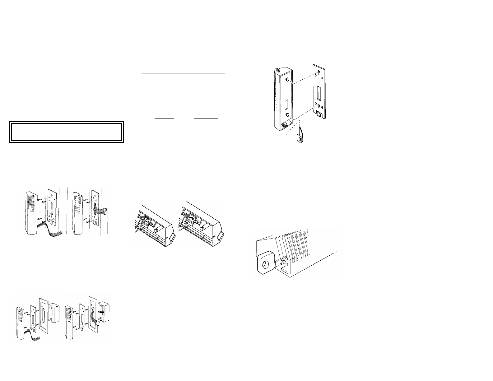
2. The adapter plate is generally used in wall mounting but
can be omitted if space is limited. See FIG 2.
Figure 2.
3. When required, use either the adapter plate or base plate
#6-32 self-tapping sheet metal screws provided, use a
Pigtail Connectorized
as a template to establish drill hole locations. If using the
3/32" diameter drill. If desired, suitable molly fasteners,
etc., (not provided) can be used. Use the center
rectangular hole in the plate as a guide to remove
sufficient material for wire and connector clearance. See
FIG 3.
Pigtail Connectorized
CAUTION
Figure 3.
4. Pull an appropriate length and gauge of 5 or 6-wire
conductor cable between host and reader (or connector).
#22 AWG up to 200 feet
#18 AWG up to 500 feet
5.
Connectorized - Models 6448 and 6449
Connect the wires of the 5-wire cable connector
assembly to the cable end at the reader location.
Connections can be crimped or made with twist-on
wire nuts. Do not plug the connector into the
reader yet.
Pigtail Cable - Models 6444, 6445, 6446 and 6447
Connect the wires of the 6-conductor cable
assembly to the cable end at the reader location.
Connections can be crimped or made with twist-on
6. Connect the other end of the cable to the host controller
wire nuts.
being sure to follow the appropriate color code and wire
lead functions.
FUNCTION WIRE COLOR
+5 VDC RED
COMMON BLACK
Data "1" Output WHITE
Data "0" Output GREEN
LED control line A BROWN
LED control line B (opt) YELLOW
HEATER BAR* BLUE*
* - Models 6446/6447: The two BLUE wires
connect to the HEATER BAR, which must be
powered by a 24 VAC or 24 ADC source.
Head Track Adjustment
The reader head track location may be changed in the field by
snapping out the head/gimbal assembly, rotating the assembly
180 degrees, and re-installing the assembly in the reader case.
Track I Track II
Head wires
toward
face of reader
.
Head wires
away from
face of reader
Attaching Reader to Base Plate
1. On Models 6448 and 6449 only, plug the cable connector
assembly into the back of the reader (the plug is designed
to fit only one way). On all other models, the cable should
already be connected.
2. Align the two protruding retainer pins in the underside of
the reader assembly with the corresponding holes in the
reader base plate. FIG 4.
Figure 4
3. Fully insert these pins into base plate holes and gently
slide the reader assembly in the direction of the base plate
latch (approximately 1/4" or 6.35 mm) until the latch locks
against the latch release stop.
Releasing Reader from Base Plate
1. To release the reader assembly from the reader base
plate, insert the latch release tool into the reader assembly
release slot, making sure the tip of the tool rides on top of
the latch. When fully inserted, the tip of the tool will
depress the latch sufficiently to clear the release stop.
FIG 5.
2. W hile holding the release tool in this position, slide the
reader assembly forward (approximately 1/4" or 6.35 mm)
and lift the reader off its base.
3. Disconnect (or unplug) the cable connector assembly from
the back of the reader.
Figure 5.
Options
Reader options are selected by a 16 position rotary switch
located at the top of the reader circuit board.
NOTE: For Model 644-S, Custom proms have a custom ABA
format and may not follow the table below.
The options control the card type accepted (ABA or EMPI) as
well as the output format.
Switch
Position
0 Northern card to 32 bit Wiegand
(FC=16 bits. ID=16 bits)
1 ABA card, all bits raw data - clock and data
2 Reserved for Custom Prom
3 ABA card all bits raw data, except leading 0’s
stripped - clock & data
4 ABA card all ABA digits, plus 10 leading & 10
trailing 0’s - clock & data output
5 ABA card all ABA digits, plus 10 leading & 10
trailing 0’s - Wiegand output
6 ABA card convert last 4 ABA digits in first field
to binary and output as 26 bit Wiegand
7 ABA card convert last 7 ABA digits in first field
to binary and output as 26 bit Wiegand
8 EMPI card to 26 bit Wiegand
9 EMPI card to 34 bit Wiegand
A ABA card, convert last 9 ABA digits in first
field to binary and output as 34 bit Wiegand
B Basic MS raw output - all bits Wiegand in
order received
C ABA to 26 bit Wiegand (FC=8 bits, ID=16 bits)
D ABA to 34 bit Wiegand(FC=16 bits ID=16 bits)
E ABA to 34 bit Wiegand (Mercury compatible)
(FC=12 bits, ID=20 bits)
F ABA to 26 bit Wiegand (Mercury compatible)
(FC=8 bits, ID=16 bits)
Function
Self Test
On power-up, the reader does a self test sequence. Observe
that the reader LED flashes green four times.
If the reader does not complete self test or continues with
short double flashes, verify wire connections and voltage.
If the reader completes the self-test by flashing the LED but will
not read cards the following steps apply:
1. Check that the voltage at the red and black
wires is between 3.2 and 5.5 volts DC.
2. Read card for the proper format as selected.
The LED should wink dark momentarily.
3. Try another card.
4. See Diagnostic Test section.
Diagnostic Test
1. The Model 644 Pass-Through Card Reader is factory
calibrated and not field serviceable.
2. Direct substitution with a known good reader is the best
way to isolate the problem.
3. Measure the voltage drop at the reader between the RED
(Positive) and the BLACK (Common) wire. It should
measure between 3.2 and 5.5 VDC. Low voltage is a
common source of problems.
4. Verify that the card used to test is a known good card, and
is authorized in host memory. Verify the reader options
are set correctly for that particular host, and the proper site
code has been recorded in host memory.
5. Verify the wiring, continuity, and connections between
reader and host. If possible, switch the reader input wiring
at the host to another known good input terminal and
retest.
6. If the problem still can not be resolved, contact your HID
Authorized dealer for assistance.
 Loading...