

Page 1
Hickory Industries, Inc.
Installation Manual
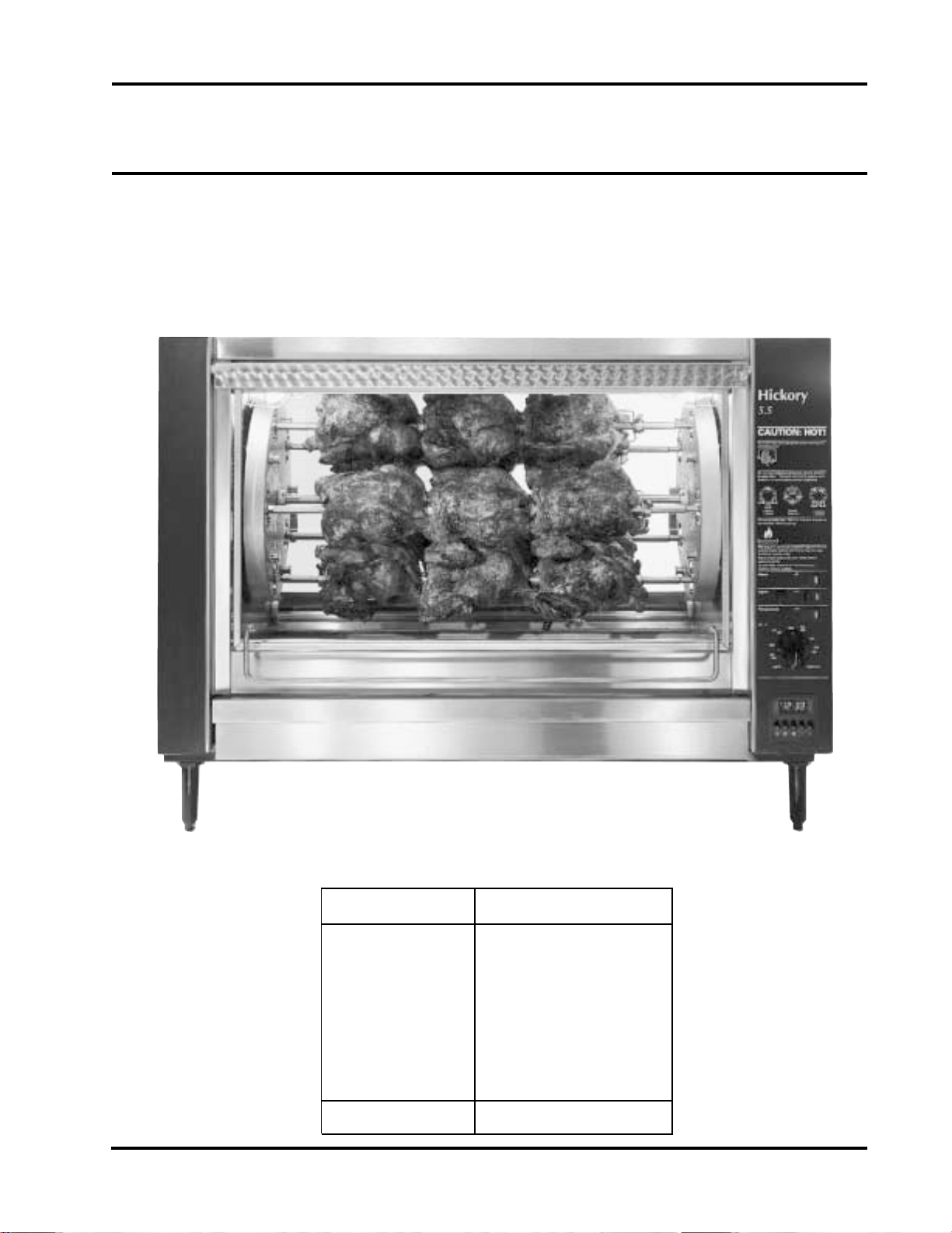
Hickory Rotisseries
Models: N/5.5 E
USA
Machine T ype N / 5. 5 E
T otal Power Rating
Elements / Spits
Electrical Rating
T emperature Range
Timer
Delivery Date:
4900 Westside Avenue, North Bergen, New Jersey 07047
Tel: [201] 223-0050 Fax: [201] 223-0950
6000 or 8400 Watts
4 Elements with 5 Spits
208/240 V or 380/410 V
200ºF - 550ºF
Manual or Fully Automatic
Final Inspection:
N/5.5E Installation 8/5/97
Page 1 of 15
Page 2

Hickory Industries, Inc.
Table of Contents
1.0 Installation Instructions 3
1. 1 General Information 4
1. 2 Description of the Data Plate 4
1.3 Machine Drawings and Dimensions 6
1. 4 Electrical Conversion and Adjustment Instructions 7
1. 5 Cooking Cycle 7
1.6 Maintenance, Response to T echnical Problems 7
1.6.1 Reasons for Problems and Solutions 8
1. 7 Spit Drive Mechanism 9
1. 8 N/5.5E Parts List 1 0
1. 9 N/5.5E Exploded View 1 2
4900 Westside Avenue, North Bergen, New Jersey 07047
Tel: [201] 223-0050 Fax: [201] 223-0950
N/5.5E Installation 8/5/97
Page 2 of 15
Page 3

Hickory Industries, Inc.
1.0 Installation Instructions
a. When installing these units, it is important to comply with the most recently
established rules and regulations as deemed pertinent by the local and national
electrical, ventilation, sanitation, and fire codes. These units are classified
by Underwriters Laboratories, Inc. as Electrically Heated Food Service Equipment.
b . Electric units must not be directly connected to a flue or exhaust vent. However ,
electric units may require operation in conjuction with a canopy type exhaust hood if
deemed necessary by local authorities.
c . The units must be installed in such a way that proper ventilation and heat exchange is
assured. The room must be ventilated in accordance to the valid codes and
regulations.
d . The units are to be installed securely and horizontally . The units may be installed on
combustible floors. The units must be installed with adjustable legs if placed on a
combustible surface.
e . The minimum clearance to the rear or side walls must be 13 inches. It is also
important to insure that the bottom of the units is kept clear so that proper ventilation
or air exchange can occur . Rear clerance can be reduced to 1" with the repalcement of
the rear glass with metal panels.
f. Normally , the units will be sent to the operator already set up for the particular
electrical service available at their location. However, unless otherwise specified, the
electric units are set up for 208 V , 3 Phase, 60 Hz use. Before installing and using the
units for the first time, it is important to make sure that the electrical power indicated
on the data plate matches the type of electrical power available in the location.
Should this not be the case, it is imperative to change or convert the units to the
needed types.
g. Electric units must be hard-wired or fitted with a power cord by a licensed
electrician.
4900 Westside Avenue, North Bergen, New Jersey 07047
Tel: [201] 223-0050 Fax: [201] 223-0950
N/5.5E Installation 8/5/97
Page 3 of 15
Page 4
1. 1 General Information
®
The Operating Instructions are to be given to the operator of the rotisserie. All unit
operators are to be familiar with the functions of the rotisserie.
The Operating Instructions should be kept in a location close to the rotisserie. It should be
easily recognizeable and easily accessible.
Electric units can be ordered to meet most electrical specifications.
It is recommended that a repair and maintenance contract be signed with the
manufacturer's agent, distributor, or service agency .
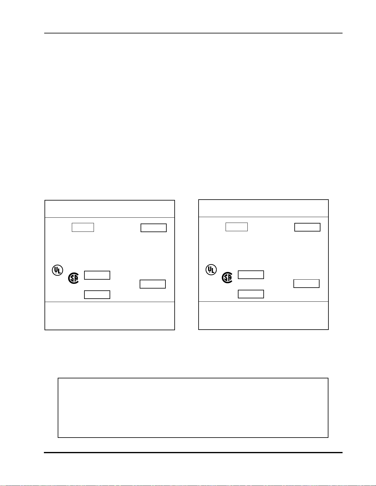
1. 2 Description of the Data Plate
Hickory Industries, Inc.
HICKORY INDUSTRIES, INC.
NORTH BERGEN, NJ 07047
MODEL: N/5.5 E M SERIAL NO.
MOTOR: 1 10 - 120 VOLTS 60 CYCLE AC
CURRENT
WATTS SINGLE PHASE 3 RPM
HEATING ELEMENTS 208 VOLTS 60 CYCLE
LISTED
607C
MFG. DATE
MINIMUM INSTALLATION
CLEARANCES
MAXIMUM W A TTAGE PER LAMP 40 WATTS
3 PHASE AC
CURRENT
1400 WA TTS PER ELEMENT
ELEMENTS
4
®
TOTAL WATTAGE
SIDES: 13 INCHES
BACK: 13 INCHES
6000
HICKORY INDUSTRIES, INC.
NORTH BERGEN, NJ 07047
MODEL: N/5.5 E M SERIAL NO.
MOTOR: 1 10 - 120 VOLTS 60 CYCLE AC
CURRENT
WATTS SINGLE PHASE 3 RPM
HEATING ELEMENTS 208 VOLTS 60 CYCLE
LISTED
607C
MFG. DATE
MINIMUM INSTALLATION
CLEARANCES
MAXIMUM W A TT AGE PER LAMP 40 WA TTS
1 PHASE AC
CURRENT
1400 WA TTS PER ELEMENT
ELEMENTS
4
TO TAL WAT TAG E
SIDES: 13 INCHES
BACK: 13 INCHES
6000
WARNING!
This unit must be installed and connected in accordance to the latest regulations
and may require operation in conjunction with a forced ventilation or exhaust hood.
This unit has been designed for professional use only
and may only be installed or repaired by licensed service agencies!
Before installing or using this equipment, read these instructions!
4900 Westside Avenue, North Bergen, New Jersey 07047
Tel: [201] 223-0050 Fax: [201] 223-0950
N/5.5E Installation 8/5/97
Page 4 of 15
Page 5
Hickory Industries, Inc.
®
®
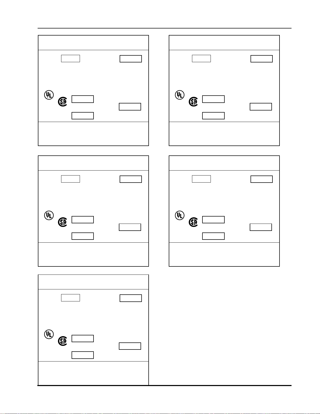
HICKORY INDUSTRIES, INC.
NORTH BERGEN, NJ 07047
MODEL: N/5.5 E M SERIAL NO.
MOTOR: 208 - 220 VOLTS 60 CYCLE AC CURRENT
WATTS SINGLE PHASE 3 RPM
HEATING ELEMENTS 208 VOLTS 60 CYCLE
LISTED
607C
MFG. DATE
MINIMUM INSTALLATION
CLEARANCES
MAXIMUM W A TTAGE PER LAMP 40 WATTS
3 PHASE AC
CURRENT
1400 WA TTS PER ELEMENT
ELEMENTS
4
®
TOTAL WATTAGE
SIDES: 13 INCHES
BACK: 13 INCHES
6000
HICKORY INDUSTRIES, INC.
NORTH BERGEN, NJ 07047
MODEL: N/5.5 E M SERIAL NO.
MOTOR: 208 - 240 VOLTS 50 CYCLE AC CURRENT
WATTS SINGLE PHASE 3 RPM
HEATING ELEMENTS 208 VOLTS 50 CYCLE
LISTED
607C
1 PHASE AC
CURRENT
1400 WA TTS PER ELEMENT
ELEMENTS
4
®
TOTAL WATTAGE
6000
HICKORY INDUSTRIES, INC.
NORTH BERGEN, NJ 07047
MODEL: N/5.5 E M SERIAL NO.
MOTOR: 1 10 - 120 VOLTS 60 CYCLE AC CURRENT
WATTS SINGLE PHASE 3 RPM
HEATING ELEMENTS 208 VOLTS 60 CYCLE
LISTED
607C
MFG. DATE
MINIMUM INSTALLATION
CLEARANCES
MAXIMUM W A TT AGE PER LAMP 40 WA TTS
3 PHASE AC
CURRENT
2000 WA TTS PER ELEMENT
ELEMENTS
4
TOTAL WATTAGE
SIDES: 13 INCHES
BACK: 13 INCHES
8000
HICKORY INDUSTRIES, INC.
NORTH BERGEN, NJ 07047
MODEL: N/5.5 E M SERIAL NO.
MOTOR: 208 - 240 VOLTS 50 CYCLE AC CURRENT
WATTS SINGLE PHASE 3 RPM
HEATING ELEMENTS 208 VOLTS 50 CYCLE
LISTED
607C
3 PHASE AC
CURRENT
1400 WA TTS PER ELEMENT
ELEMENTS
4
TOTAL WATTAGE
6000
MFG. DATE
MINIMUM INSTALLATION
CLEARANCES
MAXIMUM W A TTAGE PER LAMP 40 WATTS
SIDES: 13 INCHES
BACK: 13 INCHES
HICKORY INDUSTRIES, INC.
NORTH BERGEN, NJ 07047
MODEL: N/5.5 E M SERIAL NO.
MOTOR: 208 - 240 VOLTS 50 CYCLE AC CURRENT
WATTS SINGLE PHASE 3 RPM
HEATING ELEMENTS 208 VOLTS 50 CYCLE
LISTED
607C
MFG. DATE
MINIMUM INSTALLATION
CLEARANCES
MAXIMUM W A TTAGE PER LAMP 40 WATTS
3 PHASE AC
CURRENT
2000 WA TTS PER ELEMENT
ELEMENTS
4
®
TOTAL WATTAGE
SIDES: 13 INCHES
BACK: 13 INCHES
4900 Westside Avenue, North Bergen, New Jersey 07047
8000
Tel: [201] 223-0050 Fax: [201] 223-0950
MFG. DATE
MINIMUM INSTALLATION
CLEARANCES
SIDES: 13 INCHES
BACK: 13 INCHES
MAXIMUM W A TT AGE PER LAMP 40 WA TTS
N/5.5E Installation 8/5/97
Page 5 of 15
Page 6
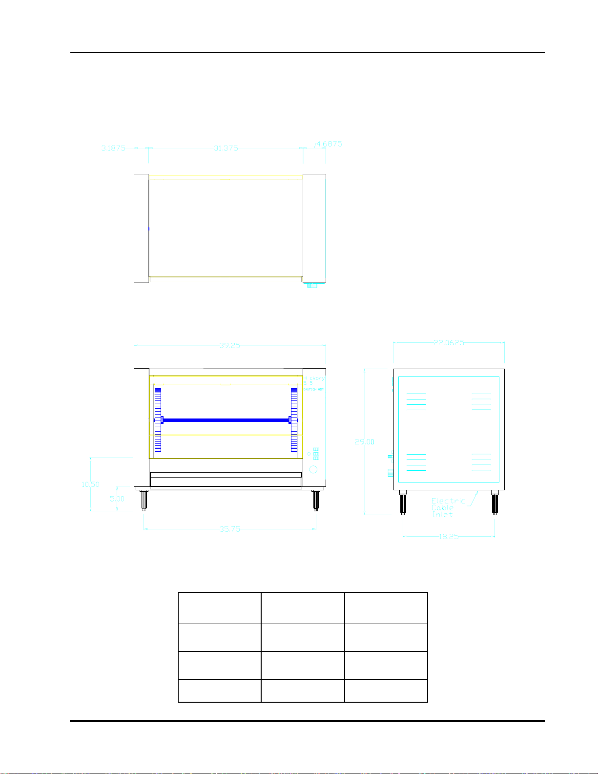
1.3 Machine Drawings and Dimensions
The following drawing of the Front View , Side View, and Top V iew indicate where the
dimensions are taken and should be used to plan the installation of the units.
N/ 5.5 E
Top View
Hickory Industries, Inc.
Front View Right Side View
N/ 5.5 E inches mm
Height 29" 737
Width 39-1/4" 997
Depth 22-1/16" 560
4900 Westside Avenue, North Bergen, New Jersey 07047
Tel: [201] 223-0050 Fax: [201] 223-0950
N/5.5E Installation 8/5/97
Page 6 of 15
Page 7

1.4 Electrical Conversion and Adjustment Instructions
Before converting or adjusting the machine to another type of electricity , it is imperative that
electrical power to the machines should also be turned off. When converting, make sure that
the proper electrical diagram is followed and that the motor and timer match the connected
single phase voltage!
1.5 Cooking Cycle
In order to start the cooking cycle, the elements must be powered. The heating cycle will
start only when the following procedure is followed:
a. The TEMPERA TURE switch is turned to "on".
b. A cooking temperature must be set on the thermostat (i.e. 450°F).
c. The cooking timer must be activated (see Operating Instructions).
Once these steps are completed, the unit will call for heat and the cooking cycle will be
activated. The main contactor, which powers the heating elements, will stay on until the
set cooking temperature is reached, as sensed by the thermocouple attached to the thermostat.
With the temperature reached, the electrical power to the elements will be cut off as the
thermostat shuts off the power to the contactor . When the temperature drops below the set
point, electrical power is again sent to the heating system, thus starting the heating process
all over . The system will cycle on and off as needed to maintain the set cooking point.
Hickory Industries, Inc.
1.6 Maintenance, response to technical problems.
Should a technical problem arise for any reason, shut off the machine and call for technical
service.
A routine maintenance should be carried out at least once a year . Contact your local,
certified service company for maintenance.
4900 Westside Avenue, North Bergen, New Jersey 07047
Tel: [201] 223-0050 Fax: [201] 223-0950
N/5.5E Installation 8/5/97
Page 7 of 15
Page 8

1.6.1 Reasons for Problems and Solutions
Hickory Industries, Inc.
Problem
Unit does not heat.
Unit takes too
long to cook.
Cause
a . Rotisserie not "on".
a . T emperature set too low.
b . Timer is not properly set.
Solution
1. Make sure that the TEMPERA TURE
switch is on.
2. Thermostat must be set (i.e. 550°F).
The cooking timer must be operational
(cook cycle).
3. A red LED on the TEMPERA TURE
switch indicates that the contactor is
supplying power to the heating
elements.
4. Using the electrical diagram, make
sure that the entire system is fully
functional.
a . T o cook chickens, we suggest that the
temperature be set to MAXIMUM. If
the chickens are "burning", which is
usually due to sugars in the marinade
or rub, then the temperature must be
reduced accordingly .
b . When programming the timer , it will
only heat up the rotisserie when a
"cook pot" appears on the display .
Before setting a cooking time, make
sure that enough time is programmed!
c. Chicken are too big.
d. Not enough power is being
supplied to the unit.
e . The lower metal deflectors
are on backwards.
c. A load of 20 chickens, each about
3.25 lbs., will take about 1 hour and
30 minutes to cook in a 6400 Watt
unit. The larger the chickens, the
longer the cooking time.
d. Make sure that the hot, neutral, and
ground leads are properly matched up.
Also make sure that all of the phases
are live.
e . The two lower heating elements have
two concave deflectors which direct
the heat towards the center of the
chamber . A common error is to
cover the elements, preventing the heat
from reaching the center of the unit.
4900 Westside Avenue, North Bergen, New Jersey 07047
Tel: [201] 223-0050 Fax: [201] 223-0950
N/5.5E Installation 8/5/97
Page 8 of 15
Page 9
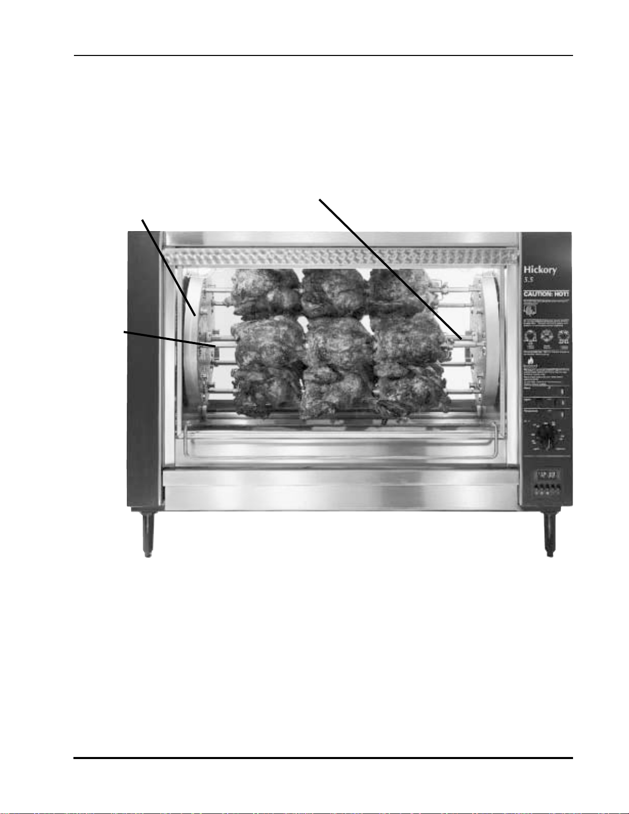
1.7 Spit Drive Mechanism
This unit is equipped with a planetary motion spit drive system. This means that each spit is
turning upon its axis at the same time that they turn about the center shaft. When the motor
switch is turned to on, the disks and the spits will begin to turn. Insure that the mechanism
turns smoothly when testing the unit.
Hickory Industries, Inc.
Aluminum Drive
Disk
Spit
Center Shaft
Before cooking, it is imperative that the center shaft be covered and protected with aluminum foil. This will
prevent fats from carbonizing on the shaft, making the removal of the aluminum disks much easier in the
future. If the shaft is not protected, it may eventually be impossible to remove the disks should there be a
problem in the spit drive mechanism.
The driven and the stationary drive gears are located behind the aluminum drive disk. These can be
viewed by taking out the removable aluminum disks. The driven gears and the stationary gear should
be viewed once a week to check for fat or carbonization build-up. Any fat or dirt should be cleaned
off since a build-up will eventually damage the drive system.
4900 Westside Avenue, North Bergen, New Jersey 07047
Tel: [201] 223-0050 Fax: [201] 223-0950
N/5.5E Installation 8/5/97
Page 9 of 15
Page 10

Hickory Industries, Inc.
1. 8 N/5.5E Parts List
Item Qty . Description Material Length Size Manufacturer
55 3 1 Shaft 5/8 (Removable Drums - Center) SS 5/8" Hickory
55 4 1 Shaft Locking Slide SS Hickory
51 9 1 Drive Bearing Holder (Left - with brass bearing) Steel (Chromed) Hickory
52 0 1 Drive Bearing Holder (Right - with teflon bearing) Steel (Chromed) Hickory
1 Brass Shaft Bearing Brass Hickory
56 6 1 T eflon Shaft Bearing T eflon Hickory
50 1 1 Aluminum Disk Drive (Bare) Cast Al umin um Hickory
50 2 1 Aluminum Disk Slave (Bare) Cast A luminum Hickory
50 3 1 Alum. Disk Drv. (Complete w/ Spit Driven Gears) Hickory
50 4 1 Alum. Disk Slave (Complete w/ Spit Supports) Hickory
51 4 1 Disk Retaining Pin Steel 1-1/2" 5/32" Hickory
56 4 5 T eflon Spacers - 1/4" round Hickory
50 5 Aluminum Disk T eflon Coating Hickory
56 1 5 Spit Driven Gear Assembly Steel (Chromed) Hickory
555 5 Snap Ring (Gears) Steel Hickory
55 9 5 Spit Driven Gear Bearing Holder Steel (Chromed) Hickory
56 0 5 Spit Driven Gear Steel (Chromed) Hickory
56 5 5 Teflon Spit Driven Gear Bearing 1/4" Hickory
563 1 Stationary Gear Steel Hickory
56 2 5 Spit Support Steel (Chromed) Hickory
51 0 1 Chain (Roller - 5.5) Steel Hickory
5 1 1 1 Chain Link (Roller - 5.5) Steel Hickory
52 1 1 Drive Sprocket - Roller Chain Steel Hickory
52 2 1 Driven Sprocket - Roller Chain Steel Hickory
1 Drive Shaft
51 2 1 Chain Tensioner Steel Hickory
509 1 Buss Fuse 0.5 Amp Buss
52 7 1 Fuse Holder 0.5 Amp
53 8 4 Lamp Cover Steel (Chromed) Hickory
5 4 1 3 Micro Switch & Toggle Marquardt
567 1 Thermostat 200-550
56 8 1 Thermostat Knob
56 9 1 Timer (without Adapter) Eaton
569a 1 Adapter (for Timer) Eaton
54 2 1 Motor Gear - 120V Bodine
53 9 1 Lamp, 120 V Hickory
540 4 Lamp Socket Ceramic Leviton
12 0 1 Drip Pan (5.5) SS Hickory
12 1 1 Drip Pan Plug Brass Hickory
122 1 Drip Pan Receptacle Brass Hickory
4900 Westside Avenue, North Bergen, New Jersey 07047
Tel: [201] 223-0050 Fax: [201] 223-0950
N/5.5E Installation 8/5/97
Page 10 of 15
Page 11

Hickory Industries, Inc.
1.8 N/5.5E Parts List (Contd.)
Item Qty . Description Material Length Size Manufacturer
12 3 1 Electrical Grounding Cap Hickory
Electrical Wire Janor Wire
106 1 Buchanan Contact Section 824 Buchanan
107 1 Buchanan Contact Section 830 Buchanan
55 0 1 Relay (Contactor) 3 Pole 220V G E
1 Capacitor GE
52 5 8 Element Holder Hickory
12 9 4 Element Porcelain Insulator Hickory
52 3 4 Element, Straight 220 V - 1400 Watt Glenn
52 4 4 Element, Straight 240 V - 1400 Watt Glenn
54 9 2 Reflector SS Hickory
513 2 Glass Hinge SS Hickory
51 5 2 Door Bearing Brass Brass Hickory
51 6 1 Door Handle (Metal) Steel Hickory
51 8 1 Door Spring (Mechanical) Steel Hickory
545 1 Pneumatic Spring
53 2 1 Glass Tempered Large (Door) Glass 28.94" x 16.5" Hickory
533 1 Glass T empered (Rear) Glass 28.94" x 12" Hickory
53 4 1 Glass Tempered (Rear - Small) Glass 28.94" x 4.5" Hickory
52 6 4 Feet Adjustable Plastic Plastic Hickory
55 6 5 Spit Complete (incl. all skewers & screws) SS Hickory
18 5 5/Spit Skewer Double SS Hickory
18 6 5/Spit Skewer Single SS Hickory
21 9 1/Skw.Thumb Screw Steel Hickory
55 7 1 Spit Turkey Center only SS Hickory
22 5 2 Turkey Skewers Single SS Hickory
506 5 Basket Hanging Steel (Chromed) Hickory
507 5 Basket Bearing Brass Brass Hickory
439a Angle (V) Spits (Option!) SS Hickory
50 8 Basket Spits ( Steel (Chromed) Hickory
4900 Westside Avenue, North Bergen, New Jersey 07047
Tel: [201] 223-0050 Fax: [201] 223-0950
N/5.5E Installation 8/5/97
Page 11 of 15
Page 12

1.8 N/5.5E Exploded View
Hickory Industries, Inc.
4900 Westside Avenue, North Bergen, New Jersey 07047
Tel: [201] 223-0050 Fax: [201] 223-0950
N/5.5E Installation 8/5/97
Page 12 of 15
Page 13
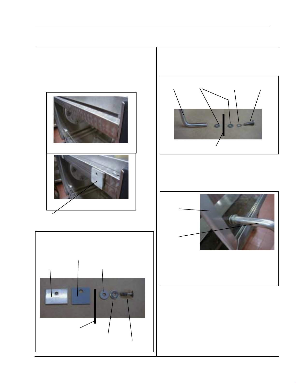
Hickory Industries, Inc.
Glass Replacement on the
5.5E & 10.10E Machines
Make sure that the handle and all associated hardware
is available at the site or order the mounting kit from
Hickory .
Make sure that the glass bar is in the open
position.
Closed Position
Make sure that the handle and all associated hardware
is available at the site or order the mounting hardware
from Hickory .
Glass handle, flat washer, lock washer , 10/32 screw
Glass
The glass mounts between the glass handle and the flat
washer.
Install the glass handle. Be sure to use Loc-Tite.
Open Position
Newer style units incorporate the spacer welded
on the glass bar..
Upper mounting hardware
Square silicon washer
Metal spacer
Glass
Round silicone washer
Flat washer
1/4-20 x 1” special screw
Glass
Frame
Glass
Handle
NOTE: THE 90 BEND ON THE GLASS
HANDLE IS LOWER THAN THE GLASS. DO
NOT MOUNT THE HANDLE WITH THE 90
DEGREE BEND UP .
USE HIGH TEMPERA TURE LOC-TITE
on all screws for both the glass handle and the
upper mounting screws.
Otherwise the handle will come loose and chip
the glass or fall slightly and chip around the
mounting screw holes. This will lead to breakage!
4900 Westside Avenue, North Bergen, New Jersey 07047
Tel: [201] 223-0050 Fax: [201] 223-0950
Column 2Column 1
N/5.5E Installation 8/5/97
Page 13 of 15
Page 14
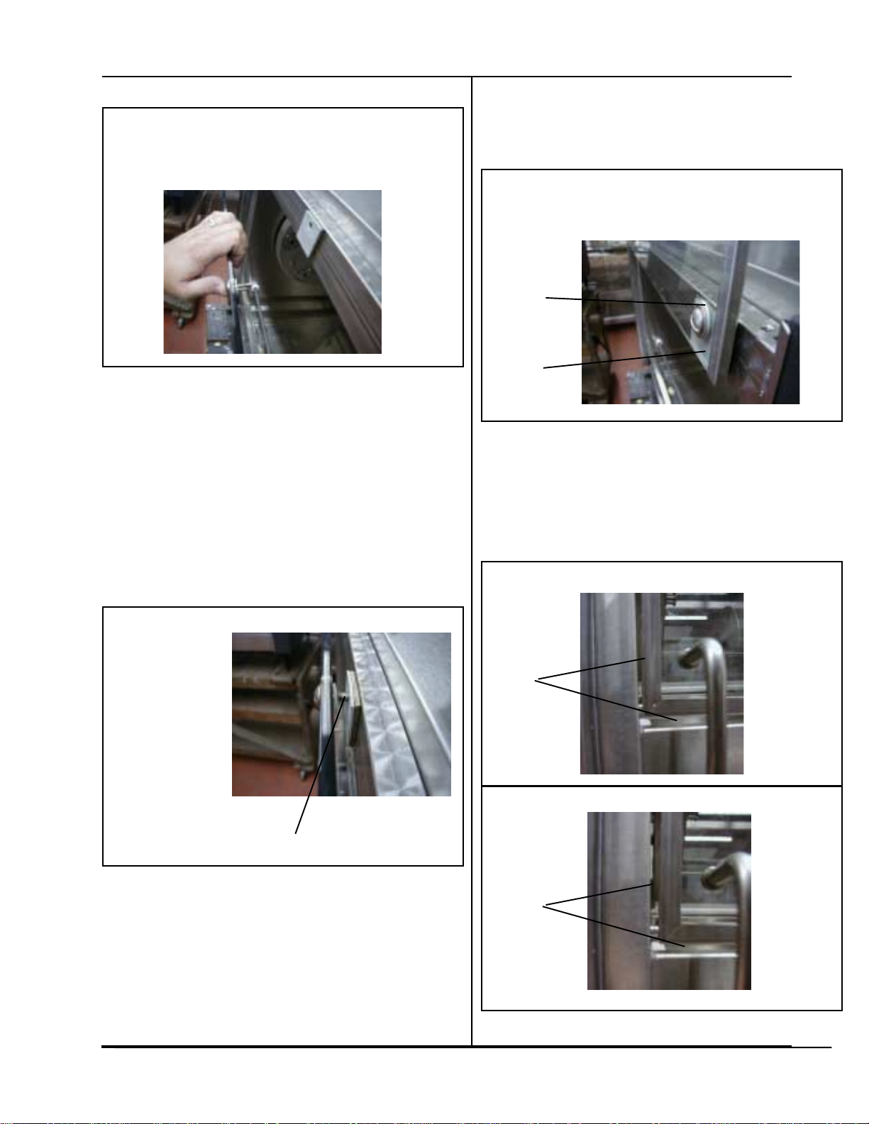
Replacing the front glass
Insert the screw on to the glass (use hi heat Loc-tite).
As a hint, start with the middle screw it will give you
some leverage with the glass.
Slowly turn the screw onto the glass bar - DO NOT
TIGHTEN. Make sure that you do not see any
threads or that the glass rests on the threads.
Make sure that when resting the glass on the
screws, it only rests on the un-threaded portion
of the screw (closest to the head of the screw).
Before moving glass make sure threads are inserted
onto metal spacer
Hickory Industries, Inc.
DO NOT TIGHTEN. This will ensure that you have
enough play to move the glass around without
bumping the glass.
Proceed with the remaining screws (use hi heat Loctite). Make sure that the glass is sandwiched between silicone washer and the silicone spacer .
Silicone
Washer
Silicone
Spacer
Slightly turn each screw until snug. It should be snug
but loose enough to move . Adjust the glass so that
the spacing is even around the sides and bottom of
the machine. Y ou can now verify the glass spacing
with the side and the bottom of the machine.
Improperly Spaced
Threads Exposed
4900 Westside Avenue, North Bergen, New Jersey 07047
Tel: [201] 223-0050 Fax: [201] 223-0950
Note:
Uneven
Spacing
Note:
Even
Spacing
Properly Spaced
N/5.5E Installation 8/5/97
Column 4Column 3
Page 14 of 15
Page 15

If the glass is not evenly spaced, adjust the glass until
its evenly spaced.
CAUTION: If the screws are not snug enough, when
lowering the glass door, the glass my hit the screws
and chip the glass.
CAUTION: When tightening the screws, if the glass
shifts down, the glass door will be too close to the
roof of the machine when the glass door is shut.
Open door and tighten upper mounting screws.
Close the door and verify that the side and bottom
spacing is even all around.
Make sure all screws are tight and have been replaced
using hi heat Loc-Tite.
Hickory Industries, Inc.
Return equipment back to operating condition.
Caution
Operators should not use a razor blade
or knife to clean the glass.
Glass should not be cleaned with abrasives, soft scrub or any pad, i.e. Brillo,
Scotch Brite, scouring pad etc. This
will scratch the glass and render the
glass faulty.
Tempered glass will break if scratched,
shipped or mishandled in any way. It
can break in a day or a year. BUT IT
WILL BREAK.
4900 Westside Avenue, North Bergen, New Jersey 07047
Column 5
Tel: [201] 223-0050 Fax: [201] 223-0950
Left Blank Intentionally
N/5.5E Installation 8/5/97
Page 15 of 15
 Loading...